EP3761484A1 - Permanent magnet motor - Google Patents
Permanent magnet motor Download PDFInfo
- Publication number
- EP3761484A1 EP3761484A1 EP18908031.0A EP18908031A EP3761484A1 EP 3761484 A1 EP3761484 A1 EP 3761484A1 EP 18908031 A EP18908031 A EP 18908031A EP 3761484 A1 EP3761484 A1 EP 3761484A1
- Authority
- EP
- European Patent Office
- Prior art keywords
- slit
- slits
- permanent magnet
- disposed
- rotor
- Prior art date
- Legal status (The legal status is an assumption and is not a legal conclusion. Google has not performed a legal analysis and makes no representation as to the accuracy of the status listed.)
- Pending
Links
Images


Classifications
-
- H—ELECTRICITY
- H02—GENERATION; CONVERSION OR DISTRIBUTION OF ELECTRIC POWER
- H02K—DYNAMO-ELECTRIC MACHINES
- H02K29/00—Motors or generators having non-mechanical commutating devices, e.g. discharge tubes or semiconductor devices
- H02K29/03—Motors or generators having non-mechanical commutating devices, e.g. discharge tubes or semiconductor devices with a magnetic circuit specially adapted for avoiding torque ripples or self-starting problems
-
- H—ELECTRICITY
- H02—GENERATION; CONVERSION OR DISTRIBUTION OF ELECTRIC POWER
- H02K—DYNAMO-ELECTRIC MACHINES
- H02K1/00—Details of the magnetic circuit
- H02K1/06—Details of the magnetic circuit characterised by the shape, form or construction
- H02K1/22—Rotating parts of the magnetic circuit
- H02K1/27—Rotor cores with permanent magnets
- H02K1/2706—Inner rotors
- H02K1/272—Inner rotors the magnetisation axis of the magnets being perpendicular to the rotor axis
- H02K1/274—Inner rotors the magnetisation axis of the magnets being perpendicular to the rotor axis the rotor consisting of two or more circumferentially positioned magnets
- H02K1/2753—Inner rotors the magnetisation axis of the magnets being perpendicular to the rotor axis the rotor consisting of two or more circumferentially positioned magnets the rotor consisting of magnets or groups of magnets arranged with alternating polarity
- H02K1/276—Magnets embedded in the magnetic core, e.g. interior permanent magnets [IPM]
-
- H—ELECTRICITY
- H02—GENERATION; CONVERSION OR DISTRIBUTION OF ELECTRIC POWER
- H02K—DYNAMO-ELECTRIC MACHINES
- H02K21/00—Synchronous motors having permanent magnets; Synchronous generators having permanent magnets
- H02K21/12—Synchronous motors having permanent magnets; Synchronous generators having permanent magnets with stationary armatures and rotating magnets
- H02K21/14—Synchronous motors having permanent magnets; Synchronous generators having permanent magnets with stationary armatures and rotating magnets with magnets rotating within the armatures
Definitions
- the present application relates to a permanent magnet motor.
- slits inclined in one direction of rotation are provided in a rotor core surface of an IPM motor in order to reduce torque ripple (for example, refer to Patent Literature 2).
- an IPM has greater demagnetization resistance than a surface permanent magnet (SPM), and reluctance torque can be utilized, because of which a small motor with a high output can be realized by increasing an amount of current, thereby increasing torque density.
- SPM surface permanent magnet
- an IPM is such that a face opposing a stator inner diameter forms a rotor core with high magnetic permeability, because of which a magnetic flux that crosses a magnetic pole surface in a circumferential direction increases, and an air gap magnetic flux density is more liable to become locally excessive compared with an SPM.
- An existing permanent magnet motor is such that due to a local increase in magnetic flux density in an air gap, an electromagnetic excitation force proportional to two times the magnetic flux density acts, attempting to cause a stator to transform, because of which there is a problem in that motor vibration noise worsens.
- an electromagnetic excitation force proportional to two times the magnetic flux density acts, attempting to cause a stator to transform, because of which there is a problem in that motor vibration noise worsens.
- the application discloses technology for resolving the heretofore described kind of problem, and has an object of providing a permanent magnet motor such that a worsening of motor vibration noise can be restricted while securing a reduction in size and an increase in output, which are advantages of an IPM.
- a permanent magnet motor disclosed in the present application includes a stator, and a rotor disposed opposing an inner side of the stator and having a field pole of a rotor core in which a permanent magnet is embedded, wherein the field pole has a radius smaller than an arc centered on a shaft of the rotor, a multiple of slits are formed in the field pole, the multiple of slits are disposed so that an interval between a first central line positioned between a multiple of the slits and a second central line positioned between a neighboring multiple of the slits increases as the first central line and the second central line head toward an outer peripheral side of the rotor core, and of the multiple of slits of the field pole, a first slit disposed in a central position of the field pole, and a second slit and a third slit disposed on either side of the first slit, are disposed within 20% of a circumferential direction width of the permanent magnet.
- a permanent magnet motor such that a worsening of vibration noise of a motor can be restricted, while securing a reduction in size and an increase in output, which are advantages of an IPM, is obtained.
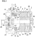
- Fig. 1 is an axial direction sectional view of a permanent magnet motor according to the first embodiment.
- the permanent magnet motor according to the first embodiment is used in, for example, an electric power steering system.
- a permanent magnet motor (hereafter referred to simply as "motor") 1 includes a rotor 22 having a rotor core 23 in whose interior a multiple of permanent magnets 25 are disposed, and supported so as to rotate freely, and a stator 12 provided across an air gap 50 on an outer side of the rotor 22. Also, the stator 12 includes a stator core 3 and a stator winding 5.
- the stator core 3 is formed by, for example, plate-form electromagnetic steel sheets being stacked, and the three-phase stator winding 5 is wound around the stator core 3 across an insulator 4 made of resin.
- the stator windings 5 of each phase are delta-connected by a winding terminal 7 housed in a terminal holder 6 made of resin.
- a connection terminal 8 for connecting to a lead wire 2 is attached to the winding terminal 7 of each phase.
- the connection terminal 8 is attached to a connection terminal base portion 9, and a nut 10 for attaching the lead wire 2 to the connection terminal 8 is housed in an interior of the connection terminal base portion 9.
- the stator core 3 is press-fitted into a frame 11 made of iron, forming the stator 12 of the motor 1.
- a frame 11 made of iron, forming the stator 12 of the motor 1.
- Another end portion of the frame 11 is opened, and a spigot joint portion 14 for linking to a housing 17 of the motor 1 is formed.
- a flange portion 15 having a screw clamping portion for screwing the stator 12 to the housing 17 of the motor 1 is formed on an outer periphery of the spigot joint portion 14 of the frame 11.
- An O-ring-form frame grommet 16 for waterproofing is provided between the housing 17 of the motor 1 and the flange portion 15 of the stator 12.
- the housing 17 of the motor 1 is formed by a die casting of an aluminum alloy, and a front bearing box 18 that houses a front bearing 27 for supporting one end of the rotor 22 is formed in a central portion. Also, a resolver mounting portion 20 for attaching a resolver 19, which is a rotation sensor for detecting an angle of rotation of the rotor 22, is formed in a vicinity of the front bearing box 18 of the housing 17.
- a mounting spigot joint portion 21 for attaching the motor 1 to a mating instrument is provided in an end portion of the housing 17 on a side opposite to a side on which the stator 12 is attached.
- the rotor 22 includes the rotor core 23, which is formed by electromagnetic steel sheets attached to an iron shaft 24 being stacked. Further, either end of the shaft 24 is supported by the rear bearing 26 and the front bearing 27 so as to rotate freely. A boss 28, which is coupling for linking to a mating instrument, is attached to a front side end portion of the shaft 24.
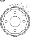
- Fig. 2A and Fig. 2B are front views of a rotor of a permanent magnet motor according to the first embodiment. Also, Fig. 2B is an enlarged view of Fig. 2A . As shown in Fig. 2A and Fig. 2B , the multiple of permanent magnets 25 are embedded in a circumferential direction in the rotor core 23 of the rotor 22. The multiple of permanent magnets 25 are housed and fixed in a multiple of permanent magnet mounting holes 47 disposed at equal intervals in the circumferential direction in the rotor core 23, and a gap portion 45 is formed on either side of the permanent magnet 25. Fig. 2A and Fig. 2B are centered on the rotor 22.
- the stator 12 has the stator core 3, which has a multiple of teeth 48 and a multiple of slots (not shown), and an armature winding (not shown) wound around the teeth 48 and housed in the slots.
- the rotor core 23 in the first embodiment has a floral form, and a multiple of slits 41 are formed in a field pole 40 of the rotor core 23 in which the permanent magnet 25 is embedded.
- the field pole 40 has a radius smaller than an arc centered on the shaft 24, which is attached on an inner side of the rotor 22.
- a central slit B in a center of the field pole 40 is such that a longitudinal axial direction (longitudinal direction) thereof is disposed in a radial direction of the rotor core 23 or a radial direction of an outer periphery of the floral form field pole 40.
- an odd number of slits 41 are disposed axisymmetrically sandwiching the central slit B disposed in the center of the field pole 40, and lengths of the slits 41 are axisymmetrically the same.
- a circumferential direction width of the permanent magnet 25 is greater than a radial direction width, and the permanent magnet 25 is of a flat plate magnet form.
- connection portion 44 is provided in order to integrate the field pole 40 divided by the slits 41.
- the field pole 40 divided by the slits 41 is integrated by the connection portion 44.
- the connection portion 44 is configured of a connection portion (field pole upper side) 44a or a connection portion (field pole lower side) 44b.
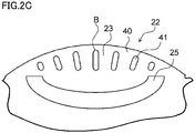
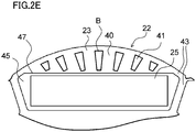
- Fig. 2C to Fig. 2E are front views of a rotor of a permanent magnet motor that is another example according to the first embodiment.
- a form of the permanent magnet 25 is a curved form, but structures excepting the permanent magnet 25 and a form of a permanent magnet mounting hole are the same as the structures in Fig. 2A .
- a form of the rotor core 23 opposing a bridge portion 43 is a perfectly circular form 46, but structures excepting this form are the same as the structures in Fig. 2A .
- a form of the slit 41 is trapezoidal, but structures excepting the form of the slit 41 are the same as the structures in Fig. 2A .
- Fig. 3 to Fig. 5 are front views of a permanent magnet motor in a comparative example.
- Fig. 3 to Fig. 5 show the teeth 48 of the stator 12 provided across the air gap 50 on the outer side of the rotor 22.
- the external form of the rotor 22 is the perfectly circular form 46, because of which torque ripple increases.
- no slit 41 is provided in the rotor core 23, because of which a magnetic flux 49 crossing the field pole 40 of the rotor core 23 flows, and magnetic flux density in a region A of the air gap 50 increases.
- the intervals between the slits 41 become smaller the nearer to the outer peripheral side of the rotor core 23, and there is no longer an advantage of the magnetic flux density of the air gap 50 being dispersed because of the slits 41.
- poles and slots such as 10 poles and 12 slots, 14 poles and 12 slots, or 14 poles and 18 slots, wherein a mode such that a low order electromagnetic excitation force mode is small and vibration noise is liable to increase, for example, a secondary mode all round, occurs.
- One of the slits 41 is in the center of the field pole 40.
- the center of the field pole 40 is the place in which a sectional area of the field pole 40 with respect to the crossing magnetic flux 49 is greatest and the magnetic flux 49 flows most easily, and an advantage in that the magnetic flux 49 is interrupted by the slit 41 is obtained.
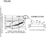
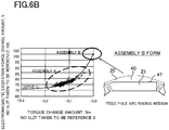
- Fig. 6A to Fig. 6C are drawings wherein amounts of change in electromagnetic excitation force and torque in a structure when slits are provided in a field pole and amounts of change in electromagnetic excitation force and torque in a structure (an assembly B) wherein slits are not provided in a field pole are plotted.
- a graph on which the amounts of change in electromagnetic excitation force and torque are plotted is shown on the left side, and a front view of a form of the assembly B, wherein slits are not provided in the field pole, is shown on the right side.
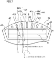
- Fig. 7 is a front view of a rotor of a permanent magnet motor according to the first embodiment.
- an assembly A with specifications designed using an optimum design tool of electromagnetic field analysis wherein five or seven slits 41 are disposed in the 10 pole, 12 slot motor 1 shown in Fig. 7 , and a position (a distance L between slits) and an angle ⁇ of the slits 41 are caused to change, so that a secondary component (a component causing transformation to an ellipse), which is a main component of electromagnetic excitation force that causes vibration noise in the stator core 3 or the frame 11, is minimal, and the assembly B with specifications such that the slit 41 is not disposed in the field pole 40, which is the reference for slit design, are plotted in Fig. 6A to Fig. 6C .
- a vertical axis shows an electromagnetic excitation force change rate
- a horizontal axis shows an amount of torque change.
- the vertical axis shows as a percentage (%) to what level the electromagnetic excitation force can decrease with respect to 100 owing to slit design.
- the horizontal axis shows to what extent the torque amount changes owing to slit design.
- the assembly B with the specifications that are the reference for slit design, is such that some forms of the rotor 22 from an almost perfectly circular form to a practically floral form are selected by changing the arc radius of the field pole 40, and taken to be proof showing that a tendency to be described below has universality, regardless of the design of the assembly B.
- the form of the assembly B shown on the right side of Fig. 6A corresponds to, for example, the floral form rotor 22 wherein the arc radius of the field pole 40 is small.
- the form of the assembly B shown on the right side of Fig. 6C corresponds to, for example, the rotor 22 with the almost perfectly circular form wherein the arc radius of the field pole 40 is large.
- the form of the assembly B shown on the right side of Fig. 6B corresponds to the rotor 22 having an arc radius of the field pole 40 midway between the form of the assembly B shown on the right side of Fig. 6A and the form of the assembly B shown on the right side of Fig. 6C .
- Fig. 6A to Fig. 6C are drawings wherein torque-electromagnetic excitation force curves C joining the assemblies B shown in Fig. 6A to Fig. 6C and assemblies A designed with slits based on each assembly B are plotted as exponential functions using the least squares method.
- Each curve C is a curve that gradually approaches 71%, and shows that electromagnetic excitation force can be considerably reduced by slit design to a maximum of a 71% level.
- an electromagnetic excitation force corresponding to a general time constant that is an index indicating a convergence speed from the assembly B that is the reference to 71% is taken to be 81% or less, it can be said that the electromagnetic excitation force can converge to a sufficiently small value in the assembly A owing to slit design.
- Fig. 8 is a drawing wherein analysis values obtained using the specifications of each of Fig. 6A to Fig. 6C are plotted, with a vertical axis as electromagnetic excitation force and a horizontal axis as a torque ripple value.
- triangular, diamond, and square plotting forms shown in assembly B are the form of one of the assemblies B, in which no slit is provided in the field pole 40, shown on the right side in Fig. 6A to Fig. 6C , but no particular correspondence relation between the plotting form and the form of the assembly B is specified here. The same applies to the assembly A.
- the assembly A is an assembly such that torque ripple decreases and also, conversely, worsens with respect to the assembly B, in which no slit 41 is provided in the field pole 40, as shown in Fig. 8 .
- Torque ripple worsening in comparison with the assembly B, which is the reference, due to slit design is because no balance is achieved between electromagnetic excitation force and torque ripple, and vibration noise caused by frame vibration and shaft vibration cannot be restricted, and it goes without saying that specifications such that torque ripple is equal to or less than that of the assembly B are specifications such that a clear advantage of achieving a balance between electromagnetic excitation force and torque ripple is obtained.
- the plotted data are divided into an assembly A1, wherein the electromagnetic excitation force value is somewhat high, and an assembly A2.
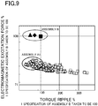
- Fig. 9 is a drawing wherein data corresponding to a second slit 41b and a third slit 41c neighboring a first slit 41a in the rotor 22 shown in Fig. 7 being disposed in positions greater than 20% with respect to a circumferential direction width W of the permanent magnet 25 are separated from the data plotted in Fig. 8 and replotted.
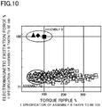
- Fig. 10 is a drawing wherein data corresponding to the second slit 41b and the third slit 41c neighboring the first slit 41a in the rotor 22 shown in Fig. 7 being disposed in positions within 20% with respect to the circumferential direction width W of the permanent magnet 25 are separated from the data plotted in Fig. 8 and replotted.
- the previously undifferentiated assembly A1 and assembly A2 can be differentiated between by focusing on achieving a balance between electromagnetic excitation force and torque ripple, and specifications such that electromagnetic excitation force can be further reduced can be selected.
- the first embodiment is such that, taking 20% with respect to the circumferential direction width W of the permanent magnet 25 as a threshold, torque ripple is reduced, and a form of the rotor 22 that reduces electromagnetic excitation force can be adopted, by the first slit 41a disposed in a central position of the field pole 40, and the second slit 41b and the third slit 41c disposed on either side of the first slit 41a, being disposed within 20% of the circumferential direction width of the permanent magnet 25.
- the motor 1 according to the first embodiment is such that a worsening of vibration noise can be reduced.
- the multiple of slits 41 are disposed so that electromagnetic excitation force, which forms a main component when a spatial order is a minimum order of two or more, decreases to 81% or less with respect to a case where a rotor core with no slit is adopted as a reference. Further still, the multiple of slits 41 are disposed in a state such that torque ripple is equal to or less than the torque ripple of a rotor core with no slit with respect to a case where the rotor core with no slit is adopted as a reference.
- Embodiments can be combined, and each embodiment can be modified or eliminated as appropriate.
Abstract
Description
- The present application relates to a permanent magnet motor.
- To date, with regard to a rotor of a permanent magnet motor, slits aligned so that neighboring intervals are practically equal have been provided in a rotor core surface of an IPM (interior permanent magnet) motor in order to improve demagnetization resistance of a permanent magnet (for example, refer to Patent Literature 1).
- Also, with regard to a magnet-embedded rotor of an existing motor, slits inclined in one direction of rotation are provided in a rotor core surface of an IPM motor in order to reduce torque ripple (for example, refer to Patent Literature 2).
- The previously described kinds of existing IPM motors have a main object of achieving an improvement in demagnetization resistance or a reduction of torque ripple. In the case of demagnetization resistance improvement, there is no need to adopt a complicated structure wherein slits are provided in a rotor surface as disclosed in
Patent Literature 1, as it is sufficient to apply a permanent magnet with a high coercive force. Also, in the case of torque ripple reduction, a structure having the kind of perfectly circular external rotor form disclosed inPatent Literature 2 is a form such that torque ripple worsens, so is not appropriate. - Generally, an IPM has greater demagnetization resistance than a surface permanent magnet (SPM), and reluctance torque can be utilized, because of which a small motor with a high output can be realized by increasing an amount of current, thereby increasing torque density.
-
- Patent Literature 1:
JP-A-2006-081336 - Patent Literature 2:
JP-A-2006-014450 - In this case, differing from an SPM, an IPM is such that a face opposing a stator inner diameter forms a rotor core with high magnetic permeability, because of which a magnetic flux that crosses a magnetic pole surface in a circumferential direction increases, and an air gap magnetic flux density is more liable to become locally excessive compared with an SPM.
- An existing permanent magnet motor is such that due to a local increase in magnetic flux density in an air gap, an electromagnetic excitation force proportional to two times the magnetic flux density acts, attempting to cause a stator to transform, because of which there is a problem in that motor vibration noise worsens. As reducing the motor current or enlarging the air gap causes the torque density to decrease, the advantages of reducing size and increasing output with respect to an SPM are cancelled out.
- The application discloses technology for resolving the heretofore described kind of problem, and has an object of providing a permanent magnet motor such that a worsening of motor vibration noise can be restricted while securing a reduction in size and an increase in output, which are advantages of an IPM.
- A permanent magnet motor disclosed in the present application includes a stator, and a rotor disposed opposing an inner side of the stator and having a field pole of a rotor core in which a permanent magnet is embedded, wherein the field pole has a radius smaller than an arc centered on a shaft of the rotor, a multiple of slits are formed in the field pole, the multiple of slits are disposed so that an interval between a first central line positioned between a multiple of the slits and a second central line positioned between a neighboring multiple of the slits increases as the first central line and the second central line head toward an outer peripheral side of the rotor core, and of the multiple of slits of the field pole, a first slit disposed in a central position of the field pole, and a second slit and a third slit disposed on either side of the first slit, are disposed within 20% of a circumferential direction width of the permanent magnet.
- According to the permanent magnet motor disclosed in the present application, a permanent magnet motor such that a worsening of vibration noise of a motor can be restricted, while securing a reduction in size and an increase in output, which are advantages of an IPM, is obtained.
-
- [
Fig. 1] Fig. 1 is an axial direction sectional view of a permanent magnet motor according to a first embodiment. - [
Fig. 2A] Fig. 2A is a front view of a rotor of the permanent magnet motor according to the first embodiment. - [
Fig. 2B] Fig. 2B is a front view of the rotor of the permanent magnet motor according to the first embodiment. - [
Fig. 2C] Fig. 2C is a front view of the rotor of the permanent magnet motor according to the first embodiment. - [
Fig. 2D] Fig. 2D is a front view of the rotor of the permanent magnet motor according to the first embodiment. - [
Fig. 2E] Fig. 2E is a front view of the rotor of the permanent magnet motor according to the first embodiment. - [
Fig. 3] Fig. 3 is a front view of a permanent magnet motor in a comparative example. - [
Fig. 4] Fig. 4 is a front view of a permanent magnet motor in a comparative example. - [
Fig. 5] Fig. 5 is a front view of a permanent magnet motor in a comparative example. - [
Fig. 6A] Fig. 6A is a drawing showing changes in electromagnetic excitation force and torque when slits are provided in a field pole. - [
Fig. 6B] Fig. 6B is a drawing showing changes in electromagnetic excitation force and torque when slits are provided in the field pole. - [
Fig. 6C] Fig. 6C is a drawing showing changes in electromagnetic excitation force and torque when slits are provided in a field pole. - [
Fig. 7] Fig. 7 is a front view of a rotor of the permanent magnet motor according to the first embodiment. - [
Fig. 8] Fig. 8 is a drawing wherein analysis values obtained usingFig. 6A to Fig. 6C are plotted, with a vertical axis as electromagnetic excitation force and a horizontal axis as a torque ripple value. - [
Fig. 9] Fig. 9 is a drawing wherein data corresponding to a second slit and a third slit neighboring a first slit being disposed in positions greater than 20% with respect to a circumferential direction width of a permanent magnet are separated from the data plotted inFig. 8 and replotted. - [
Fig. 10] Fig. 10 is a drawing wherein data corresponding to the second slit and the third slit neighboring the first slit being disposed in positions within 20% with respect to the circumferential direction width of the permanent magnet are separated from the data plotted inFig. 8 and replotted. Description of Embodiments - Hereafter, a first embodiment will be described, based on the drawings.
- Identical reference signs in the drawings indicate identical or corresponding components.
-
Fig. 1 is an axial direction sectional view of a permanent magnet motor according to the first embodiment. The permanent magnet motor according to the first embodiment is used in, for example, an electric power steering system. - As shown in
Fig. 1 , a permanent magnet motor (hereafter referred to simply as "motor") 1 includes arotor 22 having arotor core 23 in whose interior a multiple ofpermanent magnets 25 are disposed, and supported so as to rotate freely, and astator 12 provided across anair gap 50 on an outer side of therotor 22. Also, thestator 12 includes astator core 3 and a stator winding 5. - The
stator core 3 is formed by, for example, plate-form electromagnetic steel sheets being stacked, and the three-phase stator winding 5 is wound around thestator core 3 across aninsulator 4 made of resin. Thestator windings 5 of each phase are delta-connected by a windingterminal 7 housed in aterminal holder 6 made of resin. Furthermore, aconnection terminal 8 for connecting to alead wire 2 is attached to the windingterminal 7 of each phase. Theconnection terminal 8 is attached to a connectionterminal base portion 9, and anut 10 for attaching thelead wire 2 to theconnection terminal 8 is housed in an interior of the connectionterminal base portion 9. - The
stator core 3 is press-fitted into aframe 11 made of iron, forming thestator 12 of themotor 1. There is a bottom portion in one end portion of theframe 11, and a rearbearing box portion 13 that houses arear bearing 26 for supporting one end of therotor 22 is formed in a central portion of the bottom portion. Another end portion of theframe 11 is opened, and a spigotjoint portion 14 for linking to ahousing 17 of themotor 1 is formed. Aflange portion 15 having a screw clamping portion for screwing thestator 12 to thehousing 17 of themotor 1 is formed on an outer periphery of the spigotjoint portion 14 of theframe 11. An O-ring-form frame grommet 16 for waterproofing is provided between thehousing 17 of themotor 1 and theflange portion 15 of thestator 12. - The
housing 17 of themotor 1 is formed by a die casting of an aluminum alloy, and afront bearing box 18 that houses afront bearing 27 for supporting one end of therotor 22 is formed in a central portion. Also, aresolver mounting portion 20 for attaching aresolver 19, which is a rotation sensor for detecting an angle of rotation of therotor 22, is formed in a vicinity of thefront bearing box 18 of thehousing 17. A mounting spigotjoint portion 21 for attaching themotor 1 to a mating instrument is provided in an end portion of thehousing 17 on a side opposite to a side on which thestator 12 is attached. - The
rotor 22 includes therotor core 23, which is formed by electromagnetic steel sheets attached to aniron shaft 24 being stacked. Further, either end of theshaft 24 is supported by therear bearing 26 and thefront bearing 27 so as to rotate freely. Aboss 28, which is coupling for linking to a mating instrument, is attached to a front side end portion of theshaft 24. -
Fig. 2A andFig. 2B are front views of a rotor of a permanent magnet motor according to the first embodiment. Also,Fig. 2B is an enlarged view ofFig. 2A . As shown inFig. 2A andFig. 2B , the multiple ofpermanent magnets 25 are embedded in a circumferential direction in therotor core 23 of therotor 22. The multiple ofpermanent magnets 25 are housed and fixed in a multiple of permanent magnet mounting holes 47 disposed at equal intervals in the circumferential direction in therotor core 23, and agap portion 45 is formed on either side of thepermanent magnet 25.Fig. 2A andFig. 2B are centered on therotor 22. Therefore, a depiction of thestator 12 provided across theair gap 50 on an outer periphery of therotor 22 is omitted. Thestator 12 has thestator core 3, which has a multiple ofteeth 48 and a multiple of slots (not shown), and an armature winding (not shown) wound around theteeth 48 and housed in the slots. - Rather than being a perfect circle centered on the
shaft 24, therotor core 23 in the first embodiment has a floral form, and a multiple ofslits 41 are formed in afield pole 40 of therotor core 23 in which thepermanent magnet 25 is embedded. Thefield pole 40 has a radius smaller than an arc centered on theshaft 24, which is attached on an inner side of therotor 22. Also, of the multiple ofslits 41, a central slit B in a center of thefield pole 40 is such that a longitudinal axial direction (longitudinal direction) thereof is disposed in a radial direction of therotor core 23 or a radial direction of an outer periphery of the floralform field pole 40. - Also, the
rotor core 23 of thefield pole 40 is between theslits 41, andcentral lines 42 between theslits 41 are set so as to spread farther apart the nearer thecentral lines 42 come to an outer peripheral side. That is, theslits 41 are provided so that an interval between a firstcentral line 42a between theslits 41 and a secondcentral line 42b between the neighboringslits 41 gradually increases as the firstcentral line 42a and the secondcentral line 42b head toward the outer peripheral side of therotor 22. For example, sevenslits 41 are disposed in each field pole 40 (= one magnetic pole portion). Also, an odd number ofslits 41 are disposed axisymmetrically sandwiching the central slit B disposed in the center of thefield pole 40, and lengths of theslits 41 are axisymmetrically the same. A circumferential direction width of thepermanent magnet 25 is greater than a radial direction width, and thepermanent magnet 25 is of a flat plate magnet form. - Also, a
connection portion 44 is provided in order to integrate thefield pole 40 divided by theslits 41. Thefield pole 40 divided by theslits 41 is integrated by theconnection portion 44. Theconnection portion 44 is configured of a connection portion (field pole upper side) 44a or a connection portion (field pole lower side) 44b. - Also,
Fig. 2C to Fig. 2E are front views of a rotor of a permanent magnet motor that is another example according to the first embodiment. InFig. 2C , a form of thepermanent magnet 25 is a curved form, but structures excepting thepermanent magnet 25 and a form of a permanent magnet mounting hole are the same as the structures inFig. 2A . - Further still, in
Fig. 2D , a form of therotor core 23 opposing abridge portion 43 is a perfectlycircular form 46, but structures excepting this form are the same as the structures inFig. 2A . - Also, in
Fig. 2E , a form of theslit 41 is trapezoidal, but structures excepting the form of theslit 41 are the same as the structures inFig. 2A . -
Fig. 3 to Fig. 5 are front views of a permanent magnet motor in a comparative example.Fig. 3 to Fig. 5 show theteeth 48 of thestator 12 provided across theair gap 50 on the outer side of therotor 22. InFig. 3 , the external form of therotor 22 is the perfectlycircular form 46, because of which torque ripple increases. Also, inFig. 4 , noslit 41 is provided in therotor core 23, because of which amagnetic flux 49 crossing thefield pole 40 of therotor core 23 flows, and magnetic flux density in a region A of theair gap 50 increases. Also, inFig. 5 , the intervals between theslits 41 become smaller the nearer to the outer peripheral side of therotor core 23, and there is no longer an advantage of the magnetic flux density of theair gap 50 being dispersed because of theslits 41. - Meanwhile, in the first embodiment, a particularly noticeable advantage can be exhibited with poles and slots such as 10 poles and 12 slots, 14 poles and 12 slots, or 14 poles and 18 slots, wherein a mode such that a low order electromagnetic excitation force mode is small and vibration noise is liable to increase, for example, a secondary mode all round, occurs.
- One of the
slits 41 is in the center of thefield pole 40. The center of thefield pole 40 is the place in which a sectional area of thefield pole 40 with respect to the crossingmagnetic flux 49 is greatest and themagnetic flux 49 flows most easily, and an advantage in that themagnetic flux 49 is interrupted by theslit 41 is obtained. - Also, the number of
slits 41 formed in thefield pole 40 is desirably five to seven per field pole 40 (= one magnetic pole portion) in a case of, for example, 10 poles and 12 slots and a diameter of in the region of 40 to 50. The reason is that when increasing the number ofslits 41 until magnetic saturation occurs in thefield pole 40, an advantage of restricting vibration noise is easily obtained, but theslits 41 form magnetic resistance, and torque decreases. Also, another reason is that when considering a circumferential direction width of thefield pole 40, a slit width, and a slit interval (an interval in the region of the thickness of the electromagnetic steel plates of therotor core 23 is needed), forming more than five to seven slits when punching with a press or the like to fabricate theslits 41 is difficult, and the like. -
Fig. 6A to Fig. 6C are drawings wherein amounts of change in electromagnetic excitation force and torque in a structure when slits are provided in a field pole and amounts of change in electromagnetic excitation force and torque in a structure (an assembly B) wherein slits are not provided in a field pole are plotted. InFig. 6A to Fig. 6C , a graph on which the amounts of change in electromagnetic excitation force and torque are plotted is shown on the left side, and a front view of a form of the assembly B, wherein slits are not provided in the field pole, is shown on the right side. Also,Fig. 7 is a front view of a rotor of a permanent magnet motor according to the first embodiment. - To describe more specifically, an assembly A with specifications designed using an optimum design tool of electromagnetic field analysis wherein five or seven
slits 41 are disposed in the 10 pole, 12slot motor 1 shown inFig. 7 , and a position (a distance L between slits) and an angle θ of theslits 41 are caused to change, so that a secondary component (a component causing transformation to an ellipse), which is a main component of electromagnetic excitation force that causes vibration noise in thestator core 3 or theframe 11, is minimal, and the assembly B with specifications such that theslit 41 is not disposed in thefield pole 40, which is the reference for slit design, are plotted inFig. 6A to Fig. 6C . - In
Fig. 6A to Fig. 6C , a vertical axis shows an electromagnetic excitation force change rate, and a horizontal axis shows an amount of torque change. With an electromagnetic excitation force value of the assembly B, which has noslit 41, as 100, the vertical axis shows as a percentage (%) to what level the electromagnetic excitation force can decrease with respect to 100 owing to slit design. Also, with a torque amount of the assembly B, which has noslit 41, as 0, the horizontal axis shows to what extent the torque amount changes owing to slit design. Also, the assembly B, with the specifications that are the reference for slit design, is such that some forms of therotor 22 from an almost perfectly circular form to a practically floral form are selected by changing the arc radius of thefield pole 40, and taken to be proof showing that a tendency to be described below has universality, regardless of the design of the assembly B. Specifically, the form of the assembly B shown on the right side ofFig. 6A corresponds to, for example, thefloral form rotor 22 wherein the arc radius of thefield pole 40 is small. Also, the form of the assembly B shown on the right side ofFig. 6C corresponds to, for example, therotor 22 with the almost perfectly circular form wherein the arc radius of thefield pole 40 is large. Also, the form of the assembly B shown on the right side ofFig. 6B corresponds to therotor 22 having an arc radius of thefield pole 40 midway between the form of the assembly B shown on the right side ofFig. 6A and the form of the assembly B shown on the right side ofFig. 6C . -
Fig. 6A to Fig. 6C are drawings wherein torque-electromagnetic excitation force curves C joining the assemblies B shown inFig. 6A to Fig. 6C and assemblies A designed with slits based on each assembly B are plotted as exponential functions using the least squares method. Each curve C is a curve that gradually approaches 71%, and shows that electromagnetic excitation force can be considerably reduced by slit design to a maximum of a 71% level. Also, when an electromagnetic excitation force corresponding to a general time constant that is an index indicating a convergence speed from the assembly B that is the reference to 71% is taken to be 81% or less, it can be said that the electromagnetic excitation force can converge to a sufficiently small value in the assembly A owing to slit design. -
Fig. 8 is a drawing wherein analysis values obtained using the specifications of each ofFig. 6A to Fig. 6C are plotted, with a vertical axis as electromagnetic excitation force and a horizontal axis as a torque ripple value. InFig. 8 , triangular, diamond, and square plotting forms shown in assembly B are the form of one of the assemblies B, in which no slit is provided in thefield pole 40, shown on the right side inFig. 6A to Fig. 6C , but no particular correspondence relation between the plotting form and the form of the assembly B is specified here. The same applies to the assembly A. - It is found that the assembly A is an assembly such that torque ripple decreases and also, conversely, worsens with respect to the assembly B, in which no slit 41 is provided in the
field pole 40, as shown inFig. 8 . Torque ripple worsening in comparison with the assembly B, which is the reference, due to slit design is because no balance is achieved between electromagnetic excitation force and torque ripple, and vibration noise caused by frame vibration and shaft vibration cannot be restricted, and it goes without saying that specifications such that torque ripple is equal to or less than that of the assembly B are specifications such that a clear advantage of achieving a balance between electromagnetic excitation force and torque ripple is obtained. Furthermore, to focus on this point, it is clear that the plotted data are divided into an assembly A1, wherein the electromagnetic excitation force value is somewhat high, and an assembly A2. -
Fig. 9 is a drawing wherein data corresponding to asecond slit 41b and athird slit 41c neighboring afirst slit 41a in therotor 22 shown inFig. 7 being disposed in positions greater than 20% with respect to a circumferential direction width W of thepermanent magnet 25 are separated from the data plotted inFig. 8 and replotted. Also,Fig. 10 is a drawing wherein data corresponding to thesecond slit 41b and thethird slit 41c neighboring thefirst slit 41a in therotor 22 shown inFig. 7 being disposed in positions within 20% with respect to the circumferential direction width W of thepermanent magnet 25 are separated from the data plotted inFig. 8 and replotted. - Herein, when data wherein distances L are each set so that the
second slit 41b and thethird slit 41c neighboring thefirst slit 41a in therotor 22 shown inFig. 7 are disposed in positions greater than 20% with respect to the circumferential direction width W of thepermanent magnet 25 are separated and replotted inFig. 9 , and data wherein the distances L are each set so that thesecond slit 41b and thethird slit 41c are disposed in positions within 20% are separated and replotted inFig. 10 , it is clear thatFig. 8 depends on the dispositions of thesecond slit 41b and thethird slit 41c with respect to the magnet width W. - That is, according to the first embodiment, the previously undifferentiated assembly A1 and assembly A2 can be differentiated between by focusing on achieving a balance between electromagnetic excitation force and torque ripple, and specifications such that electromagnetic excitation force can be further reduced can be selected.
- The first embodiment is such that, taking 20% with respect to the circumferential direction width W of the
permanent magnet 25 as a threshold, torque ripple is reduced, and a form of therotor 22 that reduces electromagnetic excitation force can be adopted, by thefirst slit 41a disposed in a central position of thefield pole 40, and thesecond slit 41b and thethird slit 41c disposed on either side of thefirst slit 41a, being disposed within 20% of the circumferential direction width of thepermanent magnet 25. As a result of this, themotor 1 according to the first embodiment is such that a worsening of vibration noise can be reduced. - Also, the multiple of
slits 41 are disposed so that electromagnetic excitation force, which forms a main component when a spatial order is a minimum order of two or more, decreases to 81% or less with respect to a case where a rotor core with no slit is adopted as a reference. Further still, the multiple ofslits 41 are disposed in a state such that torque ripple is equal to or less than the torque ripple of a rotor core with no slit with respect to a case where the rotor core with no slit is adopted as a reference. - Embodiments can be combined, and each embodiment can be modified or eliminated as appropriate.
- 1 motor, 2 lead wire, 3 stator core, 4 insulator, 5 stator winding, 6 terminal holder, 7 winding terminal, 8 connection terminal, 9 connection terminal base portion, 10 nut, 11 frame, 12 stator, 13 rear bearing box portion, 14 spigot joint portion, 15 flange portion, 16 frame grommet, 17 housing, 18 front bearing box, 19 resolver, 20 resolver mounting portion, 21 mounting spigot joint portion, 22 rotor, 23 rotor core, 24 shaft, 25 permanent magnet, 26 rear bearing, 27 front bearing, 28 boss, 40 field pole, 41 slit, 41a first slit, 41b second slit, 41c third slit, 42 central line, 42a first central line, 42b second central line, 43 bridge portion, 44 connection portion, 44a connection portion (field pole upper side), 44b connection portion (field pole lower side), 45 gap portion, 46 perfectly circular form, 47 permanent magnet mounting hole, 48 teeth, 49 magnetic flux, 50 air gap
Claims (5)
- A permanent magnet motor, comprising:a stator; anda rotor disposed opposing an inner side of the stator and having a field pole of a rotor core in which a permanent magnet is embedded, whereinthe field pole has a radius smaller than an arc centered on a shaft of the rotor,a multiple of slits are formed in the field pole, the multiple of slits are disposed so that an interval between a first central line positioned between a multiple of the slits and a second central line positioned between a neighboring multiple of the slits increases as the first central line and the second central line head toward an outer peripheral side of the rotor core, andof the multiple of slits of the field pole, a first slit disposed in a central position of the field pole, and a second slit and a third slit disposed on either side of the first slit, are disposed within 20% of a circumferential direction width of the permanent magnet.
- The permanent magnet motor according to claim 1, wherein the second and third slits are disposed axisymmetrically with respect to the first slit.
- The permanent magnet motor according to claim 1 or claim 2, wherein an external form of the rotor is a floral form.
- The permanent magnet motor according to any one of claim 1 to claim 3, wherein the multiple of slits are disposed so that electromagnetic excitation force, which forms a main component when a spatial order is a minimum order of two or more, decreases to 81% or less with respect to a case where the rotor core that has no slit is adopted as a reference.
- The permanent magnet motor according to any one of claim 1 to claim 4, wherein the multiple of slits are disposed in a state such that torque ripple is equal to or less than torque ripple of the rotor core that has no slit with respect to a case where the rotor core that has no slit is adopted as a reference.
Applications Claiming Priority (1)
| Application Number | Priority Date | Filing Date | Title |
|---|---|---|---|
| PCT/JP2018/007450 WO2019167160A1 (en) | 2018-02-28 | 2018-02-28 | Permanent magnet motor |
Publications (2)
| Publication Number | Publication Date |
|---|---|
| EP3761484A1 true EP3761484A1 (en) | 2021-01-06 |
| EP3761484A4 EP3761484A4 (en) | 2021-03-03 |
Family
ID=67805300
Family Applications (1)
| Application Number | Title | Priority Date | Filing Date |
|---|---|---|---|
| EP18908031.0A Pending EP3761484A4 (en) | 2018-02-28 | 2018-02-28 | Permanent magnet motor |
Country Status (5)
| Country | Link |
|---|---|
| US (1) | US11264880B2 (en) |
| EP (1) | EP3761484A4 (en) |
| JP (1) | JP7005741B2 (en) |
| CN (1) | CN111742466A (en) |
| WO (1) | WO2019167160A1 (en) |
Family Cites Families (13)
| Publication number | Priority date | Publication date | Assignee | Title |
|---|---|---|---|---|
| JP2003023740A (en) | 2001-07-05 | 2003-01-24 | Mitsubishi Electric Corp | Permanent-magnet rotor for permanent-magnet motor |
| JP4127683B2 (en) | 2004-06-24 | 2008-07-30 | 三菱電機株式会社 | Embedded magnet rotor |
| JP4091933B2 (en) | 2004-09-01 | 2008-05-28 | 三菱電機株式会社 | Permanent magnet motor |
| JP2006081336A (en) | 2004-09-10 | 2006-03-23 | Nissan Motor Co Ltd | Saliency alteration rotor of rotary electric machine |
| JP6095263B2 (en) * | 2011-11-10 | 2017-03-15 | 信越化学工業株式会社 | Embedded magnet type motor and compressor |
| EP2602912A2 (en) * | 2011-12-05 | 2013-06-12 | Samsung Electronics Co., Ltd | Brushless motor |
| JP2013118788A (en) | 2011-12-05 | 2013-06-13 | Samsung Electronics Co Ltd | Brushless motor |
| JP2013126291A (en) * | 2011-12-14 | 2013-06-24 | Mitsuba Corp | Brushless motor and electric power steering device |
| US9800105B2 (en) * | 2012-11-01 | 2017-10-24 | Mitsubishi Electric Corporation | Permanent magnet embedded motor, compressor, and refrigeration and air conditioning device |
| JP5985358B2 (en) | 2012-11-02 | 2016-09-06 | 株式会社クボタ | Permanent magnet synchronous motor |
| CN105594099B (en) * | 2013-09-25 | 2018-06-08 | 三菱电机株式会社 | Permanent magnet submerged motor, compressor and refrigerating air conditioning device |
| JP6037361B2 (en) * | 2013-09-25 | 2016-12-07 | 三菱電機株式会社 | Permanent magnet embedded electric motor, compressor and refrigeration air conditioner |
| US10879760B2 (en) | 2015-06-17 | 2020-12-29 | Mitsubishi Electric Corporation | Permanent-magnet-embedded electric motor for compressor, compressor, and refrigeration cycle device |
-
2018
- 2018-02-28 US US16/961,959 patent/US11264880B2/en active Active
- 2018-02-28 JP JP2020503154A patent/JP7005741B2/en active Active
- 2018-02-28 EP EP18908031.0A patent/EP3761484A4/en active Pending
- 2018-02-28 CN CN201880089934.3A patent/CN111742466A/en active Pending
- 2018-02-28 WO PCT/JP2018/007450 patent/WO2019167160A1/en unknown
Also Published As
| Publication number | Publication date |
|---|---|
| JPWO2019167160A1 (en) | 2020-12-03 |
| EP3761484A4 (en) | 2021-03-03 |
| WO2019167160A1 (en) | 2019-09-06 |
| US20210075305A1 (en) | 2021-03-11 |
| CN111742466A (en) | 2020-10-02 |
| US11264880B2 (en) | 2022-03-01 |
| JP7005741B2 (en) | 2022-01-24 |
Similar Documents
| Publication | Publication Date | Title |
|---|---|---|
| US9525313B2 (en) | Coil tooth assembly | |
| JP4709132B2 (en) | Rotor of permanent magnet embedded motor, motor for blower and motor for compressor | |
| US8766506B2 (en) | Stator core | |
| US10680475B2 (en) | Rotor for rotary electric machine | |
| WO2018128043A1 (en) | Rotating electrical machine and automotive electrical auxiliary system using same | |
| JPWO2017141562A1 (en) | Rotating electric machine stator, rotating electric machine, and method of manufacturing rotating electric machine stator | |
| JP3703907B2 (en) | Brushless DC motor | |
| JP6507956B2 (en) | Permanent magnet type rotating electric machine | |
| JP5242720B2 (en) | Rotor of permanent magnet embedded motor | |
| JP6695241B2 (en) | Brushless motor | |
| US11264880B2 (en) | Permanent magnet motor | |
| US11404925B2 (en) | Permanent magnet motor | |
| US8896164B2 (en) | Permanent-magnet stepping motor | |
| CN114270663B (en) | Rotor | |
| JP2021016205A (en) | Synchronous reluctance motor | |
| CN113597725B (en) | Synchronous reluctance motor | |
| JPWO2020054469A1 (en) | Stator and motor using it | |
| AU2015225336B2 (en) | Rotor | |
| JP7401381B2 (en) | permanent magnet electric motor | |
| JP7401380B2 (en) | permanent magnet electric motor | |
| JPH05328645A (en) | Rotor of motor for compressor | |
| WO2022180724A1 (en) | Electric motor | |
| JP2018074882A (en) | Lundell type motor and manufacturing method of Lundell type motor | |
| JP6570456B2 (en) | Stator, rotating electric machine, and stator manufacturing method |
Legal Events
| Date | Code | Title | Description |
|---|---|---|---|
| STAA | Information on the status of an ep patent application or granted ep patent |
Free format text: STATUS: THE INTERNATIONAL PUBLICATION HAS BEEN MADE |
|
| PUAI | Public reference made under article 153(3) epc to a published international application that has entered the european phase |
Free format text: ORIGINAL CODE: 0009012 |
|
| STAA | Information on the status of an ep patent application or granted ep patent |
Free format text: STATUS: REQUEST FOR EXAMINATION WAS MADE |
|
| 17P | Request for examination filed |
Effective date: 20200713 |
|
| AK | Designated contracting states |
Kind code of ref document: A1 Designated state(s): AL AT BE BG CH CY CZ DE DK EE ES FI FR GB GR HR HU IE IS IT LI LT LU LV MC MK MT NL NO PL PT RO RS SE SI SK SM TR |
|
| AX | Request for extension of the european patent |
Extension state: BA ME |
|
| A4 | Supplementary search report drawn up and despatched |
Effective date: 20210201 |
|
| RIC1 | Information provided on ipc code assigned before grant |
Ipc: H02K 1/27 20060101AFI20210126BHEP |
|
| DAV | Request for validation of the european patent (deleted) | ||
| DAX | Request for extension of the european patent (deleted) |