EP3760380A1 - Driving machine - Google Patents
Driving machine Download PDFInfo
- Publication number
- EP3760380A1 EP3760380A1 EP19760913.4A EP19760913A EP3760380A1 EP 3760380 A1 EP3760380 A1 EP 3760380A1 EP 19760913 A EP19760913 A EP 19760913A EP 3760380 A1 EP3760380 A1 EP 3760380A1
- Authority
- EP
- European Patent Office
- Prior art keywords
- mode
- ventilation passage
- valve
- actuated
- striking
- Prior art date
- Legal status (The legal status is an assumption and is not a legal conclusion. Google has not performed a legal analysis and makes no representation as to the accuracy of the status listed.)
- Granted
Links
Images







Classifications
-
- B—PERFORMING OPERATIONS; TRANSPORTING
- B25—HAND TOOLS; PORTABLE POWER-DRIVEN TOOLS; MANIPULATORS
- B25C—HAND-HELD NAILING OR STAPLING TOOLS; MANUALLY OPERATED PORTABLE STAPLING TOOLS
- B25C1/00—Hand-held nailing tools; Nail feeding devices
- B25C1/04—Hand-held nailing tools; Nail feeding devices operated by fluid pressure, e.g. by air pressure
- B25C1/047—Mechanical details
-
- B—PERFORMING OPERATIONS; TRANSPORTING
- B25—HAND TOOLS; PORTABLE POWER-DRIVEN TOOLS; MANIPULATORS
- B25C—HAND-HELD NAILING OR STAPLING TOOLS; MANUALLY OPERATED PORTABLE STAPLING TOOLS
- B25C1/00—Hand-held nailing tools; Nail feeding devices
- B25C1/008—Safety devices
-
- B—PERFORMING OPERATIONS; TRANSPORTING
- B25—HAND TOOLS; PORTABLE POWER-DRIVEN TOOLS; MANIPULATORS
- B25C—HAND-HELD NAILING OR STAPLING TOOLS; MANUALLY OPERATED PORTABLE STAPLING TOOLS
- B25C1/00—Hand-held nailing tools; Nail feeding devices
- B25C1/04—Hand-held nailing tools; Nail feeding devices operated by fluid pressure, e.g. by air pressure
-
- B—PERFORMING OPERATIONS; TRANSPORTING
- B25—HAND TOOLS; PORTABLE POWER-DRIVEN TOOLS; MANIPULATORS
- B25C—HAND-HELD NAILING OR STAPLING TOOLS; MANUALLY OPERATED PORTABLE STAPLING TOOLS
- B25C7/00—Accessories for nailing or stapling tools, e.g. supports
Definitions
- the present invention relates to a driver having a pressure chamber and a striking portion that is actuated in a direction of striking a fastener when compressed gas is supplied to the pressure chamber.
- a driver having a pressure chamber and a striking portion that is actuated in a direction of striking a fastener when compressed gas is supplied to the pressure chamber has been known.
- the driver described in Patent Document 1 has a housing, a pressure accumulation chamber, a pressure chamber, a striking portion, a push lever, a cylinder, a trigger, a trigger valve, an ejection portion, a magazine, and a delay valve as a switching mechanism.
- the pressure accumulation chamber is provided in the housing, and compressed air is supplied to the pressure accumulation chamber.
- the pressure chamber and the striking portion are provided in the housing, and the striking portion is provided so as to be actuated in the housing.
- the cylinder is provided so as to be actuated in the housing, and the cylinder connects and disconnects the pressure chamber and the pressure accumulation chamber.
- the trigger is rotatably attached to the housing.
- the push lever is provided so as to be actuated on the housing.
- the ejection portion is fixed to the housing, and the ejection portion has an ejection path.
- the magazine stores fasteners and the magazine supplies the fasteners to the ejection path.
- the cylinder disconnects the pressure accumulation chamber and the pressure chamber unless at least one of the conditions that an operation force is applied to the trigger and an operation force is applied to the push lever is satisfied.
- the compressed air of the pressure accumulation chamber is not supplied to the pressure chamber, and the striking portion is stopped at the top dead center. Namely, the striking portion is not actuated in the direction of striking the fastener.
- the trigger valve is actuated and the cylinder is actuated to connect the pressure accumulation chamber and the pressure chamber when both of the conditions that the operation force is applied to the trigger and the operation force is applied to the push lever are satisfied.
- the compressed air of the pressure accumulation chamber is supplied to the pressure chamber, and the striking portion is actuated in the direction of striking the fastener.
- a worker can select a first mode and a second mode using a driver.
- the first mode is a mode in which a worker applies an operation force to a trigger while applying an operation force to a push lever.
- the second mode is a mode in which a worker applies an operation force to a push lever while applying an operation force to a trigger.
- the delay valve connects the passage to supply the compressed gas of the pressure accumulation chamber to the pressure chamber. Therefore, if the operation force is applied to the push lever within the predetermined time from when the operation force is applied to the trigger, compressed air is supplied to the pressure chamber, and the striking portion is actuated in the direction of striking the fastener.
- the delay valve disconnects the passage to supply the compressed gas of the pressure accumulation chamber to the pressure chamber. Therefore, the compressed air is not supplied to the pressure chamber even if the operation force is applied to the push lever after the predetermined time has elapsed from the time when the operation force is applied to the trigger in the second mode. Namely, the striking portion is not actuated in the direction of striking the fastener.
- the delay valve described in Patent Document 1 is actuated by compressed gas.
- Patent Document 1 International Patent Application Publication No. 2017-115593
- the inventor of this application has recognized that there is a possibility that, when a delay valve malfunctions, the striking portion cannot be actuated in the direction of striking the fastener not only in the case where the second mode is selected but also in the case where the first mode is selected.
- An object of the present invention is to provide a driver capable of preventing the striking portion from being unable to be actuated in the direction of striking the fastener.
- a driver includes a pressure chamber, a striking portion actuated in a direction of striking a fastener when compressed gas is supplied to the pressure chamber, an operation member to which a worker applies an operation force, and a contact member brought into contact with a workpiece by the worker, the driver can select a first mode in which, when the worker applies an operation force to the operation member while the worker brings the contact member into contact with the workpiece, the compressed gas is supplied to the pressure chamber and the striking portion is actuated in the direction of striking the fastener, and a second mode in which, when the worker brings the contact member into contact with the workpiece while the worker applies an operation force to the operation member, the compressed gas is supplied to the pressure chamber and the striking portion is actuated in the direction of striking the fastener, the driver comprises: a passage for supplying the compressed gas to the pressure chamber; a valve body capable of being actuated and stopped so as to open and close the passage; a control chamber configured to actuate and stop the valve body according to a pressure of the compressed gas
- the striking portion it is possible to prevent the striking portion from being unable to be actuated in the direction of striking the fastener.
- a driver 10 includes a main body 11, a cylinder 12, a striking portion 13, a trigger 14, an ejection portion 15, and a push lever 16. Also, a magazine 17 is attached to the driver 10.
- the main body 11 has a tubular body portion 18, a head cover 21 fixed to the body portion 18, and a handle 19 connected to the body portion 18. The handle 19 projects from an outer surface of the body portion 18.
- a pressure accumulation chamber 20 is formed across an inside of the handle 19, an inside of the body portion 18, and an inside of the head cover 21.
- An air hose is connected to the handle 19. Compressed air as compressed gas is supplied into the pressure accumulation chamber 20 through the air hose.
- the cylinder 12 is provided in the body portion 18.
- the head cover 21 has an outer tubular portion 22, an inner tubular portion 23, and an exhaust passage 24.
- the outer tubular portion 22 and the inner tubular portion 23 are arranged concentrically about a center line A1.
- the inner tubular portion 23 is provided inside the outer tubular portion 22.
- a head valve 31 is provided in the head cover 21.
- the head valve 31 has a cylindrical shape and is arranged between the outer tubular portion 22 and the inner tubular portion 23.
- the head valve 31 is movable in the direction of the center line A1 of the cylinder 12.
- Sealing members 25 and 26 are attached to the head valve 31.
- a control chamber 27 is formed between the outer tubular portion 22 and the inner tubular portion 23.
- the sealing members 25 and 26 hermetically seal the control chamber 27.
- a biasing member 28 is provided in the control chamber 27.
- the biasing member 28 is, for example, a metal compression coil spring.
- a stopper 29 is provided in the head cover 21.
- the stopper 29 is made of, for example, synthetic rubber, and a part of the stopper 29 is arranged inside the inner tubular portion 23.
- a passage 30 is formed between the inner tubular portion 23 and the stopper 29, and the passage 30 is connected to the exhaust passage 24.
- the exhaust passage 24 is connected to an outside B1 of the main body 11.
- the cylinder 12 is fixed to the body portion 18 so as to be positioned in the direction of the center line A1.
- a valve seat 32 is attached to an end portion of the cylinder 12 that is closest to the head valve 31 in the direction of the center line A1.
- the valve seat 32 has an annular shape and is made of synthetic rubber.
- a port 33 is formed between the head valve 31 and the valve seat 32.
- the head valve 31 is constantly biased in a direction away from the valve seat 32 by the pressure from the pressure accumulation chamber 20.
- the head valve 31 is biased in the direction away from the valve seat 32 by the pressure of the control chamber 27.
- the biasing member 28 biases the head valve 31 toward the valve seat 32 in the direction of the center line A1.
- the head valve 31 closes the port 33.
- the head valve 31 opens the port 33.
- the striking portion 13 includes a piston 34 and a driver blade 35 fixed to the piston 34.
- the piston 34 is arranged in the cylinder 12, and the piston 34 is movable in the direction of the center line A1.
- a sealing member 100 is attached to an outer peripheral surface of the piston 34.
- An upper piston chamber 36 is formed between the stopper 29 and the piston 34.
- the ejection portion 15 is fixed to an end portion of the body portion 18 on a side opposite to the head cover 21 in the direction of the center line A1.
- a bumper 37 is provided in the cylinder 12.
- the bumper 37 is arranged at a position closest to the ejection portion 15 in the direction of the center line A1 in the cylinder 12.
- the bumper 37 is made of synthetic rubber or silicone rubber.
- the bumper 37 has a shaft hole 38, and the driver blade 35 is movable in the shaft hole 38 in the direction of the center line A1.
- a lower piston chamber 39 is formed between the piston 34 and the bumper 37.
- the sealing member 100 hermetically disconnects the lower piston chamber 39 and the upper piston chamber 36.
- a holder 40 is provided in the body portion 18.
- the holder 40 has a tubular shape.
- the holder 40 is concentric with the cylinder 12 and is arranged outside the cylinder 12.
- Passages 41 and 42 penetrating the cylinder 12 in the radial direction are provided.
- the passage 42 is disposed between the passage 41 and the ejection portion 15 in the direction of the center line A1.
- a return air chamber 43 is formed between the outer surface of the cylinder 12 and the body portion 18.
- the passage 41 connects the lower piston chamber 39 and the return air chamber 43.
- a check valve 44 is provided on the cylinder 12.
- the check valve 44 opens the passage 41 when the air in the cylinder 12 is to flow into the return air chamber 43.
- the check valve 44 closes the passage 41 when the air in the return air chamber 43 is to flow into the cylinder 12.
- the passage 42 constantly connects the return air chamber 43 and the lower piston chamber 39. Compressed air is enclosed throughout the lower piston chamber 39 and the return air chamber 43.
- a sealing member 45 is provided between the holder 40 and the body portion 18, and a sealing member 46 is provided between the holder 40 and the cylinder 12. The sealing members 45 and 46 hermetically disconnect the pressure accumulation chamber 20 and the return air chamber 43 from each other.
- the trigger 14 is supported by the main body 11 via a support shaft 47 and a boss portion 103.
- the boss portion 103 has a columnar shape, and the boss portion 103 is rotatable with respect to the main body 11 about a center line A4.
- a center of the support shaft 47 is disposed at a position eccentric from the center line A4.
- a first gear 105 is attached to the boss portion 103.
- the first gear 105 is rotatable about the center line A4 together with the boss portion 103.
- a mode selection member 84 is attached to the boss portion 103. A worker operates the mode selection member 84 to select a driving mode.
- the driving mode includes a first mode and a second mode.
- the mode selection member 84 is, for example, a lever or a knob.
- the mode selection member 84 has a first operation position corresponding to the first mode and a second operation position corresponding to the second mode.
- the first operation position and the second operation position are positions of the mode selection member 84 in the rotation direction and are different positions from each other.
- the boss portion 102 and the first gear 105 rotate about the center line A4.
- the support shaft 47 revolves about the center line A4.
- the boss portion 102 stops.
- the trigger 14 can be actuated within a range of a predetermined angle about the support shaft 47.
- a biasing member that biases the trigger 14 is provided.
- the biasing member biases the trigger 14 clockwise about the support shaft 47 in FIG. 4 .
- the biasing member is, for example, a metal spring.
- a tubular holder 48 is attached to the main body 11.
- the holder 48 has a guide hole 82 and a support portion 83. The trigger 14 biased by the biasing member comes into contact with the support portion 83 and is stopped at an initial position.
- An arm 49 is attached to the trigger 14.
- the arm 49 can be actuated with respect to the trigger 14 about a support shaft 50 within a range of a predetermined angle.
- the support portion 83 is disposed between the support shaft 47 and the support shaft 50 in the length direction of the trigger 14.
- the support shaft 50 is provided in the trigger 14, and the support shaft 50 is provided at a position different from the support shaft 47.
- a biasing member that biases the arm 49 about the support shaft 50 is provided.
- the biasing member biases the arm 49 counterclockwise in FIG. 4 .
- the biasing member is, for example, a metal spring.
- the arm 49 biased by the biasing member comes into contact with the support portion 83 and is stopped at an initial position.
- a trigger valve 51 is provided at a connection portion between the body portion 18 and the handle 19.
- the trigger valve 51 has a plunger 52, a first body 53, a second body 54, a valve body 55, and a biasing member 69.
- the first body 53 and the second body 54 both have a tubular shape, and the first body 53 and the second body 54 are arranged concentrically about a center line A2.
- the valve body 55 is disposed across an inside of the first body 53 and an inside of the second body 54.
- a passage 56 is formed in the first body 53.
- the handle 19 has a passage 58, and the passage 58 connects the pressure accumulation chamber 20 and the inside of the first body 53.
- a sealing member 59 that seals between the first body 53 and the main body 11 is provided.
- the second body 54 has a passage 60 and a shaft hole 54A.
- the passage 60 is connected to the outside B1 of the main body 11.
- the second body 54 has a space 64 connected to the shaft hole 54A.
- Sealing members 61, 62, and 63 are attached to an outer peripheral surface of the valve body 55.
- the valve body 55 has a shaft hole 65.
- the sealing member 63 hermetically seals the space 64.
- the plunger 52 is disposed across an inside of the shaft holes 54A and 65.
- Sealing members 66 and 67 are attached to an outer peripheral surface of the plunger 52.
- a flange 68 projecting from the outer peripheral surface of the plunger 52 is provided.
- the biasing member 69 is provided in the shaft hole 65.
- the biasing member 69 is, for example, a compression spring, and the biasing member 69 biases the plunger 52 toward the arm 49 in the direction of the center line A2.
- a first ventilation passage 57 and a second ventilation passage 106 are provided.
- the first ventilation passage 57 connects the control chamber 27 and the passage 56.
- the first ventilation passage 57 is provided in the body portion 18.
- a first valve 107 is provided in the body portion 18.
- the first valve 107 opens and closes the first ventilation passage 57.
- the first valve 107 has a columnar shape, and the first valve 107 is rotatably supported by the body portion 18 about a center line A5.
- a connection passage 108 that penetrates the first valve 107 in the radial direction is provided.
- a second gear 109 is attached to the first valve 107.
- the second gear 109 is arranged concentrically with the first valve 107, and the second gear 109 and the first valve 107 can rotate integrally.
- the second gear 109 meshes with the first gear 105.
- the rotational force of the first gear 105 is transmitted to the second gear 109.
- the second gear 109 stops.
- the first valve 107 is rotated or stopped together with the second gear 109.
- the connection passage 108 is connected to or disconnected from the first ventilation passage 57.
- the state where the connection passage 108 and the first ventilation passage 57 are connected is the state where the first valve 107 is open.
- the state where the connection passage 108 and the first ventilation passage 57 are disconnected is the state where the first valve 107 is closed.
- a switching mechanism 135 is made up of the mode selection member 84, the boss portion 102, the first gear 105, and the second gear 109.
- the switching mechanism 135 is configured to switch the actuation and the stop of the first valve 107.
- the second ventilation passage 106 is disposed in parallel to the first ventilation passage 57.
- the second ventilation passage 106 is provided across the body portion 18 and the head cover 21.
- a solenoid valve 110 is provided in the head cover 21.
- the solenoid valve 110 has a valve body 111, a plunger 112, a coil 113, and a biasing member 114.
- the valve body 111 has a port 115 and the plunger 112 can be actuated.
- the plunger 112 is made of a magnetic material.
- the biasing member 114 is, for example, a metal compression spring.
- the solenoid valve 110 closes the second ventilation passage 106.
- the plunger 112 is actuated by the magnetic attraction force against the force of the biasing member 114, and the plunger 112 opens the port 115.
- the solenoid valve 110 opens the second ventilation passage 106.
- the ejection portion 15 shown in FIG. 1 is made of, for example, metal or non-ferrous metal.
- the ejection portion 15 has a tubular portion 70 and a flange 71 connected to an outer peripheral surface of the tubular portion 70.
- the flange 71 is fixed to the body portion 18 by a fixing element.
- the tubular portion 70 has an ejection path 72.
- the center line A1 is located in the ejection path 72, and the driver blade 35 is movable in the ejection path 72 in the direction of the center line A1.
- the magazine 17 is fixed to the ejection portion 15.
- the magazine 17 stores nails 73.
- the magazine 17 has a feeder 74, and the feeder 74 sends the nails 73 in the magazine 17 to the ejection path 72.
- a transmission member 75 connected so as to be able to transmit power to the push lever 16 is provided. As shown in FIG. 4 , the transmission member 75 is supported by the holder 48. A part of the transmission member 75 is disposed in the guide hole 82. The transmission member 75 is movable with respect to the holder 48 in the direction of a center line A3. The center line A3 is parallel to the center line A2. When the transmission member 75 comes into contact with the arm 49, the actuation force of the push lever 16 is transmitted to the arm 49. When the transmission member 75 is separated from the arm 49, the actuation force of the push lever 16 is not transmitted to the arm 49. The transmission member 75 is biased by a biasing member 76 in the direction away from the arm 49.
- the biasing member 76 is, for example, a metal spring.
- FIG. 6 is a block diagram showing a control system of the driver 10.
- the driver 10 includes a trigger switch 92, a push lever switch 93, a microswitch 91, a control unit 94, a power source 96, and a switch circuit 97.
- the power source 96 is connected to the solenoid valve via an electric circuit 99.
- An electric circuit 132 is provided between the power source 96 and the control unit 94, and the microswitch 91 connects and disconnects the electric circuit 132.
- the mode selection member 84 is located at the first operation position
- the microswitch 91 disconnects the electric circuit 132.
- the microswitch 91 connects the electric circuit 132.
- the power source 96 is an element that applies a voltage to the control unit 94 and the solenoid valve 110, and a secondary battery that can be charged and discharged can be used for the power source 96.
- the power source 96 can be attached to, for example, the handle 19 or the magazine 17.
- the control unit 94 is a microcomputer including an input interface, an output interface, a storage unit, an arithmetic processing unit, and a timer 98.
- the control unit 94 is activated when the electric circuit 132 is connected and a voltage is applied from the power source 96. When the electric circuit 132 is disconnected, the control unit 94 is stopped because no voltage is applied from the power source 96.
- the trigger switch 92 outputs different signals depending on whether the operation force is applied to the trigger 14 or the operation force to the trigger 14 is released.
- the push lever switch 93 outputs different signals depending on whether the push lever 16 is pressed to a workpiece 77 or is separated from it.
- the trigger switch 92 and the push lever switch 93 may be either contact switches or non-contact switches.
- the signals from the trigger switch 92 and the push lever switch 93 are input to the control unit 94.
- the control unit 94 processes the signal of the trigger switch 92 and detects whether the operation force is applied to the trigger 14 or the operation force to the trigger 14 is released.
- the control unit 94 processes the signal of the push lever switch 93 and detects whether the push lever 16 is in contact with the workpiece 77 or the push lever 16 is separated from the workpiece 77.
- the switch circuit 97 is provided in the electric circuit 99.
- the switch circuit 97 includes, for example, a plurality of field effect transistors.
- the control unit 94 controls the switch circuit 97 to connect or disconnect the electric circuit 99.
- the worker operates the mode selection member 84 to select the first mode or the second mode.
- the position of the support shaft 47 with respect to the transmission member 75 changes.
- the position of the support shaft 47 with respect to the transmission member 75 changes in the direction intersecting the center line A3. Therefore, the position of the tip of the arm 49 with respect to the transmission member 75 changes.
- the microswitch 91 disconnects the electric circuit 132, and thus the control unit 94 is stopped.
- the operation force to the trigger 14 is released and the push lever 16 is separated from the workpiece 77 in the state where the first mode is selected, the trigger valve 51, the head valve 31, and the striking portion 13 are in the following initial states.
- the trigger 14 is in contact with the support portion 83 and is stopped at the initial position. Further, the arm 49 is in contact with the support portion 83 and is stopped at the initial position. The tip of the arm 49 is within the actuation range of the transmission member 75. The transmission member 75 is stopped at the initial position separated from the arm 49. In addition, the arm 49 is separated from the plunger 52. Namely, no actuation force is applied from the arm 49 to the plunger 52.
- the flange 68 is pressed to the second body 54 by the biasing member 69.
- the valve body 55 is biased by the biasing force of the biasing member 69 in the direction away from the arm 49, and the sealing member 62 is pressed to the first body 53, so that the valve body 55 is stopped at the initial position.
- the sealing member 62 disconnects the passage 56 and the passage 60.
- the sealing member 61 is separated from the first body 53, and the pressure accumulation chamber 20 is connected to the control chamber 27 via the passage 58, the passage 56, and the first ventilation passage 57.
- the sealing member 66 is separated from the valve body 55, and the pressure accumulation chamber 20 is connected to the space 64 via the passage 58 and the shaft hole 65.
- the sealing member 67 seals the shaft hole 54A to disconnect the space 64 and the outside B1.
- the first valve 107 is in the state of opening the first ventilation passage 57.
- the compressed air of the pressure accumulation chamber 20 is supplied to the control chamber 27 through the first ventilation passage 57.
- the control unit 94 is stopped, so that no power is supplied to the solenoid valve 110. Therefore, the solenoid valve 110 closes the second ventilation passage 106 as shown in FIG. 5 .
- the head valve 31 is pressed to the valve seat 32 by the biasing force of the biasing member 28 and the pressure of the control chamber 27.
- the head valve 31 closes the port 33.
- the inner peripheral surface of the head valve 31 is separated from the outer peripheral end of the stopper 29.
- the upper piston chamber 36 is connected to the outside B1 via the passage 30 and the exhaust passage 24. Therefore, the pressure of the upper piston chamber 36 is equal to the atmospheric pressure and is lower than the pressure of the lower piston chamber 39. Accordingly, the piston 34 is stopped while being pressed to the stopper 29 by the pressure of the lower piston chamber 39.
- the striking portion 13 is stopped at the top dead center shown in FIG. 1 and FIG. 2 .
- the control unit 94 detects that the operation force is applied to the push lever 16. Also, the actuation force of the push lever 16 is transmitted to the transmission member 75.
- the transmission member 75 is actuated toward the trigger valve 51 from the initial position against the biasing force of the biasing member 76. Then, the transmission member 75 projects from the support portion 83, and the actuation force of the transmission member 75 is transmitted to the arm 49.
- the arm 49 is actuated clockwise about the support shaft 50, and when the transmission member 75 is stopped at the actuated position, the arm 49 is also stopped at the intermediate position. In this state, the actuation force of the arm 49 is not transmitted to the plunger 52, and the plunger 52 is stopped at the initial position.
- the trigger 14 When the worker maintains the state of pressing the push lever 16 to the workpiece 77 and applies an operation force to the trigger 14, the trigger 14 is actuated counterclockwise about the support shaft 47. Then, the arm 49 is actuated with the transmission member 75 as a fulcrum, and the actuation force of the arm 49 is transmitted to the plunger 52. The plunger 52 is actuated from the initial position against the biasing force of the biasing member 69. When the trigger 14 comes into contact with the main body 11 and is stopped at the actuated position, the arm 49 is stopped at the actuated position and the plunger 52 is stopped at the actuated position.
- the sealing member 66 seals the shaft hole 65.
- the sealing member 67 moves to the space 64, and the space 64 and the outside B1 are connected via the shaft hole 54A. Therefore, the valve body 55 is actuated by the pressure of the compressed air of the pressure accumulation chamber 20 against the force of the biasing member 69, and the sealing member 61 disconnects the pressure accumulation chamber 20 and the passage 56. Also, the sealing member 62 separates from the first body 53, and the passage 56 and the passage 60 are connected. Therefore, the compressed air of the control chamber 27 is discharged to the outside B1 through the first ventilation passage 57, the passage 56, and the passage 60, and the pressure of the control chamber 27 becomes equal to the atmospheric pressure.
- the head valve 31 When the pressure of the control chamber 27 becomes equal to the atmospheric pressure, the head valve 31 is actuated by the pressure of the pressure accumulation chamber 20 against the biasing force of the biasing member 28, and the head valve 31 is separated from the valve seat 32 and is stopped there. Thus, the port 33 is opened, and the pressure accumulation chamber 20 is connected to the upper piston chamber 36 via the port 33. Further, the head valve 31 comes into contact with the stopper 29, and the head valve 31 disconnects the upper piston chamber 36 and the exhaust passage 24. Then, the compressed air of the pressure accumulation chamber 20 is supplied to the upper piston chamber 36, and the pressure of the upper piston chamber 36 rises.
- the striking portion 13 When the pressure of the upper piston chamber 36 becomes higher than the pressure of the lower piston chamber 39, the striking portion 13 is actuated from the top dead center to the bottom dead center in the direction of the center line A1, and the driver blade 35 strikes the nail 73 in the ejection path 72. The struck nail 73 is driven into the workpiece 77.
- the piston 34 collides with the bumper 37 as shown in FIG. 3 , and the bumper 37 absorbs a part of the kinetic energy of the striking portion 13.
- the position of the striking portion 13 at the time when the piston 34 collides with the bumper 37 is the bottom dead center.
- the check valve 44 opens the passage 41 while the striking portion 13 is being actuated from the top dead center to the bottom dead center, and the compressed air of the lower piston chamber 39 flows into the return air chamber 43 via the passage 41.
- the transmission member 75 is actuated by the biasing force of the biasing member 76 and is stopped at the initial position. Also, when the worker releases the operation force to the trigger 14, the trigger 14 returns from the actuated position to the initial position, and the arm 49 returns from the actuated position to the initial position and is stopped there by the biasing force of the biasing member 81.
- the plunger 52 returns from the actuated position to the initial position, and the head valve 31 returns to the initial state to close the port 33. Then, the pressure of the upper piston chamber 36 becomes equal to the atmospheric pressure, and the piston 34 is actuated from the bottom dead center toward the top dead center by the pressure of the lower piston chamber 39. Further, the compressed air of the return air chamber 43 flows into the lower piston chamber 39 through the passage 42, and the striking portion 13 returns to the top dead center and is stopped there.
- the striking portion 13 is actuated in the direction of driving the nail 73 according to the same principle as described above.
- the actuation force of the transmission member 75 is not transmitted to the arm 49. Namely, the striking portion 13 is held in a state of being stopped at the top dead center.
- the microswitch 91 When the worker operates the mode selection member 84 to select the second mode, the microswitch 91 connects the electric circuit 132 and a voltage is applied from the power source 96 to the control unit 94, so that the control unit 94 is activated. Further, as shown in FIG. 7 , the first valve 107 closes the first ventilation passage 57.
- the trigger 14 When the worker applies an operation force to the trigger 14 in the state where the worker separates the push lever 16 from the workpiece 77, the trigger 14 is actuated counterclockwise from the initial position against the biasing force of the biasing member 80 and is stopped at the actuated position. Further, the timer 98 starts measuring the elapsed time from when the operation force is applied to the trigger 14.
- the arm 49 is actuated with the support portion 83 as a fulcrum. However, since the push lever 16 is not pressed to the workpiece 77, the actuation force of the arm 49 is not transmitted to the plunger 52, and the plunger 52 is stopped at the initial position.
- the plunger 52 When the push lever 16 is pressed to the workpiece 77 in the state where the operation force is applied to the trigger 14, the plunger 52 is actuated from the initial position and is stopped at the actuated position. Namely, the trigger valve 51 is in the actuated state in which the pressure accumulation chamber 20 and the passage 56 are disconnected and the passage 56 is connected to the outside B1 via the passage 60.
- control unit 94 determines whether the elapsed time from when the operation force is applied to the trigger 14 to when the operation force is applied to the push lever 16 is within a predetermined time or exceeds the predetermined time.
- the predetermined time is, for example, 3 seconds, and the control unit 94 stores the predetermined time in advance.
- control unit 94 determines that the elapsed time from when the operation force is applied to the trigger 14 to when the operation force is applied to the push lever 16 is within the predetermined time, the control unit 94 controls the switch circuit 97 to supply power to the solenoid valve 110, thereby controlling the solenoid valve 110 to be in the state of opening the second ventilation passage 106.
- the first control or the second control can be selected.
- the first control is to start the power supply to the solenoid valve 110 when the operation force is applied to the trigger 14 and constantly supply the power to the solenoid valve 110 within a predetermined time.
- the second control is not to supply power to the solenoid valve 110 when the operation force is applied to the trigger 14 and supply power to the solenoid valve 110 when the operation force is applied to the push lever 16 to press it to the workpiece 77 within a predetermined time.
- the solenoid valve 110 is in the state of opening the second ventilation passage 106. Therefore, the compressed air of the control chamber 27 is discharged to the outside B1 via the second ventilation passage 106, the passage 56, and the passage 60, and the striking portion 13 is actuated in the direction of striking the nail 73 from the top dead center. Note that the timer 98 resets the measured elapsed time and newly starts measuring the elapsed time.
- the worker can drive the nail 73 into the workpiece 77 by performing the operation of pressing the push lever 16 to the workpiece 77 and separating the push lever 16 from the workpiece 77.
- the control unit 94 controls the switch circuit 97 to stop the power supply to the solenoid valve 110. Namely, the control unit 94 controls the solenoid valve 110 to be in the state of closing the second ventilation passage 106.
- the third control or the fourth control can be selected.
- the third control is to start the power supply to the solenoid valve 110 when an operation force is applied to the trigger 14 and stop the power supply to the solenoid valve 110 when a predetermined time has elapsed.
- the fourth control is not to supply power to the solenoid valve 110 when the operation force is applied to the trigger 14 and not supply power to the solenoid valve 110 even after a predetermined time has elapsed.
- the solenoid valve 110 is in the state of closing the second ventilation passage 106. Accordingly, the compressed air of the control chamber 27 is not discharged to the outside B1 via the second ventilation passage 106. Also, when the second mode is selected, the first valve 107 is in the state of closing the first ventilation passage 57. Thus, the striking portion 13 is stopped at the top dead center, and the striking portion 13 does not strike the nail 73. Note that, when the worker separates the push lever 16 from the workpiece 77 and releases the operation force to the trigger 14, the timer 98 resets the measured elapsed time.
- the first ventilation passage 57 through which the compressed air is discharged from the control chamber 27 to the outside B1 when the first mode is selected and the second ventilation passage 106 through which the compressed air is discharged from the control chamber 27 to the outside B1 when the second mode is selected are separately provided. Therefore, if the solenoid valve 110 is not actuated normally for some reason and the second ventilation passage 106 is in a closed state, the first valve 107 is in the state of opening the first ventilation passage 57 when the mode selection member 84 is operated to select the first mode. As a result, in the driver 10, the striking portion 13 is actuated in the first mode and can strike the nail 73.
- the trigger valve 51 becomes the actuated state from the initial state. Therefore, the compressed air of the control chamber 27 is discharged to the outside B1 via the second ventilation passage 106, the passage 56, and the passage 60, and the striking portion 13 strikes the nail 73. Note that, when the worker operates the mode selection member 84 to select the second mode, the timer 98 does not start measuring the elapsed time even if the worker presses the push lever 16 to the workpiece 77 and then applies an operation force to the trigger 14.
- the first ventilation passage 57 through which compressed air is discharged when the first mode is selected and the second ventilation passage 106 through which compressed air is discharged when the second mode is selected are provided separately.
- the control unit 94 when the first mode is selected, no voltage is applied from the power source 96 to the control unit 94, and the control unit 94 is stopped. In addition, when the second mode is selected, a voltage is applied from the power source 96 to the control unit 94, and the control unit 94 is activated. Therefore, the amount of consumed power of the power source 96 can be reduced as much as possible.
- the trigger 14 is attached to a support shaft 117, and the main body 11 rotatably supports the support shaft 117 about a center line A6.
- the support shaft 117 does not move in the direction intersecting the center line A6.
- a first gear 118 is provided on the support shaft 117.
- the first valve 107 is attached to a valve shaft 119.
- the valve shaft 119 and the first valve 107 are rotatably supported by the body portion 18 about the center line A5.
- the valve shaft 119 is biased clockwise by a biasing member 120 in FIG. 8 .
- the biasing member 120 is, for example, a metal torsion spring.
- a rotation prevention member 121 is attached to the valve shaft 119.
- An engagement portion 122 protruding from an outer surface of the rotation prevention member 121 is provided.
- a stopper 131 is provided on the body portion 18, and the rotation prevention member 121 and the valve shaft 119 are stopped when the engagement portion 122 is in contact with the stopper 131.
- a fixing member 123 is attached to the valve shaft 119, and a clutch 124 is also attached thereto.
- the clutch 124 is fixed to the valve shaft 119.
- the clutch 124 has an engagement portion 128 disposed along the rotation direction of the valve shaft 119.
- a second gear 125 is attached to the valve shaft 119.
- the second gear 125 is movable in the direction of the center line A5 with respect to the valve shaft 119 and is rotatable with respect to the valve shaft 119.
- a third gear 126 is provided, and the third gear 126 meshes with the first gear 118 and the second gear 125.
- a biasing member 127 is provided between the fixing member 123 and the second gear 125.
- the biasing member 127 biases the second gear 125 toward the clutch 124 in the direction of the center line A5.
- the biasing member 127 is, for example, a metal compression spring.
- the second gear 125 is biased by the biasing member 127 while meshing with the third gear 126.
- the second gear 125 has an engagement portion 129 disposed along the rotation direction.
- the engagement portion 128 of the second gear 125 and the engagement portion 129 of the clutch 124 can be engaged with and released from each other. Namely, the second gear 125 and the clutch 124 can be engaged with and released from each other.
- a push lever arm 130 is provided.
- the push lever arm 130 is coupled to the push lever 16, and the push lever arm 130 can be actuated together with the push lever 16 in the direction of the center line A3.
- the tip of the push lever arm 130 can be engaged with and released from the engagement portion 122.
- the support shaft 117, the first gear 118, the second gear 125, the third gear 126, the clutch 124, the valve shaft 119, the rotation prevention member 121, and the push lever arm 130 constitute a switching mechanism 136.
- the switching mechanism 136 is configured to switch the actuation and the stop of the first valve 107.
- the switching mechanism 136 can be provided in the driver 10 of FIG. 1 .
- the driver 10 shown in FIG. 8 can use the control system shown in FIG. 6 .
- the mode selection member 84 is not provided.
- the microswitch 91 is disposed on the outer peripheral side of the rotation prevention member 121 as shown in FIG. 8 . When the rotation prevention member 121 rotates, the engagement portion 12 comes into contact with or separates from the microswitch 91.
- the microswitch 91 connects or disconnects the electric circuit 132 depending on the position of the rotation prevention member 121 in the rotation direction.
- the engagement portion 122 comes into contact with the stopper 131 and the rotation prevention member 121 and the first valve 107 are stopped as shown in FIG. 8 .
- the first valve 107 is in the state of opening the first ventilation passage 57.
- the push lever arm 130 is stopped at the initial position shown in FIG. 8 .
- the push lever arm 130 stopped at the initial position is separated from the engagement portion 122 and is located outside the actuation range of the engagement portion 122.
- the second gear 125 and the clutch 124 are engaged.
- the engagement portion 122 is in contact with the stopper 131, the engagement portion 122 is separated from the microswitch 91, and the control unit 94 is stopped. Therefore, power is not supplied from the power source 96 to the solenoid valve 110, and the solenoid valve 110 closes the second ventilation passage 106.
- the first mode is a usage mode of the driver 10 in which the worker presses the push lever 16 to the workpiece 77 and then applies an operation force to the trigger 14.
- the push lever arm 130 engages with the engagement portion 122 and is stopped as shown in FIG. 9 and FIG. 10 .
- the transmission member 75 moves from the initial position to the actuated position, and the transmission member 75 rotates the arm 49 and is stopped.
- the trigger 14 rotates counterclockwise as shown in FIG. 11 , and the support shaft 117 rotates counterclockwise.
- the rotational force of the support shaft 117 is transmitted to the third gear 126, the third gear 126 rotates clockwise, and the second gear 125 receives the counterclockwise rotational force.
- the trigger valve 51 when an operation force is applied to the trigger 14 and the trigger valve 51 is switched from the initial state to the actuated state, the compressed air of the control chamber 27 is discharged to the outside via the first ventilation passage 57, the passage 56, and the passage 60. Therefore, the striking portion 13 is actuated from the top dead center toward the bottom dead center, and the striking portion 13 strikes the nail 73.
- the push lever arm 130 is separated from the engagement portion 122 and is stopped at the initial position. Also, the first gear 118 rotates clockwise, the third gear 126 rotates counterclockwise, the second gear 125 rotates clockwise, the engagement portion 129 and the engagement portion 128 are engaged, and the second gear 125 is stopped.
- the second mode is a usage mode of the driver 10 in which the worker applies an operation force to the trigger 14 and then presses the push lever 16 to the workpiece 77.
- the operation force causes the first gear 118 to rotate counterclockwise, the third gear 126 rotates clockwise, and the second gear 125 rotates counterclockwise. Since the push lever arm 130 is located outside the actuation range of the engagement portion 122, the second gear 125 does not move in the direction of the center line A5 as shown in FIG. 14 , and the state where the engagement portion 129 and the engagement portion 128 are engaged is maintained. Therefore, the rotational force of the second gear 125 is transmitted to the valve shaft 119 via the clutch 124. The valve shaft 119 rotates against the force of the biasing member 120, and the first valve 107 closes the first ventilation passage 57.
- the second gear 125 rotates counterclockwise as shown in FIGs. 8 to 12 , so that the engagement portion 122 comes into contact with the microswitch 91.
- the microswitch 91 connects the electric circuit 132, a voltage is applied from the power source 96 to the control unit 94, the control unit 94 is activated, and the timer 98 starts measuring the elapsed time from when the operation force is applied to the trigger 14.
- the arm 49 When the worker applies the operation force to the trigger 14 and then presses the push lever 16 to the workpiece 77, the arm 49 is rotated by the actuation force of the transmission member 75, the rotational force of the arm 49 is transmitted to the plunger 52, and the plunger 52 is stopped in the actuated state shown in FIG. 13 . Then, the valve body 55 is actuated by the pressure of the pressure accumulation chamber 20, the pressure accumulation chamber 20 and the passage 56 are disconnected, and the passage 56 is connected to the outside B1 via the passage 60.
- control unit 94 determines that the elapsed time from when the operation force is applied to the trigger 14 to when the operation force is applied to the push lever 16 is within the predetermined time, the control unit 94 controls the switch circuit 97 to supply power to the solenoid valve 110, thereby controlling the solenoid valve 110 to be in the state of opening the second ventilation passage 106. Therefore, the compressed air of the control chamber 27 is discharged to the outside via the second ventilation passage 106, the passage 56, and the passage 60. Thus, the striking portion 13 is actuated from the top dead center to the bottom dead center and strikes the nail 73. Note that the timer 98 resets the measured elapsed time and newly starts measuring the elapsed time.
- the worker can drive the nail 73 into the workpiece 77 by alternatively repeating the operation of pressing the push lever 16 to the workpiece 77 and the operation of separating the push lever 16 from the workpiece 77.
- the control unit 94 controls the switch circuit 97 to stop the current supply to the solenoid valve 110. Namely, the control unit 94 controls the solenoid valve 110 to be in the state of closing the second ventilation passage 106.
- the fifth control or the sixth control can be selected.
- the fifth control is to start the current supply to the solenoid valve 110 when an operation force is applied to the trigger 14 and stop the current supply to the solenoid valve 110 when a predetermined time has elapsed.
- the sixth control is not to supply current to the solenoid valve 110 when the operation force is applied to the trigger 14 and continues to stop the current supply to the solenoid valve 110 even after a predetermined time has elapsed.
- the solenoid valve 110 is in the state of closing the second ventilation passage 106. Accordingly, the compressed air of the control chamber 27 is not discharged to the outside B1 via the second ventilation passage 106. Also, when the second mode is selected, the first valve 107 is in the state of closing the first ventilation passage 57. Thus, the striking portion 13 is stopped at the top dead center, and the striking portion 13 does not strike the nail 73. Note that, when the worker releases the operation force to the trigger 14, the second gear 125 rotates clockwise in FIG. 12 and is stopped at the position in FIG. 8 . Therefore, the microswitch 91 disconnects the electric circuit 132 and the control unit 94 is stopped. Namely, the elapsed time measured by the timer 98 is reset.
- the first ventilation passage 57 through which the compressed air is discharged from the control chamber 27 to the outside B1 when the first mode is selected and the second ventilation passage 106 through which the compressed air is discharged from the control chamber 27 to the outside B1 when the second mode is selected are separately provided. Therefore, it is possible to obtain the same effect as that of the driver 10 having the switching mechanism 135.
- the technical meanings of the matters disclosed in the embodiments are as follows.
- the upper piston chamber 36 is an example of a pressure chamber.
- the nail 73 is an example of a fastener.
- the striking portion 13 is an example of a striking portion.
- the trigger 14 is an example of an operation member.
- the push lever 16 is an example of a contact member.
- the port 33 is an example of a passage for supplying compressed gas to the pressure chamber.
- the head valve 31 is an example of a valve body.
- the control chamber 27 is an example of a control chamber.
- the first ventilation passage 57 is an example of a first ventilation passage.
- the second ventilation passage 106 is an example of a second ventilation passage.
- the first valve 107, the solenoid valve 110, and the control unit 94 are an example of an opening/closing mechanism.
- the state in which the first mode is selected, the first valve 107 opens the first ventilation passage 57, and the solenoid valve 110 closes the second ventilation passage 106 is an example of a first state.
- the state in which the second mode is selected, the first valve 107 closes the first ventilation passage 57, and the solenoid valve 110 opens the second ventilation passage 106 is an example of a second state.
- the state in which the second mode is selected and the push lever 16 is separated from the workpiece 77 within a predetermined time from when the operation force is applied to the trigger 14, so that the solenoid valve 110 closes the second ventilation passage 106 is an example of a third state.
- the first valve 107 is an example of a first valve.
- the solenoid valve 110 is an example of a second valve.
- the trigger switch 92, the push lever switch 93, the microswitch 91, and the control unit 94 are an example of a first driving unit.
- the mode selection member 84 is an example of a mode selection member.
- the first operation position and the second operation position of the mode selection member 84 are examples of an operation state of the mode selection member.
- the trigger 14, the support shaft 47, and the arm 49 are an example of a restriction mechanism.
- Applying an operation force to the trigger 14 is an example of a first operation.
- Bringing the push lever 16 into contact with the workpiece 77 is an example of a second operation.
- the trigger switch 92, the push lever switch 93, and the control unit 94 are an example of a detection unit.
- the switching mechanisms 135 and 136 are examples of a switching mechanism.
- the operation member includes an element that is operated linearly by the application of an operation force other than an element that is rotated by the application of an operation force.
- the examples of the operation member include a lever, a knob, a button, an arm, and the like.
- the contact member may be not only a member provided independently of an ejection port of an ejection portion, but also a member provided integrally with the ejection port.
- the ejection port is formed at the end of the ejection portion.
- examples of the contact member include a lever, an arm, a rod, a plunger, and the like.
- the contact member may have a tubular shape at a portion in contact with the workpiece or have a plate-like shape through the whole in the direction of the center line A1.
- the contact member includes a member that is actuated against the force of an elastic member when pressed to the workpiece.
- the structure in which a contact member is actuated when an operation force is applied to the operation member in the state where the contact member is not pressed to the workpiece may also be applicable.
- the control unit or the detection unit may be a single electric component or electronic component, or a unit having a plurality of electric components or a plurality of electronic components.
- the electric component or the electronic component includes a processor, a control circuit, and a module.
- the first ventilation passage and the second ventilation passage are paths through which compressed air flows, and include holes, openings, gaps between components, slits, notches, and the like.
- the striking portion may have either a structure in which the piston and the driver blade are integrally formed or a structure in which the piston and the driver blade that are separately provided are fixed to each other.
- the fastener includes a nail having a shaft portion and a head portion as well as a nail having a shaft portion and no head portion.
- the fastener includes a U-shaped pin, a U-shaped screw, and the like.
- the fastener includes an arbitrary shape and structure that are inserted into the workpiece and fixed to the workpiece. Actuating the striking portion in the direction of striking the fastener does not matter whether the striking portion strikes the fastener.
- the solenoid valve may be a keep solenoid valve having a permanent magnet instead of the biasing member.
- the plunger In the keep solenoid valve, the plunger is stopped at a predetermined position by the attraction force of the permanent magnet when no power is supplied. When power is supplied to the keep solenoid valve, the plunger is actuated against the attraction force of the permanent magnet.
- the fastener can be driven by the striking portion.
- the control unit 94 may be configured to be activated by applying a voltage from the power source 96 to the control unit 94 regardless of the state of the microswitch 91. With this configuration, the control unit 94 can determine that either the first mode or the second mode has been selected at the time when the mode selection member 84 is operated. Also, when the mode selection member 84 is provided, the control unit 94 can determine the selected mode at the time when the trigger 14 or the push lever 16 is operated after the mode selection member 84 is operated. Further, the control unit 94 connects or disconnects the switch circuit 97 according to a signal input from the microswitch 91.
- control unit 94 may be configured to be activated by applying a voltage from the power source 96 to the control unit 94 regardless of the state of the microswitch 91. With this configuration, the control unit 94 can determine that either the first mode or the second mode has been selected based on the order of performing the first operation of applying the operation force to the trigger 14 and the second operation of bringing the push lever 16 into contact with the workpiece 77.
- the driver includes a driver in which the striking portion is actuated in a direction of striking the fastener by supplying compressed gas to the control chamber through the first ventilation passage or the second ventilation passage.
- the trigger switch 92, the push lever switch 93, and the microswitch 91 may be contact sensors or non-contact sensors.
- the power source includes a DC power source and an AC power source.
- the DC power source is detachably attached to the main body.
Landscapes
- Engineering & Computer Science (AREA)
- Mechanical Engineering (AREA)
- Physics & Mathematics (AREA)
- Fluid Mechanics (AREA)
- Portable Nailing Machines And Staplers (AREA)
Abstract
Description
- The present invention relates to a driver having a pressure chamber and a striking portion that is actuated in a direction of striking a fastener when compressed gas is supplied to the pressure chamber.
- A driver having a pressure chamber and a striking portion that is actuated in a direction of striking a fastener when compressed gas is supplied to the pressure chamber has been known. The driver described in Patent Document 1 has a housing, a pressure accumulation chamber, a pressure chamber, a striking portion, a push lever, a cylinder, a trigger, a trigger valve, an ejection portion, a magazine, and a delay valve as a switching mechanism. The pressure accumulation chamber is provided in the housing, and compressed air is supplied to the pressure accumulation chamber. The pressure chamber and the striking portion are provided in the housing, and the striking portion is provided so as to be actuated in the housing. The cylinder is provided so as to be actuated in the housing, and the cylinder connects and disconnects the pressure chamber and the pressure accumulation chamber. The trigger is rotatably attached to the housing. The push lever is provided so as to be actuated on the housing. The ejection portion is fixed to the housing, and the ejection portion has an ejection path. The magazine stores fasteners and the magazine supplies the fasteners to the ejection path.
- In the driver described in Patent Document 1, the cylinder disconnects the pressure accumulation chamber and the pressure chamber unless at least one of the conditions that an operation force is applied to the trigger and an operation force is applied to the push lever is satisfied. The compressed air of the pressure accumulation chamber is not supplied to the pressure chamber, and the striking portion is stopped at the top dead center. Namely, the striking portion is not actuated in the direction of striking the fastener.
- In the driver described in Patent Document 1, the trigger valve is actuated and the cylinder is actuated to connect the pressure accumulation chamber and the pressure chamber when both of the conditions that the operation force is applied to the trigger and the operation force is applied to the push lever are satisfied. The compressed air of the pressure accumulation chamber is supplied to the pressure chamber, and the striking portion is actuated in the direction of striking the fastener.
- A worker can select a first mode and a second mode using a driver. The first mode is a mode in which a worker applies an operation force to a trigger while applying an operation force to a push lever. The second mode is a mode in which a worker applies an operation force to a push lever while applying an operation force to a trigger.
- In the driver described in Patent Document 1, for a predetermined time from when the second mode is selected and the operation force is applied to the trigger, the delay valve connects the passage to supply the compressed gas of the pressure accumulation chamber to the pressure chamber. Therefore, if the operation force is applied to the push lever within the predetermined time from when the operation force is applied to the trigger, compressed air is supplied to the pressure chamber, and the striking portion is actuated in the direction of striking the fastener.
- On the other hand, when the predetermined time has elapsed from the time when the operation force is applied to the trigger, the delay valve disconnects the passage to supply the compressed gas of the pressure accumulation chamber to the pressure chamber. Therefore, the compressed air is not supplied to the pressure chamber even if the operation force is applied to the push lever after the predetermined time has elapsed from the time when the operation force is applied to the trigger in the second mode. Namely, the striking portion is not actuated in the direction of striking the fastener. The delay valve described in Patent Document 1 is actuated by compressed gas.
- Patent Document 1: International Patent Application Publication No.
2017-115593 - The inventor of this application has recognized that there is a possibility that, when a delay valve malfunctions, the striking portion cannot be actuated in the direction of striking the fastener not only in the case where the second mode is selected but also in the case where the first mode is selected.
- An object of the present invention is to provide a driver capable of preventing the striking portion from being unable to be actuated in the direction of striking the fastener.
- A driver according to an embodiment includes a pressure chamber, a striking portion actuated in a direction of striking a fastener when compressed gas is supplied to the pressure chamber, an operation member to which a worker applies an operation force, and a contact member brought into contact with a workpiece by the worker, the driver can select a first mode in which, when the worker applies an operation force to the operation member while the worker brings the contact member into contact with the workpiece, the compressed gas is supplied to the pressure chamber and the striking portion is actuated in the direction of striking the fastener, and a second mode in which, when the worker brings the contact member into contact with the workpiece while the worker applies an operation force to the operation member, the compressed gas is supplied to the pressure chamber and the striking portion is actuated in the direction of striking the fastener, the driver comprises: a passage for supplying the compressed gas to the pressure chamber; a valve body capable of being actuated and stopped so as to open and close the passage; a control chamber configured to actuate and stop the valve body according to a pressure of the compressed gas; a first ventilation passage which is connected to the control chamber and through which the compressed gas passes; a second ventilation passage which is connected to the control chamber and is disposed in parallel to the first ventilation passage and through which the compressed gas passes; and an opening/closing mechanism configured to separately open and close the first ventilation passage and the second ventilation passage, and the opening/closing mechanism has a first state in which the first ventilation passage is opened and the second ventilation passage is closed when the worker selects the first mode, a second state in which, when an operation force is applied to the operation member within a predetermined time from when the second mode is selected and the contact member is in contact with the workpiece, the first ventilation passage is closed and the second ventilation passage is opened, and a third state in which, when an operation force is applied to the operation member within a predetermined time from when the second mode is selected and the contact member is separated from the workpiece, the second ventilation passage is closed.
- According to the driver of the embodiment, it is possible to prevent the striking portion from being unable to be actuated in the direction of striking the fastener.
-
-
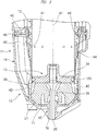
FIG. 1 is a longitudinal cross-sectional view showing an overall configuration of a driver according to an embodiment; -
FIG. 2 is a cross-sectional view showing an internal structure of a head cover of the driver; -
FIG. 3 is a cross-sectional view showing an internal structure of a cylinder of the driver; -
FIG. 4 is a cross-sectional view showing a state in which a first mode is selected in a first specific example of a switching mechanism provided in the deriver; -
FIG. 5 is a cross-sectional view showing a part ofFIG. 2 ; -
FIG. 6 is a block diagram showing a control system of the driver; -
FIG. 7 is a cross-sectional view showing a state in which a second mode is selected in the first specific example of the switching mechanism; -
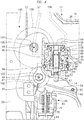
FIG. 8 is a cross-sectional view showing a second specific example of a switching mechanism provided in a driver; -
FIG. 9 is a cross-sectional view showing a state in which a second gear and a clutch are released from each other in the second specific example of the switching mechanism; -
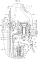
FIG. 10 is a cross-sectional view showing a state in which the first mode is selected in the second specific example of the switching mechanism; -
FIG. 11 is a cross-sectional view showing a state in which the first mode is selected and then an operation force is applied to a trigger in the second specific example of the switching mechanism; -
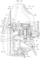
FIG. 12 is a cross-sectional view showing a state in which the second mode is selected in the second specific example of the switching mechanism; -
FIG. 13 is a cross-sectional view showing a state in which the second mode is selected and then an operation force is applied to a push lever in the second specific example of the switching mechanism; and -
FIG. 14 is a cross-sectional view showing a state in which the second gear and the clutch are engaged with each other in the second specific example of the switching mechanism. - Next, some representative drivers among the drivers according to the embodiments included in the present invention will be described with reference to the drawings.
- A driver according to an embodiment will be described with reference to
FIG. 1 . Adriver 10 includes amain body 11, acylinder 12, astriking portion 13, atrigger 14, anejection portion 15, and apush lever 16. Also, amagazine 17 is attached to thedriver 10. Themain body 11 has atubular body portion 18, ahead cover 21 fixed to thebody portion 18, and ahandle 19 connected to thebody portion 18. The handle 19 projects from an outer surface of thebody portion 18. - A
pressure accumulation chamber 20 is formed across an inside of thehandle 19, an inside of thebody portion 18, and an inside of thehead cover 21. An air hose is connected to thehandle 19. Compressed air as compressed gas is supplied into thepressure accumulation chamber 20 through the air hose. Thecylinder 12 is provided in thebody portion 18. Thehead cover 21 has an outertubular portion 22, an innertubular portion 23, and anexhaust passage 24. The outertubular portion 22 and the innertubular portion 23 are arranged concentrically about a center line A1. The innertubular portion 23 is provided inside the outertubular portion 22. - A
head valve 31 is provided in thehead cover 21. Thehead valve 31 has a cylindrical shape and is arranged between the outertubular portion 22 and the innertubular portion 23. Thehead valve 31 is movable in the direction of the center line A1 of thecylinder 12.Sealing members head valve 31. Acontrol chamber 27 is formed between the outertubular portion 22 and the innertubular portion 23. The sealingmembers control chamber 27. A biasingmember 28 is provided in thecontrol chamber 27. The biasingmember 28 is, for example, a metal compression coil spring. - A
stopper 29 is provided in thehead cover 21. Thestopper 29 is made of, for example, synthetic rubber, and a part of thestopper 29 is arranged inside the innertubular portion 23. Apassage 30 is formed between the innertubular portion 23 and thestopper 29, and thepassage 30 is connected to theexhaust passage 24. Theexhaust passage 24 is connected to an outside B1 of themain body 11. - The
cylinder 12 is fixed to thebody portion 18 so as to be positioned in the direction of the center line A1. In thecylinder 12, avalve seat 32 is attached to an end portion of thecylinder 12 that is closest to thehead valve 31 in the direction of the center line A1. Thevalve seat 32 has an annular shape and is made of synthetic rubber. Aport 33 is formed between thehead valve 31 and thevalve seat 32. - The
head valve 31 is constantly biased in a direction away from thevalve seat 32 by the pressure from thepressure accumulation chamber 20. Thehead valve 31 is biased in the direction away from thevalve seat 32 by the pressure of thecontrol chamber 27. The biasingmember 28 biases thehead valve 31 toward thevalve seat 32 in the direction of the center line A1. When thehead valve 31 is pressed to thevalve seat 32, thehead valve 31 closes theport 33. When thehead valve 31 is separated from thevalve seat 32, thehead valve 31 opens theport 33. - The
striking portion 13 includes apiston 34 and adriver blade 35 fixed to thepiston 34. Thepiston 34 is arranged in thecylinder 12, and thepiston 34 is movable in the direction of the center line A1. A sealingmember 100 is attached to an outer peripheral surface of thepiston 34. Anupper piston chamber 36 is formed between thestopper 29 and thepiston 34. When thehead valve 31 opens theport 33, thepressure accumulation chamber 20 is connected to theupper piston chamber 36. When thehead valve 31 closes theport 33, thepressure accumulation chamber 20 is disconnected from theupper piston chamber 36. - The
ejection portion 15 is fixed to an end portion of thebody portion 18 on a side opposite to thehead cover 21 in the direction of the center line A1. - As shown in
FIG. 1 andFIG. 3 , abumper 37 is provided in thecylinder 12. Thebumper 37 is arranged at a position closest to theejection portion 15 in the direction of the center line A1 in thecylinder 12. Thebumper 37 is made of synthetic rubber or silicone rubber. Thebumper 37 has ashaft hole 38, and thedriver blade 35 is movable in theshaft hole 38 in the direction of the center line A1. In thecylinder 12, alower piston chamber 39 is formed between thepiston 34 and thebumper 37. The sealingmember 100 hermetically disconnects thelower piston chamber 39 and theupper piston chamber 36. - A
holder 40 is provided in thebody portion 18. Theholder 40 has a tubular shape. Theholder 40 is concentric with thecylinder 12 and is arranged outside thecylinder 12.Passages cylinder 12 in the radial direction are provided. Thepassage 42 is disposed between thepassage 41 and theejection portion 15 in the direction of the center line A1. Areturn air chamber 43 is formed between the outer surface of thecylinder 12 and thebody portion 18. Thepassage 41 connects thelower piston chamber 39 and thereturn air chamber 43. Acheck valve 44 is provided on thecylinder 12. Thecheck valve 44 opens thepassage 41 when the air in thecylinder 12 is to flow into thereturn air chamber 43. Thecheck valve 44 closes thepassage 41 when the air in thereturn air chamber 43 is to flow into thecylinder 12. - The
passage 42 constantly connects thereturn air chamber 43 and thelower piston chamber 39. Compressed air is enclosed throughout thelower piston chamber 39 and thereturn air chamber 43. A sealingmember 45 is provided between theholder 40 and thebody portion 18, and a sealingmember 46 is provided between theholder 40 and thecylinder 12. The sealingmembers pressure accumulation chamber 20 and thereturn air chamber 43 from each other. - As shown in
FIG. 4 , thetrigger 14 is supported by themain body 11 via asupport shaft 47 and a boss portion 103. The boss portion 103 has a columnar shape, and the boss portion 103 is rotatable with respect to themain body 11 about a center line A4. A center of thesupport shaft 47 is disposed at a position eccentric from the center line A4. Afirst gear 105 is attached to the boss portion 103. Thefirst gear 105 is rotatable about the center line A4 together with the boss portion 103. - A
mode selection member 84 is attached to the boss portion 103. A worker operates themode selection member 84 to select a driving mode. The driving mode includes a first mode and a second mode. Themode selection member 84 is, for example, a lever or a knob. Themode selection member 84 has a first operation position corresponding to the first mode and a second operation position corresponding to the second mode. The first operation position and the second operation position are positions of themode selection member 84 in the rotation direction and are different positions from each other. - When the worker applies an operation force to the
mode selection member 84, theboss portion 102 and thefirst gear 105 rotate about the center line A4. When theboss portion 102 rotates, thesupport shaft 47 revolves about the center line A4. When the worker releases the operation force to themode selection member 84, theboss portion 102 stops. - The worker holds the
handle 19 by hand and applies or releases an operation force to or from thetrigger 14 with a finger. Thetrigger 14 can be actuated within a range of a predetermined angle about thesupport shaft 47. A biasing member that biases thetrigger 14 is provided. The biasing member biases thetrigger 14 clockwise about thesupport shaft 47 inFIG. 4 . The biasing member is, for example, a metal spring. Atubular holder 48 is attached to themain body 11. Theholder 48 has aguide hole 82 and asupport portion 83. Thetrigger 14 biased by the biasing member comes into contact with thesupport portion 83 and is stopped at an initial position. - An
arm 49 is attached to thetrigger 14. Thearm 49 can be actuated with respect to thetrigger 14 about asupport shaft 50 within a range of a predetermined angle. Thesupport portion 83 is disposed between thesupport shaft 47 and thesupport shaft 50 in the length direction of thetrigger 14. Thesupport shaft 50 is provided in thetrigger 14, and thesupport shaft 50 is provided at a position different from thesupport shaft 47. A biasing member that biases thearm 49 about thesupport shaft 50 is provided. The biasing member biases thearm 49 counterclockwise inFIG. 4 . The biasing member is, for example, a metal spring. Thearm 49 biased by the biasing member comes into contact with thesupport portion 83 and is stopped at an initial position. - A
trigger valve 51 is provided at a connection portion between thebody portion 18 and thehandle 19. Thetrigger valve 51 has aplunger 52, afirst body 53, asecond body 54, avalve body 55, and a biasingmember 69. Thefirst body 53 and thesecond body 54 both have a tubular shape, and thefirst body 53 and thesecond body 54 are arranged concentrically about a center line A2. Thevalve body 55 is disposed across an inside of thefirst body 53 and an inside of thesecond body 54. Apassage 56 is formed in thefirst body 53. - Further, the
handle 19 has apassage 58, and thepassage 58 connects thepressure accumulation chamber 20 and the inside of thefirst body 53. A sealing member 59 that seals between thefirst body 53 and themain body 11 is provided. Thesecond body 54 has apassage 60 and ashaft hole 54A. Thepassage 60 is connected to the outside B1 of themain body 11. Thesecond body 54 has aspace 64 connected to theshaft hole 54A. -
Sealing members valve body 55. Thevalve body 55 has ashaft hole 65. The sealingmember 63 hermetically seals thespace 64. Theplunger 52 is disposed across an inside of the shaft holes 54A and 65.Sealing members plunger 52. Aflange 68 projecting from the outer peripheral surface of theplunger 52 is provided. The biasingmember 69 is provided in theshaft hole 65. The biasingmember 69 is, for example, a compression spring, and the biasingmember 69 biases theplunger 52 toward thearm 49 in the direction of the center line A2. - A
first ventilation passage 57 and asecond ventilation passage 106 are provided. Thefirst ventilation passage 57 connects thecontrol chamber 27 and thepassage 56. Thefirst ventilation passage 57 is provided in thebody portion 18. As shown inFIG. 4 , afirst valve 107 is provided in thebody portion 18. Thefirst valve 107 opens and closes thefirst ventilation passage 57. Thefirst valve 107 has a columnar shape, and thefirst valve 107 is rotatably supported by thebody portion 18 about a center line A5. Aconnection passage 108 that penetrates thefirst valve 107 in the radial direction is provided. - A
second gear 109 is attached to thefirst valve 107. Thesecond gear 109 is arranged concentrically with thefirst valve 107, and thesecond gear 109 and thefirst valve 107 can rotate integrally. Thesecond gear 109 meshes with thefirst gear 105. When an operation force is applied to themode selection member 84 and thefirst gear 105 is rotated, the rotational force of thefirst gear 105 is transmitted to thesecond gear 109. When thefirst gear 105 stops, thesecond gear 109 stops. Thefirst valve 107 is rotated or stopped together with thesecond gear 109. When thefirst valve 107 is stopped, theconnection passage 108 is connected to or disconnected from thefirst ventilation passage 57. The state where theconnection passage 108 and thefirst ventilation passage 57 are connected is the state where thefirst valve 107 is open. The state where theconnection passage 108 and thefirst ventilation passage 57 are disconnected is the state where thefirst valve 107 is closed. - A
switching mechanism 135 is made up of themode selection member 84, theboss portion 102, thefirst gear 105, and thesecond gear 109. Theswitching mechanism 135 is configured to switch the actuation and the stop of thefirst valve 107. - The
second ventilation passage 106 is disposed in parallel to thefirst ventilation passage 57. Thesecond ventilation passage 106 is provided across thebody portion 18 and thehead cover 21. As shown inFIG. 5 , asolenoid valve 110 is provided in thehead cover 21. Thesolenoid valve 110 has avalve body 111, aplunger 112, acoil 113, and a biasingmember 114. Thevalve body 111 has aport 115 and theplunger 112 can be actuated. Theplunger 112 is made of a magnetic material. The biasingmember 114 is, for example, a metal compression spring. When the power supply to thesolenoid valve 110 is stopped, theplunger 112 biased by the force of the biasingmember 114 comes into contact with thevalve body 111 and is stopped there, and theplunger 112 closes theport 115. Namely, thesolenoid valve 110 closes thesecond ventilation passage 106. When power is supplied to thesolenoid valve 110, theplunger 112 is actuated by the magnetic attraction force against the force of the biasingmember 114, and theplunger 112 opens theport 115. Namely, thesolenoid valve 110 opens thesecond ventilation passage 106. - The
ejection portion 15 shown inFIG. 1 is made of, for example, metal or non-ferrous metal. Theejection portion 15 has atubular portion 70 and aflange 71 connected to an outer peripheral surface of thetubular portion 70. Theflange 71 is fixed to thebody portion 18 by a fixing element. Thetubular portion 70 has anejection path 72. The center line A1 is located in theejection path 72, and thedriver blade 35 is movable in theejection path 72 in the direction of the center line A1. - The
magazine 17 is fixed to theejection portion 15. Themagazine 17 stores nails 73. Themagazine 17 has a feeder 74, and the feeder 74 sends thenails 73 in themagazine 17 to theejection path 72. - A
transmission member 75 connected so as to be able to transmit power to thepush lever 16 is provided. As shown inFIG. 4 , thetransmission member 75 is supported by theholder 48. A part of thetransmission member 75 is disposed in theguide hole 82. Thetransmission member 75 is movable with respect to theholder 48 in the direction of a center line A3. The center line A3 is parallel to the center line A2. When thetransmission member 75 comes into contact with thearm 49, the actuation force of thepush lever 16 is transmitted to thearm 49. When thetransmission member 75 is separated from thearm 49, the actuation force of thepush lever 16 is not transmitted to thearm 49. Thetransmission member 75 is biased by a biasingmember 76 in the direction away from thearm 49. The biasingmember 76 is, for example, a metal spring. -
FIG. 6 is a block diagram showing a control system of thedriver 10. Thedriver 10 includes atrigger switch 92, apush lever switch 93, amicroswitch 91, acontrol unit 94, apower source 96, and aswitch circuit 97. Thepower source 96 is connected to the solenoid valve via anelectric circuit 99. Anelectric circuit 132 is provided between thepower source 96 and thecontrol unit 94, and themicroswitch 91 connects and disconnects theelectric circuit 132. When themode selection member 84 is located at the first operation position, themicroswitch 91 disconnects theelectric circuit 132. When themode selection member 84 is located at the second operation position, themicroswitch 91 connects theelectric circuit 132. - The
power source 96 is an element that applies a voltage to thecontrol unit 94 and thesolenoid valve 110, and a secondary battery that can be charged and discharged can be used for thepower source 96. Thepower source 96 can be attached to, for example, thehandle 19 or themagazine 17. - The
control unit 94 is a microcomputer including an input interface, an output interface, a storage unit, an arithmetic processing unit, and atimer 98. Thecontrol unit 94 is activated when theelectric circuit 132 is connected and a voltage is applied from thepower source 96. When theelectric circuit 132 is disconnected, thecontrol unit 94 is stopped because no voltage is applied from thepower source 96. - The
trigger switch 92 outputs different signals depending on whether the operation force is applied to thetrigger 14 or the operation force to thetrigger 14 is released. Thepush lever switch 93 outputs different signals depending on whether thepush lever 16 is pressed to aworkpiece 77 or is separated from it. Thetrigger switch 92 and thepush lever switch 93 may be either contact switches or non-contact switches. The signals from thetrigger switch 92 and thepush lever switch 93 are input to thecontrol unit 94. - The
control unit 94 processes the signal of thetrigger switch 92 and detects whether the operation force is applied to thetrigger 14 or the operation force to thetrigger 14 is released. Thecontrol unit 94 processes the signal of thepush lever switch 93 and detects whether thepush lever 16 is in contact with theworkpiece 77 or thepush lever 16 is separated from theworkpiece 77. - The
switch circuit 97 is provided in theelectric circuit 99. Theswitch circuit 97 includes, for example, a plurality of field effect transistors. Thecontrol unit 94 controls theswitch circuit 97 to connect or disconnect theelectric circuit 99. - Next, an example in which the
nail 73 shown inFIG. 1 is driven into theworkpiece 77 with use of thedriver 10 will be described. In the state where the worker releases the operation force to thetrigger 14 and the push lever, the worker operates themode selection member 84 to select the first mode or the second mode. In accordance with the operation position of themode selection member 84, the position of thesupport shaft 47 with respect to thetransmission member 75 changes. When the operation position of themode selection member 84 changes, the position of thesupport shaft 47 with respect to thetransmission member 75 changes in the direction intersecting the center line A3. Therefore, the position of the tip of thearm 49 with respect to thetransmission member 75 changes. - An example in which the worker operates the
mode selection member 84 to select the first mode will be described with reference toFIG. 4 andFIG. 5 . When the first mode is selected, themicroswitch 91 disconnects theelectric circuit 132, and thus thecontrol unit 94 is stopped. When the operation force to thetrigger 14 is released and thepush lever 16 is separated from theworkpiece 77 in the state where the first mode is selected, thetrigger valve 51, thehead valve 31, and thestriking portion 13 are in the following initial states. - The
trigger 14 is in contact with thesupport portion 83 and is stopped at the initial position. Further, thearm 49 is in contact with thesupport portion 83 and is stopped at the initial position. The tip of thearm 49 is within the actuation range of thetransmission member 75. Thetransmission member 75 is stopped at the initial position separated from thearm 49. In addition, thearm 49 is separated from theplunger 52. Namely, no actuation force is applied from thearm 49 to theplunger 52. - The
flange 68 is pressed to thesecond body 54 by the biasingmember 69. Thevalve body 55 is biased by the biasing force of the biasingmember 69 in the direction away from thearm 49, and the sealingmember 62 is pressed to thefirst body 53, so that thevalve body 55 is stopped at the initial position. - The sealing
member 62 disconnects thepassage 56 and thepassage 60. The sealingmember 61 is separated from thefirst body 53, and thepressure accumulation chamber 20 is connected to thecontrol chamber 27 via thepassage 58, thepassage 56, and thefirst ventilation passage 57. The sealingmember 66 is separated from thevalve body 55, and thepressure accumulation chamber 20 is connected to thespace 64 via thepassage 58 and theshaft hole 65. The sealingmember 67 seals theshaft hole 54A to disconnect thespace 64 and the outside B1. - On the other hand, when the worker selects the first mode, the
first valve 107 is in the state of opening thefirst ventilation passage 57. The compressed air of thepressure accumulation chamber 20 is supplied to thecontrol chamber 27 through thefirst ventilation passage 57. In addition, when the first mode is selected, thecontrol unit 94 is stopped, so that no power is supplied to thesolenoid valve 110. Therefore, thesolenoid valve 110 closes thesecond ventilation passage 106 as shown inFIG. 5 . - As shown in
FIG. 2 , thehead valve 31 is pressed to thevalve seat 32 by the biasing force of the biasingmember 28 and the pressure of thecontrol chamber 27. Thehead valve 31 closes theport 33. Also, the inner peripheral surface of thehead valve 31 is separated from the outer peripheral end of thestopper 29. Theupper piston chamber 36 is connected to the outside B1 via thepassage 30 and theexhaust passage 24. Therefore, the pressure of theupper piston chamber 36 is equal to the atmospheric pressure and is lower than the pressure of thelower piston chamber 39. Accordingly, thepiston 34 is stopped while being pressed to thestopper 29 by the pressure of thelower piston chamber 39. As described above, the strikingportion 13 is stopped at the top dead center shown inFIG. 1 andFIG. 2 . - When the worker presses the
push lever 16 to theworkpiece 77 in the state where the worker selects the first mode and does not apply the operation force to thetrigger 14, thecontrol unit 94 detects that the operation force is applied to thepush lever 16. Also, the actuation force of thepush lever 16 is transmitted to thetransmission member 75. Thetransmission member 75 is actuated toward thetrigger valve 51 from the initial position against the biasing force of the biasingmember 76. Then, thetransmission member 75 projects from thesupport portion 83, and the actuation force of thetransmission member 75 is transmitted to thearm 49. Thearm 49 is actuated clockwise about thesupport shaft 50, and when thetransmission member 75 is stopped at the actuated position, thearm 49 is also stopped at the intermediate position. In this state, the actuation force of thearm 49 is not transmitted to theplunger 52, and theplunger 52 is stopped at the initial position. - When the worker maintains the state of pressing the
push lever 16 to theworkpiece 77 and applies an operation force to thetrigger 14, thetrigger 14 is actuated counterclockwise about thesupport shaft 47. Then, thearm 49 is actuated with thetransmission member 75 as a fulcrum, and the actuation force of thearm 49 is transmitted to theplunger 52. Theplunger 52 is actuated from the initial position against the biasing force of the biasingmember 69. When thetrigger 14 comes into contact with themain body 11 and is stopped at the actuated position, thearm 49 is stopped at the actuated position and theplunger 52 is stopped at the actuated position. - When the
plunger 52 is stopped at the actuated position, the sealingmember 66 seals theshaft hole 65. The sealingmember 67 moves to thespace 64, and thespace 64 and the outside B1 are connected via theshaft hole 54A. Therefore, thevalve body 55 is actuated by the pressure of the compressed air of thepressure accumulation chamber 20 against the force of the biasingmember 69, and the sealingmember 61 disconnects thepressure accumulation chamber 20 and thepassage 56. Also, the sealingmember 62 separates from thefirst body 53, and thepassage 56 and thepassage 60 are connected. Therefore, the compressed air of thecontrol chamber 27 is discharged to the outside B1 through thefirst ventilation passage 57, thepassage 56, and thepassage 60, and the pressure of thecontrol chamber 27 becomes equal to the atmospheric pressure. - When the pressure of the
control chamber 27 becomes equal to the atmospheric pressure, thehead valve 31 is actuated by the pressure of thepressure accumulation chamber 20 against the biasing force of the biasingmember 28, and thehead valve 31 is separated from thevalve seat 32 and is stopped there. Thus, theport 33 is opened, and thepressure accumulation chamber 20 is connected to theupper piston chamber 36 via theport 33. Further, thehead valve 31 comes into contact with thestopper 29, and thehead valve 31 disconnects theupper piston chamber 36 and theexhaust passage 24. Then, the compressed air of thepressure accumulation chamber 20 is supplied to theupper piston chamber 36, and the pressure of theupper piston chamber 36 rises. When the pressure of theupper piston chamber 36 becomes higher than the pressure of thelower piston chamber 39, the strikingportion 13 is actuated from the top dead center to the bottom dead center in the direction of the center line A1, and thedriver blade 35 strikes thenail 73 in theejection path 72. Thestruck nail 73 is driven into theworkpiece 77. - After the
striking portion 13 drives thenail 73 into theworkpiece 77, thepiston 34 collides with thebumper 37 as shown inFIG. 3 , and thebumper 37 absorbs a part of the kinetic energy of thestriking portion 13. The position of thestriking portion 13 at the time when thepiston 34 collides with thebumper 37 is the bottom dead center. Also, thecheck valve 44 opens thepassage 41 while thestriking portion 13 is being actuated from the top dead center to the bottom dead center, and the compressed air of thelower piston chamber 39 flows into thereturn air chamber 43 via thepassage 41. - When the worker separates the
push lever 16 from theworkpiece 77, thetransmission member 75 is actuated by the biasing force of the biasingmember 76 and is stopped at the initial position. Also, when the worker releases the operation force to thetrigger 14, thetrigger 14 returns from the actuated position to the initial position, and thearm 49 returns from the actuated position to the initial position and is stopped there by the biasing force of the biasing member 81. - Further, the
plunger 52 returns from the actuated position to the initial position, and thehead valve 31 returns to the initial state to close theport 33. Then, the pressure of theupper piston chamber 36 becomes equal to the atmospheric pressure, and thepiston 34 is actuated from the bottom dead center toward the top dead center by the pressure of thelower piston chamber 39. Further, the compressed air of thereturn air chamber 43 flows into thelower piston chamber 39 through thepassage 42, and thestriking portion 13 returns to the top dead center and is stopped there. - Furthermore, also in the case where the worker releases the operation force to the
trigger 14, slides thepush lever 16 on theworkpiece 77 and stops it, and then applies the operation force to thetrigger 14 again while maintaining the state of pressing thepush lever 16 to theworkpiece 77, the strikingportion 13 is actuated in the direction of driving thenail 73 according to the same principle as described above. - On the other hand, even when the worker separates the
push lever 16 from theworkpiece 77 and presses thepush lever 16 to theworkpiece 77 again while maintaining the state in which the worker applies the operation force to thetrigger 14, the actuation force of thetransmission member 75 is not transmitted to thearm 49. Namely, the strikingportion 13 is held in a state of being stopped at the top dead center. - When the worker operates the
mode selection member 84 to select the second mode, themicroswitch 91 connects theelectric circuit 132 and a voltage is applied from thepower source 96 to thecontrol unit 94, so that thecontrol unit 94 is activated. Further, as shown inFIG. 7 , thefirst valve 107 closes thefirst ventilation passage 57. When the worker applies an operation force to thetrigger 14 in the state where the worker separates thepush lever 16 from theworkpiece 77, thetrigger 14 is actuated counterclockwise from the initial position against the biasing force of the biasing member 80 and is stopped at the actuated position. Further, thetimer 98 starts measuring the elapsed time from when the operation force is applied to thetrigger 14. Further, thearm 49 is actuated with thesupport portion 83 as a fulcrum. However, since thepush lever 16 is not pressed to theworkpiece 77, the actuation force of thearm 49 is not transmitted to theplunger 52, and theplunger 52 is stopped at the initial position. - When the
push lever 16 is pressed to theworkpiece 77 in the state where the operation force is applied to thetrigger 14, theplunger 52 is actuated from the initial position and is stopped at the actuated position. Namely, thetrigger valve 51 is in the actuated state in which thepressure accumulation chamber 20 and thepassage 56 are disconnected and thepassage 56 is connected to the outside B1 via thepassage 60. - Here, the
control unit 94 determines whether the elapsed time from when the operation force is applied to thetrigger 14 to when the operation force is applied to thepush lever 16 is within a predetermined time or exceeds the predetermined time. The predetermined time is, for example, 3 seconds, and thecontrol unit 94 stores the predetermined time in advance. - When the
control unit 94 determines that the elapsed time from when the operation force is applied to thetrigger 14 to when the operation force is applied to thepush lever 16 is within the predetermined time, thecontrol unit 94 controls theswitch circuit 97 to supply power to thesolenoid valve 110, thereby controlling thesolenoid valve 110 to be in the state of opening thesecond ventilation passage 106. - Here, as the control by the
control unit 94 to supply power to thesolenoid valve 110, the first control or the second control can be selected. The first control is to start the power supply to thesolenoid valve 110 when the operation force is applied to thetrigger 14 and constantly supply the power to thesolenoid valve 110 within a predetermined time. The second control is not to supply power to thesolenoid valve 110 when the operation force is applied to thetrigger 14 and supply power to thesolenoid valve 110 when the operation force is applied to thepush lever 16 to press it to theworkpiece 77 within a predetermined time. - In this manner, when the
push lever 16 is pressed to theworkpiece 77 in the state where the second mode is selected and the operation force is applied to thetrigger 14, thesolenoid valve 110 is in the state of opening thesecond ventilation passage 106. Therefore, the compressed air of thecontrol chamber 27 is discharged to the outside B1 via thesecond ventilation passage 106, thepassage 56, and thepassage 60, and thestriking portion 13 is actuated in the direction of striking thenail 73 from the top dead center. Note that thetimer 98 resets the measured elapsed time and newly starts measuring the elapsed time. - Thereafter, in the state where the second mode is selected and the operation force is applied to the
trigger 14, the worker can drive thenail 73 into theworkpiece 77 by performing the operation of pressing thepush lever 16 to theworkpiece 77 and separating thepush lever 16 from theworkpiece 77. - On the other hand, when the elapsed time from when the operation force is applied to the
trigger 14 exceeds the predetermined time, thecontrol unit 94 controls theswitch circuit 97 to stop the power supply to thesolenoid valve 110. Namely, thecontrol unit 94 controls thesolenoid valve 110 to be in the state of closing thesecond ventilation passage 106. - Here, as the control by the
control unit 94 to stop the power supply to thesolenoid valve 110, the third control or the fourth control can be selected. The third control is to start the power supply to thesolenoid valve 110 when an operation force is applied to thetrigger 14 and stop the power supply to thesolenoid valve 110 when a predetermined time has elapsed. The fourth control is not to supply power to thesolenoid valve 110 when the operation force is applied to thetrigger 14 and not supply power to thesolenoid valve 110 even after a predetermined time has elapsed. - Therefore, when the
push lever 16 is pressed to theworkpiece 77 after a predetermined time has elapsed from when the second mode is selected and the operation force is applied to thetrigger 14, thesolenoid valve 110 is in the state of closing thesecond ventilation passage 106. Accordingly, the compressed air of thecontrol chamber 27 is not discharged to the outside B1 via thesecond ventilation passage 106. Also, when the second mode is selected, thefirst valve 107 is in the state of closing thefirst ventilation passage 57. Thus, the strikingportion 13 is stopped at the top dead center, and thestriking portion 13 does not strike thenail 73. Note that, when the worker separates thepush lever 16 from theworkpiece 77 and releases the operation force to thetrigger 14, thetimer 98 resets the measured elapsed time. - As described above, in the
driver 10, thefirst ventilation passage 57 through which the compressed air is discharged from thecontrol chamber 27 to the outside B1 when the first mode is selected and thesecond ventilation passage 106 through which the compressed air is discharged from thecontrol chamber 27 to the outside B1 when the second mode is selected are separately provided. Therefore, if thesolenoid valve 110 is not actuated normally for some reason and thesecond ventilation passage 106 is in a closed state, thefirst valve 107 is in the state of opening thefirst ventilation passage 57 when themode selection member 84 is operated to select the first mode. As a result, in thedriver 10, the strikingportion 13 is actuated in the first mode and can strike thenail 73. - Further, when the worker operates the
mode selection member 84 to select the second mode and the worker presses thepush lever 16 to theworkpiece 77 and then applies an operation force to thetrigger 14, thetrigger valve 51 becomes the actuated state from the initial state. Therefore, the compressed air of thecontrol chamber 27 is discharged to the outside B1 via thesecond ventilation passage 106, thepassage 56, and thepassage 60, and thestriking portion 13 strikes thenail 73. Note that, when the worker operates themode selection member 84 to select the second mode, thetimer 98 does not start measuring the elapsed time even if the worker presses thepush lever 16 to theworkpiece 77 and then applies an operation force to thetrigger 14. - As described above, the
first ventilation passage 57 through which compressed air is discharged when the first mode is selected and thesecond ventilation passage 106 through which compressed air is discharged when the second mode is selected are provided separately. This is the structure in which thefirst ventilation passage 57 can be mechanically opened and closed by transmitting the actuation force of themode selection member 84 to thefirst valve 107 to actuate thefirst valve 107. Therefore, even in the state where thestriking portion 13 cannot be actuated in the direction of striking thenail 73 like the case where the power cannot be supplied to thesolenoid valve 110 though thepower source 96 has power in the state where the second mode is selected or the case where thepower supply 96 has no power, the strikingportion 13 can be actuated in the direction of striking thenail 73 by selecting the first mode. - Furthermore, when the first mode is selected, no voltage is applied from the
power source 96 to thecontrol unit 94, and thecontrol unit 94 is stopped. In addition, when the second mode is selected, a voltage is applied from thepower source 96 to thecontrol unit 94, and thecontrol unit 94 is activated. Therefore, the amount of consumed power of thepower source 96 can be reduced as much as possible. - A second specific example of the switching mechanism that can be provided in the
driver 10 ofFIG. 1 will be described with reference toFIG. 8 andFIG. 9 . Thetrigger 14 is attached to asupport shaft 117, and themain body 11 rotatably supports thesupport shaft 117 about a center line A6. Thesupport shaft 117 does not move in the direction intersecting the center line A6. Afirst gear 118 is provided on thesupport shaft 117. Thefirst valve 107 is attached to avalve shaft 119. Thevalve shaft 119 and thefirst valve 107 are rotatably supported by thebody portion 18 about the center line A5. Thevalve shaft 119 is biased clockwise by a biasingmember 120 inFIG. 8 . The biasingmember 120 is, for example, a metal torsion spring. Arotation prevention member 121 is attached to thevalve shaft 119. Anengagement portion 122 protruding from an outer surface of therotation prevention member 121 is provided. Astopper 131 is provided on thebody portion 18, and therotation prevention member 121 and thevalve shaft 119 are stopped when theengagement portion 122 is in contact with thestopper 131. - A fixing
member 123 is attached to thevalve shaft 119, and a clutch 124 is also attached thereto. The clutch 124 is fixed to thevalve shaft 119. The clutch 124 has anengagement portion 128 disposed along the rotation direction of thevalve shaft 119. Asecond gear 125 is attached to thevalve shaft 119. Thesecond gear 125 is movable in the direction of the center line A5 with respect to thevalve shaft 119 and is rotatable with respect to thevalve shaft 119. Further, athird gear 126 is provided, and thethird gear 126 meshes with thefirst gear 118 and thesecond gear 125. - Further, a biasing
member 127 is provided between the fixingmember 123 and thesecond gear 125. The biasingmember 127 biases thesecond gear 125 toward the clutch 124 in the direction of the center line A5. The biasingmember 127 is, for example, a metal compression spring. Thesecond gear 125 is biased by the biasingmember 127 while meshing with thethird gear 126. Thesecond gear 125 has anengagement portion 129 disposed along the rotation direction. Theengagement portion 128 of thesecond gear 125 and theengagement portion 129 of the clutch 124 can be engaged with and released from each other. Namely, thesecond gear 125 and the clutch 124 can be engaged with and released from each other. - Furthermore, a
push lever arm 130 is provided. Thepush lever arm 130 is coupled to thepush lever 16, and thepush lever arm 130 can be actuated together with thepush lever 16 in the direction of the center line A3. The tip of thepush lever arm 130 can be engaged with and released from theengagement portion 122. Thesupport shaft 117, thefirst gear 118, thesecond gear 125, thethird gear 126, the clutch 124, thevalve shaft 119, therotation prevention member 121, and thepush lever arm 130 constitute aswitching mechanism 136. Theswitching mechanism 136 is configured to switch the actuation and the stop of thefirst valve 107. Theswitching mechanism 136 can be provided in thedriver 10 ofFIG. 1 . - The
driver 10 shown inFIG. 8 can use the control system shown inFIG. 6 . In this case, themode selection member 84 is not provided. Themicroswitch 91 is disposed on the outer peripheral side of therotation prevention member 121 as shown inFIG. 8 . When therotation prevention member 121 rotates, theengagement portion 12 comes into contact with or separates from themicroswitch 91. Themicroswitch 91 connects or disconnects theelectric circuit 132 depending on the position of therotation prevention member 121 in the rotation direction. - When the worker does not apply an operation force to any of the
trigger 14 and thepush lever 16, theengagement portion 122 comes into contact with thestopper 131 and therotation prevention member 121 and thefirst valve 107 are stopped as shown inFIG. 8 . Thefirst valve 107 is in the state of opening thefirst ventilation passage 57. Further, thepush lever arm 130 is stopped at the initial position shown inFIG. 8 . Thepush lever arm 130 stopped at the initial position is separated from theengagement portion 122 and is located outside the actuation range of theengagement portion 122. Further, thesecond gear 125 and the clutch 124 are engaged. Also, when theengagement portion 122 is in contact with thestopper 131, theengagement portion 122 is separated from themicroswitch 91, and thecontrol unit 94 is stopped. Therefore, power is not supplied from thepower source 96 to thesolenoid valve 110, and thesolenoid valve 110 closes thesecond ventilation passage 106. - The first mode is a usage mode of the
driver 10 in which the worker presses thepush lever 16 to theworkpiece 77 and then applies an operation force to thetrigger 14. When the worker presses thepush lever 16 to theworkpiece 77, thepush lever arm 130 engages with theengagement portion 122 and is stopped as shown inFIG. 9 andFIG. 10 . Further, thetransmission member 75 moves from the initial position to the actuated position, and thetransmission member 75 rotates thearm 49 and is stopped. - Then, when the worker applies an operation force to the
trigger 14, thetrigger 14 rotates counterclockwise as shown inFIG. 11 , and thesupport shaft 117 rotates counterclockwise. When the rotational force of thesupport shaft 117 is transmitted to thethird gear 126, thethird gear 126 rotates clockwise, and thesecond gear 125 receives the counterclockwise rotational force. - When the counterclockwise rotational force is transmitted to the
second gear 125 in the state where thepush lever arm 130 is engaged with theengagement portion 122 of therotation prevention member 121 and the rotation of thevalve shaft 119 is blocked, the engagement reaction force between theengagement portion 129 and theengagement portion 128 causes thesecond gear 125 to move in the direction away from the clutch 124 against the biasing force of the biasingmember 127, and theengagement portion 129 and theengagement portion 128 are released. Therefore, thevalve shaft 119 maintains the stopped state, and thefirst valve 107 is in the state of opening thefirst ventilation passage 57. - Further, when an operation force is applied to the
trigger 14 and thetrigger valve 51 is switched from the initial state to the actuated state, the compressed air of thecontrol chamber 27 is discharged to the outside via thefirst ventilation passage 57, thepassage 56, and thepassage 60. Therefore, the strikingportion 13 is actuated from the top dead center toward the bottom dead center, and thestriking portion 13 strikes thenail 73. - Further, when the worker releases the operation force to the
trigger 14 and separates thepush lever 16 from theworkpiece 77, thepush lever arm 130 is separated from theengagement portion 122 and is stopped at the initial position. Also, thefirst gear 118 rotates clockwise, thethird gear 126 rotates counterclockwise, thesecond gear 125 rotates clockwise, theengagement portion 129 and theengagement portion 128 are engaged, and thesecond gear 125 is stopped. - The second mode is a usage mode of the
driver 10 in which the worker applies an operation force to thetrigger 14 and then presses thepush lever 16 to theworkpiece 77. When the worker applies an operation force to thetrigger 14 as shown inFIG. 12 in the state where thepush lever 16 is separated from theworkpiece 77, the operation force causes thefirst gear 118 to rotate counterclockwise, thethird gear 126 rotates clockwise, and thesecond gear 125 rotates counterclockwise. Since thepush lever arm 130 is located outside the actuation range of theengagement portion 122, thesecond gear 125 does not move in the direction of the center line A5 as shown inFIG. 14 , and the state where theengagement portion 129 and theengagement portion 128 are engaged is maintained. Therefore, the rotational force of thesecond gear 125 is transmitted to thevalve shaft 119 via the clutch 124. Thevalve shaft 119 rotates against the force of the biasingmember 120, and thefirst valve 107 closes thefirst ventilation passage 57. - In addition, the
second gear 125 rotates counterclockwise as shown inFIGs. 8 to 12 , so that theengagement portion 122 comes into contact with themicroswitch 91. Themicroswitch 91 connects theelectric circuit 132, a voltage is applied from thepower source 96 to thecontrol unit 94, thecontrol unit 94 is activated, and thetimer 98 starts measuring the elapsed time from when the operation force is applied to thetrigger 14. - When the worker applies the operation force to the
trigger 14 and then presses thepush lever 16 to theworkpiece 77, thearm 49 is rotated by the actuation force of thetransmission member 75, the rotational force of thearm 49 is transmitted to theplunger 52, and theplunger 52 is stopped in the actuated state shown inFIG. 13 . Then, thevalve body 55 is actuated by the pressure of thepressure accumulation chamber 20, thepressure accumulation chamber 20 and thepassage 56 are disconnected, and thepassage 56 is connected to the outside B1 via thepassage 60. - When the
control unit 94 determines that the elapsed time from when the operation force is applied to thetrigger 14 to when the operation force is applied to thepush lever 16 is within the predetermined time, thecontrol unit 94 controls theswitch circuit 97 to supply power to thesolenoid valve 110, thereby controlling thesolenoid valve 110 to be in the state of opening thesecond ventilation passage 106. Therefore, the compressed air of thecontrol chamber 27 is discharged to the outside via thesecond ventilation passage 106, thepassage 56, and thepassage 60. Thus, the strikingportion 13 is actuated from the top dead center to the bottom dead center and strikes thenail 73. Note that thetimer 98 resets the measured elapsed time and newly starts measuring the elapsed time. - Thereafter, in the state where the operation force is applied to the
trigger 14, the worker can drive thenail 73 into theworkpiece 77 by alternatively repeating the operation of pressing thepush lever 16 to theworkpiece 77 and the operation of separating thepush lever 16 from theworkpiece 77. - On the other hand, when the elapsed time from when the operation force is applied to the
trigger 14 exceeds the predetermined time, thecontrol unit 94 controls theswitch circuit 97 to stop the current supply to thesolenoid valve 110. Namely, thecontrol unit 94 controls thesolenoid valve 110 to be in the state of closing thesecond ventilation passage 106. - Here, as the control by the
control unit 94 to stop the current supply to thesolenoid valve 110, the fifth control or the sixth control can be selected. The fifth control is to start the current supply to thesolenoid valve 110 when an operation force is applied to thetrigger 14 and stop the current supply to thesolenoid valve 110 when a predetermined time has elapsed. The sixth control is not to supply current to thesolenoid valve 110 when the operation force is applied to thetrigger 14 and continues to stop the current supply to thesolenoid valve 110 even after a predetermined time has elapsed. - Therefore, when the
push lever 16 is pressed to theworkpiece 77 after a predetermined time has elapsed from when the operation force is applied to thetrigger 14, thesolenoid valve 110 is in the state of closing thesecond ventilation passage 106. Accordingly, the compressed air of thecontrol chamber 27 is not discharged to the outside B1 via thesecond ventilation passage 106. Also, when the second mode is selected, thefirst valve 107 is in the state of closing thefirst ventilation passage 57. Thus, the strikingportion 13 is stopped at the top dead center, and thestriking portion 13 does not strike thenail 73. Note that, when the worker releases the operation force to thetrigger 14, thesecond gear 125 rotates clockwise inFIG. 12 and is stopped at the position inFIG. 8 . Therefore, themicroswitch 91 disconnects theelectric circuit 132 and thecontrol unit 94 is stopped. Namely, the elapsed time measured by thetimer 98 is reset. - As described above, in the
driver 10 having theswitching mechanism 136, thefirst ventilation passage 57 through which the compressed air is discharged from thecontrol chamber 27 to the outside B1 when the first mode is selected and thesecond ventilation passage 106 through which the compressed air is discharged from thecontrol chamber 27 to the outside B1 when the second mode is selected are separately provided. Therefore, it is possible to obtain the same effect as that of thedriver 10 having theswitching mechanism 135. - The technical meanings of the matters disclosed in the embodiments are as follows. The
upper piston chamber 36 is an example of a pressure chamber. Thenail 73 is an example of a fastener. Thestriking portion 13 is an example of a striking portion. Thetrigger 14 is an example of an operation member. Thepush lever 16 is an example of a contact member. Theport 33 is an example of a passage for supplying compressed gas to the pressure chamber. Thehead valve 31 is an example of a valve body. Thecontrol chamber 27 is an example of a control chamber. Thefirst ventilation passage 57 is an example of a first ventilation passage. Thesecond ventilation passage 106 is an example of a second ventilation passage. Thefirst valve 107, thesolenoid valve 110, and thecontrol unit 94 are an example of an opening/closing mechanism. - The state in which the first mode is selected, the
first valve 107 opens thefirst ventilation passage 57, and thesolenoid valve 110 closes thesecond ventilation passage 106 is an example of a first state. The state in which the second mode is selected, thefirst valve 107 closes thefirst ventilation passage 57, and thesolenoid valve 110 opens thesecond ventilation passage 106 is an example of a second state. The state in which the second mode is selected and thepush lever 16 is separated from theworkpiece 77 within a predetermined time from when the operation force is applied to thetrigger 14, so that thesolenoid valve 110 closes thesecond ventilation passage 106 is an example of a third state. - The
first valve 107 is an example of a first valve. Thesolenoid valve 110 is an example of a second valve. Thetrigger switch 92, thepush lever switch 93, themicroswitch 91, and thecontrol unit 94 are an example of a first driving unit. Themode selection member 84 is an example of a mode selection member. The first operation position and the second operation position of themode selection member 84 are examples of an operation state of the mode selection member. Thetrigger 14, thesupport shaft 47, and thearm 49 are an example of a restriction mechanism. - Applying an operation force to the
trigger 14 is an example of a first operation. Bringing thepush lever 16 into contact with theworkpiece 77 is an example of a second operation. Thetrigger switch 92, thepush lever switch 93, and thecontrol unit 94 are an example of a detection unit. The switchingmechanisms - The driver is not limited to the above-described embodiments, and various modifications can be made without departing from the spirit of the invention. For example, the operation member includes an element that is operated linearly by the application of an operation force other than an element that is rotated by the application of an operation force. The examples of the operation member include a lever, a knob, a button, an arm, and the like.
- The contact member may be not only a member provided independently of an ejection port of an ejection portion, but also a member provided integrally with the ejection port. The ejection port is formed at the end of the ejection portion. Moreover, examples of the contact member include a lever, an arm, a rod, a plunger, and the like. Further, the contact member may have a tubular shape at a portion in contact with the workpiece or have a plate-like shape through the whole in the direction of the center line A1. The contact member includes a member that is actuated against the force of an elastic member when pressed to the workpiece. The structure in which a contact member is actuated when an operation force is applied to the operation member in the state where the contact member is not pressed to the workpiece may also be applicable.
- The control unit or the detection unit may be a single electric component or electronic component, or a unit having a plurality of electric components or a plurality of electronic components. The electric component or the electronic component includes a processor, a control circuit, and a module. The first ventilation passage and the second ventilation passage are paths through which compressed air flows, and include holes, openings, gaps between components, slits, notches, and the like.
- As the compressed gas, inert gas such as nitrogen gas or rare gas may be used instead of the compressed air. The striking portion may have either a structure in which the piston and the driver blade are integrally formed or a structure in which the piston and the driver blade that are separately provided are fixed to each other. The fastener includes a nail having a shaft portion and a head portion as well as a nail having a shaft portion and no head portion. The fastener includes a U-shaped pin, a U-shaped screw, and the like. The fastener includes an arbitrary shape and structure that are inserted into the workpiece and fixed to the workpiece. Actuating the striking portion in the direction of striking the fastener does not matter whether the striking portion strikes the fastener.
- The solenoid valve may be a keep solenoid valve having a permanent magnet instead of the biasing member. In the keep solenoid valve, the plunger is stopped at a predetermined position by the attraction force of the permanent magnet when no power is supplied. When power is supplied to the keep solenoid valve, the plunger is actuated against the attraction force of the permanent magnet.
- Further, by sliding the contact member in contact with the workpiece in the state where the worker selects the first mode and repeating the application and release of the operation force to the operation member while the contact member is in contact with the workpiece, the fastener can be driven by the striking portion.
- Further, in the
driver 10 having themode selection member 84, thecontrol unit 94 may be configured to be activated by applying a voltage from thepower source 96 to thecontrol unit 94 regardless of the state of themicroswitch 91. With this configuration, thecontrol unit 94 can determine that either the first mode or the second mode has been selected at the time when themode selection member 84 is operated. Also, when themode selection member 84 is provided, thecontrol unit 94 can determine the selected mode at the time when thetrigger 14 or thepush lever 16 is operated after themode selection member 84 is operated. Further, thecontrol unit 94 connects or disconnects theswitch circuit 97 according to a signal input from themicroswitch 91. - In the
driver 10 without themode selection member 84, thecontrol unit 94 may be configured to be activated by applying a voltage from thepower source 96 to thecontrol unit 94 regardless of the state of themicroswitch 91. With this configuration, thecontrol unit 94 can determine that either the first mode or the second mode has been selected based on the order of performing the first operation of applying the operation force to thetrigger 14 and the second operation of bringing thepush lever 16 into contact with theworkpiece 77. - Further, the driver includes a driver in which the striking portion is actuated in a direction of striking the fastener by supplying compressed gas to the control chamber through the first ventilation passage or the second ventilation passage. Furthermore, the
trigger switch 92, thepush lever switch 93, and themicroswitch 91 may be contact sensors or non-contact sensors. - It is also possible to define the first mode as a single firing and the second mode as a continuous firing. The single firing and the continuous firing are not distinguished by the time interval when the striking portion is actuated in the direction of striking the fastener. The single firing and the continuous firing are not distinguished by the number of times the striking portion is actuated in the direction of striking the fastener within a predetermined time. The power source includes a DC power source and an AC power source. The DC power source is detachably attached to the main body.
- 10... driver, 13... striking portion, 14... trigger, 16... push lever, 27... control chamber, 31... head valve, 33... port, 36... upper piston chamber, 47... support shaft, 49... arm, 57... first ventilation passage, 84... mode selection member, 91... microswitch, 92... trigger switch, 93... push lever switch, 94... control unit, 106... second ventilation passage, 107... first valve, 110... solenoid valve, 135, 136... switching mechanism
Claims (9)
- A driver including a pressure chamber, a striking portion actuated in a direction of striking a fastener when compressed gas is supplied to the pressure chamber, an operation member to which a worker applies an operation force, and a contact member brought into contact with a workpiece by the worker,
the driver being able to select
a first mode in which, when the worker applies an operation force to the operation member while the worker brings the contact member into contact with the workpiece, the compressed gas is supplied to the pressure chamber and the striking portion is actuated in the direction of striking the fastener, and
a second mode in which, when the worker brings the contact member into contact with the workpiece while the worker applies an operation force to the operation member, the compressed gas is supplied to the pressure chamber and the striking portion is actuated in the direction of striking the fastener,
the driver comprising:a passage for supplying the compressed gas to the pressure chamber;a valve body capable of being actuated and stopped so as to open and close the passage;a control chamber configured to actuate and stop the valve body according to a pressure of the compressed gas;a first ventilation passage which is connected to the control chamber and through which the compressed gas passes;a second ventilation passage which is connected to the control chamber and is disposed in parallel to the first ventilation passage and through which the compressed gas passes; andan opening/closing mechanism configured to separately open and close the first ventilation passage and the second ventilation passage,wherein the opening/closing mechanism hasa first state in which the first ventilation passage is opened and the second ventilation passage is closed when the worker selects the first mode,a second state in which, when an operation force is applied to the operation member within a predetermined time from when the second mode is selected and the contact member is in contact with the workpiece, the first ventilation passage is closed and the second ventilation passage is opened, anda third state in which, when an operation force is applied to the operation member within a predetermined time from when the second mode is selected and the contact member is separated from the workpiece, the second ventilation passage is closed. - The driver according to claim 1,
wherein the opening/closing mechanism includes:a first valve configured to open and close the first ventilation passage;a second valve provided separately from the first valve and configured to open and close the second ventilation passage; anda first driving unit configured to detect whether either the first mode or the second mode is selected and control an actuation of the second valve in accordance with the detected mode. - The drive according to claim 2,
wherein the second valve is actuated to open the second ventilation passage when power is applied and closes the second ventilation passage when the power supply is stopped. - The drive according to claim 2 or 3, further comprising a mode selection member actuated when the worker applies an operation force and having operation states corresponding to the first mode and the second mode, respectively,
wherein the first driving unit detects whether either the first mode or the second mode is selected based on the operation state of the mode selection member. - The driver according to claim 4,
wherein the first valve is actuated by an actuation force of the mode selection member, thereby opening and closing the first ventilation passage. - The driver according to any one of claims 1 to 5,
wherein the striking portion is actuated in the direction of striking the fastener when the first mode is selected and the compressed gas of the control chamber is discharged via the first ventilation passage, and
wherein the striking portion is actuated in the direction of striking the fastener when the second mode is selected and the compressed gas of the control chamber is discharged via the second ventilation passage. - The driver according to claim 4 or 5, further comprising a restriction mechanism capable of preventing the striking portion from being actuated in the direction of striking the fastener,
wherein the restriction mechanism enables the striking portion to be actuated in the direction of striking the fastener when the worker operates the mode selection member to select the first mode and the worker applies an operation force to the operation member while the worker brings the contact member into contact with the workpiece, and
wherein the restriction mechanism prevents the striking portion from being actuated in the direction of striking the fastener when the worker operates the mode selection member to select the first mode and the worker brings the contact member into contact with the workpiece while the worker applies an operation force to the operation member. - The driver according to any one of claims 2, 3, 4, 5, and 7, further comprising a detection unit configured to detect whether either the first mode or the second mode is selected based on an order of performing a first operation in which the worker applies an operation force to the operation member and a second operation in which the worker brings the contact member into contact with the workpiece.
- The driver according to claim 8, further comprising a switching mechanism configured to switch actuation and stop of the first valve,
wherein the switching mechanism actuates the first valve based on the order of performing the first operation and the second operation, and opens and closes the first ventilation passage.
Applications Claiming Priority (2)
| Application Number | Priority Date | Filing Date | Title |
|---|---|---|---|
| JP2018035827 | 2018-02-28 | ||
| PCT/JP2019/002480 WO2019167497A1 (en) | 2018-02-28 | 2019-01-25 | Driving machine |
Publications (3)
| Publication Number | Publication Date |
|---|---|
| EP3760380A1 true EP3760380A1 (en) | 2021-01-06 |
| EP3760380A4 EP3760380A4 (en) | 2021-06-02 |
| EP3760380B1 EP3760380B1 (en) | 2024-05-08 |
Family
ID=67804863
Family Applications (1)
| Application Number | Title | Priority Date | Filing Date |
|---|---|---|---|
| EP19760913.4A Active EP3760380B1 (en) | 2018-02-28 | 2019-01-25 | Driving machine |
Country Status (6)
| Country | Link |
|---|---|
| US (1) | US11446803B2 (en) |
| EP (1) | EP3760380B1 (en) |
| JP (1) | JP6927408B2 (en) |
| CN (1) | CN111801196A (en) |
| TW (1) | TWI729351B (en) |
| WO (1) | WO2019167497A1 (en) |
Families Citing this family (3)
| Publication number | Priority date | Publication date | Assignee | Title |
|---|---|---|---|---|
| US11420312B2 (en) * | 2018-12-03 | 2022-08-23 | Black & Decker Inc. | Fastener driving tool trigger assembly |
| TWI819002B (en) * | 2019-06-11 | 2023-10-21 | 鑽全實業股份有限公司 | Electric nail gun and its switch detection method |
| US11618144B2 (en) * | 2019-08-26 | 2023-04-04 | Taizhou Dajiang Ind. Co., Ltd | Energy storage mechanism and nail gun having same |
Family Cites Families (15)
| Publication number | Priority date | Publication date | Assignee | Title |
|---|---|---|---|---|
| US3278102A (en) * | 1963-11-05 | 1966-10-11 | Senco Products | Device for driving fasteners |
| US3771710A (en) * | 1971-09-27 | 1973-11-13 | Spotnails | Pneumatically powered fastener-driving tool |
| JP4075462B2 (en) * | 2002-05-23 | 2008-04-16 | マックス株式会社 | Contact lever of trigger lever for starting nailer |
| CN201102229Y (en) * | 2007-11-01 | 2008-08-20 | 唐锦源 | Switch percussion look mechanism of pneumatic punching nails gun |
| US8061573B2 (en) * | 2009-05-04 | 2011-11-22 | Campbell Hausfeld | Mode switch for fastener driving tool |
| US8162195B2 (en) * | 2010-05-03 | 2012-04-24 | De Poan Pneumatic Corp. | Trigger valve controlling device for pneumatic nail gun |
| US20140263535A1 (en) * | 2013-03-12 | 2014-09-18 | Techtronic Power Tools Technology Limited | Direct current fastening device and related control methods |
| CN103707266B (en) * | 2014-01-10 | 2015-07-22 | 浙江荣鹏气动工具有限公司 | Pneumatic nail gun |
| DE102014206076A1 (en) * | 2014-03-31 | 2015-10-01 | Robert Bosch Gmbh | Hand tool, method of operation |
| TWI671169B (en) * | 2014-06-30 | 2019-09-11 | 日商工機控股股份有限公司 | Driving machine |
| TWM499991U (en) * | 2014-12-01 | 2015-05-01 | De Poan Pneumatic Corp | Pneumatic nail gun continuous nailing device |
| JP6456812B2 (en) * | 2015-12-21 | 2019-01-23 | 株式会社電業社機械製作所 | Submersible motor driven pump |
| CN108602179B (en) * | 2015-12-28 | 2021-07-16 | 工机控股株式会社 | Driving machine |
| EP3450108B1 (en) | 2016-04-28 | 2022-01-26 | Koki Holdings Co., Ltd. | Driving device |
| TWI781941B (en) * | 2016-07-29 | 2022-11-01 | 日商工機控股股份有限公司 | nailing machine |
-
2019
- 2019-01-25 WO PCT/JP2019/002480 patent/WO2019167497A1/en not_active Ceased
- 2019-01-25 JP JP2020502868A patent/JP6927408B2/en not_active Expired - Fee Related
- 2019-01-25 US US16/971,563 patent/US11446803B2/en active Active
- 2019-01-25 EP EP19760913.4A patent/EP3760380B1/en active Active
- 2019-01-25 CN CN201980014317.1A patent/CN111801196A/en active Pending
- 2019-02-01 TW TW108104050A patent/TWI729351B/en not_active IP Right Cessation
Also Published As
| Publication number | Publication date |
|---|---|
| TW201936339A (en) | 2019-09-16 |
| WO2019167497A1 (en) | 2019-09-06 |
| JPWO2019167497A1 (en) | 2020-09-24 |
| TWI729351B (en) | 2021-06-01 |
| US11446803B2 (en) | 2022-09-20 |
| JP6927408B2 (en) | 2021-08-25 |
| EP3760380A4 (en) | 2021-06-02 |
| US20200398412A1 (en) | 2020-12-24 |
| EP3760380B1 (en) | 2024-05-08 |
| CN111801196A (en) | 2020-10-20 |
Similar Documents
| Publication | Publication Date | Title |
|---|---|---|
| US11992923B2 (en) | Fastener-driving tool including a reversion trigger | |
| US11724375B2 (en) | Driving tool with switching mechanism | |
| EP3760380B1 (en) | Driving machine | |
| US11571793B2 (en) | Driving tool | |
| US4940177A (en) | Electric stapler having electronic control circuit | |
| WO2020179305A1 (en) | Driving machine | |
| JP6969671B2 (en) | Driving machine | |
| EP3756829B1 (en) | Driving device | |
| US20210162572A1 (en) | Driving tool | |
| JP2020114610A (en) | Driving machine | |
| CN112533733A (en) | Driving machine | |
| JP2020196067A (en) | Driving machine | |
| JP2021194729A (en) | Driving machine | |
| JP2022001393A (en) | Driving machine | |
| JP2020146821A (en) | Driving machine | |
| JP2020082317A (en) | Driving machine | |
| JP6634883B2 (en) | Driving machine |
Legal Events
| Date | Code | Title | Description |
|---|---|---|---|
| STAA | Information on the status of an ep patent application or granted ep patent |
Free format text: STATUS: THE INTERNATIONAL PUBLICATION HAS BEEN MADE |
|
| PUAI | Public reference made under article 153(3) epc to a published international application that has entered the european phase |
Free format text: ORIGINAL CODE: 0009012 |
|
| STAA | Information on the status of an ep patent application or granted ep patent |
Free format text: STATUS: REQUEST FOR EXAMINATION WAS MADE |
|
| 17P | Request for examination filed |
Effective date: 20200826 |
|
| AK | Designated contracting states |
Kind code of ref document: A1 Designated state(s): AL AT BE BG CH CY CZ DE DK EE ES FI FR GB GR HR HU IE IS IT LI LT LU LV MC MK MT NL NO PL PT RO RS SE SI SK SM TR |
|
| AX | Request for extension of the european patent |
Extension state: BA ME |
|
| A4 | Supplementary search report drawn up and despatched |
Effective date: 20210504 |
|
| DAV | Request for validation of the european patent (deleted) | ||
| DAX | Request for extension of the european patent (deleted) | ||
| RIC1 | Information provided on ipc code assigned before grant |
Ipc: B25C 1/04 20060101AFI20210428BHEP Ipc: B25C 7/00 20060101ALI20210428BHEP Ipc: B25C 1/00 20060101ALI20210428BHEP |
|
| RIC1 | Information provided on ipc code assigned before grant |
Ipc: B25C 1/00 20060101ALI20231005BHEP Ipc: B25C 7/00 20060101ALI20231005BHEP Ipc: B25C 1/04 20060101AFI20231005BHEP |
|
| GRAP | Despatch of communication of intention to grant a patent |
Free format text: ORIGINAL CODE: EPIDOSNIGR1 |
|
| STAA | Information on the status of an ep patent application or granted ep patent |
Free format text: STATUS: GRANT OF PATENT IS INTENDED |
|
| INTG | Intention to grant announced |
Effective date: 20231129 |
|
| GRAS | Grant fee paid |
Free format text: ORIGINAL CODE: EPIDOSNIGR3 |
|
| GRAA | (expected) grant |
Free format text: ORIGINAL CODE: 0009210 |
|
| STAA | Information on the status of an ep patent application or granted ep patent |
Free format text: STATUS: THE PATENT HAS BEEN GRANTED |
|
| AK | Designated contracting states |
Kind code of ref document: B1 Designated state(s): AL AT BE BG CH CY CZ DE DK EE ES FI FR GB GR HR HU IE IS IT LI LT LU LV MC MK MT NL NO PL PT RO RS SE SI SK SM TR |
|
| REG | Reference to a national code |
Ref country code: GB Ref legal event code: FG4D |
|
| REG | Reference to a national code |
Ref country code: CH Ref legal event code: EP |
|
| REG | Reference to a national code |
Ref country code: DE Ref legal event code: R096 Ref document number: 602019051954 Country of ref document: DE |
|
| REG | Reference to a national code |
Ref country code: IE Ref legal event code: FG4D |
|
| REG | Reference to a national code |
Ref country code: LT Ref legal event code: MG9D |
|
| REG | Reference to a national code |
Ref country code: NL Ref legal event code: MP Effective date: 20240508 |
|
| PG25 | Lapsed in a contracting state [announced via postgrant information from national office to epo] |
Ref country code: IS Free format text: LAPSE BECAUSE OF FAILURE TO SUBMIT A TRANSLATION OF THE DESCRIPTION OR TO PAY THE FEE WITHIN THE PRESCRIBED TIME-LIMIT Effective date: 20240908 |
|
| PG25 | Lapsed in a contracting state [announced via postgrant information from national office to epo] |
Ref country code: BG Free format text: LAPSE BECAUSE OF FAILURE TO SUBMIT A TRANSLATION OF THE DESCRIPTION OR TO PAY THE FEE WITHIN THE PRESCRIBED TIME-LIMIT Effective date: 20240508 |
|
| PG25 | Lapsed in a contracting state [announced via postgrant information from national office to epo] |
Ref country code: FI Free format text: LAPSE BECAUSE OF FAILURE TO SUBMIT A TRANSLATION OF THE DESCRIPTION OR TO PAY THE FEE WITHIN THE PRESCRIBED TIME-LIMIT Effective date: 20240508 Ref country code: HR Free format text: LAPSE BECAUSE OF FAILURE TO SUBMIT A TRANSLATION OF THE DESCRIPTION OR TO PAY THE FEE WITHIN THE PRESCRIBED TIME-LIMIT Effective date: 20240508 |
|
| PG25 | Lapsed in a contracting state [announced via postgrant information from national office to epo] |
Ref country code: GR Free format text: LAPSE BECAUSE OF FAILURE TO SUBMIT A TRANSLATION OF THE DESCRIPTION OR TO PAY THE FEE WITHIN THE PRESCRIBED TIME-LIMIT Effective date: 20240809 |
|
| PG25 | Lapsed in a contracting state [announced via postgrant information from national office to epo] |
Ref country code: PT Free format text: LAPSE BECAUSE OF FAILURE TO SUBMIT A TRANSLATION OF THE DESCRIPTION OR TO PAY THE FEE WITHIN THE PRESCRIBED TIME-LIMIT Effective date: 20240909 |
|
| REG | Reference to a national code |
Ref country code: AT Ref legal event code: MK05 Ref document number: 1684609 Country of ref document: AT Kind code of ref document: T Effective date: 20240508 |
|
| PG25 | Lapsed in a contracting state [announced via postgrant information from national office to epo] |
Ref country code: NL Free format text: LAPSE BECAUSE OF FAILURE TO SUBMIT A TRANSLATION OF THE DESCRIPTION OR TO PAY THE FEE WITHIN THE PRESCRIBED TIME-LIMIT Effective date: 20240508 |
|
| PG25 | Lapsed in a contracting state [announced via postgrant information from national office to epo] |
Ref country code: ES Free format text: LAPSE BECAUSE OF FAILURE TO SUBMIT A TRANSLATION OF THE DESCRIPTION OR TO PAY THE FEE WITHIN THE PRESCRIBED TIME-LIMIT Effective date: 20240508 |
|
| PG25 | Lapsed in a contracting state [announced via postgrant information from national office to epo] |
Ref country code: AT Free format text: LAPSE BECAUSE OF FAILURE TO SUBMIT A TRANSLATION OF THE DESCRIPTION OR TO PAY THE FEE WITHIN THE PRESCRIBED TIME-LIMIT Effective date: 20240508 |
|
| PG25 | Lapsed in a contracting state [announced via postgrant information from national office to epo] |
Ref country code: PL Free format text: LAPSE BECAUSE OF FAILURE TO SUBMIT A TRANSLATION OF THE DESCRIPTION OR TO PAY THE FEE WITHIN THE PRESCRIBED TIME-LIMIT Effective date: 20240508 |
|
| PG25 | Lapsed in a contracting state [announced via postgrant information from national office to epo] |
Ref country code: LV Free format text: LAPSE BECAUSE OF FAILURE TO SUBMIT A TRANSLATION OF THE DESCRIPTION OR TO PAY THE FEE WITHIN THE PRESCRIBED TIME-LIMIT Effective date: 20240508 |
|
| PG25 | Lapsed in a contracting state [announced via postgrant information from national office to epo] |
Ref country code: PT Free format text: LAPSE BECAUSE OF FAILURE TO SUBMIT A TRANSLATION OF THE DESCRIPTION OR TO PAY THE FEE WITHIN THE PRESCRIBED TIME-LIMIT Effective date: 20240909 Ref country code: PL Free format text: LAPSE BECAUSE OF FAILURE TO SUBMIT A TRANSLATION OF THE DESCRIPTION OR TO PAY THE FEE WITHIN THE PRESCRIBED TIME-LIMIT Effective date: 20240508 Ref country code: NO Free format text: LAPSE BECAUSE OF FAILURE TO SUBMIT A TRANSLATION OF THE DESCRIPTION OR TO PAY THE FEE WITHIN THE PRESCRIBED TIME-LIMIT Effective date: 20240808 Ref country code: NL Free format text: LAPSE BECAUSE OF FAILURE TO SUBMIT A TRANSLATION OF THE DESCRIPTION OR TO PAY THE FEE WITHIN THE PRESCRIBED TIME-LIMIT Effective date: 20240508 Ref country code: LV Free format text: LAPSE BECAUSE OF FAILURE TO SUBMIT A TRANSLATION OF THE DESCRIPTION OR TO PAY THE FEE WITHIN THE PRESCRIBED TIME-LIMIT Effective date: 20240508 Ref country code: IS Free format text: LAPSE BECAUSE OF FAILURE TO SUBMIT A TRANSLATION OF THE DESCRIPTION OR TO PAY THE FEE WITHIN THE PRESCRIBED TIME-LIMIT Effective date: 20240908 Ref country code: HR Free format text: LAPSE BECAUSE OF FAILURE TO SUBMIT A TRANSLATION OF THE DESCRIPTION OR TO PAY THE FEE WITHIN THE PRESCRIBED TIME-LIMIT Effective date: 20240508 Ref country code: GR Free format text: LAPSE BECAUSE OF FAILURE TO SUBMIT A TRANSLATION OF THE DESCRIPTION OR TO PAY THE FEE WITHIN THE PRESCRIBED TIME-LIMIT Effective date: 20240809 Ref country code: FI Free format text: LAPSE BECAUSE OF FAILURE TO SUBMIT A TRANSLATION OF THE DESCRIPTION OR TO PAY THE FEE WITHIN THE PRESCRIBED TIME-LIMIT Effective date: 20240508 Ref country code: ES Free format text: LAPSE BECAUSE OF FAILURE TO SUBMIT A TRANSLATION OF THE DESCRIPTION OR TO PAY THE FEE WITHIN THE PRESCRIBED TIME-LIMIT Effective date: 20240508 Ref country code: BG Free format text: LAPSE BECAUSE OF FAILURE TO SUBMIT A TRANSLATION OF THE DESCRIPTION OR TO PAY THE FEE WITHIN THE PRESCRIBED TIME-LIMIT Effective date: 20240508 Ref country code: AT Free format text: LAPSE BECAUSE OF FAILURE TO SUBMIT A TRANSLATION OF THE DESCRIPTION OR TO PAY THE FEE WITHIN THE PRESCRIBED TIME-LIMIT Effective date: 20240508 Ref country code: RS Free format text: LAPSE BECAUSE OF FAILURE TO SUBMIT A TRANSLATION OF THE DESCRIPTION OR TO PAY THE FEE WITHIN THE PRESCRIBED TIME-LIMIT Effective date: 20240808 |
|
| PG25 | Lapsed in a contracting state [announced via postgrant information from national office to epo] |
Ref country code: DK Free format text: LAPSE BECAUSE OF FAILURE TO SUBMIT A TRANSLATION OF THE DESCRIPTION OR TO PAY THE FEE WITHIN THE PRESCRIBED TIME-LIMIT Effective date: 20240508 |
|
| PG25 | Lapsed in a contracting state [announced via postgrant information from national office to epo] |
Ref country code: EE Free format text: LAPSE BECAUSE OF FAILURE TO SUBMIT A TRANSLATION OF THE DESCRIPTION OR TO PAY THE FEE WITHIN THE PRESCRIBED TIME-LIMIT Effective date: 20240508 |
|
| PG25 | Lapsed in a contracting state [announced via postgrant information from national office to epo] |
Ref country code: CZ Free format text: LAPSE BECAUSE OF FAILURE TO SUBMIT A TRANSLATION OF THE DESCRIPTION OR TO PAY THE FEE WITHIN THE PRESCRIBED TIME-LIMIT Effective date: 20240508 |
|
| PG25 | Lapsed in a contracting state [announced via postgrant information from national office to epo] |
Ref country code: RO Free format text: LAPSE BECAUSE OF FAILURE TO SUBMIT A TRANSLATION OF THE DESCRIPTION OR TO PAY THE FEE WITHIN THE PRESCRIBED TIME-LIMIT Effective date: 20240508 Ref country code: SK Free format text: LAPSE BECAUSE OF FAILURE TO SUBMIT A TRANSLATION OF THE DESCRIPTION OR TO PAY THE FEE WITHIN THE PRESCRIBED TIME-LIMIT Effective date: 20240508 |
|
| PG25 | Lapsed in a contracting state [announced via postgrant information from national office to epo] |
Ref country code: SM Free format text: LAPSE BECAUSE OF FAILURE TO SUBMIT A TRANSLATION OF THE DESCRIPTION OR TO PAY THE FEE WITHIN THE PRESCRIBED TIME-LIMIT Effective date: 20240508 |
|
| PG25 | Lapsed in a contracting state [announced via postgrant information from national office to epo] |
Ref country code: SM Free format text: LAPSE BECAUSE OF FAILURE TO SUBMIT A TRANSLATION OF THE DESCRIPTION OR TO PAY THE FEE WITHIN THE PRESCRIBED TIME-LIMIT Effective date: 20240508 Ref country code: SK Free format text: LAPSE BECAUSE OF FAILURE TO SUBMIT A TRANSLATION OF THE DESCRIPTION OR TO PAY THE FEE WITHIN THE PRESCRIBED TIME-LIMIT Effective date: 20240508 Ref country code: RO Free format text: LAPSE BECAUSE OF FAILURE TO SUBMIT A TRANSLATION OF THE DESCRIPTION OR TO PAY THE FEE WITHIN THE PRESCRIBED TIME-LIMIT Effective date: 20240508 Ref country code: EE Free format text: LAPSE BECAUSE OF FAILURE TO SUBMIT A TRANSLATION OF THE DESCRIPTION OR TO PAY THE FEE WITHIN THE PRESCRIBED TIME-LIMIT Effective date: 20240508 Ref country code: DK Free format text: LAPSE BECAUSE OF FAILURE TO SUBMIT A TRANSLATION OF THE DESCRIPTION OR TO PAY THE FEE WITHIN THE PRESCRIBED TIME-LIMIT Effective date: 20240508 Ref country code: CZ Free format text: LAPSE BECAUSE OF FAILURE TO SUBMIT A TRANSLATION OF THE DESCRIPTION OR TO PAY THE FEE WITHIN THE PRESCRIBED TIME-LIMIT Effective date: 20240508 |
|
| PG25 | Lapsed in a contracting state [announced via postgrant information from national office to epo] |
Ref country code: IT Free format text: LAPSE BECAUSE OF FAILURE TO SUBMIT A TRANSLATION OF THE DESCRIPTION OR TO PAY THE FEE WITHIN THE PRESCRIBED TIME-LIMIT Effective date: 20240508 |
|
| REG | Reference to a national code |
Ref country code: DE Ref legal event code: R097 Ref document number: 602019051954 Country of ref document: DE |
|
| PLBE | No opposition filed within time limit |
Free format text: ORIGINAL CODE: 0009261 |
|
| STAA | Information on the status of an ep patent application or granted ep patent |
Free format text: STATUS: NO OPPOSITION FILED WITHIN TIME LIMIT |
|
| 26N | No opposition filed |
Effective date: 20250211 |
|
| PG25 | Lapsed in a contracting state [announced via postgrant information from national office to epo] |
Ref country code: SI Free format text: LAPSE BECAUSE OF FAILURE TO SUBMIT A TRANSLATION OF THE DESCRIPTION OR TO PAY THE FEE WITHIN THE PRESCRIBED TIME-LIMIT Effective date: 20240508 |
|
| REG | Reference to a national code |
Ref country code: CH Ref legal event code: PL |
|
| PG25 | Lapsed in a contracting state [announced via postgrant information from national office to epo] |
Ref country code: SE Free format text: LAPSE BECAUSE OF FAILURE TO SUBMIT A TRANSLATION OF THE DESCRIPTION OR TO PAY THE FEE WITHIN THE PRESCRIBED TIME-LIMIT Effective date: 20240508 |
|
| PG25 | Lapsed in a contracting state [announced via postgrant information from national office to epo] |
Ref country code: LU Free format text: LAPSE BECAUSE OF NON-PAYMENT OF DUE FEES Effective date: 20250125 Ref country code: MC Free format text: LAPSE BECAUSE OF FAILURE TO SUBMIT A TRANSLATION OF THE DESCRIPTION OR TO PAY THE FEE WITHIN THE PRESCRIBED TIME-LIMIT Effective date: 20240508 |
|
| GBPC | Gb: european patent ceased through non-payment of renewal fee |
Effective date: 20250125 |
|
| PG25 | Lapsed in a contracting state [announced via postgrant information from national office to epo] |
Ref country code: GB Free format text: LAPSE BECAUSE OF NON-PAYMENT OF DUE FEES Effective date: 20250125 Ref country code: BE Free format text: LAPSE BECAUSE OF NON-PAYMENT OF DUE FEES Effective date: 20250131 |
|
| PG25 | Lapsed in a contracting state [announced via postgrant information from national office to epo] |
Ref country code: FR Free format text: LAPSE BECAUSE OF NON-PAYMENT OF DUE FEES Effective date: 20250131 |
|
| PG25 | Lapsed in a contracting state [announced via postgrant information from national office to epo] |
Ref country code: CH Free format text: LAPSE BECAUSE OF NON-PAYMENT OF DUE FEES Effective date: 20250131 |
|
| REG | Reference to a national code |
Ref country code: BE Ref legal event code: MM Effective date: 20250131 |
|
| PG25 | Lapsed in a contracting state [announced via postgrant information from national office to epo] |
Ref country code: IE Free format text: LAPSE BECAUSE OF NON-PAYMENT OF DUE FEES Effective date: 20250125 |
|
| PGFP | Annual fee paid to national office [announced via postgrant information from national office to epo] |
Ref country code: DE Payment date: 20260121 Year of fee payment: 8 |