EP3760001B1 - Led-filament mit einer steuereinheit - Google Patents
Led-filament mit einer steuereinheit Download PDFInfo
- Publication number
- EP3760001B1 EP3760001B1 EP19705184.0A EP19705184A EP3760001B1 EP 3760001 B1 EP3760001 B1 EP 3760001B1 EP 19705184 A EP19705184 A EP 19705184A EP 3760001 B1 EP3760001 B1 EP 3760001B1
- Authority
- EP
- European Patent Office
- Prior art keywords
- filament
- level
- intensity
- light emitted
- led
- Prior art date
- Legal status (The legal status is an assumption and is not a legal conclusion. Google has not performed a legal analysis and makes no representation as to the accuracy of the status listed.)
- Active
Links
Images


Classifications
-
- F—MECHANICAL ENGINEERING; LIGHTING; HEATING; WEAPONS; BLASTING
- F21—LIGHTING
- F21K—NON-ELECTRIC LIGHT SOURCES USING LUMINESCENCE; LIGHT SOURCES USING ELECTROCHEMILUMINESCENCE; LIGHT SOURCES USING CHARGES OF COMBUSTIBLE MATERIAL; LIGHT SOURCES USING SEMICONDUCTOR DEVICES AS LIGHT-GENERATING ELEMENTS; LIGHT SOURCES NOT OTHERWISE PROVIDED FOR
- F21K9/00—Light sources using semiconductor devices as light-generating elements, e.g. using light-emitting diodes [LED] or lasers
- F21K9/20—Light sources comprising attachment means
- F21K9/23—Retrofit light sources for lighting devices with a single fitting for each light source, e.g. for substitution of incandescent lamps with bayonet or threaded fittings
- F21K9/232—Retrofit light sources for lighting devices with a single fitting for each light source, e.g. for substitution of incandescent lamps with bayonet or threaded fittings specially adapted for generating an essentially omnidirectional light distribution, e.g. with a glass bulb
-
- H—ELECTRICITY
- H05—ELECTRIC TECHNIQUES NOT OTHERWISE PROVIDED FOR
- H05B—ELECTRIC HEATING; ELECTRIC LIGHT SOURCES NOT OTHERWISE PROVIDED FOR; CIRCUIT ARRANGEMENTS FOR ELECTRIC LIGHT SOURCES, IN GENERAL
- H05B45/00—Circuit arrangements for operating light-emitting diodes [LED]
- H05B45/10—Controlling the intensity of the light
- H05B45/18—Controlling the intensity of the light using temperature feedback
-
- H—ELECTRICITY
- H05—ELECTRIC TECHNIQUES NOT OTHERWISE PROVIDED FOR
- H05B—ELECTRIC HEATING; ELECTRIC LIGHT SOURCES NOT OTHERWISE PROVIDED FOR; CIRCUIT ARRANGEMENTS FOR ELECTRIC LIGHT SOURCES, IN GENERAL
- H05B45/00—Circuit arrangements for operating light-emitting diodes [LED]
- H05B45/20—Controlling the colour of the light
-
- H—ELECTRICITY
- H05—ELECTRIC TECHNIQUES NOT OTHERWISE PROVIDED FOR
- H05B—ELECTRIC HEATING; ELECTRIC LIGHT SOURCES NOT OTHERWISE PROVIDED FOR; CIRCUIT ARRANGEMENTS FOR ELECTRIC LIGHT SOURCES, IN GENERAL
- H05B45/00—Circuit arrangements for operating light-emitting diodes [LED]
- H05B45/30—Driver circuits
- H05B45/357—Driver circuits specially adapted for retrofit LED light sources
- H05B45/3574—Emulating the electrical or functional characteristics of incandescent lamps
- H05B45/3577—Emulating the dimming characteristics, brightness or colour temperature of incandescent lamps
-
- F—MECHANICAL ENGINEERING; LIGHTING; HEATING; WEAPONS; BLASTING
- F21—LIGHTING
- F21Y—INDEXING SCHEME ASSOCIATED WITH SUBCLASSES F21K, F21L, F21S and F21V, RELATING TO THE FORM OR THE KIND OF THE LIGHT SOURCES OR OF THE COLOUR OF THE LIGHT EMITTED
- F21Y2107/00—Light sources with three-dimensionally disposed light-generating elements
-
- F—MECHANICAL ENGINEERING; LIGHTING; HEATING; WEAPONS; BLASTING
- F21—LIGHTING
- F21Y—INDEXING SCHEME ASSOCIATED WITH SUBCLASSES F21K, F21L, F21S and F21V, RELATING TO THE FORM OR THE KIND OF THE LIGHT SOURCES OR OF THE COLOUR OF THE LIGHT EMITTED
- F21Y2113/00—Combination of light sources
- F21Y2113/10—Combination of light sources of different colours
-
- F—MECHANICAL ENGINEERING; LIGHTING; HEATING; WEAPONS; BLASTING
- F21—LIGHTING
- F21Y—INDEXING SCHEME ASSOCIATED WITH SUBCLASSES F21K, F21L, F21S and F21V, RELATING TO THE FORM OR THE KIND OF THE LIGHT SOURCES OR OF THE COLOUR OF THE LIGHT EMITTED
- F21Y2115/00—Light-generating elements of semiconductor light sources
- F21Y2115/10—Light-emitting diodes [LED]
-
- H—ELECTRICITY
- H01—ELECTRIC ELEMENTS
- H01L—SEMICONDUCTOR DEVICES NOT COVERED BY CLASS H10
- H01L25/00—Assemblies consisting of a plurality of individual semiconductor or other solid state devices ; Multistep manufacturing processes thereof
- H01L25/03—Assemblies consisting of a plurality of individual semiconductor or other solid state devices ; Multistep manufacturing processes thereof all the devices being of a type provided for in the same subgroup of groups H01L27/00 - H01L33/00, or in a single subclass of H10K, H10N, e.g. assemblies of rectifier diodes
- H01L25/04—Assemblies consisting of a plurality of individual semiconductor or other solid state devices ; Multistep manufacturing processes thereof all the devices being of a type provided for in the same subgroup of groups H01L27/00 - H01L33/00, or in a single subclass of H10K, H10N, e.g. assemblies of rectifier diodes the devices not having separate containers
- H01L25/075—Assemblies consisting of a plurality of individual semiconductor or other solid state devices ; Multistep manufacturing processes thereof all the devices being of a type provided for in the same subgroup of groups H01L27/00 - H01L33/00, or in a single subclass of H10K, H10N, e.g. assemblies of rectifier diodes the devices not having separate containers the devices being of a type provided for in group H01L33/00
- H01L25/0753—Assemblies consisting of a plurality of individual semiconductor or other solid state devices ; Multistep manufacturing processes thereof all the devices being of a type provided for in the same subgroup of groups H01L27/00 - H01L33/00, or in a single subclass of H10K, H10N, e.g. assemblies of rectifier diodes the devices not having separate containers the devices being of a type provided for in group H01L33/00 the devices being arranged next to each other
Definitions
- the present invention generally relates to lighting arrangements comprising one or more light emitting diodes. More specifically, the lighting arrangement is related to a light emitting diode (LED) filament lamp comprising a control unit for controlling the intensity and the color temperature of the light from the LED filament lamp.
- LED light emitting diode
- LED light emitting diodes
- LEDs Due to the advantageous aspects of the use of LEDs, the interest has rapidly increased to replace conventional light sources with LEDs in many lighting arrangements. It will be appreciated that this replacement, also called retrofitting, is appreciated and desired by users who wish to have the look of an incandescent bulb.
- the light source replacement is often performed by removing the conventional light source(s) from the luminaire (e.g. a lamp holder) of the lighting arrangement and attaching the LEDs, LED arrangement(s) or LED device(s) into the luminaire.
- the luminaire e.g. a lamp holder
- LED filament lamps are not color controllable. LED filaments emitting different color temperatures may be used, but it is usually not appreciated or desired to see LED filaments emitting different color temperatures.
- US 9420644 discloses an apparatus and associated methods that relate to a diversion driver module that dynamically adds a diversion current to an LED current so that the summed current maintains a predetermined minimum holding current requirement of a phase-controlled dimmer supply.
- a light emitting diode (LED) filament lamp comprises at least one light emitting diode light source comprising at least one first filament, arranged to emit light having a first color temperature, and at least one second filament, arranged to emit light having a second color temperature, different from the first color temperature.
- Each of the at least one first filament and the at least one second filament comprises a substrate of elongated shape, wherein at least one light emitting diode is arranged on the substrate.
- the LED filament lamp further comprises a control unit configured to control a first intensity of the light emitted from the at least one first filament and to control a second intensity of the light emitted from the at least one second filament according to at least one predetermined setting, in order to control the total color temperature of the light emitted from the LED filament lamp as a function of the at least one predetermined setting.
- the present invention is based on the idea of providing a LED filament lamp in which the control unit is configured to control the respective intensities of the light emitted from the first filament(s) and the second filament(s) of a LED light source of the LED filament lamp according to one or more predetermined settings.
- the control unit may hereby efficiently and conveniently control the total color temperature of the light emitted from the LED filament lamp.
- the control unit of the LED filament lamp may for example control the intensities of the light emitted from the first and second filaments to an extent that glare is achieved by the total light emitted from the LED filament lamp.
- the advantage hereof is that a person may not able to distinguish that the first and second filaments are emitting light of different color temperatures, which is an aesthetically desirable effect.
- the present invention is further advantageous in that the intensities of the light emitted from the filaments of the LED filament lamp may be controlled according to one or more predetermined settings, resulting in a versatile manner of controlling the color of the light emitted from the LED filament lamp.
- a further advantage of the present invention is that the control unit for controlling the intensities of the light emitted from the filaments is comprised in the LED filament lamp, resulting in a relatively compact color-controllable LED filament lamp.
- the LED filament lamp of the present invention furthermore comprises relatively few components.
- the low number of components is advantageous in that the LED filament lamp is relatively inexpensive to fabricate.
- the low number of components of the LED filament lamp implies an easier recycling, especially compared to devices or arrangements comprising a relatively high number of components which impede an easy disassembling and/or recycling operation.
- the LED filament lamp comprises at least one LED light source.
- the LED light source in its turn, comprises at least one first filament, arranged to emit light having a first color temperature, and at least one second filament, arranged to emit light having a second color temperature, wherein the second color temperature is different from the first color temperature.
- the first color temperature may be defined in a first range which is separate, or partially overlapping, with a second range of the second color temperature.
- Each of the at least one first filament and the at least one second filament comprises a substrate of elongated shape, wherein at least one LED is arranged on the substrate.
- at least one LED is arranged on the substrate.
- one or more LEDs are arranged, mounted and/or mechanically coupled on/to the substrate which is configured to support the LEDs.
- the LED filament lamp further comprises a control unit.
- control unit it is hereby meant a device, arrangement, element, or the like, which is configured to control first and second intensities of the light emitted from the first and the second filament(s), respectively.
- the control of the control unit is performed according to one or more predetermined settings.
- predetermined setting it is hereby meant a setting, setup, program, relationship, or the like, which is set or determined in advance.
- the control unit may hereby control the total color temperature of the light emitted from the LED filament lamp as a function of this or these predetermined setting(s).
- the control unit may be configured to control a switching of the at least one second filament as a function of the first intensity of the light emitted from the at least one first filament.
- the control unit may be configured to switch on or off the second filament(s) as a function of the first intensity of the light emitted from the at least one first filament.
- the control unit may be configured to increase the first intensity of the light emitted from the at least one first filament to a predetermined threshold, and subsequently, switch on the at least one second filament and increase the second intensity of the light emitted from the at least one second filament.
- control unit may be configured to decrease the second intensity of the light emitted from the second filament(s), and switch off the second filament(s) when the first intensity of light emitted from the first filament(s) is at, or above, the predetermined threshold.
- the embodiment is advantageous in that the transition from the off-state of the second filament to the on-state of the second filament (or vice versa) may not be visible to an observer, as the first intensity of the light emitted from the first filament(s) has attained a predetermined threshold.
- control unit may be configured to control the first intensity of the light emitted from the at least one first filament between any of a first low level, L 10 , a first medium level, L 11 , and a first high level, L 12 , wherein L 10 ⁇ L 11 ⁇ L 12 , and to control the second intensity of the light emitted from the at least one second filament between any of a second low level, L 20 , a second medium level, L 21 , and a second high level, L 22 , wherein L 20 ⁇ L 21 ⁇ L 22 .
- the terms "low”, “medium”, and “high” may be interpreted in a relative way, i.e.
- the (first or second) low level is lower than the (first or second) medium level, which in turn is lower than the (first or second) high level.
- the "high level” is not a fixed level, but represents the highest occurring level in a specific predetermined or preprogrammed level sequence.
- the control unit may be configured to control the first and second intensities of the light emitted from the first and second filaments according to a predetermined setting between the first and second low levels, the first and second medium levels, and the first and second high levels, respectively.
- the control unit may be configured to control the first intensity of the light emitted from the first filament(s) from the first low level to the first medium level (or reversed), or from the first low level to the first high level (or reversed).
- the previously mentioned examples of the control of the first intensity of the emitted light is also applicable to the control of the second intensity of the emitted light.
- the present embodiment is advantageous in that the low, medium and high levels of the first and second intensities of the emitted light may constitute predetermined levels of the one or more predetermined settings of the control unit, for an even more convenient control of the LED filament lamp.
- the control unit may be configured to increase the first intensity of the light emitted from the at least one first filament from the first low level to the first high level. Subsequently, the control unit may be configured to simultaneously increase the second intensity of the at least one second filament from the second low level to the second high level and decrease the first intensity of the at least one first filament from the first high level to the first low level. Hence, according to this (first) predetermined setting, the control unit may first be configured to increase the first intensity of the light emitted from the first filament(s) from the first low level to the first high level, while the second intensity of the light emitted from the second filament(s) is maintained at the second low level.
- control unit may, at the same time, increase the second intensity of the light emitted from the second filament(s) from the second low level to the second high level and decrease the first intensity of the light emitted from the first filament(s) from the first high level to the first low level.
- control unit is configured to control the total color temperature of the light emitted from the LED filament lamp as a function of this (first) predetermined setting.
- the total intensity of the light emitted from the LED filament lamp increases from a low level of the total intensity to a high level of the total intensity, whereas the total color temperature of the light emitted from the LED filament lamp remains substantially constant at a low level.
- the total color temperature of the light emitted from the LED filament lamp increases from the low level to a high level of the total color temperature, whereas the total intensity of the light emitted from the LED filament lamp remains substantially constant at the high level of the total intensity.
- control unit may be configured to simultaneously decrease the second intensity of the light emitted from the at least one second filament from the second high level to the second low level and increase the first intensity of the light emitted from the at least one first filament from the first low level to the first high level.
- control unit may be configured to subsequently decrease the first intensity of the light emitted from the at least one first filament from the first high level to the first low level.
- the control unit may be configured to increase the first intensity of the light emitted from the at least one first filament from the first low level to the first medium level. Subsequently, the control unit may be configured to simultaneously increase the first intensity of the light emitted from the at least one first filament from the first medium level to the first high level, and increase the second intensity of the light emitted from the at least one second filament from the second low level to the second high level.
- the control unit may first be configured to increase the first intensity of the light emitted from the first filament(s) from the first low level to the first medium level, while the second intensity of the second filament(s) is maintained at the second low level.
- control unit may, at the same time, increase the first intensity of the light emitted from the first filament(s) from the first medium level to the first high level, and increase the second intensity of the light emitted from the second filament(s) from the second low level to the second high level.
- control unit is configured to control the total color temperature of the light emitted from the LED filament lamp as a function of this (second) predetermined setting.
- the total intensity of the light emitted from the LED filament lamp increases from a low level to a medium level of the total intensity, whereas the total color temperature of the light emitted from the LED filament lamp remains substantially constant at a low level.
- the total color temperature of the light emitted from the LED filament lamp increases from the low level to a high level of the total color temperature.
- control unit may further be configured to simultaneously decrease the first intensity of the light emitted from the at least one first filament from the first high level to the first medium level, and decrease the second intensity of the light emitted from the at least one second filament from the second high level to the second low level. Subsequently, the control unit may be configured to decrease the first intensity of the light emitted from the at least one first filament from the first medium level to the first low level.
- control unit may further be configured to increase the first intensity of the light emitted from the at least one first filament from the first low level to a level in a range between the first medium level and the first high level, and subsequently increase the second intensity of the light emitted from the at least one second filament from the second low level to a level in a range between the second medium level and the second high level.
- control unit may first be configured to increase the first intensity of the light emitted from the first filament(s) from the first low level to a level in a range between the first medium level and the first high level, while the second intensity of the light emitted from the second filament(s) is maintained at the second low level.
- control unit may increase the second intensity of the light emitted from the second filament(s) from the second low level to a level in a range between the second medium level and the second high level while maintaining the first intensity of the light emitted from the first filament(s) at the level in the range between the first medium level and the first high level.
- control unit is configured to control the total color temperature of the light emitted from the LED filament lamp as a function of this (third) predetermined setting.
- the total intensity of the light emitted from the LED filament lamp increases from a low level to a medium level of the total intensity, whereas the total color temperature of the light emitted from the LED filament lamp remains substantially constant at a low level.
- the total color temperature of the light emitted from the LED filament lamp increases gradually from the low level of the total color temperature, but at a somewhat lower rate compared to the second setting as previously described.
- control unit may further be configured to decrease the second intensity of the light emitted from the at least one second filament from a level in a range between the second medium level and the second high level to the second low level.
- control unit may further be configured to subsequently decrease the first intensity of the light emitted from the at least one first filament from a level in a range between the first medium level and the first high level to the first low level.
- control unit may further be configured to increase the first intensity of the light emitted from the at least one first filament from the first low level to a level in the range between the first medium level and the first high level. Subsequently, the control unit may simultaneously maintain the first intensity of the light emitted from the at least one first filament at the level in the range between the first medium level and the first high level, and increase the second intensity of the light emitted from the at least one second filament from the second low level to the second medium level.
- control unit may simultaneously decrease the first intensity of the light emitted from the at least one first filament from the level in the range between the first medium level and the first high level to the first low level, and increase the second intensity of the light emitted from the at least one second filament from the second medium level to a level in a range between the second medium level and the second high level. Consequently, the control unit is configured to control the total color temperature of the light emitted from the LED filament lamp as a function of this (fourth) predetermined setting.
- the total intensity of the light emitted from the LED filament lamp increases from a low level of the total intensity to a medium level of the total intensity, whereas the total color temperature of the light emitted from the LED filament lamp remains substantially constant at a low level.
- the total color temperature of the light emitted from the LED filament lamp increases gradually from the low level to the medium level of the total color temperature.
- the total color temperature of the light emitted from the LED filament lamp increases sharply.
- control unit may further be configured to simultaneously increase the first intensity of the light emitted from the at least one first filament from the first low level to a level in the range between the first medium level and the first high level, and decrease the second intensity of the light emitted from the at least one second filament from a level in the range between the second medium level and the second high level to the second medium level.
- the control unit may subsequently be configured to simultaneously maintain the first intensity of the light emitted from the at least one first filament at the level in the range between the first medium level and the first high level and decrease the second intensity of the light emitted from the at least one second filament from the second medium level to the second low level.
- the control unit may decrease the first intensity of the light emitted from the at least one first filament from the level in the range between the first medium level and the first high level to the first low level.
- the first range of the color temperature of the light emitted from the at least one first filament may be 2000 K to 2600 K
- the second range of the color temperature of the light emitted from the at least one second filament may be 2700 K to 3500 K.
- the present embodiment is advantageous in that the total color temperature of the light emitted from the LED filament lamp may be varied from a relatively low level, such as 2000 K to 2600 K, to a relatively high level, such as 2700 K to 3500 K.
- the difference in color temperature between the light emitted from the first and second filaments is at least 400 K, more preferably at least 500 K, most preferably at least 600 K.
- the control unit may be configured to control a switching of the at least one second filament as a function of the luminous flux of the light emitted from the at least one first filament.
- the control unit may be configured to switch on the at least one first filament, and subsequently switch on the at least one second filament as a function of the luminous flux of the light emitted from the at least one first filament.
- the control unit may be configured to switch on the at least one second filament when the light emitted from the first filament(s) provides a luminous flux of 30-70%, preferably 40-65%, and most preferred 55-60% of its maximum luminous flux.
- control unit may further be configured to switch off the at least one second filament as a function of the luminous flux of the light emitted from the at least one first filament, and subsequently switch off the at least one first filament.
- the wording luminous flux and intensity can be used interchangebly as they have the same effect.
- the range of the total luminous flux of the light emitted from the LED filament lamp may be 250 lm to 400 lm, preferably 270 lm to 370 lm, and most preferred 290 to 350 lm.
- the mentioned range(s) of the luminous flux may correspond to the predetermined threshold of the first intensity of the light emitted from the at least one first filament according to one or more embodiments.
- the control unit may be configured to switch on the second filament(s) of the LED light source when the first intensity of the light emitted from the first filament(s) (i.e. the total intensity of the emitted light in this case) has attained this range.
- At least one of the at least one first filament and at least one of the at least one second filament may be arranged as at least one pair of adjacently arranged filaments extending along a longitudinal axis, A, of the LED filament lamp, wherein the filaments of the pair are separated by an average distance, D 1 , along an axis, B, perpendicular to the longitudinal axis.
- a pair of filaments consisting of a first filament and a second filament extends along a longitudinal axis, A, of the LED filament lamp, wherein the filaments of the pair are separated by an average distance, D 1 .
- the present embodiment is advantageous in that the separated filaments of the pair may be visible at a relatively low intensity or an off-state of the LED filament lamp.
- the control unit may be configured to control the first intensity of the light emitted from the at least one first filament and to control the intensity of the light emitted from the at least one second filament as a function of the average distance, D 1 .
- the present embodiment is advantageous in that the control unit in a convenient and efficient manner may control the visibility of the first and second filaments of the pair of filaments during operation of the LED filament lamp.
- the control unit may be configured to set a relatively high total intensity of the light emitted from the first and second filaments during operation of the LED filament lamp, such that the individual filaments are not visible by a person.
- At least one of a phosphor concentration, a thickness, and the type of the at least one light emitting diode of the at least one first filament differs from the respective one of a phosphor concentration, a thickness, and the type of the at least one light emitting diode of the at least one second filament.
- the first filament(s) and the second filament(s) may differ in phosphor concentration, thickness and/or and the type of the light emitting diode(s) which is (are) arranged on the substrate of the filament.
- the first filament(s) and the second filament(s) may be configured to emit light having different color temperatures, but still have similar, or virtually the same, physical appearances.
- the present embodiment is advantageous in that a person may not be able to notice any difference between the first filament(s) and the second filament(s) in an off-state of the LED filament lamp, which is aesthetically desirable.
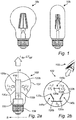
- Incandescent lamps are rapidly being replaced by LED based lighting solutions. It is nevertheless appreciated and desired to have retrofit lamps which have the features (e.g. the look) of an incandescent bulb. For this purpose, it is possible to produce incandescent lamps and replace the filaments with LEDs emitting white light. The appearance of the lamps of this kind, of which lamps 10a,b are presented as examples in Fig. 1 , is highly appreciated. However, it should be noted that the current LED filament lamps are not color controllable. LED filaments emitting different color temperatures may be used, but it is usually not appreciated or desired to see LED filaments emitting different color temperatures. Hence, alternative solutions are of interest, such that a color controllable lighting arrangement may be provided while the lighting arrangement still possesses desired, aesthetic properties during operation.
- Fig. 2a shows a light emitting diode, LED, filament lamp 100 according to an exemplifying embodiment of the present invention.
- the LED filament lamp 100 is exemplified as a bulb-shaped lamp extending along a longitudinal axis A of the LED filament lamp 100.
- the LED filament lamp 100 further comprises an envelope 102, which preferably is made of glass.
- the LED filament lamp 100 further comprises a threaded cap 104 which is connected to the envelope 102.
- the LED filament lamp 100 further comprises a LED light source 110.
- the LED light source 110 in its turn, comprises a first filament 120a extending along the longitudinal axis A.
- the first filament 120a comprises a substrate 130a of elongated shape, upon which a plurality of LEDs (not shown) are arranged.
- the first filament 120a is arranged to emit light having a first intensity L 1 and first color temperature CT 1 .
- the first color temperature CT 1 may, for example, be in the range of 2000 K to 2600 K.
- the LED light source 110 of the LED filament lamp 100 further comprises a second filament 120b extending parallel to the first filament 120a and along the longitudinal axis A.
- the second filament 120b comprises a substrate 130b of elongated shape upon which a plurality of LEDs (not shown) are arranged.
- the second filament 120b is arranged to emit light having a second intensity L 2 and a second color temperature CT 2 during operation of the LED filament lamp 100.
- the second color temperature CT 2 is different from the first color temperature CT 1 .
- the second color temperature CT 2 may, for example, be in the range of 2700 K to 3500 K.
- the first and second filaments 120a, 120b of the LED light source 110 are separated by an average distance D 1 along an axis B perpendicular to the longitudinal axis A.
- the average distance D 1 between the first and second filaments 120a, 120b may be 2 mm to 20 mm, preferably 3 mm to 17 mm, and most preferred 4 to 15 mm.
- the average distance D 1 may hereby be large enough such that the first and second filaments 120a, 120b may be individually visible by a person at a relatively low intensity or an off-state of the LED light source 110.
- the average distance D 1 may at the same time be small enough such that the first and second filaments 120a, 120b are not individually distinguishable at a relatively high intensity setting of the LED light source 110.
- the angle between the first and second filaments 120a, 120b of the LED light source 110 with respect to the longitudinal axis A is preferably less than 30°, more preferably less than 20°, even more preferred less than 10°, such as for example 0°.
- the mutual angle between the first and second filaments 120a, 120b may be in the range of 0-60°, preferably 0-45°, and even more preferred 10-30°.
- the LED filament lamp 100 further comprises a control unit 150.
- the control unit 150 is exemplified as an element being arranged between the first and second filaments 120a, 120b and the cap 104, but it should be noted that he arrangement, size, structure etc., of the control unit 150 may be different than that shown.
- the control unit 150 is configured to control the first intensity L 1 of the light emitted from the first filament(s) 120a and to control the second intensity L 2 of the light emitted from the second filament(s) 120b according to at least one predetermined setting. Consequently, the control unit 150 may control the total color temperature CT tot of the light emitted from the LED filament lamp 100 as a function of the at least one predetermined setting. It should be noted that examples of the operation of the control unit 150 according to predetermined settings are presented in Figs. 4-7 .
- Fig. 2b shows a top view of the LED filament lamp 100 according to Fig. 2a , i.e. along the longitudinal axis A of the LED filament lamp 100.
- the LED light source comprises three pairs 145a-c of first and second filaments 120a, 120b. Analogously with the embodiment of Fig.
- the first filaments 120a of each of the pairs 145a-c is arranged to emit light having a first intensity L 1 and a first color temperature CT 1
- the second filaments 120b of each of the pairs 145a-c are arranged to emit light having a second intensity L 2 and a second color temperature CT 2 (for reasons of simplicity, the emitted intensities and color temperatures are only indicated for the pair 145b of first and second filaments 120a, 120b).
- the pairs 145a-c are arranged along the sides of an (imaginary) equilateral triangle.
- the LED light source may comprise substantially any number of first and second filaments 120a, 120b, it is preferred to use at least three filaments, more preferably at least four filaments, and even more preferred at least five filaments.
- the number of filaments is preferably even, for example six, eight or twelve. It should be noted that in case the LED light source comprises more than two filaments, the person (stylistically indicated by an eye 155) may not be able to see that the filaments emit light of different color temperature.
- the distance D 2 between the two outermost LED filaments may preferably be 50 mm or less, more preferably ⁇ 40 mm, and most preferred ⁇ 35 mm.
- the number of first and second LED filaments need not to be equal.
- the ratio between the number of first LED filaments and second filaments may be in the range from 0.5 to 2.
- the number of first LED filaments may be higher than the number of second LED filaments.
- Fig. 3a shows an example of first and second filaments 120a, 120b of a LED light source 110 comprised in a LED filament lamp according to an exemplifying embodiment of the present invention.
- the first and second filaments 120a, 120b differ from each other in that the LEDs 140a arranged on the substrate 130a of the first filament 120a are of a different type than the LEDs 140b arranged on the substrate 130b of the second filament 120b.
- the light emitted from the first filament 120a differs from the light emitted from the second filament 120b during operation of the LED filament lamp, whereas at the off-state of the LED filament lamp, the first and second filaments 120a, 120b appear to have similar, or virtually the same, physical appearances.
- Fig. 3b shows an example of first and second filaments 120a, 120b of LED light source 110 comprised in a LED filament lamp according to an exemplifying embodiment of the present invention.
- the first and second filaments 120a, 120b differ in their respective phosphor concentration and/or thickness.
- the phosphor concentration 135b of the second filament 120b is larger than the phosphor concentration 135a of the first filament 120a.
- the first and second filaments 120a, 120b appear to have similar, or virtually the same, physical appearances at the off-state of the LED filament lamp, whereas the light emitted from the first filament 120a differs from the light emitted from the second filament 120b during operation of the LED filament lamp.
- the LEDs 140a, 140b are typically embedded in a coating on the respective substrate 130a, 130b.
- the coatings might comprise a phosphor, and the coating of the substrate 130a might vary in thickness compared to the coating of the substrate 130b.
- Figs. 4-7 show examples of predetermined settings of a control unit of a LED filament lamp according to exemplifying embodiments of the present invention.
- the control unit may, by one or more of the following predetermined settings, control the intensities of the light emitted from the first and second filaments of the LED light source of the LED filament lamp in order to control the total color temperature of the light emitted from the LED filament lamp.
- the control unit may, by one or more of the following predetermined settings, control the intensities of the light emitted from the first and second filaments of the LED light source of the LED filament lamp in order to control the total color temperature of the light emitted from the LED filament lamp.
- control unit may be configured to control the first intensity L 1 of the light emitted from the first filament of the LED light source between any of a first low level, L 10 , a first medium level, L 11 , and a first high level, L 12 , wherein L 10 ⁇ L 11 ⁇ L 12 .
- control unit may be configured to control the second intensity L 2 of the light emitted from the second filament(s) of the LED light source between any of a second low level, L 20 , a second medium level, L 21 , and a second high level, L 22 , wherein L 20 ⁇ L 21 ⁇ L 22 .
- the first low level L 10 and/or the second low level L 20 may, for example, be zero. In other words, the first filament(s) and/or the second filament(s) of the LED light source may be turned off.
- Fig. 4-7 respectively describes an increase in the total color temperature by an increase of the total intensity L tot of the light emitted from the LED light source of the LED filament lamp.
- the reverse operation is feasible, i.e. a decrease in the total color temperature by a decrease of the total intensity of the light emitted from the LED light source of the LED filament lamp (i.e. dimming).
- Figs. 4-7 only the predetermined settings of an increasing total intensity are shown in Figs. 4-7 .
- Fig. 4a shows an embodiment of a predetermined setting, in which the control unit is configured to increase the first intensity L 1 of the light emitted from the first filament(s) from the first low level L 10 to the first high level L 12 , i.e. along the y axis of the first intensity L 1 . Subsequently, the control unit is configured to simultaneously increase the second intensity L 2 of the at least one second filament from the second low level L 20 to the second high level L 22 and decrease the first intensity of the at least one first filament from the first high level L 12 to the first low level L 10 . Consequently, the control unit is configured to control the total color temperature CT tot of the light emitted from the LED filament lamp as a function of this predetermined setting.
- Fig. 4b shows the effect of the operation of the control unit according to Fig. 4a , in terms of total intensity L tot and total color temperature CT tot of the light emitted from the LED filament lamp.
- the total intensity L tot of the light emitted from the LED filament lamp increases from a low level of the total intensity L tot to a high level of the total intensity L tot , whereas the total color temperature CT tot of the light emitted from the LED filament lamp remains substantially constant at a low level.
- the total color temperature CT tot of the light emitted from the LED filament lamp increases from the low level to a high level, whereas the total intensity L tot of the light emitted from the LED filament lamp remains substantially constant at a high level.
- Fig. 5a shows another embodiment of a predetermined setting, in which the control unit is configured to increase the first intensity L 1 of the light emitted from the at least one first filament from the first low level L 10 to the first medium level L 11 , while maintaining the second intensity L 2 of the light emitted from the at least one second filament at the low level L 20 . Subsequently, the control unit may be configured to simultaneously increase the first intensity L 1 of the light emitted from the at least one first filament from the first medium level L 11 to the first high level L 12 , and increase the second intensity L 2 of the light emitted from the at least one second filament from the second low level L 20 to the second high level L 22 .
- Fig. 5b shows the effect of the operation of the control unit according to Fig. 5a , in terms of total intensity L tot and total color temperature CT tot of the light emitted from the LED filament lamp.
- the total intensity L tot of the light emitted from the LED filament lamp increases from a low level to a medium level, whereas the total color temperature CT tot of the light emitted from the LED filament lamp remains substantially constant at a low level.
- the total color temperature CT tot of the light emitted from the LED filament lamp increases from the low level to a high level of the total color temperature CT tot .
- the total color temperature CT tot increases from the low level to a high level of the total color temperature CT tot .
- Fig. 6a shows yet another embodiment of a predetermined setting, in which the control unit is configured to increase the first intensity L 1 of the light emitted from the at least one first filament from the first low level L 10 to a level in a range between the first medium level L 11 and the first high level L 12 , while maintaining the second intensity L 2 of the light emitted from the at least one second filament at the low level L 20 . Subsequently, the control unit is configured to increase the second intensity L 2 of the light emitted from the at least one second filament from the second low level L 20 to a level in a range between the second medium level, L 21 , to the second high level L 22 while maintaining the first intensity L 1 at the medium level L 11 .
- Fig. 6b shows the effect of the operation of the control unit according to Fig. 6a , in terms of total intensity L tot and total color temperature CT tot of the light emitted from the LED filament lamp.
- the total color temperature CT tot of the light emitted from the LED filament lamp increases gradually from the low level of the total color temperature C tot , and at a somewhat higher rate compared to the predetermined setting as exemplified in Fig. 5a .
- Fig. 7a shows yet another embodiment of a predetermined setting, in which the control unit may further be configured to increase the first intensity L 1 of the light emitted from the at least one first filament from the first low level L 10 to a level in the range between the first medium level L 11 and the first high level L 12 , while maintaining the second intensity L 2 of the light emitted from the at least one second filament at the low level L 20 . Subsequently, the control unit may simultaneously maintain the first intensity L 1 of the light emitted from the at least one first filament at the level in the range between the first medium level L 11 and the first high level L 12 , and increase the second intensity L 2 of the light emitted from the at least one second filament from the second low level L 20 to the second medium level L 21 .
- control unit may simultaneously decrease the first intensity L 1 of the light emitted from the at least one first filament from the level in the range between the first medium level L 11 and the first high level L 12 to the first low level L 10 , and increase the second intensity L 2 of the light emitted from the at least one second filament from the second medium level L 21 to a level in the range between the second medium level L 21 and the second high level L 22 .
- Fig. 7b shows the effect of the operation of the control unit according to Fig. 7a , in terms of total intensity L tot and total color temperature CT tot of the light emitted from the LED filament lamp.
- the total color temperature CT tot of the light emitted from the LED filament lamp increases gradually from the low level to the medium level of the total color temperature CT tot .
- the total color temperature CT tot of the light emitted from the LED filament lamp increases sharply.
- first and/or second filaments 120a, 120b, the control unit 150, the envelope 102, etc. may have different shapes, dimensions and/or sizes than those depicted/described.
- control unit 150 may be configured to control the first and/or second intensities of the light emitted from first and/or second filaments, respectively, according to substantially any predetermined setting, of which Figs. 4-7 merely show examples.
Claims (14)
- Leuchtdioden-, LED-, Filamentlampe (100), umfassendmindestens eine Leuchtdioden-Lichtquelle (110), umfassendmindestens ein erstes Filament (120a), das so eingerichtet ist, dass es Licht mit einer ersten Farbtemperatur, CT1, emittiert,mindestens ein zweites Filament (120b), das so eingerichtet ist, dass es Licht mit einer zweiten Farbtemperatur, CT2, emittiert, die sich von der ersten Farbtemperatur unterscheidet,wobei jedes von dem mindestens einen ersten Filament und dem mindestens einen zweiten Filament ein Substrat (130a, 130b) mit länglicher Form umfasst, wobei mindestens eine Licht emittierende Diode (140a, 140b) auf dem Substrat eingerichtet ist,eine Steuereinheit (150), die konfiguriert ist, um eine erste Intensität, L1, des von dem mindestens einen ersten Filament emittierten Lichtszu steuern und um eine zweite Intensität, L2, zu steuern, des von dem mindestens einen zweiten Filament emittierten Lichts gemäß mindestens einer vorbestimmten Einstellung zu steuern, um die Gesamtfarbtemperatur, CTtot, des von der LED-Filamentlampe emittierten Lichts in Abhängigkeit von der mindestens einen vorbestimmten Einstellung zu steuern, dadurch gekennzeichnet, dassdie Steuereinheit konfiguriert ist, um ein Umschalten des mindestens einen zweiten Filaments in Abhängigkeit von der Intensität des von dem mindestens einen ersten Filament emittierten Lichts zu steuern, d.h. die Steuereinheit erhöht die erste Intensität L1 bis zu einem vorbestimmten Schwellenwert und schaltet anschließend das mindestens eine zweite Filament um und erhöht die zweite Intensität L2, wobei der Schwellenwert zwischen einer Intensität von 30 % und 70 % seiner maximalen Intensität liegt und die Steuereinheit konfiguriert ist, um die zweite Intensität L2 des von dem mindestens einen zweiten Filament emittierten Lichts zu verringern und das mindestens eine zweite Filament auszuschalten, wenn die erste Intensität L1 des von dem mindestens einen ersten Filament emittierten Lichts bei oder über einem vorbestimmten Schwellenwert liegt.
- LED-Filamentlampe nach Anspruch 1, wobei der Schwellenwert vorzugsweise zwischen 40 % und 65 % und besonders bevorzugt zwischen 55 % und 60 % der maximalen Intensität liegt.
- LED-Filamentlampe nach einem der vorstehenden Ansprüche, wobei die Steuereinheit konfiguriert ist zumSteuern der ersten Intensität, L1, des von dem mindestens einen ersten Filament emittierten Lichts zwischen einem ersten niedrigen Pegel, L10, einem ersten mittleren Pegel, L11, und einem ersten hohen Pegel, L12, wobei L10 < L11 < L12, und zumSteuern der zweiten Intensität, L2, des von dem mindestens einen zweiten Filament emittierten Lichts zwischen einem zweiten niedrigen Pegel, L20, einem zweiten mittleren Pegel, L21, und einem zweiten hohen Pegel, L22, wobei L20 < L21 < L22.
- LED-Filamentlampe nach Anspruch 3, wobei die Steuereinheit konfiguriert ist zumErhöhen der ersten Intensität, L1, des von dem mindestens einen ersten Filament emittierten Lichts von dem ersten niedrigen Pegel, L10, auf den ersten hohen Pegel, L12, und anschließend,gleichzeitigem Erhöhen der zweiten Intensität, L2, des von dem mindestens einen zweiten Filament emittierten Lichts von dem zweiten niedrigen Pegel, L20, auf den zweiten hohen Pegel, L22, und Verringern der ersten Intensität, L1, des von dem mindestens einen ersten Filament emittierten Lichts von dem ersten hohen Pegel, L12, auf den ersten niedrigen Pegel, L10.
- LED-Filamentlampe nach Anspruch 3 oder 4, wobei die Steuereinheit konfiguriert ist zumgleichzeitigem Verringern der zweiten Intensität, L2, des von dem mindestens einen zweiten Filament emittierten Lichts von dem zweiten hohen Pegel, L22, auf den zweiten niedrigen Pegel, L20, und Erhöhen der ersten Intensität, L1, des von dem mindestens einen ersten Filament emittierten Lichts von dem ersten niedrigen Pegel, L10, auf den ersten hohen Pegel, L12, und anschließendVerringern der ersten Intensität, L1, des von dem mindestens einen ersten Filament emittierten Lichts von dem ersten hohen Pegel, L12, auf den ersten niedrigen Pegel, L10.
- LED-Filamentlampe nach Anspruch 3, wobei die Steuereinheit weiter konfiguriert ist zumErhöhen der ersten Intensität, L1, des von dem mindestens einen ersten Filament emittierten Lichts von dem ersten niedrigen Pegel, L10 auf den ersten mittleren Pegel, L11, und anschließend,gleichzeitigem Erhöhen der ersten Intensität, L1, des von dem mindestens einen ersten Filament emittierten Lichts von dem ersten mittleren Pegel, L11, auf den ersten hohen Pegel, L12, und Erhöhen der zweiten Intensität, L2, des von dem mindestens einen zweiten Filament emittierten Lichts von dem zweiten niedrigen Pegel, L20, auf den zweiten hohen Pegel, L10.
- LED-Filamentlampe nach Anspruch 3 oder 6, wobei die Steuereinheit weiter konfiguriert ist zumgleichzeitigem Verringern der ersten Intensität, L1, des von dem mindestens einen ersten Filament emittierten Lichts von dem ersten hohen Pegel, L12, auf den ersten mittleren Pegel, L11, und Verringern der zweiten Intensität, L2, des von dem mindestens einen zweiten Filament emittierten Lichts von dem zweiten hohen Pegel, L22, auf den zweiten niedrigen Pegel, L20, und anschließend,Verringern der ersten Intensität, L1, des von dem mindestens einen ersten Filament emittierten Lichts von dem ersten mittleren Pegel, L11, auf den ersten niedrigen Pegel, L10.
- LED-Filamentlampe nach Anspruch 3, wobei die Steuereinheit weiter konfiguriert ist zumErhöhen der ersten Intensität, L1, des von dem mindestens einen ersten Filament emittierten Lichts von dem ersten niedrigen Pegel, L10, auf einen Pegel in einem Bereich zwischen dem ersten mittleren Pegel, L11, und dem ersten hohen Pegel, L12, und anschließend,Erhöhen der zweiten Intensität, L2, des von dem mindestens einen zweiten Filament emittierten Lichts von dem zweiten niedrigen Pegel, L20, auf einen Pegel in einem Bereich zwischen dem zweiten mittleren Pegel, L21, und dem zweiten hohen Pegel, L22.
- LED-Filamentlampe nach Anspruch 3 oder 8, wobei die Steuereinheit weiter konfiguriert ist zumVerringern der zweiten Intensität, L2, des von dem mindestens einen zweiten Filament emittierten Lichts von einem Pegel in einem Bereich zwischen dem zweiten mittleren Pegel, L21, und dem zweiten hohen Pegel, L22, auf den zweiten niedrigen Pegel, L20, und anschließend,Verringern der ersten Intensität, L1, des von dem mindestens einen ersten Filament emittierten Lichts von einem Pegel in einem Bereich zwischen dem ersten mittleren Pegel, L11, und dem ersten hohen Pegel, L12, auf den ersten niedrigen Pegel L10.
- LED-Filamentlampe nach Anspruch 3, wobei die Steuereinheit weiter konfiguriert ist zumErhöhen der ersten Intensität, L1, des von dem mindestens einen ersten Filament emittierten Lichts von dem ersten niedrigen Pegel, L10, auf einen Pegel in einem Bereich zwischen dem ersten mittleren Pegel, L11, und dem ersten hohen Pegel, L12, und anschließend,gleichzeitigem Beibehalten der ersten Intensität, L1, des von dem mindestens einen ersten Filament emittierten Lichts auf dem Pegel im Bereich zwischen dem ersten mittleren Pegel, L11, und dem ersten hohen Pegel, L12, und Erhöhen der zweiten Intensität, L2, des von dem mindestens einen zweiten Filament emittierten Lichts von dem zweiten niedrigen Pegel, L20, auf den zweiten mittleren Pegel, L21, und anschließendgleichzeitigem Verringern der ersten Intensität, L1, des von dem mindestens einen ersten Filament emittierten Lichts von dem Pegel im Bereich zwischen dem ersten mittleren Pegel, L11, und dem ersten hohen Pegel, L12, auf den ersten niedrigen Pegel, L10, und Erhöhen der zweiten Intensität, L2, des von dem mindestens einen zweiten Filament emittierten Lichts von dem zweiten mittleren Pegel, L21, auf einen Pegel in einem Bereich zwischen dem zweiten mittleren Pegel, L21, und dem zweiten hohen Pegel, L22.
- LED-Filamentlampe nach Anspruch 3 oder 8, wobei die Steuereinheit weiter konfiguriert ist zumgleichzeitigem Erhöhen der ersten Intensität, L1, des von dem mindestens einen ersten Filament emittierten Lichts von dem ersten niedrigen Pegel, L10, auf einen Pegel in einem Bereich zwischen dem ersten mittleren Pegel, L11, und dem ersten hohen Pegel, L12, und Verringern der zweiten Intensität, L2, des von dem mindestens einen zweiten Filament emittierten Lichts von einem Pegel in einem Bereich zwischen dem zweiten mittleren Pegel, L21, und dem zweiten hohen Pegel, L22, auf den zweiten mittleren Pegel, L21, und anschließend,gleichzeitigem Beibehalten der ersten Intensität, L1, des von dem mindestens einen ersten Filament emittierten Lichts auf dem Pegel im Bereich zwischen dem ersten mittleren Pegel, L11 und dem ersten hohen Pegel, L12, und Verringern der zweiten Intensität, L2, des von dem mindestens einen zweiten Filament emittierten Lichts von dem zweiten mittlerenm Pegel, L21, auf den zweiten niedrigen Pegel, L20, und anschließendVerringern der ersten Intensität, L1, des von dem mindestens einen ersten Filament emittierten Lichts von dem Pegel im Bereich zwischen dem ersten mittleren Pegel, L11, und dem ersten hohen Pegel, L12, auf den ersten niedrigen Pegel, L10.
- LED-Filamentlampe nach einem der vorstehenden Ansprüche, wobei der erste Bereich der Farbtemperatur des Lichts des mindestens einen ersten Filaments 2000 K bis 2600 K beträgt, und der zweite Bereich der Farbtemperatur des Lichts des mindestens einen zweiten Filaments 2700 K bis 3500 K beträgt.
- LED-Filamentlampe nach einem der vorstehenden Ansprüche, wobei mindestens eines der mindestens einen ersten Filamente und mindestens eines der mindestens einen zweiten Filamente als mindestens ein Paar von angrenzend eingerichteten Filamenten eingerichtet sind, die sich entlang einer Längsachse, A, der LED-Filamentlampe erstrecken, wobei die Filamente des Paares entlang einer Achse, B, die senkrecht zur Längsachse verläuft, um einen mittleren Abstand, D1, getrennt sind.
- LED-Filamentlampe nach einem der vorstehenden Ansprüche, wobei sich mindestens eine Phosphorkonzentration, eine Dicke und der Typ der mindestens einen lichtemittierenden Diode des mindestens einen ersten Filaments von der jeweiligen Phosphorkonzentration, Dicke und dem Typ der mindestens einen lichtemittierenden Diode des mindestens einen zweiten Filaments unterscheidet.
Applications Claiming Priority (2)
| Application Number | Priority Date | Filing Date | Title |
|---|---|---|---|
| EP18158870 | 2018-02-27 | ||
| PCT/EP2019/054046 WO2019166273A1 (en) | 2018-02-27 | 2019-02-19 | Led filament lamp comprising a control unit |
Publications (2)
| Publication Number | Publication Date |
|---|---|
| EP3760001A1 EP3760001A1 (de) | 2021-01-06 |
| EP3760001B1 true EP3760001B1 (de) | 2021-10-06 |
Family
ID=61521336
Family Applications (1)
| Application Number | Title | Priority Date | Filing Date |
|---|---|---|---|
| EP19705184.0A Active EP3760001B1 (de) | 2018-02-27 | 2019-02-19 | Led-filament mit einer steuereinheit |
Country Status (5)
| Country | Link |
|---|---|
| US (1) | US11293597B2 (de) |
| EP (1) | EP3760001B1 (de) |
| JP (1) | JP7377823B2 (de) |
| CN (1) | CN112042277B (de) |
| WO (1) | WO2019166273A1 (de) |
Families Citing this family (7)
| Publication number | Priority date | Publication date | Assignee | Title |
|---|---|---|---|---|
| CN114502876A (zh) * | 2019-10-01 | 2022-05-13 | 昕诺飞控股有限公司 | Led灯丝装置 |
| US20220390074A1 (en) * | 2019-11-15 | 2022-12-08 | Signify Holding B.V. | Led filament and led filament lamp |
| US20230015999A1 (en) * | 2020-01-02 | 2023-01-19 | Signify Holding B.V. | Lighting device |
| JP2023509163A (ja) * | 2020-01-02 | 2023-03-07 | シグニファイ ホールディング ビー ヴィ | Ledフィラメント構成 |
| WO2021209382A1 (en) | 2020-04-16 | 2021-10-21 | Signify Holding B.V. | Color temperature controllable led filament lamp providing improved light quality |
| JP7362948B2 (ja) | 2020-05-07 | 2023-10-17 | シグニファイ ホールディング ビー ヴィ | Ledフィラメント及びランプ |
| EP4275230A1 (de) * | 2021-01-06 | 2023-11-15 | Signify Holding B.V. | Filamentbasierte festkörperbeleuchtungsvorrichtung |
Family Cites Families (20)
| Publication number | Priority date | Publication date | Assignee | Title |
|---|---|---|---|---|
| EP3722665B1 (de) * | 2004-09-29 | 2022-01-05 | Signify Holding B.V. | Beleuchtungsvorrichtung |
| GB2421367B (en) * | 2004-12-20 | 2008-09-03 | Stephen Bryce Hayes | Lighting apparatus and method |
| US10240724B2 (en) * | 2015-08-17 | 2019-03-26 | Zhejiang Super Lighting Electric Appliance Co., Ltd. | LED filament |
| US9228702B2 (en) * | 2009-03-23 | 2016-01-05 | Eldolab Holding B.V. | LED lamp comprising light guide including first and second diffusing surfaces |
| EP3653924B1 (de) * | 2010-12-22 | 2024-04-17 | Signify Holding B.V. | Beleuchtungsvorrichtung |
| JP2012146738A (ja) | 2011-01-07 | 2012-08-02 | Stanley Electric Co Ltd | Ledモジュール及びledランプ |
| US9408278B2 (en) | 2012-02-07 | 2016-08-02 | Panasonic Intellectual Property Management Co., Ltd. | Light-emitting circuit with variable resistor element, and light-emitting module and illumination device including the same |
| US20140268779A1 (en) | 2013-03-15 | 2014-09-18 | Litetronics International, Inc. | Led light emitting device |
| US20140355292A1 (en) * | 2013-05-30 | 2014-12-04 | Gabriel Krause | Fiber Optic Filament Lamp |
| CN106465510B (zh) * | 2014-03-20 | 2019-10-01 | 东芝高新材料公司 | 发光装置以及led灯泡 |
| WO2016088412A1 (ja) | 2014-12-05 | 2016-06-09 | シャープ株式会社 | 発光装置および照明器具 |
| JP2016129126A (ja) | 2015-01-09 | 2016-07-14 | パナソニックIpマネジメント株式会社 | 照明システムおよび照明器具 |
| WO2016145450A1 (en) | 2015-03-12 | 2016-09-15 | GE Lighting Solutions, LLC | Led lamp with encapsulated driver and safety circuit |
| US9420644B1 (en) * | 2015-03-31 | 2016-08-16 | Frank Shum | LED lighting |
| CN205208156U (zh) | 2015-10-30 | 2016-05-04 | 皇家飞利浦有限公司 | Led灯 |
| JP6558698B2 (ja) * | 2015-12-10 | 2019-08-14 | パナソニックIpマネジメント株式会社 | 発光装置、照明器具及び発光装置の調整方法 |
| GB2546977A (en) * | 2016-01-29 | 2017-08-09 | Global Design Solutions Ltd | A lamp unit |
| CN205746175U (zh) | 2016-06-28 | 2016-11-30 | 横店集团得邦照明股份有限公司 | 一种可调光调色的led灯 |
| CN206176271U (zh) * | 2016-11-08 | 2017-05-17 | 横店集团得邦照明股份有限公司 | 一种可调光调色的led灯丝灯 |
| CN207049647U (zh) * | 2017-08-23 | 2018-02-27 | 福建鸿博光电科技有限公司 | 一种可调色温的led灯具 |
-
2019
- 2019-02-19 US US16/975,371 patent/US11293597B2/en active Active
- 2019-02-19 JP JP2020568029A patent/JP7377823B2/ja active Active
- 2019-02-19 CN CN201980028529.5A patent/CN112042277B/zh active Active
- 2019-02-19 EP EP19705184.0A patent/EP3760001B1/de active Active
- 2019-02-19 WO PCT/EP2019/054046 patent/WO2019166273A1/en unknown
Also Published As
| Publication number | Publication date |
|---|---|
| JP7377823B2 (ja) | 2023-11-10 |
| US11293597B2 (en) | 2022-04-05 |
| US20210033247A1 (en) | 2021-02-04 |
| JP2021515418A (ja) | 2021-06-17 |
| WO2019166273A1 (en) | 2019-09-06 |
| EP3760001A1 (de) | 2021-01-06 |
| CN112042277B (zh) | 2023-05-02 |
| CN112042277A (zh) | 2020-12-04 |
Similar Documents
| Publication | Publication Date | Title |
|---|---|---|
| EP3760001B1 (de) | Led-filament mit einer steuereinheit | |
| US7476004B2 (en) | LED lighting lamp tube | |
| US9228702B2 (en) | LED lamp comprising light guide including first and second diffusing surfaces | |
| WO2009150574A1 (en) | Lamp unit and luminaire | |
| US20140268750A1 (en) | Lighting fixture with reflector and template pcb | |
| JP2011014515A (ja) | 照度並びに配光性に優れる照明具 | |
| KR101056515B1 (ko) | 하이브리드 조명 장치 | |
| KR20110023231A (ko) | 봉형 엘이디조명등기구 | |
| EP4004432B1 (de) | Led-filament-anordnung | |
| US20230091712A1 (en) | Dimmable helix led filament arrangement and lamp | |
| KR20090060490A (ko) | 발광 다이오드를 채용한 조명 기구 | |
| US20120044676A1 (en) | Structure of light-emitting diode (LED) lamp | |
| WO2012107863A1 (en) | Method for color mixing | |
| CN113330245A (zh) | Led灯丝装置 | |
| US11933487B2 (en) | Lighting device | |
| CN102720964A (zh) | 一种改进的led灯 | |
| KR20190048802A (ko) | 다색 발광 조명 장치 | |
| KR20100066683A (ko) | Led 조명장치 | |
| WO2023232670A1 (en) | Led filament comprising leds arranged to emit uv light | |
| WO2024028211A1 (en) | Lamp having different uv led filaments emitting different uv light asymmetrically arranged in said lamp | |
| TW201546395A (zh) | 中央光源式光纖照明系統 | |
| WO2023131551A1 (en) | Led filament for illumination and disinfection | |
| WO2007058561A1 (fr) | Appareil d'eclairage | |
| WO2013028972A1 (en) | Led brilliant illumination light pipe lighting | |
| JP2022519952A (ja) | 固体ランプ |
Legal Events
| Date | Code | Title | Description |
|---|---|---|---|
| STAA | Information on the status of an ep patent application or granted ep patent |
Free format text: STATUS: UNKNOWN |
|
| STAA | Information on the status of an ep patent application or granted ep patent |
Free format text: STATUS: THE INTERNATIONAL PUBLICATION HAS BEEN MADE |
|
| PUAI | Public reference made under article 153(3) epc to a published international application that has entered the european phase |
Free format text: ORIGINAL CODE: 0009012 |
|
| STAA | Information on the status of an ep patent application or granted ep patent |
Free format text: STATUS: REQUEST FOR EXAMINATION WAS MADE |
|
| 17P | Request for examination filed |
Effective date: 20200928 |
|
| AK | Designated contracting states |
Kind code of ref document: A1 Designated state(s): AL AT BE BG CH CY CZ DE DK EE ES FI FR GB GR HR HU IE IS IT LI LT LU LV MC MK MT NL NO PL PT RO RS SE SI SK SM TR |
|
| AX | Request for extension of the european patent |
Extension state: BA ME |
|
| GRAP | Despatch of communication of intention to grant a patent |
Free format text: ORIGINAL CODE: EPIDOSNIGR1 |
|
| STAA | Information on the status of an ep patent application or granted ep patent |
Free format text: STATUS: GRANT OF PATENT IS INTENDED |
|
| DAV | Request for validation of the european patent (deleted) | ||
| DAX | Request for extension of the european patent (deleted) | ||
| INTG | Intention to grant announced |
Effective date: 20210507 |
|
| GRAS | Grant fee paid |
Free format text: ORIGINAL CODE: EPIDOSNIGR3 |
|
| GRAA | (expected) grant |
Free format text: ORIGINAL CODE: 0009210 |
|
| STAA | Information on the status of an ep patent application or granted ep patent |
Free format text: STATUS: THE PATENT HAS BEEN GRANTED |
|
| AK | Designated contracting states |
Kind code of ref document: B1 Designated state(s): AL AT BE BG CH CY CZ DE DK EE ES FI FR GB GR HR HU IE IS IT LI LT LU LV MC MK MT NL NO PL PT RO RS SE SI SK SM TR |
|
| REG | Reference to a national code |
Ref country code: GB Ref legal event code: FG4D |
|
| REG | Reference to a national code |
Ref country code: CH Ref legal event code: EP Ref country code: AT Ref legal event code: REF Ref document number: 1437413 Country of ref document: AT Kind code of ref document: T Effective date: 20211015 |
|
| REG | Reference to a national code |
Ref country code: IE Ref legal event code: FG4D |
|
| REG | Reference to a national code |
Ref country code: DE Ref legal event code: R096 Ref document number: 602019008189 Country of ref document: DE |
|
| REG | Reference to a national code |
Ref country code: DE Ref legal event code: R079 Ref document number: 602019008189 Country of ref document: DE Free format text: PREVIOUS MAIN CLASS: H05B0033080000 Ipc: H05B0044000000 |
|
| REG | Reference to a national code |
Ref country code: LT Ref legal event code: MG9D |
|
| REG | Reference to a national code |
Ref country code: NL Ref legal event code: MP Effective date: 20211006 |
|
| REG | Reference to a national code |
Ref country code: AT Ref legal event code: MK05 Ref document number: 1437413 Country of ref document: AT Kind code of ref document: T Effective date: 20211006 |
|
| PG25 | Lapsed in a contracting state [announced via postgrant information from national office to epo] |
Ref country code: RS Free format text: LAPSE BECAUSE OF FAILURE TO SUBMIT A TRANSLATION OF THE DESCRIPTION OR TO PAY THE FEE WITHIN THE PRESCRIBED TIME-LIMIT Effective date: 20211006 Ref country code: LT Free format text: LAPSE BECAUSE OF FAILURE TO SUBMIT A TRANSLATION OF THE DESCRIPTION OR TO PAY THE FEE WITHIN THE PRESCRIBED TIME-LIMIT Effective date: 20211006 Ref country code: FI Free format text: LAPSE BECAUSE OF FAILURE TO SUBMIT A TRANSLATION OF THE DESCRIPTION OR TO PAY THE FEE WITHIN THE PRESCRIBED TIME-LIMIT Effective date: 20211006 Ref country code: BG Free format text: LAPSE BECAUSE OF FAILURE TO SUBMIT A TRANSLATION OF THE DESCRIPTION OR TO PAY THE FEE WITHIN THE PRESCRIBED TIME-LIMIT Effective date: 20220106 Ref country code: AT Free format text: LAPSE BECAUSE OF FAILURE TO SUBMIT A TRANSLATION OF THE DESCRIPTION OR TO PAY THE FEE WITHIN THE PRESCRIBED TIME-LIMIT Effective date: 20211006 |
|
| PG25 | Lapsed in a contracting state [announced via postgrant information from national office to epo] |
Ref country code: IS Free format text: LAPSE BECAUSE OF FAILURE TO SUBMIT A TRANSLATION OF THE DESCRIPTION OR TO PAY THE FEE WITHIN THE PRESCRIBED TIME-LIMIT Effective date: 20220206 Ref country code: SE Free format text: LAPSE BECAUSE OF FAILURE TO SUBMIT A TRANSLATION OF THE DESCRIPTION OR TO PAY THE FEE WITHIN THE PRESCRIBED TIME-LIMIT Effective date: 20211006 Ref country code: PT Free format text: LAPSE BECAUSE OF FAILURE TO SUBMIT A TRANSLATION OF THE DESCRIPTION OR TO PAY THE FEE WITHIN THE PRESCRIBED TIME-LIMIT Effective date: 20220207 Ref country code: PL Free format text: LAPSE BECAUSE OF FAILURE TO SUBMIT A TRANSLATION OF THE DESCRIPTION OR TO PAY THE FEE WITHIN THE PRESCRIBED TIME-LIMIT Effective date: 20211006 Ref country code: NO Free format text: LAPSE BECAUSE OF FAILURE TO SUBMIT A TRANSLATION OF THE DESCRIPTION OR TO PAY THE FEE WITHIN THE PRESCRIBED TIME-LIMIT Effective date: 20220106 Ref country code: NL Free format text: LAPSE BECAUSE OF FAILURE TO SUBMIT A TRANSLATION OF THE DESCRIPTION OR TO PAY THE FEE WITHIN THE PRESCRIBED TIME-LIMIT Effective date: 20211006 Ref country code: LV Free format text: LAPSE BECAUSE OF FAILURE TO SUBMIT A TRANSLATION OF THE DESCRIPTION OR TO PAY THE FEE WITHIN THE PRESCRIBED TIME-LIMIT Effective date: 20211006 Ref country code: HR Free format text: LAPSE BECAUSE OF FAILURE TO SUBMIT A TRANSLATION OF THE DESCRIPTION OR TO PAY THE FEE WITHIN THE PRESCRIBED TIME-LIMIT Effective date: 20211006 Ref country code: GR Free format text: LAPSE BECAUSE OF FAILURE TO SUBMIT A TRANSLATION OF THE DESCRIPTION OR TO PAY THE FEE WITHIN THE PRESCRIBED TIME-LIMIT Effective date: 20220107 Ref country code: ES Free format text: LAPSE BECAUSE OF FAILURE TO SUBMIT A TRANSLATION OF THE DESCRIPTION OR TO PAY THE FEE WITHIN THE PRESCRIBED TIME-LIMIT Effective date: 20211006 |
|
| REG | Reference to a national code |
Ref country code: DE Ref legal event code: R097 Ref document number: 602019008189 Country of ref document: DE |
|
| PG25 | Lapsed in a contracting state [announced via postgrant information from national office to epo] |
Ref country code: SM Free format text: LAPSE BECAUSE OF FAILURE TO SUBMIT A TRANSLATION OF THE DESCRIPTION OR TO PAY THE FEE WITHIN THE PRESCRIBED TIME-LIMIT Effective date: 20211006 Ref country code: SK Free format text: LAPSE BECAUSE OF FAILURE TO SUBMIT A TRANSLATION OF THE DESCRIPTION OR TO PAY THE FEE WITHIN THE PRESCRIBED TIME-LIMIT Effective date: 20211006 Ref country code: RO Free format text: LAPSE BECAUSE OF FAILURE TO SUBMIT A TRANSLATION OF THE DESCRIPTION OR TO PAY THE FEE WITHIN THE PRESCRIBED TIME-LIMIT Effective date: 20211006 Ref country code: EE Free format text: LAPSE BECAUSE OF FAILURE TO SUBMIT A TRANSLATION OF THE DESCRIPTION OR TO PAY THE FEE WITHIN THE PRESCRIBED TIME-LIMIT Effective date: 20211006 Ref country code: DK Free format text: LAPSE BECAUSE OF FAILURE TO SUBMIT A TRANSLATION OF THE DESCRIPTION OR TO PAY THE FEE WITHIN THE PRESCRIBED TIME-LIMIT Effective date: 20211006 Ref country code: CZ Free format text: LAPSE BECAUSE OF FAILURE TO SUBMIT A TRANSLATION OF THE DESCRIPTION OR TO PAY THE FEE WITHIN THE PRESCRIBED TIME-LIMIT Effective date: 20211006 |
|
| PLBE | No opposition filed within time limit |
Free format text: ORIGINAL CODE: 0009261 |
|
| STAA | Information on the status of an ep patent application or granted ep patent |
Free format text: STATUS: NO OPPOSITION FILED WITHIN TIME LIMIT |
|
| 26N | No opposition filed |
Effective date: 20220707 |
|
| PG25 | Lapsed in a contracting state [announced via postgrant information from national office to epo] |
Ref country code: MC Free format text: LAPSE BECAUSE OF FAILURE TO SUBMIT A TRANSLATION OF THE DESCRIPTION OR TO PAY THE FEE WITHIN THE PRESCRIBED TIME-LIMIT Effective date: 20211006 |
|
| REG | Reference to a national code |
Ref country code: CH Ref legal event code: PL |
|
| REG | Reference to a national code |
Ref country code: BE Ref legal event code: MM Effective date: 20220228 |
|
| PG25 | Lapsed in a contracting state [announced via postgrant information from national office to epo] |
Ref country code: LU Free format text: LAPSE BECAUSE OF NON-PAYMENT OF DUE FEES Effective date: 20220219 Ref country code: AL Free format text: LAPSE BECAUSE OF FAILURE TO SUBMIT A TRANSLATION OF THE DESCRIPTION OR TO PAY THE FEE WITHIN THE PRESCRIBED TIME-LIMIT Effective date: 20211006 |
|
| PG25 | Lapsed in a contracting state [announced via postgrant information from national office to epo] |
Ref country code: SI Free format text: LAPSE BECAUSE OF FAILURE TO SUBMIT A TRANSLATION OF THE DESCRIPTION OR TO PAY THE FEE WITHIN THE PRESCRIBED TIME-LIMIT Effective date: 20211006 |
|
| PG25 | Lapsed in a contracting state [announced via postgrant information from national office to epo] |
Ref country code: LI Free format text: LAPSE BECAUSE OF NON-PAYMENT OF DUE FEES Effective date: 20220228 Ref country code: IE Free format text: LAPSE BECAUSE OF NON-PAYMENT OF DUE FEES Effective date: 20220219 Ref country code: CH Free format text: LAPSE BECAUSE OF NON-PAYMENT OF DUE FEES Effective date: 20220228 |
|
| PG25 | Lapsed in a contracting state [announced via postgrant information from national office to epo] |
Ref country code: BE Free format text: LAPSE BECAUSE OF NON-PAYMENT OF DUE FEES Effective date: 20220228 |
|
| PGFP | Annual fee paid to national office [announced via postgrant information from national office to epo] |
Ref country code: FR Payment date: 20230223 Year of fee payment: 5 |
|
| PG25 | Lapsed in a contracting state [announced via postgrant information from national office to epo] |
Ref country code: IT Free format text: LAPSE BECAUSE OF FAILURE TO SUBMIT A TRANSLATION OF THE DESCRIPTION OR TO PAY THE FEE WITHIN THE PRESCRIBED TIME-LIMIT Effective date: 20211006 |
|
| PGFP | Annual fee paid to national office [announced via postgrant information from national office to epo] |
Ref country code: GB Payment date: 20230214 Year of fee payment: 5 |
|
| P01 | Opt-out of the competence of the unified patent court (upc) registered |
Effective date: 20230425 |
|
| PGFP | Annual fee paid to national office [announced via postgrant information from national office to epo] |
Ref country code: DE Payment date: 20230427 Year of fee payment: 5 |