EP4004432B1 - Led-filament-anordnung - Google Patents
Led-filament-anordnung Download PDFInfo
- Publication number
- EP4004432B1 EP4004432B1 EP20739398.4A EP20739398A EP4004432B1 EP 4004432 B1 EP4004432 B1 EP 4004432B1 EP 20739398 A EP20739398 A EP 20739398A EP 4004432 B1 EP4004432 B1 EP 4004432B1
- Authority
- EP
- European Patent Office
- Prior art keywords
- leds
- led filament
- subset
- filament arrangement
- current
- Prior art date
- Legal status (The legal status is an assumption and is not a legal conclusion. Google has not performed a legal analysis and makes no representation as to the accuracy of the status listed.)
- Active
Links
- 230000004907 flux Effects 0.000 claims description 28
- 239000008393 encapsulating agent Substances 0.000 claims description 20
- 239000000463 material Substances 0.000 claims description 19
- 239000000758 substrate Substances 0.000 claims description 16
- 238000000149 argon plasma sintering Methods 0.000 claims description 2
- 239000002245 particle Substances 0.000 claims description 2
- 230000000694 effects Effects 0.000 description 6
- OAICVXFJPJFONN-UHFFFAOYSA-N Phosphorus Chemical compound [P] OAICVXFJPJFONN-UHFFFAOYSA-N 0.000 description 4
- 229920000642 polymer Polymers 0.000 description 3
- 230000008878 coupling Effects 0.000 description 2
- 238000010168 coupling process Methods 0.000 description 2
- 238000005859 coupling reaction Methods 0.000 description 2
- 239000011888 foil Substances 0.000 description 2
- 239000011521 glass Substances 0.000 description 2
- 239000002184 metal Substances 0.000 description 2
- 229910052751 metal Inorganic materials 0.000 description 2
- 230000003287 optical effect Effects 0.000 description 2
- 229920001296 polysiloxane Polymers 0.000 description 2
- 239000002096 quantum dot Substances 0.000 description 2
- 239000010453 quartz Substances 0.000 description 2
- 238000004064 recycling Methods 0.000 description 2
- 229910052594 sapphire Inorganic materials 0.000 description 2
- 239000010980 sapphire Substances 0.000 description 2
- VYPSYNLAJGMNEJ-UHFFFAOYSA-N silicon dioxide Inorganic materials O=[Si]=O VYPSYNLAJGMNEJ-UHFFFAOYSA-N 0.000 description 2
- 239000003086 colorant Substances 0.000 description 1
- 230000007812 deficiency Effects 0.000 description 1
- 230000001419 dependent effect Effects 0.000 description 1
- 230000005284 excitation Effects 0.000 description 1
- 238000005286 illumination Methods 0.000 description 1
- 230000004048 modification Effects 0.000 description 1
- 238000012986 modification Methods 0.000 description 1
- 229910052754 neon Inorganic materials 0.000 description 1
- GKAOGPIIYCISHV-UHFFFAOYSA-N neon atom Chemical compound [Ne] GKAOGPIIYCISHV-UHFFFAOYSA-N 0.000 description 1
- 239000002861 polymer material Substances 0.000 description 1
- 238000001228 spectrum Methods 0.000 description 1
- 239000012780 transparent material Substances 0.000 description 1
Images
Classifications
-
- F—MECHANICAL ENGINEERING; LIGHTING; HEATING; WEAPONS; BLASTING
- F21—LIGHTING
- F21K—NON-ELECTRIC LIGHT SOURCES USING LUMINESCENCE; LIGHT SOURCES USING ELECTROCHEMILUMINESCENCE; LIGHT SOURCES USING CHARGES OF COMBUSTIBLE MATERIAL; LIGHT SOURCES USING SEMICONDUCTOR DEVICES AS LIGHT-GENERATING ELEMENTS; LIGHT SOURCES NOT OTHERWISE PROVIDED FOR
- F21K9/00—Light sources using semiconductor devices as light-generating elements, e.g. using light-emitting diodes [LED] or lasers
- F21K9/20—Light sources comprising attachment means
- F21K9/23—Retrofit light sources for lighting devices with a single fitting for each light source, e.g. for substitution of incandescent lamps with bayonet or threaded fittings
- F21K9/232—Retrofit light sources for lighting devices with a single fitting for each light source, e.g. for substitution of incandescent lamps with bayonet or threaded fittings specially adapted for generating an essentially omnidirectional light distribution, e.g. with a glass bulb
-
- F—MECHANICAL ENGINEERING; LIGHTING; HEATING; WEAPONS; BLASTING
- F21—LIGHTING
- F21Y—INDEXING SCHEME ASSOCIATED WITH SUBCLASSES F21K, F21L, F21S and F21V, RELATING TO THE FORM OR THE KIND OF THE LIGHT SOURCES OR OF THE COLOUR OF THE LIGHT EMITTED
- F21Y2115/00—Light-generating elements of semiconductor light sources
- F21Y2115/10—Light-emitting diodes [LED]
Definitions
- the present invention generally relates to lighting arrangements comprising one or more light emitting diodes. More specifically, the present invention is related to a light emitting diode (LED) filament arrangement.
- LED light emitting diode
- LED light emitting diodes
- LED-based lighting solutions There is currently a very large interest in lighting devices and/or arrangements (such as lamps) provided with LEDs, and incandescent lamps are rapidly being replaced by LED-based lighting solutions. It is nevertheless appreciated and desired to have retrofit lighting devices (e.g. lamps) which have the look of an incandescent bulb. For this purpose, it is possible to make use of the infrastructure for producing incandescent lamps based on LED filaments arranged in such a bulb. In particular, LED filament lamps are highly appreciated as they are very decorative.
- a LED filament is providing LED filament light and comprises a plurality of light emitting diodes (LEDs) arranged in a linear array.
- the LED filament has a length L and a width W, wherein L>5W.
- the LED filament may be arranged in a straight configuration or in a non-straight configuration such as for example a curved configuration, a 2D/3D spiral or a helix.
- the LEDs are arranged on an elongated carrier like for instance a substrate, that may be rigid (made from e.g. a polymer, glass, quartz, metal or sapphire) or flexible (e.g. made of a polymer or metal e.g. a film or foil).
- the carrier comprises a first major surface and an opposite second major surface
- the LEDs are arranged on at least one of these surfaces.
- the carrier may be reflective or light transmissive, such as translucent and preferably transparent.
- the LED filament may comprise an encapsulant at least partly covering at least part of the plurality of LEDs.
- the encapsulant may also at least partly cover at least one of the first major or second major surface.
- the encapsulant may be a polymer material which may be flexible such as for example a silicone. Further, the LEDs may be arranged for emitting LED light e.g. of different colors or spectrums.
- the encapsulant may comprise a luminescent material that is configured to at least partly convert LED light into converted light.
- the luminescent material may be a phosphor such as an inorganic phosphor and/or quantum dots or rods.
- the LED filament may comprise multiple sub-filaments.
- a light emitting diode, LED, filament arrangement comprising at least one LED filament comprising an array of a plurality of light emitting diodes, LEDs, arranged on an elongated substrate, wherein the at least one LED filament comprises at least a first subset, S 1 , of at least two LEDs, and at least a second subset, S 2 , of at least two LEDs, wherein the first subset, S 1 , of LEDs is different from the second subset, S 2 , of LEDs, and wherein the LEDs of the first subset, S 1 , are coupled in series and the LEDs of the second subset, S 2 , are coupled in parallel, such that the luminous flux, ⁇ 1 , of the individual LEDs of the at least a first subset, S 1 , differs from the luminous flux, ⁇ 2 , of the individual LEDs of the second subset, S 2 , during operation of the LED filament arrangement.
- a subset of LEDs may comprise more than one group.
- the meaning of LEDs to be coupled in parallel should be interpreted as all the LEDs within one group are in parallel. For instance, in Fig. 2 the subset S 2 has 8 LEDs subdivided into two groups and each group has 4 LEDs in parallel.
- the present invention is based on the idea of providing a LED filament arrangement which is able to provide different luminous flux of the individual (identical) LEDs arranged linearly on the substrate during operation of the LED filament arrangement. This effect is achieved by providing one or more first subset(s) of LEDs coupled in series, and one or more second subset(s) of LEDs coupled in parallel.
- the present invention is hereby advantageous in that the LED filament arrangement may obtain an aesthetically appealing effect by the variance of luminous flux of the LEDs during operation by its innovative concept.
- the present invention is further advantageous in that the LED filament arrangement achieves a vintage appearance, which is highly desirable and eligible. Furthermore, the luminous flux difference of the LEDs along the substrate may provide a resemblance of candle light, which even further contributes to the decorative aspect of the LED filament arrangement.
- the LED filament arrangement of the present invention furthermore comprises relatively few components.
- the relatively low number of components is advantageous in that the LED filament arrangement is relatively inexpensive to fabricate.
- the relatively low number of components of the LED filament arrangement implies an easier recycling, especially compared to devices or arrangements comprising a relatively high number of components which impede an easy disassembling and/or recycling operation.
- the LED filament arrangement according to the present invention comprises at least one LED filament.
- the at least one LED filament in its turn, comprises an array of LEDs arranged on an elongated substrate.
- array it is here meant a linear arrangement, row or chain of LEDs, or the like, arranged on the LED filament(s).
- the LED filament(s) comprise(s) at least a first subset, S 1 , of at least two LEDs, and at least a second subset, S 2 , of at least two LEDs, wherein at least one of the at least one first subset, S 1 , of LEDs is different from at least one of the at least one second subset, S 2 , of LEDs.
- at least some of the LEDs belonging to the first subset(s) of LEDs are different from at least some of the LEDs belonging to the second subset(s) of LEDs.
- the LEDs of the first subset(s), S 1 are coupled in series and the LEDs of the second subset(s), S 2 , are coupled in parallel.
- the luminous flux of the individual LEDs of the first subset(s), S 1 differs from the luminous flux of the individual LEDs of the second subset(s), S 2 , during operation of the LED filament arrangement.
- the LED filament arrangement may further comprise at least a third subset, S 3 , of at least two LEDs, wherein the at third subset, S 3 , of LEDs is different from the first subset, S 1 , of LEDs and the second subset, S 2 , of LEDs, wherein the LEDs of the third subset, S 3 , are coupled in parallel.
- the present embodiment is advantageous in that the LEDs of the third subset(s), S 3 , may provide a luminous flux which is different from the luminous fluxes of the individual LEDs of the first subset(s), S 1 , and the second subset(s), S 2 , of LEDs. Consequently, this embodiment may even further contribute to the aesthetically appealing effect of the LED filament arrangement by the variance of luminous flux of the LEDs during operation of the LED filament arrangement.
- the LED filament arrangement may comprise a single electrical circuit for a supply of current to the plurality of LEDs.
- the present embodiment is advantageous in that the provision of a single electrical circuit achieves a relatively simple yet efficient arrangement in order to achieve the desired, appealing effect of the LED filament arrangement during operation.
- the LED filament arrangement may comprise a plurality of electrical circuits for a supply of current to the plurality of LEDs.
- the present embodiment is advantageous in that the provision of a plurality of electrical circuits in the LED filament arrangement may conveniently provide different currents to different sets of LEDs, in order to provide a variance of luminous flux of the LEDs during operation of the LED filament arrangement.
- the LEDs may be equidistantly arranged on the substrate.
- the LEDs may be arranged on the substrate in a symmetric manner, wherein each LED is arranged at the same distance from adjacently arranged LEDs.
- the LED filament arrangement may further comprise an encapsulant comprising a light-transmissive material, wherein the encapsulant at least partially encloses the plurality of LEDs, wherein the encapsulant comprises a luminescent material and is configured to at least partly convert the light emitted by the plurality of LEDs.
- the encapsulant may further comprise a luminescent material and may be configured to at least partly convert the light emitted by the plurality of LEDs.
- the encapsulant may further comprise light-scattering particles arranged to scatter the light emitted by the plurality of LEDs.
- the plurality of LEDs may have the same color or color temperature.
- color temperature it is here meant the temperature of an ideal black-body radiator that radiates light of a color comparable to that of the LEDs.
- the plurality of LEDs may have the same color point.
- the plurality of LEDs may be white LEDs.
- a lighting device comprising a LED filament arrangement according to any one of the preceding embodiments.
- the lighting device further comprises at least one electrical connection connected to the LED filament arrangement for a supply of current to the plurality of LEDs, and a control unit coupled to the at least one electrical connection, wherein the control unit is configured to control the supply of current to the plurality of LEDs.
- the present embodiment is advantageous in that the control unit may control and/or vary the supply of current to the LEDs such that an even more appealing effect of the LED filament arrangement may be obtained, as a result of the controlled/varied variance of luminous flux of the LEDs via the control unit.
- the control unit may comprise a random current generator configured to supply current which varies randomly, to the plurality of LEDs.
- random current generator it is here meant substantially any generator, unit, or the like, which is configured to generate and supply a current which randomly varies in amplitude with time.
- the present embodiment is advantageous in that the randomly generated current(s) of the random current generator may even further contribute to obtaining a resemblance of candle light by the light emitted from the LEDs. Consequently, this effect may even further contribute to the decorative aspect of the LED filament arrangement.
- the lighting device may comprise at least one LED filament arrangement, wherein the control unit is configured to control the supply of current individually to each electrical circuit of the plurality of electrical circuits.
- the control unit may control and/or vary the supply of current to the LEDs individually in order to vary the luminous flux of the LEDs via the control unit.
- control unit is further configured to supply at least a first current, I 1 , to at least a first electrical circuit of the plurality of electrical circuits, and supply at least a second current, I 2 , to at least a second electrical circuit of the plurality of electrical circuits, wherein I 1 ⁇ I 2 .
- I 1 a first current
- I 2 a second current
- I 1 ⁇ I 2 a second electrical circuit of the plurality of electrical circuits
- a lighting arrangement comprising a lighting device according to any one of the preceding embodiments.
- the lighting device further comprises a cover comprising an at least partially light-transmissive material, wherein the cover at least partially encloses the LED filament arrangement.
- cover it is here meant an enclosing element, such as a cap, cover, envelope, or the like, comprising an at least partial light-transmissive material, e.g. a translucent and/or transparent material.
- the present embodiment is advantageous in that the lighting device according to the invention may be conveniently arranged in substantially any lighting arrangement, such as a LED filament lamp, luminaire, lighting system, or the like.
- the lighting arrangement may further comprise a driver for supplying power (current) to the plurality of LEDs of the LED filament arrangement. Additionally, the lighting device of the lighting arrangement may further comprise a controller for individual control of two or more subsets of LEDs of the LED filament arrangement, such as a first set of LEDs, a second set of LEDs, etc.
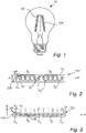
- Fig. 1 shows a LED filament lamp 10 according to the prior art, comprising a LED filament arrangement 100 having a plurality of LED filaments 120.
- LED filament lamps 10 of this kind are highly appreciated as they are very decorative, as well as providing numerous advantages compared to incandescent lamps such as a longer operational life, a reduced power consumption, and an increased efficiency related to the ratio between light energy and heat energy.
- the LED filament arrangement 100 comprises a number of LED filaments 120.
- the LED filament arrangement may preferably comprise 2-10 LED filaments 120, more preferably 3-8 LED filaments 120, and even more preferred 4-6 LED filaments 120.
- said LED filament 120 may preferably have a length L in the range from 1 cm to 20 cm, more preferably 2 cm to 12 cm, and most preferred 3 cm to 10 cm.
- the LED filament 120 comprises an array or "chain” of LEDs 140 extending along an axis A, which is arranged on an elongated substrate 70 of the LED filament arrangement 100.
- the array or "chain” of LEDs 140 may comprise a plurality of adjacently arranged LEDs 140.
- the plurality of LEDs 140 preferably comprises more than 20 LEDs, more preferably more than 25 LEDs, and even more preferred more than 30 LEDs.
- the plurality of LEDs 140 may be direct emitting LEDs which provide a color.
- the LEDs 140 are preferably blue LEDs.
- the LEDs 140 may also be UV LEDs.
- a combination of LEDs 140, e.g. UV LEDs and blue light LEDs, may be used.
- the LEDs 140 may comprise laser diodes.
- the light emitted from the LED filament 120 during operation is preferably white light.
- the white light is preferably within 15 SDCM from the black body locus (BBL).
- the color temperature of the white light is preferably in the range of 2000 to 6000 K, more preferably in the range from 2100 to 5000 K, most preferably in the range from 2200 to 4000 K such as for example 2300 K or 2700 K.
- the white light has preferably a CRI of at least 75, more preferably at least 80, most preferably at least 85 such as for example 90 or 92.
- the substrate 70 of the LED filament arrangement 100 may be flexible, e.g. a foil. Alternatively, the substrate 70 may be rigid, and e.g. be made of glass, quartz, sapphire and/or a polymer.
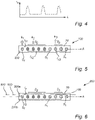
- the LED filament 120 comprises a first subset, S 1 , of three LEDs 140, and a second subset, S 2 , of eight LEDs 140. It should be noted that the number of subsets is arbitrary. Analogously, the number of LEDs 140 of the respective subset is arbitrary.
- the LED filament arrangement 100 comprises a single electrical circuit 200 for a supply of current to the plurality of LEDs 140.
- the LEDs 140 of the first subset, S 1 are coupled in series and the LEDs 140 of the second subset, S 2 , are coupled in parallel.
- the LEDs 140 of the first and second subsets S 1 and S 2 are identical, i.e. they have the same physical, optical and electrical properties.
- the luminous flux of the individual LEDs 140 of the first subset, S 1 differs from the luminous flux of the individual LEDs 140 of the second subset, S 2 , during operation of the LED filament arrangement 100. More specifically, the luminous flux of the individual LEDs 140 of the first subset, S 1 , is higher than the luminous flux of the individual LEDs 140 of the second subset, S 2 .
- Fig. 3 schematically shows the LED filament arrangement 100 of Fig. 2 in a side perspective according to an embodiment of the present invention. Hence, it is also referred to Fig. 2 for component references and associated description for an increased understanding.
- the LED filament arrangement 100 comprises a LED filament 120 which elongates along an axis A. Seen in a direction B, perpendicular to the axis A, the LED filament arrangement 100 comprises a substrate 70 for electrical and/or physical support of a plurality of LEDs 140.
- the LEDs 140 of the first subset, S 1 are coupled in series and the LEDs 140 of the second subset, S 2 , are coupled in parallel.
- the LEDs 140 of the first and second subsets S 1 and S 2 are identical, i.e.
- the luminous flux, ⁇ 1 , of the individual LEDs 140 of the first subset, S 1 differs from the luminous flux, ⁇ 2 , of the individual LEDs 140 of the second subset, S 2 , during operation of the LED filament arrangement 100. More specifically, the luminous flux, ⁇ 1 , of the individual LEDs 140 of the first subset, S 1 , is higher than the luminous flux, ⁇ 2 , of the individual LEDs 140 of the second subset, S 2 , i.e. ⁇ 1 > ⁇ 2 .
- the LED filament arrangement 100 further comprises an encapsulant 145 comprising a light-transmissive material, wherein the encapsulant 145 at least partially encloses the plurality of LEDs 140.
- the elongated encapsulant 145 fully encloses the plurality of LEDs 140, and hence, also at least a portion of the substrate 70.
- the encapsulant 145 may comprise a luminescent material, which is configured to emit light under external energy excitation.
- the luminescent material may comprise a fluorescent material.
- the luminescent material may comprise an inorganic phosphor, and organic phosphor and/or quantum dots/rods.
- the UV/blue LED light may be partially or fully absorbed by the luminescent material and converted to light of another color e.g. green, yellow, orange and/or red.
- the encapsulant 145 may further comprise silicone.
- the thickness of the encapsulant 145 may preferably be constant along the length of the LED filament 100.
- the concentration and/or type of luminescent material of the encapsulant 145 may preferably be constant along the LED filament 100.
- the second surface of the substrate 70 (i.e. the underside of the substrate 70) in Fig. 3 , may, in a similar manner as described above, comprise the same or similar components and arrangement as previously described.
- Fig. 4 schematically shows the intensity, I v , of the LED filament arrangement 100 according to Fig. 2 or Fig. 3 along the length, L, of the LED filament arrangement 100. Due to the arrangement of the first subset, S 1 , of LEDs 140 and the second subset, S 2 , of LEDs 140, and the coupling in series and in parallel, respectively, of the LEDs 140 of the first and second subsets, S 1 , S 2 , the intensity, I v , of the LED filament arrangement 100 varies along the length, L, of the LED filament arrangement 100.
- Fig. 5 shows a LED filament arrangement 100 according to an exemplifying embodiment of the present invention.
- the LED filament 120 comprises a first subset, S 1 , of three LEDs 140, a second subset, S 2 , of four LEDs 140, and a third subset, S3, of two LEDs 140.
- the LEDs 140 of the first subset, S 1 are coupled in series and the LEDs 140 of the second subset, S 2 , and third subset, S 3 , are coupled in parallel.
- the luminous fluxes of the individual LEDs 140 of the first, second and third subsets, S 1 , S 2 , S 3 differ from each other during operation of the LED filament arrangement 100. More specifically, the luminous flux, ⁇ 1 , of the individual LEDs 140 of the first subset, S 1 , is higher than the luminous flux, ⁇ 3 , of the individual LEDs 140 of the third subset, S 3 , which in it turn is higher than the luminous flux, ⁇ 2 , of the individual LEDs 140 of the second subset, S 2 , i.e. ⁇ 1 > ⁇ 3 > ⁇ 2 .
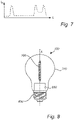
- Fig. 6 shows a lighting device 800 according to an exemplifying embodiment of the present invention.
- the lighting device 800 comprises a LED filament arrangement 100, e.g. according to Fig. 2 or Fig. 5 .
- the lighting device 800 further comprises an electrical connection 830 (e.g. a cap) connected to the LED filament arrangement 120 for a supply of current to the plurality of LEDs 140.
- the lighting device 800 further comprises a control unit 850 coupled to the electrical connection, wherein the control unit 850 is configured to control the supply of current to the plurality of LEDs 140.
- the control unit 850 may be configured to control and/or vary the supply of current to the plurality of LEDs 140 such that gentle fluctuations in intensity and/or luminous flux is obtained.
- the lighting device 800 comprises two electrical circuits 200a, 200b for a supply of current to the plurality of LEDs 140, in contrast to the single electrical circuit 200 of the LED filament arrangement 100 of Fig. 5 . More specifically, the first and second subsets, S 1 , S 2 , of LEDs 140 are connected to a first electrical circuit 200a, and the third subset, S 3 , of LEDs 140 is connected to the second electrical circuit 200b.
- the first and second electrical circuits 200a, 200b are electrically isolated from each other. It should be noted, however, that the LED filament arrangement 100 of Fig. 6 may alternatively comprise an arbitrary number of electrical circuits.
- the control unit 850 may be configured to control the supply of current individually to each electrical circuit of the plurality of electrical circuits.
- the control unit 850 may supply one or more currents, I i , to one or more first electrical circuits of the plurality of electrical circuits, and supply one or more currents, I j , to at least one or more second electrical circuits of the plurality of electrical circuits, wherein Ii ⁇ I j .
- I i currents
- I j currents of the plurality of electrical circuits
- the control unit 850 may supply a first current, I 1 , to the first electrical circuit 200a and supply a second current, I 2 , to the second electrical circuit 200b.
- the control unit 850 may hereby control and/or vary the first and second currents, I 1 and I 2 , such that 0.5 I 2 ⁇ I 1 ⁇ 0.9 I 2 is fulfilled.
- the control unit 850 of the lighting device 800 may further comprise a random current generator configured to supply current randomly to the plurality of LEDs 140 of the LED filament arrangement 100. This is schematically shown in Fig. 7 by the intensity, I v , of the LED filament arrangement 100 along the length, L, of the LED filament arrangement 100.
- the lighting arrangement 300 may comprise a LED filament arrangement 100 or a lighting device which in turn comprises a LED filament arrangment 100, according to any previously exemplified embodiment of the present invention.
- the lighting arrangement 300 further comprises a cover 310 of light-transmissive material, which material preferably is translucent and more preferably transparent.
- the cover 310 is exemplified as being bulb-shaped.
- the lighting arrangement 300 further comprises an electrical connection 830 connected to the LED filament arrangement 100 for a supply of current to the plurality of LEDs 140 of the LED filament arrangement 100.
- the lighting arrangement 300 further comprises a control unit 850 which is configured to control the supply of current to the plurality of LEDs of the LED filament arrangement 100.
- one or more of the LED filament arrangement(s) 100, LED filament(s) 120, the LEDs 140, etc. may have different shapes, dimensions and/or sizes than those depicted/described.
Landscapes
- Engineering & Computer Science (AREA)
- Physics & Mathematics (AREA)
- Microelectronics & Electronic Packaging (AREA)
- Optics & Photonics (AREA)
- General Engineering & Computer Science (AREA)
- Non-Portable Lighting Devices Or Systems Thereof (AREA)
- Led Device Packages (AREA)
- Resistance Heating (AREA)
- Circuit Arrangement For Electric Light Sources In General (AREA)
Claims (15)
- Leuchtdioden-Filamentanordnung, LED-Filamentanordnung, (100), umfassendmindestens ein LED-Filament (120), umfassend eine Anordnung einer Vielzahl von Leuchtdioden (140), LEDs, die auf einem länglichen Substrat (70) angeordnet sind,wobei das mindestens eine LED-Filament mindestens eine erste Teilmenge, S1 aus mindestens zwei LEDs, und mindestens eine zweite Teilmenge, S2, aus mindestens zwei LEDs umfasst, wobei sich die erste Teilmenge, S1, aus LEDs von der zweiten Teilmenge, S2, aus LEDs unterscheidet, dadurch gekennzeichnet, dassdie LEDs der ersten Teilmenge, S1, in Reihe gekoppelt sind, und die LEDs der zweiten Teilmenge, S2, parallel gekoppelt sind, sodass sich der Lichtstrom, Φ1, der einzelnen LEDs der ersten Teilmenge, S1, vom Lichtstrom, Φ2, der einzelnen LEDs der zweiten Teilmenge, S2, während des Betriebs der LED-Filamentanordnung unterscheidet.
- LED-Filamentanordnung nach Anspruch 1, ferner umfassend mindestens eine dritte Teilmenge, S3, aus mindestens zwei LEDs, wobei sich die dritte Teilmenge, S3, von LEDs von der ersten Teilmenge, S1, aus LEDs und der zweiten Teilmenge, S2, aus LEDs unterscheidet,
wobei die LEDs der dritten Teilmenge, S3, parallel gekoppelt sind. - LED-Filamentanordnung nach Anspruch 1 oder 2, umfassend eine einzelne elektrische Schaltung (200) für eine Zufuhr von Strom zu der Vielzahl von LEDs.
- LED-Filamentanordnung nach Anspruch 1 oder 2, umfassend eine Vielzahl von elektrischen Schaltungen (200a, 200b) für eine Zufuhr von Strom zu der Vielzahl von LEDs.
- LED-Filamentanordnung nach einem der vorstehenden Ansprüche, wobei die LEDs äquidistant auf dem Substrat angeordnet sind.
- LED-Filamentanordnung nach einem der vorstehenden Ansprüche, ferner umfassend ein Verkapselungsmittel (250), umfassend ein lichtdurchlässiges Material, wobei das Verkapselungsmittel die Vielzahl von LEDs mindestens teilweise umschließt,
- LED-Filamentanordnung nach Anspruch 6, wobei das Verkapselungsmittel ferner ein Lumineszenzmaterial umfasst und konfiguriert ist, um das von der Vielzahl von LEDs emittierte Licht mindestens teilweise umzuwandeln.
- LED-Filamentanordnung nach Anspruch 6 oder 7, wobei das Verkapselungsmittel (250) ferner lichtstreuende Partikel umfasst, die angeordnet sind, um das von der Vielzahl von LEDs emittierte Licht zu streuen.
- LED-Filamentanordnung nach einem der vorstehenden Ansprüche, wobei die Vielzahl von LEDs die gleiche Farbe oder Farbtemperatur aufweist.
- Beleuchtungsvorrichtung (800), umfassendeine LED-Filamentanordnung nach einem der vorstehenden Ansprüche, mindestens eine elektrische Verbindung (830), die mit der LED-Filamentanordnung für eine Zufuhr von Strom zu der Vielzahl von LEDs verbunden ist, undeine Steuereinheit (850), die mit der mindestens einen elektrischen Verbindung gekoppelt ist, wobei die Steuereinheit konfiguriert ist, um die Zufuhr von Strom zu der Vielzahl von LEDs zu steuern.
- Beleuchtungsvorrichtung nach Anspruch 10, wobei die Steuereinheit einen Zufallsstromgenerator umfasst, der konfiguriert ist, um der Vielzahl von LEDs Strom zuzuführen, der zufällig variiert.
- Beleuchtungsvorrichtung nach Anspruch 10 oder 11, umfassend
mindestens eine LED-Filamentanordnung nach Anspruch 4, wobei die Steuereinheit konfiguriert ist, um die Zufuhr von Strom einzeln zu jeder elektrischen Schaltung der Vielzahl von elektrischen Schaltungen zu steuern. - Beleuchtungsvorrichtung nach Anspruch 12, wobei die Steuereinheit ferner konfiguriert ist, um mindestens einen ersten Strom, I1, mindestens einer ersten elektrischen Schaltung (200a) der Vielzahl von elektrischen Schaltungen zuzuführen, und mindestens einen zweiten Strom, I2, mindestens einer zweiten elektrischen Schaltung (200b) der Vielzahl von elektrischen Schaltungen zuzuführen,
wobei I1 ≠ I2. - Beleuchtungsvorrichtung nach Anspruch 13, wobei 0,5 I2 < I1< 0,9 I2.
- Beleuchtungsanordnung (300), umfassendeine LED-Filamentanordnung nach einem der Ansprüche 1-9 oder eine Beleuchtungsvorrichtung nach einem der Ansprüche 10-14,eine Abdeckung (310), umfassend ein mindestens teilweise lichtdurchlässiges Material, wobei die Abdeckung die LED-Filamentanordnung mindestens teilweise umschließt.
Applications Claiming Priority (2)
| Application Number | Priority Date | Filing Date | Title |
|---|---|---|---|
| EP19188516 | 2019-07-26 | ||
| PCT/EP2020/070093 WO2021018606A1 (en) | 2019-07-26 | 2020-07-16 | Led filament arrangement |
Publications (2)
| Publication Number | Publication Date |
|---|---|
| EP4004432A1 EP4004432A1 (de) | 2022-06-01 |
| EP4004432B1 true EP4004432B1 (de) | 2022-11-16 |
Family
ID=67439030
Family Applications (1)
| Application Number | Title | Priority Date | Filing Date |
|---|---|---|---|
| EP20739398.4A Active EP4004432B1 (de) | 2019-07-26 | 2020-07-16 | Led-filament-anordnung |
Country Status (7)
| Country | Link |
|---|---|
| US (1) | US11739885B2 (de) |
| EP (1) | EP4004432B1 (de) |
| JP (1) | JP7249088B2 (de) |
| CN (1) | CN114174715B (de) |
| ES (1) | ES2935836T3 (de) |
| PL (1) | PL4004432T3 (de) |
| WO (1) | WO2021018606A1 (de) |
Families Citing this family (2)
| Publication number | Priority date | Publication date | Assignee | Title |
|---|---|---|---|---|
| CN116457605A (zh) | 2020-11-03 | 2023-07-18 | 昕诺飞控股有限公司 | Led灯丝装置 |
| WO2023131551A1 (en) * | 2022-01-10 | 2023-07-13 | Signify Holding B.V. | Led filament for illumination and disinfection |
Family Cites Families (24)
| Publication number | Priority date | Publication date | Assignee | Title |
|---|---|---|---|---|
| US5463280A (en) * | 1994-03-03 | 1995-10-31 | National Service Industries, Inc. | Light emitting diode retrofit lamp |
| US7405715B2 (en) | 2001-08-09 | 2008-07-29 | Guzman Robert G | LED light apparatus with instantly adjustable color intensity |
| US8052303B2 (en) | 2006-09-12 | 2011-11-08 | Huizhou Light Engine Ltd. | Integrally formed single piece light emitting diode light wire and uses thereof |
| PL2061991T3 (pl) | 2006-09-12 | 2011-08-31 | Paul Lo | Integralnie utworzony jednoelementowy przewód świetlny z diod elektroluminescencyjnych |
| ES2427280T3 (es) * | 2009-03-12 | 2013-10-29 | Koninklijke Philips N.V. | Iluminación con LED con comportamiento de temperatura de color de lámpara incandescente |
| KR20110121927A (ko) | 2010-05-03 | 2011-11-09 | 삼성엘이디 주식회사 | 발광소자 패키지를 이용한 조명 장치 |
| RU2546469C2 (ru) * | 2010-09-08 | 2015-04-10 | Чжэцзян Ледисон Оптоэлектроникс Ко., Лтд. | Светодиодная лампа |
| US8314566B2 (en) * | 2011-02-22 | 2012-11-20 | Quarkstar Llc | Solid state lamp using light emitting strips |
| JP6330175B2 (ja) | 2013-04-17 | 2018-05-30 | 株式会社エルム | 農業用led照明装置 |
| JP6221456B2 (ja) | 2013-07-23 | 2017-11-01 | 日亜化学工業株式会社 | 発光装置及び照明装置 |
| US11259372B2 (en) * | 2015-06-10 | 2022-02-22 | Zhejiang Super Lighting Electric Appliance Co., Ltd | High-efficiency LED light bulb with LED filament therein |
| CN104948958A (zh) | 2015-07-01 | 2015-09-30 | 上海顿格电子贸易有限公司 | 一种利用热敏电阻限流的led灯 |
| CA2987969C (en) | 2015-07-20 | 2023-01-03 | Jiaxing Super Lighting Electric Appliance Co., Ltd | Led tube lamp |
| KR20170022293A (ko) * | 2015-08-20 | 2017-03-02 | 한국광기술원 | 필라멘트형 엘이디 광원 및 이를 이용한 엘이디 벌브 |
| JP2017062935A (ja) | 2015-09-24 | 2017-03-30 | 東芝ライテック株式会社 | ランプ装置 |
| FR3045777B1 (fr) * | 2015-12-22 | 2020-06-05 | Led-Ner | Filament led avec regulateur de courant et dispositif d'eclairage a filaments led |
| MY194801A (en) * | 2017-02-27 | 2022-12-16 | Robert Bentley Chelf | Low voltage led filament array lighting |
| DE102017104170A1 (de) | 2017-02-28 | 2018-08-30 | ambigence GmbH & Co. KG | Wand eines Möbelkorpus, Verfahren zur Herstellung einer solchen Wand und Möbelkorpus oder Möbel mit einer solchen Wand |
| CN110573791B (zh) | 2017-05-02 | 2022-03-04 | 昕诺飞控股有限公司 | 照明装置和灯具 |
| US10260683B2 (en) | 2017-05-10 | 2019-04-16 | Cree, Inc. | Solid-state lamp with LED filaments having different CCT's |
| CN107202256A (zh) | 2017-06-22 | 2017-09-26 | 深圳市瑞丰光电子股份有限公司 | 一种可调光led模组 |
| CN207778066U (zh) * | 2017-10-13 | 2018-08-28 | 中国计量科学研究院 | 一种总光通量标准灯 |
| CN107846754A (zh) | 2017-11-23 | 2018-03-27 | 江门市宇之光照明科技有限公司 | 一种可分段调光的led灯丝灯 |
| RU183335U1 (ru) * | 2018-02-02 | 2018-09-18 | Евгений Михайлович Силкин | Светодиодная филаментная лампа |
-
2020
- 2020-07-16 ES ES20739398T patent/ES2935836T3/es active Active
- 2020-07-16 US US17/630,100 patent/US11739885B2/en active Active
- 2020-07-16 EP EP20739398.4A patent/EP4004432B1/de active Active
- 2020-07-16 CN CN202080053795.6A patent/CN114174715B/zh active Active
- 2020-07-16 WO PCT/EP2020/070093 patent/WO2021018606A1/en unknown
- 2020-07-16 PL PL20739398.4T patent/PL4004432T3/pl unknown
- 2020-07-16 JP JP2022501152A patent/JP7249088B2/ja active Active
Also Published As
| Publication number | Publication date |
|---|---|
| JP2022535616A (ja) | 2022-08-09 |
| CN114174715A (zh) | 2022-03-11 |
| US20220268404A1 (en) | 2022-08-25 |
| WO2021018606A1 (en) | 2021-02-04 |
| CN114174715B (zh) | 2024-03-29 |
| ES2935836T3 (es) | 2023-03-10 |
| PL4004432T3 (pl) | 2023-04-17 |
| JP7249088B2 (ja) | 2023-03-30 |
| EP4004432A1 (de) | 2022-06-01 |
| US11739885B2 (en) | 2023-08-29 |
Similar Documents
| Publication | Publication Date | Title |
|---|---|---|
| EP3775674B1 (de) | Led-glühlampe in kerzenlichtoptik | |
| CN114731748A (zh) | Led灯丝以及led灯丝灯 | |
| EP4004432B1 (de) | Led-filament-anordnung | |
| US11913608B2 (en) | LED filament arrangement | |
| JP7461956B2 (ja) | Ledフィラメント構成 | |
| US11739886B2 (en) | LED filament arrangement | |
| EP4045838B1 (de) | Led-glühlampe in kerzenlichtoptik | |
| WO2020229462A1 (en) | Led filament arrangement | |
| US20240003505A1 (en) | Led filament | |
| US20220373141A1 (en) | Led filament arrangement | |
| US20220364685A1 (en) | Led filament arrangement | |
| WO2023131551A1 (en) | Led filament for illumination and disinfection |
Legal Events
| Date | Code | Title | Description |
|---|---|---|---|
| STAA | Information on the status of an ep patent application or granted ep patent |
Free format text: STATUS: UNKNOWN |
|
| STAA | Information on the status of an ep patent application or granted ep patent |
Free format text: STATUS: THE INTERNATIONAL PUBLICATION HAS BEEN MADE |
|
| PUAI | Public reference made under article 153(3) epc to a published international application that has entered the european phase |
Free format text: ORIGINAL CODE: 0009012 |
|
| STAA | Information on the status of an ep patent application or granted ep patent |
Free format text: STATUS: REQUEST FOR EXAMINATION WAS MADE |
|
| 17P | Request for examination filed |
Effective date: 20220228 |
|
| AK | Designated contracting states |
Kind code of ref document: A1 Designated state(s): AL AT BE BG CH CY CZ DE DK EE ES FI FR GB GR HR HU IE IS IT LI LT LU LV MC MK MT NL NO PL PT RO RS SE SI SK SM TR |
|
| GRAP | Despatch of communication of intention to grant a patent |
Free format text: ORIGINAL CODE: EPIDOSNIGR1 |
|
| STAA | Information on the status of an ep patent application or granted ep patent |
Free format text: STATUS: GRANT OF PATENT IS INTENDED |
|
| RIC1 | Information provided on ipc code assigned before grant |
Ipc: F21Y 115/10 20160101ALI20220513BHEP Ipc: F21K 9/232 20160101AFI20220513BHEP |
|
| DAV | Request for validation of the european patent (deleted) | ||
| DAX | Request for extension of the european patent (deleted) | ||
| INTG | Intention to grant announced |
Effective date: 20220610 |
|
| GRAS | Grant fee paid |
Free format text: ORIGINAL CODE: EPIDOSNIGR3 |
|
| GRAA | (expected) grant |
Free format text: ORIGINAL CODE: 0009210 |
|
| STAA | Information on the status of an ep patent application or granted ep patent |
Free format text: STATUS: THE PATENT HAS BEEN GRANTED |
|
| AK | Designated contracting states |
Kind code of ref document: B1 Designated state(s): AL AT BE BG CH CY CZ DE DK EE ES FI FR GB GR HR HU IE IS IT LI LT LU LV MC MK MT NL NO PL PT RO RS SE SI SK SM TR |
|
| REG | Reference to a national code |
Ref country code: GB Ref legal event code: FG4D |
|
| REG | Reference to a national code |
Ref country code: CH Ref legal event code: EP |
|
| REG | Reference to a national code |
Ref country code: IE Ref legal event code: FG4D |
|
| REG | Reference to a national code |
Ref country code: DE Ref legal event code: R096 Ref document number: 602020006352 Country of ref document: DE |
|
| REG | Reference to a national code |
Ref country code: AT Ref legal event code: REF Ref document number: 1531964 Country of ref document: AT Kind code of ref document: T Effective date: 20221215 |
|
| REG | Reference to a national code |
Ref country code: SE Ref legal event code: TRGR |
|
| REG | Reference to a national code |
Ref country code: LT Ref legal event code: MG9D Ref country code: ES Ref legal event code: FG2A Ref document number: 2935836 Country of ref document: ES Kind code of ref document: T3 Effective date: 20230310 |
|
| REG | Reference to a national code |
Ref country code: NL Ref legal event code: MP Effective date: 20221116 |
|
| REG | Reference to a national code |
Ref country code: AT Ref legal event code: MK05 Ref document number: 1531964 Country of ref document: AT Kind code of ref document: T Effective date: 20221116 |
|
| PG25 | Lapsed in a contracting state [announced via postgrant information from national office to epo] |
Ref country code: PT Free format text: LAPSE BECAUSE OF FAILURE TO SUBMIT A TRANSLATION OF THE DESCRIPTION OR TO PAY THE FEE WITHIN THE PRESCRIBED TIME-LIMIT Effective date: 20230316 Ref country code: NO Free format text: LAPSE BECAUSE OF FAILURE TO SUBMIT A TRANSLATION OF THE DESCRIPTION OR TO PAY THE FEE WITHIN THE PRESCRIBED TIME-LIMIT Effective date: 20230216 Ref country code: LT Free format text: LAPSE BECAUSE OF FAILURE TO SUBMIT A TRANSLATION OF THE DESCRIPTION OR TO PAY THE FEE WITHIN THE PRESCRIBED TIME-LIMIT Effective date: 20221116 Ref country code: FI Free format text: LAPSE BECAUSE OF FAILURE TO SUBMIT A TRANSLATION OF THE DESCRIPTION OR TO PAY THE FEE WITHIN THE PRESCRIBED TIME-LIMIT Effective date: 20221116 Ref country code: AT Free format text: LAPSE BECAUSE OF FAILURE TO SUBMIT A TRANSLATION OF THE DESCRIPTION OR TO PAY THE FEE WITHIN THE PRESCRIBED TIME-LIMIT Effective date: 20221116 |
|
| PG25 | Lapsed in a contracting state [announced via postgrant information from national office to epo] |
Ref country code: RS Free format text: LAPSE BECAUSE OF FAILURE TO SUBMIT A TRANSLATION OF THE DESCRIPTION OR TO PAY THE FEE WITHIN THE PRESCRIBED TIME-LIMIT Effective date: 20221116 Ref country code: LV Free format text: LAPSE BECAUSE OF FAILURE TO SUBMIT A TRANSLATION OF THE DESCRIPTION OR TO PAY THE FEE WITHIN THE PRESCRIBED TIME-LIMIT Effective date: 20221116 Ref country code: IS Free format text: LAPSE BECAUSE OF FAILURE TO SUBMIT A TRANSLATION OF THE DESCRIPTION OR TO PAY THE FEE WITHIN THE PRESCRIBED TIME-LIMIT Effective date: 20230316 Ref country code: HR Free format text: LAPSE BECAUSE OF FAILURE TO SUBMIT A TRANSLATION OF THE DESCRIPTION OR TO PAY THE FEE WITHIN THE PRESCRIBED TIME-LIMIT Effective date: 20221116 Ref country code: GR Free format text: LAPSE BECAUSE OF FAILURE TO SUBMIT A TRANSLATION OF THE DESCRIPTION OR TO PAY THE FEE WITHIN THE PRESCRIBED TIME-LIMIT Effective date: 20230217 |
|
| P01 | Opt-out of the competence of the unified patent court (upc) registered |
Effective date: 20230425 |
|
| PG25 | Lapsed in a contracting state [announced via postgrant information from national office to epo] |
Ref country code: NL Free format text: LAPSE BECAUSE OF FAILURE TO SUBMIT A TRANSLATION OF THE DESCRIPTION OR TO PAY THE FEE WITHIN THE PRESCRIBED TIME-LIMIT Effective date: 20221116 |
|
| PG25 | Lapsed in a contracting state [announced via postgrant information from national office to epo] |
Ref country code: SM Free format text: LAPSE BECAUSE OF FAILURE TO SUBMIT A TRANSLATION OF THE DESCRIPTION OR TO PAY THE FEE WITHIN THE PRESCRIBED TIME-LIMIT Effective date: 20221116 Ref country code: RO Free format text: LAPSE BECAUSE OF FAILURE TO SUBMIT A TRANSLATION OF THE DESCRIPTION OR TO PAY THE FEE WITHIN THE PRESCRIBED TIME-LIMIT Effective date: 20221116 Ref country code: EE Free format text: LAPSE BECAUSE OF FAILURE TO SUBMIT A TRANSLATION OF THE DESCRIPTION OR TO PAY THE FEE WITHIN THE PRESCRIBED TIME-LIMIT Effective date: 20221116 Ref country code: DK Free format text: LAPSE BECAUSE OF FAILURE TO SUBMIT A TRANSLATION OF THE DESCRIPTION OR TO PAY THE FEE WITHIN THE PRESCRIBED TIME-LIMIT Effective date: 20221116 Ref country code: CZ Free format text: LAPSE BECAUSE OF FAILURE TO SUBMIT A TRANSLATION OF THE DESCRIPTION OR TO PAY THE FEE WITHIN THE PRESCRIBED TIME-LIMIT Effective date: 20221116 |
|
| REG | Reference to a national code |
Ref country code: DE Ref legal event code: R097 Ref document number: 602020006352 Country of ref document: DE |
|
| PG25 | Lapsed in a contracting state [announced via postgrant information from national office to epo] |
Ref country code: SK Free format text: LAPSE BECAUSE OF FAILURE TO SUBMIT A TRANSLATION OF THE DESCRIPTION OR TO PAY THE FEE WITHIN THE PRESCRIBED TIME-LIMIT Effective date: 20221116 Ref country code: AL Free format text: LAPSE BECAUSE OF FAILURE TO SUBMIT A TRANSLATION OF THE DESCRIPTION OR TO PAY THE FEE WITHIN THE PRESCRIBED TIME-LIMIT Effective date: 20221116 |
|
| PLBE | No opposition filed within time limit |
Free format text: ORIGINAL CODE: 0009261 |
|
| STAA | Information on the status of an ep patent application or granted ep patent |
Free format text: STATUS: NO OPPOSITION FILED WITHIN TIME LIMIT |
|
| 26N | No opposition filed |
Effective date: 20230817 |
|
| PGFP | Annual fee paid to national office [announced via postgrant information from national office to epo] |
Ref country code: IT Payment date: 20230731 Year of fee payment: 4 Ref country code: ES Payment date: 20230816 Year of fee payment: 4 |
|
| PG25 | Lapsed in a contracting state [announced via postgrant information from national office to epo] |
Ref country code: SI Free format text: LAPSE BECAUSE OF FAILURE TO SUBMIT A TRANSLATION OF THE DESCRIPTION OR TO PAY THE FEE WITHIN THE PRESCRIBED TIME-LIMIT Effective date: 20221116 |
|
| PGFP | Annual fee paid to national office [announced via postgrant information from national office to epo] |
Ref country code: SE Payment date: 20230726 Year of fee payment: 4 Ref country code: PL Payment date: 20230705 Year of fee payment: 4 Ref country code: FR Payment date: 20230725 Year of fee payment: 4 Ref country code: DE Payment date: 20230928 Year of fee payment: 4 |
|
| PG25 | Lapsed in a contracting state [announced via postgrant information from national office to epo] |
Ref country code: MC Free format text: LAPSE BECAUSE OF FAILURE TO SUBMIT A TRANSLATION OF THE DESCRIPTION OR TO PAY THE FEE WITHIN THE PRESCRIBED TIME-LIMIT Effective date: 20221116 |
|
| PG25 | Lapsed in a contracting state [announced via postgrant information from national office to epo] |
Ref country code: MC Free format text: LAPSE BECAUSE OF FAILURE TO SUBMIT A TRANSLATION OF THE DESCRIPTION OR TO PAY THE FEE WITHIN THE PRESCRIBED TIME-LIMIT Effective date: 20221116 |
|
| REG | Reference to a national code |
Ref country code: CH Ref legal event code: PL |
|
| REG | Reference to a national code |
Ref country code: BE Ref legal event code: MM Effective date: 20230731 |
|
| PG25 | Lapsed in a contracting state [announced via postgrant information from national office to epo] |
Ref country code: LU Free format text: LAPSE BECAUSE OF NON-PAYMENT OF DUE FEES Effective date: 20230716 |
|
| PG25 | Lapsed in a contracting state [announced via postgrant information from national office to epo] |
Ref country code: LU Free format text: LAPSE BECAUSE OF NON-PAYMENT OF DUE FEES Effective date: 20230716 |
|
| REG | Reference to a national code |
Ref country code: IE Ref legal event code: MM4A |
|
| PG25 | Lapsed in a contracting state [announced via postgrant information from national office to epo] |
Ref country code: CH Free format text: LAPSE BECAUSE OF NON-PAYMENT OF DUE FEES Effective date: 20230731 |