EP3759453B1 - Verbesserungen an oder im zusammenhang mit der überwachung von fluidrohren - Google Patents
Verbesserungen an oder im zusammenhang mit der überwachung von fluidrohren Download PDFInfo
- Publication number
- EP3759453B1 EP3759453B1 EP19712007.4A EP19712007A EP3759453B1 EP 3759453 B1 EP3759453 B1 EP 3759453B1 EP 19712007 A EP19712007 A EP 19712007A EP 3759453 B1 EP3759453 B1 EP 3759453B1
- Authority
- EP
- European Patent Office
- Prior art keywords
- pipe
- fibre
- das
- microduct
- along
- Prior art date
- Legal status (The legal status is an assumption and is not a legal conclusion. Google has not performed a legal analysis and makes no representation as to the accuracy of the status listed.)
- Active
Links
Images


Classifications
-
- G—PHYSICS
- G01—MEASURING; TESTING
- G01M—TESTING STATIC OR DYNAMIC BALANCE OF MACHINES OR STRUCTURES; TESTING OF STRUCTURES OR APPARATUS, NOT OTHERWISE PROVIDED FOR
- G01M3/00—Investigating fluid-tightness of structures
- G01M3/38—Investigating fluid-tightness of structures by using light
-
- G—PHYSICS
- G01—MEASURING; TESTING
- G01B—MEASURING LENGTH, THICKNESS OR SIMILAR LINEAR DIMENSIONS; MEASURING ANGLES; MEASURING AREAS; MEASURING IRREGULARITIES OF SURFACES OR CONTOURS
- G01B11/00—Measuring arrangements characterised by the use of optical techniques
-
- G—PHYSICS
- G01—MEASURING; TESTING
- G01B—MEASURING LENGTH, THICKNESS OR SIMILAR LINEAR DIMENSIONS; MEASURING ANGLES; MEASURING AREAS; MEASURING IRREGULARITIES OF SURFACES OR CONTOURS
- G01B17/00—Measuring arrangements characterised by the use of infrasonic, sonic or ultrasonic vibrations
-
- G—PHYSICS
- G01—MEASURING; TESTING
- G01M—TESTING STATIC OR DYNAMIC BALANCE OF MACHINES OR STRUCTURES; TESTING OF STRUCTURES OR APPARATUS, NOT OTHERWISE PROVIDED FOR
- G01M11/00—Testing of optical apparatus; Testing structures by optical methods not otherwise provided for
- G01M11/08—Testing mechanical properties
- G01M11/083—Testing mechanical properties by using an optical fiber in contact with the device under test [DUT]
- G01M11/085—Testing mechanical properties by using an optical fiber in contact with the device under test [DUT] the optical fiber being on or near the surface of the DUT
-
- G—PHYSICS
- G01—MEASURING; TESTING
- G01M—TESTING STATIC OR DYNAMIC BALANCE OF MACHINES OR STRUCTURES; TESTING OF STRUCTURES OR APPARATUS, NOT OTHERWISE PROVIDED FOR
- G01M11/00—Testing of optical apparatus; Testing structures by optical methods not otherwise provided for
- G01M11/08—Testing mechanical properties
- G01M11/083—Testing mechanical properties by using an optical fiber in contact with the device under test [DUT]
- G01M11/086—Details about the embedment of the optical fiber within the DUT
-
- G—PHYSICS
- G01—MEASURING; TESTING
- G01M—TESTING STATIC OR DYNAMIC BALANCE OF MACHINES OR STRUCTURES; TESTING OF STRUCTURES OR APPARATUS, NOT OTHERWISE PROVIDED FOR
- G01M3/00—Investigating fluid-tightness of structures
- G01M3/02—Investigating fluid-tightness of structures by using fluid or vacuum
- G01M3/04—Investigating fluid-tightness of structures by using fluid or vacuum by detecting the presence of fluid at the leakage point
- G01M3/042—Investigating fluid-tightness of structures by using fluid or vacuum by detecting the presence of fluid at the leakage point by using materials which expand, contract, disintegrate, or decompose in contact with a fluid
- G01M3/045—Investigating fluid-tightness of structures by using fluid or vacuum by detecting the presence of fluid at the leakage point by using materials which expand, contract, disintegrate, or decompose in contact with a fluid with electrical detection means
- G01M3/047—Investigating fluid-tightness of structures by using fluid or vacuum by detecting the presence of fluid at the leakage point by using materials which expand, contract, disintegrate, or decompose in contact with a fluid with electrical detection means with photo-electrical detection means, e.g. using optical fibres
-
- G—PHYSICS
- G01—MEASURING; TESTING
- G01M—TESTING STATIC OR DYNAMIC BALANCE OF MACHINES OR STRUCTURES; TESTING OF STRUCTURES OR APPARATUS, NOT OTHERWISE PROVIDED FOR
- G01M3/00—Investigating fluid-tightness of structures
- G01M3/02—Investigating fluid-tightness of structures by using fluid or vacuum
- G01M3/04—Investigating fluid-tightness of structures by using fluid or vacuum by detecting the presence of fluid at the leakage point
- G01M3/24—Investigating fluid-tightness of structures by using fluid or vacuum by detecting the presence of fluid at the leakage point using infrasonic, sonic or ultrasonic vibrations
- G01M3/243—Investigating fluid-tightness of structures by using fluid or vacuum by detecting the presence of fluid at the leakage point using infrasonic, sonic or ultrasonic vibrations for pipes
-
- G—PHYSICS
- G01—MEASURING; TESTING
- G01M—TESTING STATIC OR DYNAMIC BALANCE OF MACHINES OR STRUCTURES; TESTING OF STRUCTURES OR APPARATUS, NOT OTHERWISE PROVIDED FOR
- G01M5/00—Investigating the elasticity of structures, e.g. deflection of bridges or air-craft wings
- G01M5/0025—Investigating the elasticity of structures, e.g. deflection of bridges or air-craft wings of elongated objects, e.g. pipes, masts, towers or railways
-
- G—PHYSICS
- G01—MEASURING; TESTING
- G01M—TESTING STATIC OR DYNAMIC BALANCE OF MACHINES OR STRUCTURES; TESTING OF STRUCTURES OR APPARATUS, NOT OTHERWISE PROVIDED FOR
- G01M5/00—Investigating the elasticity of structures, e.g. deflection of bridges or air-craft wings
- G01M5/0033—Investigating the elasticity of structures, e.g. deflection of bridges or air-craft wings by determining damage, crack or wear
-
- G—PHYSICS
- G01—MEASURING; TESTING
- G01M—TESTING STATIC OR DYNAMIC BALANCE OF MACHINES OR STRUCTURES; TESTING OF STRUCTURES OR APPARATUS, NOT OTHERWISE PROVIDED FOR
- G01M5/00—Investigating the elasticity of structures, e.g. deflection of bridges or air-craft wings
- G01M5/0066—Investigating the elasticity of structures, e.g. deflection of bridges or air-craft wings by exciting or detecting vibration or acceleration
-
- G—PHYSICS
- G01—MEASURING; TESTING
- G01M—TESTING STATIC OR DYNAMIC BALANCE OF MACHINES OR STRUCTURES; TESTING OF STRUCTURES OR APPARATUS, NOT OTHERWISE PROVIDED FOR
- G01M5/00—Investigating the elasticity of structures, e.g. deflection of bridges or air-craft wings
- G01M5/0091—Investigating the elasticity of structures, e.g. deflection of bridges or air-craft wings by using electromagnetic excitation or detection
Definitions
- the present invention relates to improvements in or relating to the monitoring of fluid pipes.
- the present invention relates to techniques for monitoring fluid pipes, methods of installing sensing apparatus and uses of sensing apparatus for monitoring the condition of pipes.
- the present invention may further relate to the monitoring of activity adjacent to pipes and/or methods for locating pipes buried underground.
- modem services rely upon a network of pipes to carry or distribute fluids. Examples include fresh water, waste water and sewage, and fuels such as oil or gas. It is common to monitor the operation of the network and the condition of pipes. In this manner, blockages, leaks or other issues can be identified and scheduled for repair.
- monitoring may be achieved by visual inspection of the pipe exterior.
- pipes are not accessible to visual inspection, being buried underground. Accordingly, pressure/audio sensors or the like may be utilised to detect vibrations of the pipe and thereby provide information on conditions within a pipe.
- pressure/audio sensors can be permanently fitted periodically along the pipe, the sensor spacing being determined by a combination of sensitivity, expense and convenience.
- these sensors might be located adjacent to pipe access points such as valve, junction or pump spaces. This has the benefit of enabling sensor signals to be readily relayed away from the pipe and for enabling ready access to fit and check the operation of such sensors.
- Arrangements of this type are able to provide an indication that there is a problem, for instance a leak.
- sensors are widely spaced and it can therefore be difficult to identify a problem.
- a submersible In addition to or in place of permanently fixed sensors, it is possible to monitor the condition of a pipe by using a drone or the like introduced into the pipe.
- the submersible is fitted with one or more sensors and moves along a length of pipe between suitable access points. Accordingly, such a method is only applicable where the pipe does have access points suitable for introducing a submersible into the pipe.
- the submersible may move along the pipe under its own power or in response to the fluid flow within the pipe. Since the submersible is moving within the pipe, flow noise associated with this movement or noise associated with powering the submersible may mask sensing of relatively minor problems.
- a submersible is only able to define the location of a problem if it occurs when the submersible is actually passing by the event, the detection is transitory and such that it is not distributed or real-time.
- DAS distributed acoustic sensing
- DAS involves the detection of backscattering of light pulses introduced into an optical fibre. The time of arrival and intensity of the backscattered light is measured for each pulse, the time at which the backscattered light is detected being related to the distance along the fibre the light has travelled before being scattered. Subsequent changes in the reflected intensity of successive pulses from a common region of the fibre correspond to variations in the strain applied to the fibre at that region, for instance due to vibrations experienced by the region of fibre.
- the DAS fibre can act as a plurality of virtual microphones along the length of the fibre and can locate events causing acoustic signals down to an accuracy of around 1 meter.
- DAS has been applied to above ground pipes (and alongside buried pipes when installed at the time of constructing the pipe) by affixing fibres directly to the exterior of such pipes. This provides good acoustic coupling between the fibres, the pipe and the fluids within the pipe. For above ground pipes it also enables ready installation and ready access for maintenance. Nevertheless, such exterior fibres are exposed both to accidental damage and to intentional damage.
- DAS has been applied to buried pipes by burying a DAS fibre in close proximity (typically 20-30cm) to the pipe. Even so, works required for burying a DAS fibre can be expensive and highly disruptive, particularly where the buried pipe runs through an urban area. Additionally, separately buried DAS fibres suffer from limitations in sensitivity, particularly where ground conditions provide poor or highly variable acoustic coupling to the pipe. Furthermore, such separately buried DAS fibres are still susceptible to damage.
- US2011007996A1 discloses a fibre surveillance system for monitoring a pipeline comprising one or more optical fibres acoustically coupled to the pipeline to detect acoustic signals associated with vibrations or other activity near or from the pipeline.
- Optical energy is injected into the optical fibre and an optical detector receives an optical return-signal.
- An analyser is configured to determine operating information about the pipeline based on the optical return-signal.
- US2013319121A1 discloses methods and apparatus for distributed acoustic sensing using a fibre optic distributed acoustic sensing (DAS) apparatus comprising at least one optical fibre deployed to monitor the acoustic response of a cavity to incident acoustic signals.
- the cavity is dimensioned such that the cavity resonates at a desired frequency and thus the relevant sensing portions of the DAS sensor show an enhanced response to acoustic signals which excite resonance in the cavity.
- DAS distributed acoustic sensing
- US2011069302A discloses a method for monitoring for seismic events by interrogating an optic fibre which forms part of an existing communications infrastructure to provide distributed acoustic sensing (DAS).
- DAS distributed acoustic sensing
- a method of monitoring a fluid pipe comprising the steps of: providing a distributed acoustic sensing (DAS) fibre within the pipe; introducing coherent light pulses into the fibre; detecting backscattered light from the fibre; and processing the backscattered light so as to obtain information about the condition of the pipe, wherein the step of providing the DAS fibre within the pipe comprises: transporting a microduct along the pipe, aided by the provision of a sail structure attached to an end of the microduct and pulled along by a fluid flow within the pipe, and, following introduction of the microduct, subsequently blowing the DAS fibre along the microduct.
- DAS distributed acoustic sensing
- DAS fibre By providing a DAS fibre within a pipe, good acoustic coupling between the DAS fibre and the pipe is assured. Accordingly, DAS fibre can be used to detect pipe condition information including pressure waves, temperature changes, flow noise, orifice noise or the like. Where location or sensitivity permits, the DAS fibre may also detect and monitor vibrations from sources outside the pipe such as nearby traffic. Furthermore, a fibre within the pipe is more resistant to accidental damage or intentional damage than an external fibre. Additionally, introducing a fibre within an existing buried pipe can be less disruptive and less expensive than burying a DAS fibre in close proximity to the pipe.
- the pipe may be a pipe carrying any suitable fluid.
- suitable fluids might include but are not limited to: water, waste water, sewage, and fuel such as oil, gas, distillates or the like and chemical or mining products.
- the DAS fibre may be a single fibre.
- the DAS fibre may be a dedicated fibre within a bundle of fibres.
- the bundle of fibres may form a multicore fibre cable.
- the DAS monitoring preferably operates from one end only.
- the DAS fibre may be a single ended fibre.
- a barrier is provided between the DAS fibre and the fluid. This can protect the DAS fibre from damage from the fluid or debris within the fluid.
- the barrier may comprise a coating or cover provided over the DAS fibre.
- the barrier may comprise a coating or cover provided over the multicore fibre.
- the barrier comprises a microduct within which the fibre is provided. The method includes the step of introducing the microduct to the pipe and subsequently blowing the DAS fibre along the microduct.
- the gap may be filled with gel. This can improve acoustic coupling between the DAS fibre and the pipe or fluid within the pipe.
- the method may include the step of introducing a gel between the DAS fibre and the barrier.
- the method may include the step of installing the DAS fibre in the pipe.
- the fibre may be installed temporarily.
- the method may include the step of removing the DAS fibre from the pipe after use.
- Introducing the DAS fibre may include the steps of forming an aperture in the pipe wall and introducing a DAS fibre through the aperture.
- the DAS fibre can then be run along the interior of the pipe to a desired end point or to a desired exit point.
- the method may include the steps of forming an aperture through the pipe wall and removing the DAS fibre from the pipe.
- the aperture may be provided with a fitting operable to provide a seal between the DAS fibre and the edges of the aperture.
- the fitting may be adapted to enable the formation of an aperture.
- the method may comprise the steps of depressurising the fluid pipe before forming the aperture and installing a leak tight coupling around the fibre at each aperture.
- the aperture may be formed and the DAS fibre introduced without depressurising the pipe. Numerous such 'hot tap' techniques are known in the art.
- the microduct is transported along the interior of the pipe by the fluid flow within the pipe. This transport is aided by the provision of a sail structure attached to the microduct.
- the sail structure may be collapsible. This facilitates introduction/removal through the aperture and withdrawal of the DAS fibre against the fluid flow.
- the DAS fibre is blown along the microduct.
- the DAS fibre may run at any suitable position within the cross-section of the pipe.
- the DAS fibre runs within the fluid separated from the pipe walls.
- the DAS fibre may have a neutral buoyancy. This helps to retain a position separated from the pipe walls.
- the DAS fibre may lie alongside a pipe wall. This may be achieved by the DAS fibre having a positive buoyancy or negative buoyancy as appropriate.
- the DAS fibre may be secured to the pipe walls.
- the DAS fibre may be secured to the sides or top of the pipe.
- the DAS fibre may be secured to the base of the pipe. This location may be particularly suitable for pipes that do not carry a full fluid load at all times, for example gravity flow systems, as this ensures that the DAS cable is immersed in the fluid and can thus monitor the fluid flow.
- the DAS fibre may run within a microduct integrally formed within a pipe liner.
- the method may include the additional steps of installing a pipe liner incorporating an integral microduct.
- the method may include the additional steps of blowing DAS fibre along the integrated microduct.
- the microduct and DAS fibre combination are adapted to provide the required buoyancy.
- a pipe liner with an integral microduct may comprise an elongate duct formed from multiple laminated layers of thermoplastic material, where heating means are provided within the pipe liner, the liner adapted to provide a cable duct between two laminate layers and wherein the cable duct is formed from a thermoplastic material having a higher transition temperature than the thermoplastic material forming the laminate layers.
- Such a pipe liner may be installed by the method of inserting the pipe liner into the pipe; heating the pipe liner; and subsequently pressing the pipe liner against the interior surface of the pipe.
- Such a liner and method of installation is disclosed in our earlier application published as WO2016/001659 .
- Substantially the full length of the DAS fibre or at least the full length of the DAS fibre used for sensing may be within the pipe.
- the DAS fibre may include lengths within the pipe and lengths outside the pipe.
- the DAS fibre may lie within the pipe in unencumbered sections of the pipe and may exit and re-enter the pipe on either side of pipe machinery.
- pipe machinery may include, but is not limited to valves, pumps, junctions or the like as well as related building or land assets.
- the DAS fibre may be used to monitor multiple pipe segments.
- the DAS fibre may be spliced to create a continuous link for sensing.
- the lengths of fibre outside the pipe may be utilised for monitoring activity outside the pipe.
- DAS fibre may exit the pipe at pipe machinery and lie buried around the pipe machinery before re-entering the pipe.
- the buried section of the DAS fibre may be used for monitoring activity at or around the pipe machinery. In particular, this might include monitoring access to the pipe machinery, especially in the case of building or land assets, by detecting vehicles or individuals crossing the buried DAS fibre.
- the light emitter may be a laser.
- the emitted light may any suitable wavelength for transmission along and backscattering within the DAS fibre.
- the light emitter and light detector may be integrated into a light transceiver unit.
- Light emission may be controlled in order to vary any one or more of: pulse frequency, pulse length and pulse intensity of the emitted light.
- Detected backscattered light may be processed to determine vibration amplitudes and frequencies experienced by particular scattering points on the fibre and hence particular locations along the pipe.
- the method may include the step of filtering the received vibration signals.
- the filtering may be in respect of time of receipt (and hence location along the DAS fibre) or in respect of vibration frequency, vibration amplitude, or a combination thereof.
- the combination may include matching vibration frequency and amplitude against expected signatures of particular events. This can enable the method to be focussed on detecting or excluding particular sources of vibration. In one example, this could be orifice noise caused by fluid leaking from the pipe.
- the processing unit may be operable to detect vibrations associated with activity outside the pipe. For instance, this may include the detection of traffic on roads overlying or close to a buried pipe.
- the processing and/or filtering of detected light signals may be carried out by a processing unit.
- the processing unit may be in communication with the light detector.
- the processing unit may be in communication with the light emitter.
- the processing unit may be operable to control the light emitter.
- the processing unit may be provided locally to the light detector and the light emitter.
- the light emitter, light detector and processor may be integrated into a pipe sensor unit.
- a sensor unit may be provided with a user interface.
- the user interface may enable a user to control operation of the pipe sensor unit and/or review indications relating to the condition of the monitored pipe.
- the examples not forming part of the claimed subject matter may include the additional step of transmitting data along the DAS fibres.
- the data may be simplex data.
- the data may be transmitted in a non-contact fashion.
- data may be encoded and transmitted by applying vibrations to the pipe, the fluid or to the DAS fibre.
- the vibrations may be applied by a vibrator unit.
- the vibrator unit is directly coupled to the fibre.
- the applied vibrations may be encoded using a dual tone multiple frequency (DTMF) scheme.
- DTMF dual tone multiple frequency
- the vibrator unit may be connected to a processing device or to a sensor operable to sense the condition of the pipe, the condition of pipe machinery, or the presence of personnel. In the case of pipe machinery, this may include sensors monitoring the condition of physical access portals such as doors, gates, lids or the like.
- the encoded data may relate to the output of the processing device or sensor.
- the method may include the additional step of sporadically transmitting a keep- alive signal from the vibrator unit. This can be used to verify continuing correct operation of the vibrator unit. This thereby helps overcome the limitations of simplex data transmission in such circumstances.
- the method may include the additional steps of locating the route of an underground pipe. This may be achieved by successively tamping the ground surface at a number of locations in the vicinity of the suspect route of the pipe; processing the backscattered light so as to determine variations in the magnitude of vibrations due to the tamping at each location and thereby determining the route of the pipe.
- the tamping may be carried out using any suitable tamping device, including both manual and powered devices.
- the method may include the step of filtering backscattered light to select vibrations at frequencies corresponding to those caused by the tamping or having acoustic signatures characteristic of tamping.
- the tamping may be carried out at a series of regularly spaced locations along a line lying across the expected route of the pipe. In some implementations two or more parallel lines of tamping may be carried out. In some implementations, the tamping may be carried out at locations defined by a pre-set grid.
- a method of locating the route of an underground pipe comprising the steps of: providing a DAS fibre within the pipe; introducing coherent light pulses into the fibre; detecting backscattered light from the fibre; successively tamping the ground surface at a number of locations in the vicinity of the suspect route of the pipe; and processing the backscattered light so as to determine variations in the magnitude of vibrations due to the tamping at each location and thereby determining the route of the pipe.
- the method of this example may incorporate any or all features of the first aspect of the present invention.
- a method of transmitting data along a pipe comprising the steps of: providing a DAS fibre within the pipe; introducing coherent light pulses into the fibre; detecting backscattered light from the fibre; applying vibrations to the DAS fibre, the vibrations encoding data; processing the backscattered light so as to detect the applied vibrations.
- an apparatus for transmitting data along a pipe comprising: a distributed acoustic sensing (DAS) fibre provided within the pipe; a light emitter for introducing light pulses into the fibre; a light detector for detecting backscattering of the said light pulses; and a vibrator unit acoustically coupled to the DAS fibre, the vibrator unit operable to apply vibrations to the DAS fibre, the vibrations encoding data.
- DAS distributed acoustic sensing
- a fluid pipe 1 is monitored using a distributed acoustic sensing (DAS) fibre 10.
- DAS distributed acoustic sensing
- the invention is primarily described in terms of monitoring of a pipe carrying water. Nevertheless, the skilled man will appreciate that the invention may be applied to pipes 1 carrying other fluids including, but not limited to, waste water, sewage or fuels such as oil, gas distillates or the like and chemical or mining products.
- the DAS fibre is coupled at one end to a light emitter 101, typically a laser and a light detector 102.
- the light emitter 101 emits light pulses into the DAS fibre.
- the light detector 102 detects backscattered light from the DAS fibre, the time of arrival of the backscattered light following the emission of a pulse relating to the location of the backscattering site along the DAS fibre. Vibrations propagating through the fluid around the DAS fibre 10 result in corresponding vibration of the DAS fibre 10. Vibrations of the fibre cause variation in the backscattering that occurs from each backscattering site. Accordingly, these variations can be used to provide an indication of the vibration experienced by each section of the DAS fibre.
- a processing unit 103 may be provided to process the detected light and thereby provide an output indicative of vibrations imposed upon the DAS fibre 10 along its length.
- the processing unit 103 will typically be local to the light emitter 101 and light detector 102 but may be alternatively provided at a remote location. In the latter case, a communication unit (not shown) would be operable to communicate remotely with the processing unit 103.
- the processing unit 103 may be operable to identify vibrations as being characteristic of particular pipe events. This may be achieved by determining the frequencies or amplitudes of vibrations or by filtering selected frequencies of vibration. Common pipe events that might be detected beyond orifice noise and negative pressure waves indicative of leaks include flow noise, pressure waves indicative of operation of pipe machinery (valves, pumps or the like) or the change of fluid temperature. Where sensitivity permits, events external to the pipe may also be detected and monitored.
- the DAS fibre 10 is provided within pipe 1.
- the pipe 1 has a leak 2
- vibrations 3 characteristic of orifice noise will travel through the fluid until they impinge on the DAS fibre 10.
- Subsequent operation of the processing unit will determine the occurrence of vibrations of the DAS fibre 10 and the position along the DAS fibre 10 at which these vibrations occur. Accordingly, the position of the leak 2 along the length of pipe 1 can also be determined.
- the pipe 1 runs under a road 20.
- Vehicles 21 travelling along the road 20 generate vibrations 22 which can travel though the ground to the pipe 1.
- the vibrations 22 can also be detected on DAS fibre 10.
- the DAS fibre 10 can be used to monitor traffic flow on road 20. In other situations, the DAS fibre 10 can be used to monitor other activity external to the pipe 1.
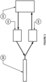
- the DAS fibre 10 is a single dedicated fibre in a multicore cable 11 formed from a plurality of fibres.
- the multicore cable 11 may be provided with a protective exterior coating (not shown).
- the multicore cable 11 is provided within a microduct 12.
- the microduct 12 forms a barrier between the cable 11 and the fluid within pipe 1.
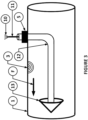
- the microduct 12 is introduced into the pipe 1 through an aperture (not shown) in the pipe wall. As shown in Figures 3 and 4 , typically, this aperture will be provided with a suitable fitting 5 that provides a seal between the microduct 12 and the edges of the aperture. Such a fitting 5 can be installed whilst the pipe 1 is drained of fluid. Alternatively, the fitting 5 can enable the formation of an aperture and the subsequent introduction of a microduct 12 using so called 'hot tap' techniques known in the art that do not require the pipe 1 to be drained. Hot tap techniques are particularly suitable in instances where the DAS fibre 10 is installed temporarily, for instance to establish the location of a suspected leak.
- Non-limiting examples of fittings and techniques for introducing fibres and/or microducts to pipes are also disclosed in our prior patent applications WO2010/029365 , WO2011/135383 , WO2015/001332 , WO2017/085466 and WO2017/081478 .
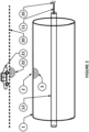
- the microduct 12 After introduction, the microduct 12 is transported along the pipe 1. The microduct 12 is pulled along by fluid flow F within the pipe 1. As is shown in figure 3 , this is aided by the provision of a sail structure 13 attached to the end of the microduct 12. Where the microduct 12 is introduced temporarily, the sail structure 13 may be collapsible. This can aid in subsequently withdrawing the microduct 12 through the fitting. In alternative examples not forming part of the claimed subject matter, the DAS fibre 10 or microduct 12 is towed by a powered submersible introduced into the pipe 1.
- the DAS fibre 10 is blown along the microduct 10.
- the microduct 12 may be filled with acoustic gel (not shown). This can improve acoustic coupling between the microduct 12 and the DAS fibre 10.
- the DAS fibre 10 may exit and re-enter the pipe 1 on either side of the machinery.
- FIG 4 An example of such a situation is shown in figure 4 , where pipe 1 is fitted with an in-line stop valve 4.
- microduct 12 exits the cable on one side of the valve 4 via a fitting 5 providing a seal between the microduct 12 and the edges of an aperture in the pipe 1; and re-enters the pipe 1 on the other side of the valve 4 via a corresponding fitting 5.
- the DAS fibre 10 may run continuously around the valve 4.
- such a bypass may provide a convenient point at which to provide a splice 16 connecting together different sections of DAS fibre 10.
- the processing unit 103 may be operable to disregard backscattered light where the time of detection indicates that it was backscattered from the section of DAS fibre 10 outside the pipe 1. In other embodiments, the processing unit 103 may be operable to separately process light backscattered from the section of DAS fibre 10 outside the pipe 1. This can allow separate monitoring of activity outside the pipe 1.
- an extended section 14 of DAS fibre 10 may be provided. The extended section 14 may be buried around the perimeter 6 of accessible pipe machinery comprising a building or land asset such as a pumping station or the like. Monitoring light backscattered from the extended section 14 can detect vibrations 7 characteristic of the crossing of perimeter 6 by persons or vehicles. This can enable unauthorised perimeter crossings, which may indicate unauthorised access, to be detected.
- the position of the DAS fibre 10 (or microduct 12) within the pipe 1 may be varied as appropriate.
- the microduct 12 containing the DAS fibre 10 runs substantially along the centre of the pipe 1. This position is advantageous in that it equally exposed to leaks from all sides of the pipe 1. It is also relatively simple to allow DAS fibre 10 (or microduct 12) to assume this position within the fluid on introduction, via a neutral buoyancy. Accordingly, this positioning is convenient for temporary installations.
- the DAS fibre 10 or microduct 12 may be desirable to position in an alternative position such as close to a wall of the pipe 1. This can be achieved by the DAS fibre and/or microduct having positive or negative buoyancy, or by the use of suitable brackets or manifolds. Such positioning may be employed in order to minimise the effect of the microduct 12 on fluid flow or so as to ensure that the microduct 12 remains immersed in fluid, for instance in gravity fed systems. , Additionally, this portion of the pipe 1 remains immersed in fluid in most conditions, thereby improving the acoustic coupling between the pipe and the DAS fibre 10 or microduct 12.
- FIG 6 this illustrates an example not forming part of the claimed subject matter where the DAS fibre 10 is provided within a microduct 12 integrally formed between two layers of a pipe 1 or of a pipe liner 8 installed within the pipe 1.
- Pipe liners 8 of this type and methods for installing such pipe liners 8 are disclosed in our prior patent application WO2016/001659 .
- the pipe liner 8 is orientated such that the integral microduct 12 is provided at the base of the pipe 1. Nevertheless, the skilled man will appreciate that alternative orientations of pipe liner 8 are possible.
- Figure 6 also illustrates the case of a pipe 1, such as a sewer, which is not always filled with fluid.
- a pipe 1 such as a sewer
- FIG. 6 illustrates the case of a pipe 1, such as a sewer, which is not always filled with fluid.
- FIG 7 this illustrates use of a DAS fibre 10 in a pipe 1 in order to locate the route of a buried pipe 1. This is achieved by successively tamping the ground surface at a number of locations A-E in the vicinity of the suspect route of the pipe 1. The tamping generates tamping vibrations 29.
- the tamping may be carried out by any suitable item, for example a manually operated or powered device.
- the backscattered light associated with each tamping location A-E is processed so as to determine variations in the magnitude of tamping vibrations detected from each location A-E.
- the tamping is carried out at a series of regularly spaced locations A-E along a line lying across the expected route of the pipe. Comparing the tamping vibrations detected from each location A-E allows a determination of the route of the pipe 1 to be made.
- vibration detection level graphs a-e of figure 7 As shown in vibration detection level graphs a-e of figure 7 , tamping at locations A and E furthest from the route of pipe 1 results in the detection of relatively weak tamping vibrations 29. Tamping at locations B and D closer to the route of pipe 1 results in the detection of stronger tamping vibrations 29 and tamping at location C directly above the route of the pipe 1 results in the detection of the strongest tamping vibrations 29.
- the processing unit 103 may filter the output of the light detector 102 to preferentially select frequencies characteristic of tamping vibrations 29.
- the tamping locations may be arranged in two or more rows or a grid over the suspected route of the pipe 1.
- a vibrator unit 30 is coupled to the DAS fibre 10 via microduct 12.
- the vibrator unit 30 may be connected to a processing device or to a sensor (not shown) operable to sense the condition of the pipe 1, the condition of pipe machinery, or to identify the presence of personnel working on a section of pipe, pipe machinery or within an asset.
- the vibrator unit 30 is operable to receive data from the processing device or sensor and encode the data into vibrations 31 applied to the DAS fibre.
- the vibrator unit 30 may encode data using a dual tome multi-frequency (DTMF) scheme to provide robust and reliable communications.
- DTMF dual tome multi-frequency
- a keep-alive signal may optionally be broadcast from each vibrator unit 30, on a sporadic basis, to verify continuing correct operation of the vibrator unit 30.
- the applied vibrations 31 cause variation in the backscattering of light along the cable. These variations can be detected by light detector 102.
- the processing unit 103 can subsequently identify and decode such vibrations 31 within the frequency domain to enable the output or onward communication of said data. For instance, the example illustrated in figure 8 enables the transmission of data comprising character sets of up to 16 characters.
Landscapes
- Physics & Mathematics (AREA)
- General Physics & Mathematics (AREA)
- Chemical & Material Sciences (AREA)
- Analytical Chemistry (AREA)
- Engineering & Computer Science (AREA)
- Aviation & Aerospace Engineering (AREA)
- Electromagnetism (AREA)
- Examining Or Testing Airtightness (AREA)
- Geophysics And Detection Of Objects (AREA)
Claims (6)
- Verfahren zum Überwachen eines Fluidrohres (1), wobei das Verfahren die folgenden Schritte umfasst:Bereitstellen einer Glasfaser (10) für Distributed Acoustic Sensing (DAS) innerhalb des Rohrs (1);Einführen von kohärenten Lichtpulsen in die Glasfaser (10);Erfassen des von der Glasfaser (10) zurückgestreuten Lichts; undVerarbeiten des zurückgestreuten Lichts, sodass Informationen über den Zustand des Rohres (1) erhalten werden,
dadurch gekennzeichnet, dass der Schritt Bereitstellen der DAS-Glasfaser innerhalb des Rohres Folgendes umfasst:
Transportieren einer Mikroröhre (12) entlang des Rohres, was durch die Bereitstellung einer Segelstruktur (13) unterstützt wird, die an einem Ende der Mikroröhre (12) befestigt ist und von dem Fluidstrom innerhalb des Rohres mitgezogen wird; and nach Einführen der Mikroröhre (12) anschließend Blasen der DAS-Glasfaser entlang der Mikroröhre. - Verfahren nach Anspruch 1, wobei die DAS-Glasfaser eine Einzelfaser oder eine innerhalb eines Glasfaserbündels dedizierte Glasfaser ist.
- Verfahren nach Anspruch 1 oder 2 einschließlicg dem Schritt Einführen eines Gels zwischen der DAS-Glasfaser und der Mikroröhre.
- Vorrichtung zum Überwachen eines Rohres (1), wobei die Vorrichtung wie folgt umfasst:eine Glasfaser (10) für Distributed Acoustic Sensing (DAS), die dazu adaptiert ist, um innerhalb des Rohres bereitgestellt zu werden;einen Lichtemitter (101) zum Einführen von Lichtpulsen in die Glasfaser (10);einen Lichtdetektor zum Erfassen von Zurückstreuungen der Lichtpulse; dadurch gekennzeichnet, dass die Vorrichtung ferner wie folgt umfasst:
eine Mikroröhre (12), die dazu adaptiert ist, um entlang des Rohres transportiert zu werden, jeweils unterstützt durch die Bereitstellung einer Segelstruktur (13), die an einem Ende der Mikroröhre befestigt und dazu konfiguriert ist, um von einem Fluidstrom innerhalb des Rohres an diesem entlang gezogen zu werden, wobei die DAS-Glasfaser entlang der Mikroröhre geblasen wird. - Vorrichtung nach Anspruch 4, wobei die DAS-Glasfaser eine Einzelfaser oder eine innerhalb eines Glasfaserbündels dedizierte Glasfaser ist.
- Vorrichtung nach Anspruch 4 oder 5, wobei die Lücke zwischen der DAS-Glasfaser und der Mikroröhre mit Gel angefüllt ist.
Priority Applications (4)
| Application Number | Priority Date | Filing Date | Title |
|---|---|---|---|
| EP24162149.9A EP4361589A3 (de) | 2018-02-28 | 2019-02-28 | Verbesserungen an oder im zusammenhang mit der überwachung von flüssigkeitsrohren |
| EP24162706.6A EP4361590B1 (de) | 2018-02-28 | 2019-02-28 | Verbesserungen an oder im zusammenhang mit der überwachung von flüssigkeitsrohren |
| EP24166784.9A EP4372347A3 (de) | 2018-02-28 | 2019-02-28 | Verbesserungen an oder im zusammenhang mit der überwachung von flüssigkeitsrohren |
| EP24162166.3A EP4375636A3 (de) | 2018-02-28 | 2019-02-28 | Verbesserungen an oder im zusammenhang mit der überwachung von flüssigkeitsrohren |
Applications Claiming Priority (2)
| Application Number | Priority Date | Filing Date | Title |
|---|---|---|---|
| GB1803294.6A GB2571540B (en) | 2018-02-28 | 2018-02-28 | Improvements in or relating to the monitoring of fluid pipes |
| PCT/GB2019/050555 WO2019166809A1 (en) | 2018-02-28 | 2019-02-28 | Improvements in or relating to the monitoring of fluid pipes |
Related Child Applications (8)
| Application Number | Title | Priority Date | Filing Date |
|---|---|---|---|
| EP24162149.9A Division EP4361589A3 (de) | 2018-02-28 | 2019-02-28 | Verbesserungen an oder im zusammenhang mit der überwachung von flüssigkeitsrohren |
| EP24162149.9A Division-Into EP4361589A3 (de) | 2018-02-28 | 2019-02-28 | Verbesserungen an oder im zusammenhang mit der überwachung von flüssigkeitsrohren |
| EP24166784.9A Division EP4372347A3 (de) | 2018-02-28 | 2019-02-28 | Verbesserungen an oder im zusammenhang mit der überwachung von flüssigkeitsrohren |
| EP24166784.9A Division-Into EP4372347A3 (de) | 2018-02-28 | 2019-02-28 | Verbesserungen an oder im zusammenhang mit der überwachung von flüssigkeitsrohren |
| EP24162706.6A Division EP4361590B1 (de) | 2018-02-28 | 2019-02-28 | Verbesserungen an oder im zusammenhang mit der überwachung von flüssigkeitsrohren |
| EP24162706.6A Division-Into EP4361590B1 (de) | 2018-02-28 | 2019-02-28 | Verbesserungen an oder im zusammenhang mit der überwachung von flüssigkeitsrohren |
| EP24162166.3A Division EP4375636A3 (de) | 2018-02-28 | 2019-02-28 | Verbesserungen an oder im zusammenhang mit der überwachung von flüssigkeitsrohren |
| EP24162166.3A Division-Into EP4375636A3 (de) | 2018-02-28 | 2019-02-28 | Verbesserungen an oder im zusammenhang mit der überwachung von flüssigkeitsrohren |
Publications (3)
| Publication Number | Publication Date |
|---|---|
| EP3759453A1 EP3759453A1 (de) | 2021-01-06 |
| EP3759453C0 EP3759453C0 (de) | 2025-04-16 |
| EP3759453B1 true EP3759453B1 (de) | 2025-04-16 |
Family
ID=61903193
Family Applications (5)
| Application Number | Title | Priority Date | Filing Date |
|---|---|---|---|
| EP24162706.6A Active EP4361590B1 (de) | 2018-02-28 | 2019-02-28 | Verbesserungen an oder im zusammenhang mit der überwachung von flüssigkeitsrohren |
| EP19712007.4A Active EP3759453B1 (de) | 2018-02-28 | 2019-02-28 | Verbesserungen an oder im zusammenhang mit der überwachung von fluidrohren |
| EP24162166.3A Pending EP4375636A3 (de) | 2018-02-28 | 2019-02-28 | Verbesserungen an oder im zusammenhang mit der überwachung von flüssigkeitsrohren |
| EP24166784.9A Pending EP4372347A3 (de) | 2018-02-28 | 2019-02-28 | Verbesserungen an oder im zusammenhang mit der überwachung von flüssigkeitsrohren |
| EP24162149.9A Pending EP4361589A3 (de) | 2018-02-28 | 2019-02-28 | Verbesserungen an oder im zusammenhang mit der überwachung von flüssigkeitsrohren |
Family Applications Before (1)
| Application Number | Title | Priority Date | Filing Date |
|---|---|---|---|
| EP24162706.6A Active EP4361590B1 (de) | 2018-02-28 | 2019-02-28 | Verbesserungen an oder im zusammenhang mit der überwachung von flüssigkeitsrohren |
Family Applications After (3)
| Application Number | Title | Priority Date | Filing Date |
|---|---|---|---|
| EP24162166.3A Pending EP4375636A3 (de) | 2018-02-28 | 2019-02-28 | Verbesserungen an oder im zusammenhang mit der überwachung von flüssigkeitsrohren |
| EP24166784.9A Pending EP4372347A3 (de) | 2018-02-28 | 2019-02-28 | Verbesserungen an oder im zusammenhang mit der überwachung von flüssigkeitsrohren |
| EP24162149.9A Pending EP4361589A3 (de) | 2018-02-28 | 2019-02-28 | Verbesserungen an oder im zusammenhang mit der überwachung von flüssigkeitsrohren |
Country Status (4)
| Country | Link |
|---|---|
| US (1) | US11506562B2 (de) |
| EP (5) | EP4361590B1 (de) |
| GB (1) | GB2571540B (de) |
| WO (1) | WO2019166809A1 (de) |
Families Citing this family (22)
| Publication number | Priority date | Publication date | Assignee | Title |
|---|---|---|---|---|
| GB2605042A (en) * | 2019-11-05 | 2022-09-21 | Team Ind Services Inc | Maintenance methods and systems for fluid containment assets |
| CN113218494A (zh) * | 2020-01-21 | 2021-08-06 | 中国科学院上海光学精密机械研究所 | 一种分布式光纤声传感系统及信号处理方法 |
| CN111537160B (zh) * | 2020-05-09 | 2022-04-22 | 深圳市行健自动化股份有限公司 | 基于分布式光纤的高能管道泄漏监测方法 |
| GB2603196A (en) * | 2021-02-01 | 2022-08-03 | Craley Group Ltd | Leak Detection |
| GB2611310A (en) * | 2021-09-29 | 2023-04-05 | Expro North Sea Ltd | Method and apparatus for monitoring long length tubular structures |
| US20230152543A1 (en) * | 2021-11-18 | 2023-05-18 | Nec Laboratories America, Inc | Impulse signal detection for buried cable protection using distributed fiber optic sensing |
| KR102900423B1 (ko) | 2023-08-11 | 2025-12-16 | 에스디티 주식회사 | 진동 기반 배관 유량 측정 방법 및 이를 위한 시스템 |
| WO2025229290A1 (en) | 2024-05-02 | 2025-11-06 | Lwf Uk Limited | Techniques for enhancing detection and alerting for events in fluid pipes |
| WO2025257518A1 (en) | 2024-06-14 | 2025-12-18 | Lwf Uk Limited | Techniques for enhancing detection for events in fluid pipes |
| WO2025257517A1 (en) * | 2024-06-14 | 2025-12-18 | Lwf Uk Limited | Improvements in or relating to monitoring of water pipes |
| WO2025257519A1 (en) | 2024-06-14 | 2025-12-18 | Lwf Uk Limited | Apparatus and method for enhancing detection for events in fluid pipes |
| WO2026022447A1 (en) | 2024-07-26 | 2026-01-29 | Lwf Uk Limited | Improvements in or relating to relation to monitoring of fluid pipes |
| WO2026033188A1 (en) | 2024-08-08 | 2026-02-12 | Lwf Uk Limited | Improvements relating to monitoring of fluid pipes |
| WO2026052931A1 (en) | 2024-09-09 | 2026-03-12 | Lwf Uk Limited | A sensing apparatus for monitoring fluid flow in a fluid pipe |
| WO2026052929A1 (en) | 2024-09-09 | 2026-03-12 | Lwf Uk Limited | A sensing apparatus |
| WO2026052930A1 (en) | 2024-09-09 | 2026-03-12 | Lwf Uk Limited | An articulated screw rotor and sensor apparatus incorporating same |
| WO2026052928A1 (en) * | 2024-09-09 | 2026-03-12 | Lwf Uk Limited | A mounting arrangement and a sensing arrangement for a fluid pipe |
| WO2026052932A1 (en) | 2024-09-09 | 2026-03-12 | Lwf Uk Limited | A power generation and flow sensing apparatus for a fluid pipe |
| WO2026068918A1 (en) * | 2024-09-26 | 2026-04-02 | Lwf Uk Limited | Improvements in or relating to monitoring of fluid pipes |
| WO2026068919A1 (en) * | 2024-09-26 | 2026-04-02 | Lwf Uk Limited | Improvements in or relating to monitoring of fluid pipes |
| EP4718042A1 (de) * | 2024-09-27 | 2026-04-01 | British Telecommunications public limited company | Verteiltes akustisches messverfahren |
| WO2026074254A1 (en) * | 2024-10-01 | 2026-04-09 | Lwf Uk Limited | Improvements in or relating to monitoring of fluid pipes |
Citations (5)
| Publication number | Priority date | Publication date | Assignee | Title |
|---|---|---|---|---|
| US6442304B1 (en) * | 1998-12-17 | 2002-08-27 | Chevron U.S.A. Inc. | Apparatus and method for protecting devices, especially fibre optic devices, in hostile environments |
| EP2418466A2 (de) * | 2010-06-17 | 2012-02-15 | Weatherford/Lamb, Inc. | Glasfaserkabel für verteiltes akustisches Abtasten mit erhöhter Akustikempfindlichkeit |
| US20160305235A1 (en) * | 2013-12-13 | 2016-10-20 | Hifi Engineering Inc. | Apparatus for detecting acoustic signals in a housing |
| GB2550428A (en) * | 2016-05-20 | 2017-11-22 | Oranmore Env Services Ltd | Pipe repair composition and method |
| WO2018002293A1 (en) * | 2016-06-30 | 2018-01-04 | Shell Internationale Research Maatschappij B.V. | Flow velocity meter and method of measuring flow velocity of a fluid |
Family Cites Families (39)
| Publication number | Priority date | Publication date | Assignee | Title |
|---|---|---|---|---|
| US4747309A (en) | 1980-10-02 | 1988-05-31 | Imperial Chemical Industries Plc | Structures and methods of testing them with linear microphones |
| GB2242497B (en) * | 1990-03-31 | 1992-08-12 | Stc Plc | Pipe inspection system |
| NL1003059C2 (nl) | 1996-05-08 | 1997-11-18 | Heidemij Advies Bv | Systeem voor het trekken van aan kabel door een mediumleiding |
| JP3180959B2 (ja) | 1996-06-21 | 2001-07-03 | 株式会社インターアクション | センサ用光ファイバおよびセンサシステム |
| US6004639A (en) * | 1997-10-10 | 1999-12-21 | Fiberspar Spoolable Products, Inc. | Composite spoolable tube with sensor |
| US6736156B2 (en) | 2000-10-10 | 2004-05-18 | Sempra Fiber Links | Method and system for installing cable in pressurized pipelines |
| EP1422465B1 (de) | 2002-11-25 | 2005-11-02 | Draka Comteq B.V. | Verfahren zur Verlegung eines Kabels in einem Rohr |
| ATE521877T1 (de) * | 2003-03-05 | 2011-09-15 | Shell Int Research | Gespulte optische faserbaugruppe zur messung von druck und/oder anderen physikalischen daten |
| PT1846689E (pt) | 2005-02-07 | 2015-08-26 | Pure Technologies Ltd | Detector de anomalias para pipelines |
| CN200979076Y (zh) * | 2006-08-04 | 2007-11-21 | 天津爱天光电子科技有限公司 | 分布式光纤油气管线警戒传感装置 |
| GB2443832B (en) * | 2006-11-14 | 2010-08-18 | Schlumberger Holdings | Method and system of deploying one or more optical fiber waveguides in conjunction with a pipeline |
| US7822306B2 (en) * | 2007-01-08 | 2010-10-26 | Commscope, Inc. Of North Carolina | Buoyancy neutral fiber optic cable |
| GB0816616D0 (en) | 2008-09-11 | 2008-10-22 | Thomas Elfed | Laying network cables in water supply pipes |
| WO2010034988A1 (en) * | 2008-09-23 | 2010-04-01 | Schlumberger Holdings Limited | Redundant optical fiber system and method for remotely monitoring the condition of a pipeline |
| US8131121B2 (en) * | 2009-07-07 | 2012-03-06 | At&T Intellectual Property I, L.P. | Optical fiber pipeline monitoring system and method |
| GB2476449B (en) * | 2009-09-18 | 2013-12-11 | Optasense Holdings Ltd | Wide area seismic detection |
| US9158032B2 (en) * | 2010-02-18 | 2015-10-13 | US Seismic Systems, Inc. | Optical detection systems and methods of using the same |
| GB201007171D0 (en) | 2010-04-30 | 2010-06-09 | I3 Group Ltd | Watertight cable connections |
| WO2012054635A2 (en) | 2010-10-19 | 2012-04-26 | Weatherford/Lamb, Inc. | Monitoring using distributed acoustic sensing (das) technology |
| GB201103254D0 (en) * | 2011-02-25 | 2011-04-13 | Qinetiq Ltd | Distributed acoustic sensing |
| GB201103479D0 (en) | 2011-03-01 | 2011-04-13 | Qinetiq Ltd | Conduit monitoring |
| WO2013185810A1 (en) * | 2012-06-13 | 2013-12-19 | Omnisens Sa | A sensing system and method for distributed brillouin sensing |
| MX2015008416A (es) | 2012-12-28 | 2015-12-15 | Pure Technologies Ltd | Sistema de deteccion para tuberias acoplado por medio de un conducto. |
| US9500554B2 (en) * | 2013-03-28 | 2016-11-22 | Exxonmobil Research And Engineering Company | Method and system for detecting a leak in a pipeline |
| GB2521994B (en) | 2013-07-05 | 2017-08-23 | Craley Group Ltd | An improved cable transfer system |
| US9316762B2 (en) * | 2013-10-09 | 2016-04-19 | Halliburton Energy Services, Inc. | Geo-locating positions along optical waveguides |
| GB201319105D0 (en) * | 2013-10-29 | 2013-12-11 | Wellstream Int Ltd | Detection apparatus and method |
| GB201406912D0 (en) | 2014-04-16 | 2014-05-28 | Optasense Holdings Ltd | Fibre optic distributed sensing for perimeter monitoring |
| GB2587564B (en) * | 2014-05-16 | 2021-08-11 | Silixa Ltd | Method and system for downhole object location and orientation determination |
| GB2527821B (en) * | 2014-07-03 | 2017-05-03 | Craley Group Ltd | Improvements in or in relation to pipe liners and the installation thereof |
| GB201507114D0 (en) | 2015-04-27 | 2015-06-10 | Fotech Solutions Ltd | Distributed optical fibre sensor |
| GB201513509D0 (en) | 2015-07-31 | 2015-09-16 | Moormead Solutions Ltd | Monitoring of a fluid in an open channel |
| DE102015113581B4 (de) * | 2015-08-17 | 2021-02-04 | Aiq Dienstleistungen Ug (Haftungsbeschränkt) | Fasermessung mit Impulsformung |
| US10275402B2 (en) | 2015-09-15 | 2019-04-30 | General Electric Company | Systems and methods to provide pipeline damage alerts |
| GB2549689B (en) | 2015-11-13 | 2021-11-17 | Craley Group Ltd | A system and method for laying cables and the like through fluid pipes |
| GB2547405A (en) | 2015-11-16 | 2017-08-23 | Craley Group Ltd | A pipe connector fitting |
| US10584960B2 (en) | 2016-03-01 | 2020-03-10 | Hifi Engineering Inc. | Method and system for determining whether an event has occurred from dynamic strain measurements |
| CN112630919B (zh) | 2019-09-24 | 2022-04-05 | 华为技术有限公司 | 一种光缆以及光缆铺设方法 |
| CN217951652U (zh) | 2022-07-21 | 2022-12-02 | 广州市自来水有限公司 | 一种供水管道探伤系统 |
-
2018
- 2018-02-28 GB GB1803294.6A patent/GB2571540B/en active Active
-
2019
- 2019-02-28 US US16/976,332 patent/US11506562B2/en active Active
- 2019-02-28 EP EP24162706.6A patent/EP4361590B1/de active Active
- 2019-02-28 EP EP19712007.4A patent/EP3759453B1/de active Active
- 2019-02-28 WO PCT/GB2019/050555 patent/WO2019166809A1/en not_active Ceased
- 2019-02-28 EP EP24162166.3A patent/EP4375636A3/de active Pending
- 2019-02-28 EP EP24166784.9A patent/EP4372347A3/de active Pending
- 2019-02-28 EP EP24162149.9A patent/EP4361589A3/de active Pending
Patent Citations (5)
| Publication number | Priority date | Publication date | Assignee | Title |
|---|---|---|---|---|
| US6442304B1 (en) * | 1998-12-17 | 2002-08-27 | Chevron U.S.A. Inc. | Apparatus and method for protecting devices, especially fibre optic devices, in hostile environments |
| EP2418466A2 (de) * | 2010-06-17 | 2012-02-15 | Weatherford/Lamb, Inc. | Glasfaserkabel für verteiltes akustisches Abtasten mit erhöhter Akustikempfindlichkeit |
| US20160305235A1 (en) * | 2013-12-13 | 2016-10-20 | Hifi Engineering Inc. | Apparatus for detecting acoustic signals in a housing |
| GB2550428A (en) * | 2016-05-20 | 2017-11-22 | Oranmore Env Services Ltd | Pipe repair composition and method |
| WO2018002293A1 (en) * | 2016-06-30 | 2018-01-04 | Shell Internationale Research Maatschappij B.V. | Flow velocity meter and method of measuring flow velocity of a fluid |
Non-Patent Citations (1)
| Title |
|---|
| HIGGINS M.S. ET AL: "Fiber Optic Sensors for Acoustic Monitoring of PCCP", PIPELINES 2006, 26 April 2012 (2012-04-26), pages 1 - 8, XP055809244, DOI: 10.1061/40854(211)10 * |
Also Published As
| Publication number | Publication date |
|---|---|
| EP4361590C0 (de) | 2025-12-17 |
| EP4361590B1 (de) | 2025-12-17 |
| GB2571540A (en) | 2019-09-04 |
| EP4361590A3 (de) | 2024-07-24 |
| EP4361589A2 (de) | 2024-05-01 |
| EP3759453C0 (de) | 2025-04-16 |
| EP4372347A2 (de) | 2024-05-22 |
| US11506562B2 (en) | 2022-11-22 |
| WO2019166809A1 (en) | 2019-09-06 |
| EP4361590A2 (de) | 2024-05-01 |
| EP4372347A3 (de) | 2024-07-24 |
| EP4375636A3 (de) | 2024-07-24 |
| GB201803294D0 (en) | 2018-04-11 |
| US20210140845A1 (en) | 2021-05-13 |
| GB2571540B (en) | 2020-10-28 |
| EP4361589A3 (de) | 2024-07-24 |
| EP4375636A2 (de) | 2024-05-29 |
| EP3759453A1 (de) | 2021-01-06 |
Similar Documents
| Publication | Publication Date | Title |
|---|---|---|
| EP3759453B1 (de) | Verbesserungen an oder im zusammenhang mit der überwachung von fluidrohren | |
| US8988969B2 (en) | Detection of cross bores involving buried utilities | |
| Baroudi et al. | Pipeline leak detection systems and data fusion: A survey | |
| Remeshevska et al. | Study of the ways and methods of searching water leaks in water supply networks of the settlements of Ukraine | |
| CN103201592B (zh) | 完整性监测系统和监测静止结构的完整性的方法 | |
| KR102002480B1 (ko) | 관망의 유지관리탐사 시스템 | |
| EP2326932A1 (de) | Durchgangsüberwachung | |
| CN106989283A (zh) | 一种城市下水道淤塞监测系统 | |
| KR101643305B1 (ko) | 지하매설물 파손 위험 감지시스템 및 방법 | |
| Mergelas et al. | Leak locating method for precommissioned transmission pipelines: North American case studies | |
| KR101562625B1 (ko) | 지하매설관 특정위치 탐지시스템 및 방법 | |
| Kang et al. | IoT (Internet of Things)-based underground risk assessment system surrounding water pipes in Korea | |
| Agbakwuru | Pipeline potential leak detection technologies: assessment and perspective in the Nigeria Niger Delta region | |
| US12259228B2 (en) | Fiber optic sensor network for subsurface impact protection system | |
| Giunta et al. | Third party interference and leak detection on buried pipelines for reliable transportation of fluids | |
| US12105233B2 (en) | System and method for acoustically detecting cross bores | |
| JP2012002512A (ja) | 管路検査装置 | |
| Ekes | Multisensor inspection: assessing the condition of large diameter pipes with 3D digital modelling | |
| CN100514107C (zh) | 光纤安全预警传感器安装方法 | |
| KR102710781B1 (ko) | 지하매설물의 배관 데이터 통신 시스템 | |
| KR102691546B1 (ko) | 도로표시못을 이용한 배관 데이터 통신 시스템 | |
| Zhao et al. | Analysis of safety early warning technology for the myanmar-china oil and gas pipeline (myanmar section) | |
| BR102024008738A2 (pt) | Aparelho e método de monitoramento de tubulação de fluido e rede de tubulação | |
| Marino et al. | Tackling the Illegal Tapping problem in Brazil with the Deployment of Vibroacoustic Technology: presentation of a success case | |
| CN101446384B (zh) | 一种光纤安全预警传感器安装方法 |
Legal Events
| Date | Code | Title | Description |
|---|---|---|---|
| STAA | Information on the status of an ep patent application or granted ep patent |
Free format text: STATUS: UNKNOWN |
|
| STAA | Information on the status of an ep patent application or granted ep patent |
Free format text: STATUS: THE INTERNATIONAL PUBLICATION HAS BEEN MADE |
|
| TPAC | Observations filed by third parties |
Free format text: ORIGINAL CODE: EPIDOSNTIPA |
|
| PUAI | Public reference made under article 153(3) epc to a published international application that has entered the european phase |
Free format text: ORIGINAL CODE: 0009012 |
|
| STAA | Information on the status of an ep patent application or granted ep patent |
Free format text: STATUS: REQUEST FOR EXAMINATION WAS MADE |
|
| 17P | Request for examination filed |
Effective date: 20200824 |
|
| AK | Designated contracting states |
Kind code of ref document: A1 Designated state(s): AL AT BE BG CH CY CZ DE DK EE ES FI FR GB GR HR HU IE IS IT LI LT LU LV MC MK MT NL NO PL PT RO RS SE SI SK SM TR |
|
| AX | Request for extension of the european patent |
Extension state: BA ME |
|
| TPAC | Observations filed by third parties |
Free format text: ORIGINAL CODE: EPIDOSNTIPA |
|
| DAV | Request for validation of the european patent (deleted) | ||
| DAX | Request for extension of the european patent (deleted) | ||
| STAA | Information on the status of an ep patent application or granted ep patent |
Free format text: STATUS: EXAMINATION IS IN PROGRESS |
|
| 17Q | First examination report despatched |
Effective date: 20220414 |
|
| RAP3 | Party data changed (applicant data changed or rights of an application transferred) |
Owner name: LWF UK LIMITED |
|
| GRAP | Despatch of communication of intention to grant a patent |
Free format text: ORIGINAL CODE: EPIDOSNIGR1 |
|
| STAA | Information on the status of an ep patent application or granted ep patent |
Free format text: STATUS: GRANT OF PATENT IS INTENDED |
|
| INTG | Intention to grant announced |
Effective date: 20241122 |
|
| GRAS | Grant fee paid |
Free format text: ORIGINAL CODE: EPIDOSNIGR3 |
|
| GRAA | (expected) grant |
Free format text: ORIGINAL CODE: 0009210 |
|
| STAA | Information on the status of an ep patent application or granted ep patent |
Free format text: STATUS: THE PATENT HAS BEEN GRANTED |
|
| AK | Designated contracting states |
Kind code of ref document: B1 Designated state(s): AL AT BE BG CH CY CZ DE DK EE ES FI FR GB GR HR HU IE IS IT LI LT LU LV MC MK MT NL NO PL PT RO RS SE SI SK SM TR |
|
| REG | Reference to a national code |
Ref country code: GB Ref legal event code: FG4D |
|
| REG | Reference to a national code |
Ref country code: CH Ref legal event code: EP |
|
| REG | Reference to a national code |
Ref country code: IE Ref legal event code: FG4D |
|
| REG | Reference to a national code |
Ref country code: DE Ref legal event code: R096 Ref document number: 602019068666 Country of ref document: DE |
|
| U01 | Request for unitary effect filed |
Effective date: 20250513 |
|
| U07 | Unitary effect registered |
Designated state(s): AT BE BG DE DK EE FI FR IT LT LU LV MT NL PT RO SE SI Effective date: 20250519 |
|
| PG25 | Lapsed in a contracting state [announced via postgrant information from national office to epo] |
Ref country code: ES Free format text: LAPSE BECAUSE OF FAILURE TO SUBMIT A TRANSLATION OF THE DESCRIPTION OR TO PAY THE FEE WITHIN THE PRESCRIBED TIME-LIMIT Effective date: 20250416 |
|
| PG25 | Lapsed in a contracting state [announced via postgrant information from national office to epo] |
Ref country code: GR Free format text: LAPSE BECAUSE OF FAILURE TO SUBMIT A TRANSLATION OF THE DESCRIPTION OR TO PAY THE FEE WITHIN THE PRESCRIBED TIME-LIMIT Effective date: 20250717 Ref country code: NO Free format text: LAPSE BECAUSE OF FAILURE TO SUBMIT A TRANSLATION OF THE DESCRIPTION OR TO PAY THE FEE WITHIN THE PRESCRIBED TIME-LIMIT Effective date: 20250716 |
|
| PG25 | Lapsed in a contracting state [announced via postgrant information from national office to epo] |
Ref country code: PL Free format text: LAPSE BECAUSE OF FAILURE TO SUBMIT A TRANSLATION OF THE DESCRIPTION OR TO PAY THE FEE WITHIN THE PRESCRIBED TIME-LIMIT Effective date: 20250416 |
|
| PG25 | Lapsed in a contracting state [announced via postgrant information from national office to epo] |
Ref country code: HR Free format text: LAPSE BECAUSE OF FAILURE TO SUBMIT A TRANSLATION OF THE DESCRIPTION OR TO PAY THE FEE WITHIN THE PRESCRIBED TIME-LIMIT Effective date: 20250416 |
|
| PG25 | Lapsed in a contracting state [announced via postgrant information from national office to epo] |
Ref country code: RS Free format text: LAPSE BECAUSE OF FAILURE TO SUBMIT A TRANSLATION OF THE DESCRIPTION OR TO PAY THE FEE WITHIN THE PRESCRIBED TIME-LIMIT Effective date: 20250716 |
|
| PG25 | Lapsed in a contracting state [announced via postgrant information from national office to epo] |
Ref country code: IS Free format text: LAPSE BECAUSE OF FAILURE TO SUBMIT A TRANSLATION OF THE DESCRIPTION OR TO PAY THE FEE WITHIN THE PRESCRIBED TIME-LIMIT Effective date: 20250816 |
|
| PG25 | Lapsed in a contracting state [announced via postgrant information from national office to epo] |
Ref country code: SM Free format text: LAPSE BECAUSE OF FAILURE TO SUBMIT A TRANSLATION OF THE DESCRIPTION OR TO PAY THE FEE WITHIN THE PRESCRIBED TIME-LIMIT Effective date: 20250416 |
|
| PG25 | Lapsed in a contracting state [announced via postgrant information from national office to epo] |
Ref country code: CZ Free format text: LAPSE BECAUSE OF FAILURE TO SUBMIT A TRANSLATION OF THE DESCRIPTION OR TO PAY THE FEE WITHIN THE PRESCRIBED TIME-LIMIT Effective date: 20250416 |
|
| PG25 | Lapsed in a contracting state [announced via postgrant information from national office to epo] |
Ref country code: SK Free format text: LAPSE BECAUSE OF FAILURE TO SUBMIT A TRANSLATION OF THE DESCRIPTION OR TO PAY THE FEE WITHIN THE PRESCRIBED TIME-LIMIT Effective date: 20250416 |
|
| PLBE | No opposition filed within time limit |
Free format text: ORIGINAL CODE: 0009261 |
|
| STAA | Information on the status of an ep patent application or granted ep patent |
Free format text: STATUS: NO OPPOSITION FILED WITHIN TIME LIMIT |
|
| REG | Reference to a national code |
Ref country code: CH Ref legal event code: L10 Free format text: ST27 STATUS EVENT CODE: U-0-0-L10-L00 (AS PROVIDED BY THE NATIONAL OFFICE) Effective date: 20260225 |
|
| U20 | Renewal fee for the european patent with unitary effect paid |
Year of fee payment: 8 Effective date: 20260119 |
|
| 26N | No opposition filed |
Effective date: 20260119 |
|
| PGFP | Annual fee paid to national office [announced via postgrant information from national office to epo] |
Ref country code: GB Payment date: 20260325 Year of fee payment: 8 |