EP3759364B1 - Rutschhemmende befestigungsvorrichtung - Google Patents
Rutschhemmende befestigungsvorrichtung Download PDFInfo
- Publication number
- EP3759364B1 EP3759364B1 EP19760616.3A EP19760616A EP3759364B1 EP 3759364 B1 EP3759364 B1 EP 3759364B1 EP 19760616 A EP19760616 A EP 19760616A EP 3759364 B1 EP3759364 B1 EP 3759364B1
- Authority
- EP
- European Patent Office
- Prior art keywords
- base
- fastener
- engagement
- transversal line
- engagement walls
- Prior art date
- Legal status (The legal status is an assumption and is not a legal conclusion. Google has not performed a legal analysis and makes no representation as to the accuracy of the status listed.)
- Active
Links
Images


Classifications
-
- F—MECHANICAL ENGINEERING; LIGHTING; HEATING; WEAPONS; BLASTING
- F16—ENGINEERING ELEMENTS AND UNITS; GENERAL MEASURES FOR PRODUCING AND MAINTAINING EFFECTIVE FUNCTIONING OF MACHINES OR INSTALLATIONS; THERMAL INSULATION IN GENERAL
- F16B—DEVICES FOR FASTENING OR SECURING CONSTRUCTIONAL ELEMENTS OR MACHINE PARTS TOGETHER, e.g. NAILS, BOLTS, CIRCLIPS, CLAMPS, CLIPS OR WEDGES; JOINTS OR JOINTING
- F16B23/00—Specially shaped nuts or heads of bolts or screws for rotations by a tool
- F16B23/0007—Specially shaped nuts or heads of bolts or screws for rotations by a tool characterised by the shape of the recess or the protrusion engaging the tool
- F16B23/0038—Specially shaped nuts or heads of bolts or screws for rotations by a tool characterised by the shape of the recess or the protrusion engaging the tool substantially prismatic with up to six edges, e.g. triangular, square, pentagonal, Allen-type cross-sections
Definitions
- the present invention relates generally to fastener designs. More specifically, the present invention is an anti-slippage fastener, designed to prevent damage and stripping when said fastener is tightened or extracted.
- Hex bolts, nuts, screws, and other similar threaded devices are used to secure and hold multiple components together by being engaged to a complimentary thread, known as a female thread.
- the general structure of these types of fasteners is a cylindrical shaft with an external thread and a head at one end of the shaft.
- the external thread engages a complimentary female thread tapped into a hole or a nut and secures the fastener in place, fastening the associated components together.
- the head receives an external torque force and is the means by which the fastener is turned, or driven, into the female threading.
- the head is shaped specifically to allow an external tool like a wrench to apply a torque to the fastener in order to rotate the fastener and engage the complimentary female threading to a certain degree.
- This type of fastener is simple, extremely effective, cheap, and highly popular in modern construction.
- the present invention is a fastener design that virtually eliminates slippage, when used in conjunction with the appropriate matching tool.
- the design uses a series of segmented portions that bite into the head of the fastener and allow for efficient torque transfer between the driving bit and the head portion of the fastener.
- the present invention eliminates the need for the common bolt extractors as they require unnecessary drilling and tools.
- driver end bits have a standardized one fourth inch hex holder and come in various configurations including but not limited to, square end, hex end, or star end.
- the present invention generally relates to fasteners such as screws and bolts.
- the present invention is an anti-slippage fastener that utilizes a specific head design to ensure that there is no slipping in between a torque tool device and the present invention. Resultantly, a significant amount of torque may be applied to the present invention for tightening or loosening purposes without causing damage. This is especially useful for extraction as the traditional means of extracting a seized fastener include damaging the fastener.
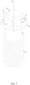
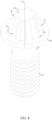
- the present invention comprises a fastener head 2, a shank 1, and an external threading 17.
- the fastener head 2 acts as the interface portion of the present invention that receives a torque force from an external torque tool.
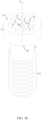
- the fastener head 2 comprises a rotation axis 3, a plurality of engagement walls 4, a first base 15, and a second base 16.
- Each of the plurality of engagement walls 4 interlock and grip the external torque tool to efficiently receive and transfer a torque force from the external torque tool to the shank 1.
- the plurality of engagement walls 4 is radially distributed about the rotation axis 3; wherein, the number within the plurality of engagement walls 4 is subject to change.
- each of the engagement walls comprises a first transversal line 6, a second transversal line 8, and a partially-circular portion 10.
- the first transversal line 6 and the second transversal line 8 make up the straight and flat portion for each of the plurality of engagement walls 4.
- the partially-circular portion 10 is a semi-circular line that acts as the interlocking feature for the each of the plurality of engagement walls 4 to prevent slippage and increase the amount of torque force the fastener head 2 may receive without damage and slippage.
- the curvature, size, and location of the partially-circular portion 10 is subject to change.
- the partially circular portion 10 may be different shape including, but not limited to, triangular, rectangular, or square shaped.
- a rounded profile is used to decrease the number of potential high stress points, thus decreasing potential points where the fastener head 2 might break or slip.
- the first transversal line 6 is terminally connected to the partially-circular portion 10.
- the second transversal line 8 is terminally connected to the partially-circular portion 10. It is preferred that the first transversal line 6 and the second transversal line 8 are colinearly aligned with each other and, therefore, are parallel to each other.
- the partially-circular portion 10 is configured such that a center 11 of the partially-circular portion 10 is oriented away from the rotation axis 3.
- the first base 15 and the second base 16 are positioned parallel and opposite to each other, across the plurality of engagement walls 4.
- first base 15 and the second base 16 are oriented perpendicular to each of the plurality of engagement walls 4. Resultantly, the plurality of engagement walls 4, the first base 15, and the second base 16 delineate a prism shape for the fastener head 2.
- the plurality of engagement walls 4 comprises an arbitrary engagement wall 12 and an adjacent engagement wall 13.
- the arbitrary engagement wall 12 is any feature within the plurality of engagement walls 4 and the adjacent engagement wall 13 is the feature directly next to the arbitrary engagement wall 12.
- the second transversal line 8 of the arbitrary engagement wall 12 is terminally connected to the first transversal line 6 of the adjacent engagement wall 13, opposite the partially-circular portion 10 of the adjacent engagement wall 13.
- the present invention may be designed to fit a variety of torque-tools. This is achieved by varying the number of engagement walls within the plurality of engagement walls 4 to compliment different types of torque-tools.
- the number within the plurality of engagement walls 4 corresponds to the number of sides of the fastener head 2. For instance, for a pentagon shaped fastener head 2, there are five engagement walls within the plurality of engagement walls 4. A hexagon shaped fastener head 2 requires six engagement walls within the plurality of engagement walls 4, an example is seen in FIG. 3 and FIG. 4 .
- the fastener head 2 is implemented as a square prism. For this, a quantity for the plurality of engagement walls 4 is four.
- the second transversal line 8 of the arbitrary sidewall is terminally connected to the first transversal line 6 of the adjacent sidewall at right angle as seen in FIG. 11 .
- the shank 1 is an elongated cylinder that makes up the body of the present invention.
- the length and diameter of the shank 1 is subject to change to meet the needs and preferences of the user.
- the external threading 17 is a helical structure used to convert between rotational and linear movement. Additionally, the external threading 17 engages a complimentary female threading of an external structure to secure and attach the present invention to the external structure.
- the shank 1 is concentrically and terminally mounted to the fastener head 2, similar to traditional screw designs. Specifically, the shank 1 is terminally and normally connected to the second base 16.
- the external threading 17 extends along the shank 1 and is laterally connected to the shank 1. The specific characteristics of the external threading 17, such as lead, pitch, and start, are subject to change to meet the needs and preferences of the user.
- the fastener head 2 may be implemented as a socket fastener.
- the fastener head 2 is outwardly extending from the cross section 5 of each of the plurality of engagement walls 4.
- the body of the fastener head 2 is external to the plurality of engagement walls 4 and the plurality of engagement walls 4 delineate a tool-receiving cavity 14.
- a torque-tool with a bit shank 1 is used and positioned within the tool-receiving cavity 14; a complimentary profile matching the profile of the plurality of engagement walls 4 is preferred, although, alternative profiles may be used as well.
- the plurality of engagement walls 4 tapers the tool-receiving cavity 14 from the first base 15 to the second base 16.
- the tapering feature allows for torque-tools of varying size to engage the fastener head 2, thus increasing the versatility of the present invention.
- an edge between each of the plurality of engagement walls 4 and the second base 16 may be chamfered or rounded.
- the present invention further comprises a security pin 18.
- the security pin 18 ensures that only specific torque-tools are capable of engaging the socket fastener embodiment of the present invention, thus restricting the tightening or extracting of the present invention to only personnel with the appropriate equipment.
- the security pin 18 is an elongated cylinder that length of the fastener head 2 from the first base 15 to the second base 16.
- the security pin 18 is concentrically positioned within the rotation axis 3 and is mounted within the tool-receiving cavity 14. Thus, to engage the present invention, a torque-tool with a complimentary cavity is required.
- the present invention may further comprise an annular flange 19 that acts similar to a washer to distribute the load of the present invention to the surface of the external structure that the present invention is attached to.
- the annular flange 19 is a disk with a central hole, wherein the central hole is sized to the outer diameter of the shank 1.
- the annular flange 19 is concentrically positioned within the rotation axis 3 and positioned adjacent to the fastener head 2. Additionally, the annular flange 19 is laterally connected to shank 1.
- the outer diameter, thickness, and design of the annular flange 19 is subject to change. When the present invention is tightened into an external structure, the annular flange 19 sits directly against the external surface of the external structure and prevents the fastener head 2 from being driven into the external surface.
- the fastener head 2 may be implemented as a standard screw head.
- the fastener head 2 is laterally delineated by the cross section 5 of each of the plurality of engagement walls 4.
- the body of the fastener head 2 is within the cross section 5 of the plurality of engagement walls 4 such that a torque-tool with a socket is required to engage the fastener head 2.
- the partially- circular portion for each of the plurality of engagement walls 4 is a cavity.
- the fastener head 2 tapers from the second base 16 to the first base 15 to allow a range of socket size to fit over and interlock with the fastener head 2 of the present invention, thus increasing the versatility of the present invention.
- an edge between each of the plurality of engagement walls 4 and the first base 15 may be chamfered or rounded.
- a security recess may be used.
- the security recess is a cavity that is positioned concentric with the rotation axis 3. Additionally, the security recess normally traverses into the fastener head 2 from the first base 15 to the second base 16.
- each of the plurality of engagement walls 4 may be implemented in a multitude of designs to create varying secure designs.
- a length 7 of the first transversal line 6 is equal to a length 9 of the second transversal line 8. This outlines a symmetrical design wherein the partially-circular portion 10 is centrally located and provides equal traction for tightening and loosening of the present invention.
- the length 7 of the first transversal line 6 is greater than the length 9 of the second transversal line 8 as seen in FIG. 2 .
- the partially-circular portion 10 is positioned offset from the center of the corresponding wall from the plurality of engagement walls 4. This ensures adequate torque force is transferred to the present invention in the clockwise rotation for tightening purposes.
- the present invention is implemented for extracting purposes.
- the length 7 of the first transversal line 6 is less than the length 9 of the second transversal line 8. This ensures adequate torque force is transferred to the present invention in the counter-clockwise rotation for extraction purposes.
Landscapes
- Engineering & Computer Science (AREA)
- General Engineering & Computer Science (AREA)
- Mechanical Engineering (AREA)
- Details Of Spanners, Wrenches, And Screw Drivers And Accessories (AREA)
- Connection Of Plates (AREA)
- Dowels (AREA)
- Slide Fasteners, Snap Fasteners, And Hook Fasteners (AREA)
Claims (11)
- Rutschsicheres Befestigungselement, umfassend:einen Schaft (1);einen Befestigungselementkopf (2);ein Außengewinde (17);wobei der Befestigungselementkopf (2) eine Drehachse (3) und eine Vielzahl von Eingriffswänden (4) umfasst;die Vielzahl von Eingriffswänden (4) radial um die Drehachse (3) verteilt sind;ein Querschnitt (5) für jede von der Vielzahl von Eingriffswänden (4) eine erste Querlinie (6), eine zweite Querlinie (8) und einen teilkreisförmigen Abschnitt (10) umfasst;die erste Querlinie (6) abschließend mit dem teilkreisförmigen Abschnitt (10) verbunden ist;die zweite Querlinie (8) abschließend mit dem teilkreisförmigen Abschnitt (10) verbunden ist, entgegengesetzt zu der ersten Querlinie (6);eine Mitte (11) des teilkreisförmigen Abschnitts (10) von der Drehachse (3) weg ausgerichtet ist;eine Länge (7) der ersten Querlinie (6) größer als oder kleiner als eine Länge (9) der zweiten Querlinie (8) ist;der Schaft (1) konzentrisch und abschließend an dem Befestigungselementkopf (2) montiert ist;das Außengewinde (17) sich entlang dem Schaft (1) erstreckt unddas Außengewinde (17) lateral mit dem Schaft (1) verbunden ist.
- Rutschsicheres Befestigungselement nach Anspruch 1, umfassend:der Befestigungselementkopf (2) umfasst weiterhin eine erste Basis (15) und eine zweite Basis (16);die erste Basis (15) und die zweite Basis (16) sind parallel und entgegengesetzt zueinander über die Vielzahl von Eingriffswänden (4) positioniert;die erste Basis (15) und die zweite Basis (16) sind senkrecht zu jeder von der Vielzahl von Eingriffswänden (4) ausgerichtet undder Schaft (1) ist abschließend mit der zweiten Basis (16) verbunden.
- Rutschsicheres Befestigungselement nach Anspruch 1, umfassend:die Vielzahl von Eingriffswänden (4) umfasst eine willkürliche Eingriffswand (12) und eine angrenzende Eingriffswand (13) unddie zweite Querlinie (8) der willkürlichen Eingriffswand (12) ist abschließend mit der ersten Querlinie (6) der angrenzenden Eingriffswand (13) verbunden, entgegengesetzt zu dem teilkreisförmigen Abschnitt (10) der angrenzenden Eingriffswand (13).
- Rutschsicheres Befestigungselement nach Anspruch 3, umfassend:die zweite Querlinie (8) der willkürlichen Eingriffswand (12) ist abschließend im rechten Winkel mit der ersten Querlinie (6) der angrenzenden Eingriffswand (13) verbunden;wobei eine Anzahl für die Vielzahl von Eingriffswänden (4) vier ist.
- Rutschsicheres Befestigungselement nach Anspruch 1, umfassend:wobei der Befestigungselementkopf (2) von dem Querschnitt jeder von der Vielzahl von Eingriffswänden (4) nach außen erweitert ist;die Vielzahl von Eingriffswänden (4) eine Werkzeugaufnahmeaussparung (14) abgrenzt;der Befestigungselementkopf (2) weiterhin eine erste Basis (15) und eine zweite Basis (16) umfasst;die erste Basis (15) und die zweite Basis (16) parallel und entgegengesetzt zueinander über die Vielzahl von Eingriffswänden (4) positioniert sind; undder Schaft (1) abschließend mit der zweiten Basis (16) verbunden ist.
- Rutschsicheres Befestigungselement nach Anspruch 5, wobei die Vielzahl von Eingriffswänden (4) die Werkzeugaufnahmeaussparung (14) von der ersten Basis (15) zu der zweiten Basis (16) verjüngt.
- Rutschsicheres Befestigungselement nach Anspruch 5, umfassend:einen Sicherungsstift (18);wobei der Sicherungsstift (18) konzentrisch mit der Drehachse (3) positioniert ist undder Sicherungsstift (18) innerhalb der Werkzeugaufnahmeaussparung (14) montiert ist.
- Rutschsicheres Befestigungselement nach Anspruch 1, wobei die erste Querlinie (6) und die zweite Querlinie (8) kolinear miteinander positioniert sind.
- Rutschsicheres Befestigungselement nach Anspruch 1, umfassend:einen ringförmigen Flansch (19);wobei der ringförmige Flansch (19) konzentrisch mit der Drehachse (3) positioniert ist;der ringförmige Flansch (19) angrenzend an den Befestigungselementkopf (2) positioniert ist undder ringförmige Flansch (19) lateral mit dem Schaft (1) verbunden ist.
- Rutschsicheres Befestigungselement nach Anspruch 1, umfassend:
der Befestigungselementkopf (2) ist durch den Querschnitt (5) jeder von der Vielzahl von Eingriffswänden (4) lateral abgegrenzt. - Rutschsicheres Befestigungselement nach Anspruch 1, umfassend:der Befestigungselementkopf (2) ist durch den Querschnitt (5) jeder von der Vielzahl von Eingriffswänden (4) lateral abgegrenzt;der Befestigungselementkopf (2) umfasst weiterhin eine erste Basis (15) und eine zweite Basis (16);die erste Basis (15) und die zweite Basis (16) sind parallel und entgegengesetzt zueinander über die Vielzahl von Eingriffswänden (4) positioniert;der Schaft (1) ist abschließend mit der zweiten Basis (16) verbunden undder Befestigungselementkopf (2) verjüngt sich von der zweiten Basis (16) zu der ersten Basis (15).
Priority Applications (1)
| Application Number | Priority Date | Filing Date | Title |
|---|---|---|---|
| EP24200250.9A EP4455495A3 (de) | 2018-03-02 | 2019-03-04 | Rutschhemmendes befestigungselement |
Applications Claiming Priority (3)
| Application Number | Priority Date | Filing Date | Title |
|---|---|---|---|
| US201862637692P | 2018-03-02 | 2018-03-02 | |
| US201862756938P | 2018-11-07 | 2018-11-07 | |
| PCT/IB2019/051742 WO2019167032A1 (en) | 2018-03-02 | 2019-03-04 | Anti-slippage fastener |
Related Child Applications (2)
| Application Number | Title | Priority Date | Filing Date |
|---|---|---|---|
| EP24200250.9A Division EP4455495A3 (de) | 2018-03-02 | 2019-03-04 | Rutschhemmendes befestigungselement |
| EP24200250.9A Division-Into EP4455495A3 (de) | 2018-03-02 | 2019-03-04 | Rutschhemmendes befestigungselement |
Publications (4)
| Publication Number | Publication Date |
|---|---|
| EP3759364A1 EP3759364A1 (de) | 2021-01-06 |
| EP3759364A4 EP3759364A4 (de) | 2021-12-01 |
| EP3759364B1 true EP3759364B1 (de) | 2024-11-06 |
| EP3759364C0 EP3759364C0 (de) | 2024-11-06 |
Family
ID=67805690
Family Applications (2)
| Application Number | Title | Priority Date | Filing Date |
|---|---|---|---|
| EP19760616.3A Active EP3759364B1 (de) | 2018-03-02 | 2019-03-04 | Rutschhemmende befestigungsvorrichtung |
| EP24200250.9A Pending EP4455495A3 (de) | 2018-03-02 | 2019-03-04 | Rutschhemmendes befestigungselement |
Family Applications After (1)
| Application Number | Title | Priority Date | Filing Date |
|---|---|---|---|
| EP24200250.9A Pending EP4455495A3 (de) | 2018-03-02 | 2019-03-04 | Rutschhemmendes befestigungselement |
Country Status (7)
| Country | Link |
|---|---|
| US (1) | US12018708B2 (de) |
| EP (2) | EP3759364B1 (de) |
| CN (2) | CN111971480B (de) |
| AU (2) | AU2019226491B2 (de) |
| CA (1) | CA3096421A1 (de) |
| TW (1) | TWI812676B (de) |
| WO (1) | WO2019167032A1 (de) |
Families Citing this family (18)
| Publication number | Priority date | Publication date | Assignee | Title |
|---|---|---|---|---|
| US11154969B2 (en) | 2016-04-27 | 2021-10-26 | Grip Holdings Llc | Fastener extractor device |
| US11234899B2 (en) | 2017-05-11 | 2022-02-01 | Scalpal Llc | Grasping facilitators and uses thereof and kits involving the same |
| US11897099B2 (en) | 2018-09-19 | 2024-02-13 | Grip Holdings Llc | Fastener extractor and dislodging tool apparatus |
| US12403574B2 (en) | 2016-04-27 | 2025-09-02 | Grip Holdings Llc | Fastener extractor device |
| US11590637B2 (en) | 2017-04-27 | 2023-02-28 | Grip Holdings Llc | Methods and apparatuses for extracting and dislodging fasteners |
| US12023786B2 (en) | 2017-02-15 | 2024-07-02 | Grip Holdings Llc | Multi-directional driver bit |
| US11602828B2 (en) | 2019-07-30 | 2023-03-14 | Grip Holdings Llc | Multi-grip screw apparatus |
| US12434360B2 (en) | 2017-03-23 | 2025-10-07 | Grip Holdings Llc | Advanced holding apparatus |
| US11701757B2 (en) | 2018-09-19 | 2023-07-18 | Grip Holdings Llc | Anti-slip fastener remover tool |
| US11969864B2 (en) | 2017-05-11 | 2024-04-30 | Scalpal Llc | Multi-tier torque enhancer driver and/or receiver and method of using same |
| USD966063S1 (en) | 2018-03-07 | 2022-10-11 | Grip Holdings Llc | Socket |
| US12337449B2 (en) | 2017-07-14 | 2025-06-24 | Grip Holdings Llc | Foreign object removal socket adapter |
| US11161234B2 (en) | 2018-03-15 | 2021-11-02 | Grip Holdings Llc | Tool holding apparatus |
| US12296440B2 (en) | 2019-04-12 | 2025-05-13 | Grip Holdings Llc | Anti-slip multidirectional fastener remover tool |
| US11759918B2 (en) | 2019-05-09 | 2023-09-19 | Grip Holdings Llc | Anti-slip torque tool with integrated engagement features |
| USD1042059S1 (en) | 2022-02-25 | 2024-09-17 | Grip Holdings Llc | Percussion drive |
| USD1026602S1 (en) | 2022-03-17 | 2024-05-14 | Grip Holdings Llc | Selectable twist tool |
| KR20250141169A (ko) * | 2023-01-31 | 2025-09-26 | 그립 홀딩스 엘엘씨 | 진보된 홀딩 장치 |
Family Cites Families (20)
| Publication number | Priority date | Publication date | Assignee | Title |
|---|---|---|---|---|
| US3908489A (en) * | 1973-11-30 | 1975-09-30 | Yamamoto Byora Co Ltd | Fastener driver |
| US3885480A (en) * | 1973-12-07 | 1975-05-27 | Res Eng & Mfg | Torque-transmitting arrangement for fasteners and the like |
| US4187892A (en) * | 1974-09-12 | 1980-02-12 | Phillips Screw Company | Recessed screw heads and drivers |
| US4607547A (en) * | 1985-02-06 | 1986-08-26 | Martus Donald G | Stripped hex head drive socket |
| DE4321325A1 (de) * | 1993-06-26 | 1995-01-05 | Wera Werk Gmbh & Co | Eindrehbefestigungselement |
| DE9403220U1 (de) * | 1994-02-26 | 1994-04-21 | Pauli + Sohn GmbH, 51545 Waldbröl | Klemmhalter |
| DE10321284A1 (de) * | 2003-05-13 | 2004-12-16 | Richard Bergner Verbindungstechnik Gmbh & Co. Kg | Schraube mit einem gelappten Mehrkantkopf und Werkzeug zum Betätigen einer Schraube mit einem gelappten Mehrkantkopf |
| US8105367B2 (en) * | 2003-09-29 | 2012-01-31 | Smith & Nephew, Inc. | Bone plate and bone plate assemblies including polyaxial fasteners |
| CN1862036A (zh) * | 2005-05-10 | 2006-11-15 | 宽仕工业股份有限公司 | 螺丝、冲具与起子头 |
| US7225710B2 (en) * | 2005-05-27 | 2007-06-05 | Synthes Gmbh | Combination driver and combination fastener |
| US20090220321A1 (en) * | 2008-02-28 | 2009-09-03 | Sakamura Machine Co., Ltd. | Fastening metal fitting |
| EP2747944B1 (de) * | 2011-08-25 | 2023-04-19 | Infastech Intellectual Properties Pte. Ltd. | Konischer wälzkolbentreiber und befestigungselement |
| DE102013012577A1 (de) * | 2013-07-30 | 2015-02-05 | Steven Keiner | Verbindungselement eines Verbindungssystems, Werkzeug zum Verbinden, Lösen und Prüfen des Verbindungselementes, Verfahren zum Versehen eines Verbindungssystems mit einer Verschlussversiegelung |
| DE102013021238A1 (de) * | 2013-12-14 | 2015-06-18 | Daimler Ag | Schraubelement mit einem Werkzeugangriff |
| US9651078B2 (en) * | 2014-09-23 | 2017-05-16 | Jose Ricardo Santiago-Anadon | Torque limiting fastener |
| US10788077B2 (en) | 2015-03-19 | 2020-09-29 | Acument Intellectual Properties, Llc | Drive system with full surface drive contact |
| WO2017072182A1 (de) * | 2015-10-30 | 2017-05-04 | Abc Umformtechnik Gmbh & Co. Kg | Diebstahlgesichertes schraubteil zur befestigung einer felge an einem kraftfahrzeug |
| KR20170130838A (ko) * | 2016-05-19 | 2017-11-29 | 주식회사 대한볼트 | 임의 도난방지 기능을 가지는 육각홈붙이 볼트 및 이의 제조방법 |
| AU2017271372A1 (en) * | 2016-05-27 | 2018-12-13 | Grip Holdings Llc | Anti-slip wrench-type tool |
| DE102016119234A1 (de) * | 2016-10-10 | 2018-04-12 | Syntellix Ag | Schraubenantrieb mit integrierter Drehmomentsicherung |
-
2019
- 2019-03-04 US US17/047,628 patent/US12018708B2/en active Active
- 2019-03-04 CN CN201980025131.6A patent/CN111971480B/zh active Active
- 2019-03-04 TW TW108107030A patent/TWI812676B/zh active
- 2019-03-04 EP EP19760616.3A patent/EP3759364B1/de active Active
- 2019-03-04 CN CN202311479149.8A patent/CN117307580A/zh active Pending
- 2019-03-04 EP EP24200250.9A patent/EP4455495A3/de active Pending
- 2019-03-04 AU AU2019226491A patent/AU2019226491B2/en active Active
- 2019-03-04 CA CA3096421A patent/CA3096421A1/en active Pending
- 2019-03-04 WO PCT/IB2019/051742 patent/WO2019167032A1/en not_active Ceased
-
2024
- 2024-07-17 AU AU2024204899A patent/AU2024204899A1/en active Pending
Also Published As
| Publication number | Publication date |
|---|---|
| AU2024204899A1 (en) | 2024-08-01 |
| EP4455495A3 (de) | 2025-02-19 |
| US12018708B2 (en) | 2024-06-25 |
| AU2019226491A1 (en) | 2020-10-15 |
| US20210148395A1 (en) | 2021-05-20 |
| WO2019167032A1 (en) | 2019-09-06 |
| EP3759364A4 (de) | 2021-12-01 |
| CA3096421A1 (en) | 2019-09-06 |
| TW201938335A (zh) | 2019-10-01 |
| EP3759364A1 (de) | 2021-01-06 |
| CN111971480B (zh) | 2023-11-24 |
| TWI812676B (zh) | 2023-08-21 |
| CN117307580A (zh) | 2023-12-29 |
| EP4455495A2 (de) | 2024-10-30 |
| CN111971480A (zh) | 2020-11-20 |
| EP3759364C0 (de) | 2024-11-06 |
| AU2019226491B2 (en) | 2024-04-18 |
Similar Documents
| Publication | Publication Date | Title |
|---|---|---|
| EP3759364B1 (de) | Rutschhemmende befestigungsvorrichtung | |
| US10780556B2 (en) | Anti-slip, multidirectional driver bit | |
| US10081094B2 (en) | Multi-grip socket bit | |
| US10967488B2 (en) | Advanced holding apparatus | |
| AU2017404582B2 (en) | Multi-grip socket bit | |
| US11045925B2 (en) | Anti-slip fastener remover tool | |
| EP4094892B1 (de) | Fortschrittliche haltevorrichtung | |
| EP3990221B1 (de) | Fortschrittliche haltevorrichtung | |
| AU2019424113B2 (en) | Anti-slip fastener remover tool | |
| US10882162B2 (en) | Spherical anti-slip fastener remover | |
| US11364602B2 (en) | Multi-directional driver bit | |
| US12023786B2 (en) | Multi-directional driver bit | |
| WO2018150360A1 (en) | Multi-directional driver bit | |
| US20210220977A1 (en) | Advanced Holding Apparatus | |
| US20240309901A1 (en) | Anti-Slippage Fastener | |
| WO2023230168A1 (en) | Multi-directional driver bit |
Legal Events
| Date | Code | Title | Description |
|---|---|---|---|
| STAA | Information on the status of an ep patent application or granted ep patent |
Free format text: STATUS: THE INTERNATIONAL PUBLICATION HAS BEEN MADE |
|
| PUAI | Public reference made under article 153(3) epc to a published international application that has entered the european phase |
Free format text: ORIGINAL CODE: 0009012 |
|
| STAA | Information on the status of an ep patent application or granted ep patent |
Free format text: STATUS: REQUEST FOR EXAMINATION WAS MADE |
|
| 17P | Request for examination filed |
Effective date: 20200925 |
|
| AK | Designated contracting states |
Kind code of ref document: A1 Designated state(s): AL AT BE BG CH CY CZ DE DK EE ES FI FR GB GR HR HU IE IS IT LI LT LU LV MC MK MT NL NO PL PT RO RS SE SI SK SM TR |
|
| AX | Request for extension of the european patent |
Extension state: BA ME |
|
| DAV | Request for validation of the european patent (deleted) | ||
| DAX | Request for extension of the european patent (deleted) | ||
| A4 | Supplementary search report drawn up and despatched |
Effective date: 20211103 |
|
| RIC1 | Information provided on ipc code assigned before grant |
Ipc: F16B 23/00 20060101AFI20211027BHEP |
|
| GRAP | Despatch of communication of intention to grant a patent |
Free format text: ORIGINAL CODE: EPIDOSNIGR1 |
|
| STAA | Information on the status of an ep patent application or granted ep patent |
Free format text: STATUS: GRANT OF PATENT IS INTENDED |
|
| INTG | Intention to grant announced |
Effective date: 20240531 |
|
| GRAS | Grant fee paid |
Free format text: ORIGINAL CODE: EPIDOSNIGR3 |
|
| GRAA | (expected) grant |
Free format text: ORIGINAL CODE: 0009210 |
|
| STAA | Information on the status of an ep patent application or granted ep patent |
Free format text: STATUS: THE PATENT HAS BEEN GRANTED |
|
| AK | Designated contracting states |
Kind code of ref document: B1 Designated state(s): AL AT BE BG CH CY CZ DE DK EE ES FI FR GB GR HR HU IE IS IT LI LT LU LV MC MK MT NL NO PL PT RO RS SE SI SK SM TR |
|
| REG | Reference to a national code |
Ref country code: GB Ref legal event code: FG4D |
|
| REG | Reference to a national code |
Ref country code: CH Ref legal event code: EP |
|
| REG | Reference to a national code |
Ref country code: DE Ref legal event code: R096 Ref document number: 602019061528 Country of ref document: DE |
|
| REG | Reference to a national code |
Ref country code: IE Ref legal event code: FG4D |
|
| U01 | Request for unitary effect filed |
Effective date: 20241204 |
|
| U07 | Unitary effect registered |
Designated state(s): AT BE BG DE DK EE FI FR IT LT LU LV MT NL PT RO SE SI Effective date: 20241212 |
|
| U20 | Renewal fee for the european patent with unitary effect paid |
Year of fee payment: 7 Effective date: 20250218 |
|
| PG25 | Lapsed in a contracting state [announced via postgrant information from national office to epo] |
Ref country code: IS Free format text: LAPSE BECAUSE OF FAILURE TO SUBMIT A TRANSLATION OF THE DESCRIPTION OR TO PAY THE FEE WITHIN THE PRESCRIBED TIME-LIMIT Effective date: 20250306 Ref country code: HR Free format text: LAPSE BECAUSE OF FAILURE TO SUBMIT A TRANSLATION OF THE DESCRIPTION OR TO PAY THE FEE WITHIN THE PRESCRIBED TIME-LIMIT Effective date: 20241106 |
|
| PG25 | Lapsed in a contracting state [announced via postgrant information from national office to epo] |
Ref country code: ES Free format text: LAPSE BECAUSE OF FAILURE TO SUBMIT A TRANSLATION OF THE DESCRIPTION OR TO PAY THE FEE WITHIN THE PRESCRIBED TIME-LIMIT Effective date: 20241106 |
|
| PG25 | Lapsed in a contracting state [announced via postgrant information from national office to epo] |
Ref country code: NO Free format text: LAPSE BECAUSE OF FAILURE TO SUBMIT A TRANSLATION OF THE DESCRIPTION OR TO PAY THE FEE WITHIN THE PRESCRIBED TIME-LIMIT Effective date: 20250206 |
|
| PG25 | Lapsed in a contracting state [announced via postgrant information from national office to epo] |
Ref country code: GR Free format text: LAPSE BECAUSE OF FAILURE TO SUBMIT A TRANSLATION OF THE DESCRIPTION OR TO PAY THE FEE WITHIN THE PRESCRIBED TIME-LIMIT Effective date: 20250207 |
|
| PG25 | Lapsed in a contracting state [announced via postgrant information from national office to epo] |
Ref country code: PL Free format text: LAPSE BECAUSE OF FAILURE TO SUBMIT A TRANSLATION OF THE DESCRIPTION OR TO PAY THE FEE WITHIN THE PRESCRIBED TIME-LIMIT Effective date: 20241106 |
|
| PGFP | Annual fee paid to national office [announced via postgrant information from national office to epo] |
Ref country code: GB Payment date: 20250218 Year of fee payment: 7 |
|
| PG25 | Lapsed in a contracting state [announced via postgrant information from national office to epo] |
Ref country code: RS Free format text: LAPSE BECAUSE OF FAILURE TO SUBMIT A TRANSLATION OF THE DESCRIPTION OR TO PAY THE FEE WITHIN THE PRESCRIBED TIME-LIMIT Effective date: 20250206 |
|
| PG25 | Lapsed in a contracting state [announced via postgrant information from national office to epo] |
Ref country code: SM Free format text: LAPSE BECAUSE OF FAILURE TO SUBMIT A TRANSLATION OF THE DESCRIPTION OR TO PAY THE FEE WITHIN THE PRESCRIBED TIME-LIMIT Effective date: 20241106 |
|
| PGFP | Annual fee paid to national office [announced via postgrant information from national office to epo] |
Ref country code: CH Payment date: 20250402 Year of fee payment: 7 |
|
| PG25 | Lapsed in a contracting state [announced via postgrant information from national office to epo] |
Ref country code: SK Free format text: LAPSE BECAUSE OF FAILURE TO SUBMIT A TRANSLATION OF THE DESCRIPTION OR TO PAY THE FEE WITHIN THE PRESCRIBED TIME-LIMIT Effective date: 20241106 |
|
| PG25 | Lapsed in a contracting state [announced via postgrant information from national office to epo] |
Ref country code: CZ Free format text: LAPSE BECAUSE OF FAILURE TO SUBMIT A TRANSLATION OF THE DESCRIPTION OR TO PAY THE FEE WITHIN THE PRESCRIBED TIME-LIMIT Effective date: 20241106 |
|
| PLBE | No opposition filed within time limit |
Free format text: ORIGINAL CODE: 0009261 |
|
| STAA | Information on the status of an ep patent application or granted ep patent |
Free format text: STATUS: NO OPPOSITION FILED WITHIN TIME LIMIT |
|
| PG25 | Lapsed in a contracting state [announced via postgrant information from national office to epo] |
Ref country code: MC Free format text: LAPSE BECAUSE OF FAILURE TO SUBMIT A TRANSLATION OF THE DESCRIPTION OR TO PAY THE FEE WITHIN THE PRESCRIBED TIME-LIMIT Effective date: 20241106 |
|
| 26N | No opposition filed |
Effective date: 20250807 |