EP3759028B1 - A corner element for a cage-like structure and a cage-like structure provided with such corner elements - Google Patents
A corner element for a cage-like structure and a cage-like structure provided with such corner elements Download PDFInfo
- Publication number
- EP3759028B1 EP3759028B1 EP19760885.4A EP19760885A EP3759028B1 EP 3759028 B1 EP3759028 B1 EP 3759028B1 EP 19760885 A EP19760885 A EP 19760885A EP 3759028 B1 EP3759028 B1 EP 3759028B1
- Authority
- EP
- European Patent Office
- Prior art keywords
- board
- bottom portion
- wall portions
- wall
- members
- Prior art date
- Legal status (The legal status is an assumption and is not a legal conclusion. Google has not performed a legal analysis and makes no representation as to the accuracy of the status listed.)
- Active
Links
Images


Classifications
-
- B—PERFORMING OPERATIONS; TRANSPORTING
- B65—CONVEYING; PACKING; STORING; HANDLING THIN OR FILAMENTARY MATERIAL
- B65D—CONTAINERS FOR STORAGE OR TRANSPORT OF ARTICLES OR MATERIALS, e.g. BAGS, BARRELS, BOTTLES, BOXES, CANS, CARTONS, CRATES, DRUMS, JARS, TANKS, HOPPERS, FORWARDING CONTAINERS; ACCESSORIES, CLOSURES, OR FITTINGS THEREFOR; PACKAGING ELEMENTS; PACKAGES
- B65D9/00—Containers having bodies formed by interconnecting or uniting two or more rigid, or substantially rigid, components made wholly or mainly of wood or substitutes therefor
- B65D9/32—Details of wooden walls; Connections between walls
- B65D9/34—Joints; Local reinforcements
-
- B—PERFORMING OPERATIONS; TRANSPORTING
- B65—CONVEYING; PACKING; STORING; HANDLING THIN OR FILAMENTARY MATERIAL
- B65D—CONTAINERS FOR STORAGE OR TRANSPORT OF ARTICLES OR MATERIALS, e.g. BAGS, BARRELS, BOTTLES, BOXES, CANS, CARTONS, CRATES, DRUMS, JARS, TANKS, HOPPERS, FORWARDING CONTAINERS; ACCESSORIES, CLOSURES, OR FITTINGS THEREFOR; PACKAGING ELEMENTS; PACKAGES
- B65D19/00—Pallets or like platforms, with or without side walls, for supporting loads to be lifted or lowered
- B65D19/38—Details or accessories
- B65D19/385—Frames, corner posts or pallet converters, e.g. for facilitating stacking of charged pallets
-
- B—PERFORMING OPERATIONS; TRANSPORTING
- B65—CONVEYING; PACKING; STORING; HANDLING THIN OR FILAMENTARY MATERIAL
- B65D—CONTAINERS FOR STORAGE OR TRANSPORT OF ARTICLES OR MATERIALS, e.g. BAGS, BARRELS, BOTTLES, BOXES, CANS, CARTONS, CRATES, DRUMS, JARS, TANKS, HOPPERS, FORWARDING CONTAINERS; ACCESSORIES, CLOSURES, OR FITTINGS THEREFOR; PACKAGING ELEMENTS; PACKAGES
- B65D19/00—Pallets or like platforms, with or without side walls, for supporting loads to be lifted or lowered
- B65D19/38—Details or accessories
-
- B—PERFORMING OPERATIONS; TRANSPORTING
- B65—CONVEYING; PACKING; STORING; HANDLING THIN OR FILAMENTARY MATERIAL
- B65D—CONTAINERS FOR STORAGE OR TRANSPORT OF ARTICLES OR MATERIALS, e.g. BAGS, BARRELS, BOTTLES, BOXES, CANS, CARTONS, CRATES, DRUMS, JARS, TANKS, HOPPERS, FORWARDING CONTAINERS; ACCESSORIES, CLOSURES, OR FITTINGS THEREFOR; PACKAGING ELEMENTS; PACKAGES
- B65D19/00—Pallets or like platforms, with or without side walls, for supporting loads to be lifted or lowered
- B65D19/02—Rigid pallets with side walls, e.g. box pallets
- B65D19/06—Rigid pallets with side walls, e.g. box pallets with bodies formed by uniting or interconnecting two or more components
- B65D19/14—Rigid pallets with side walls, e.g. box pallets with bodies formed by uniting or interconnecting two or more components made wholly or mainly of wood
- B65D19/16—Collapsible pallets
-
- B—PERFORMING OPERATIONS; TRANSPORTING
- B65—CONVEYING; PACKING; STORING; HANDLING THIN OR FILAMENTARY MATERIAL
- B65D—CONTAINERS FOR STORAGE OR TRANSPORT OF ARTICLES OR MATERIALS, e.g. BAGS, BARRELS, BOTTLES, BOXES, CANS, CARTONS, CRATES, DRUMS, JARS, TANKS, HOPPERS, FORWARDING CONTAINERS; ACCESSORIES, CLOSURES, OR FITTINGS THEREFOR; PACKAGING ELEMENTS; PACKAGES
- B65D9/00—Containers having bodies formed by interconnecting or uniting two or more rigid, or substantially rigid, components made wholly or mainly of wood or substitutes therefor
- B65D9/12—Containers having bodies formed by interconnecting or uniting two or more rigid, or substantially rigid, components made wholly or mainly of wood or substitutes therefor collapsible, e.g. with all parts detachable
- B65D9/22—Fastening devices for holding collapsible containers in erected state, e.g. integral with container walls
- B65D9/24—Fastening devices for holding collapsible containers in erected state, e.g. integral with container walls separate from container walls
-
- B—PERFORMING OPERATIONS; TRANSPORTING
- B65—CONVEYING; PACKING; STORING; HANDLING THIN OR FILAMENTARY MATERIAL
- B65D—CONTAINERS FOR STORAGE OR TRANSPORT OF ARTICLES OR MATERIALS, e.g. BAGS, BARRELS, BOTTLES, BOXES, CANS, CARTONS, CRATES, DRUMS, JARS, TANKS, HOPPERS, FORWARDING CONTAINERS; ACCESSORIES, CLOSURES, OR FITTINGS THEREFOR; PACKAGING ELEMENTS; PACKAGES
- B65D2519/00—Pallets or like platforms, with or without side walls, for supporting loads to be lifted or lowered
- B65D2519/00004—Details relating to pallets
- B65D2519/00009—Materials
- B65D2519/00014—Materials for the load supporting surface
- B65D2519/00029—Wood
-
- B—PERFORMING OPERATIONS; TRANSPORTING
- B65—CONVEYING; PACKING; STORING; HANDLING THIN OR FILAMENTARY MATERIAL
- B65D—CONTAINERS FOR STORAGE OR TRANSPORT OF ARTICLES OR MATERIALS, e.g. BAGS, BARRELS, BOTTLES, BOXES, CANS, CARTONS, CRATES, DRUMS, JARS, TANKS, HOPPERS, FORWARDING CONTAINERS; ACCESSORIES, CLOSURES, OR FITTINGS THEREFOR; PACKAGING ELEMENTS; PACKAGES
- B65D2519/00—Pallets or like platforms, with or without side walls, for supporting loads to be lifted or lowered
- B65D2519/00004—Details relating to pallets
- B65D2519/00009—Materials
- B65D2519/00049—Materials for the base surface
- B65D2519/00064—Wood
-
- B—PERFORMING OPERATIONS; TRANSPORTING
- B65—CONVEYING; PACKING; STORING; HANDLING THIN OR FILAMENTARY MATERIAL
- B65D—CONTAINERS FOR STORAGE OR TRANSPORT OF ARTICLES OR MATERIALS, e.g. BAGS, BARRELS, BOTTLES, BOXES, CANS, CARTONS, CRATES, DRUMS, JARS, TANKS, HOPPERS, FORWARDING CONTAINERS; ACCESSORIES, CLOSURES, OR FITTINGS THEREFOR; PACKAGING ELEMENTS; PACKAGES
- B65D2519/00—Pallets or like platforms, with or without side walls, for supporting loads to be lifted or lowered
- B65D2519/00004—Details relating to pallets
- B65D2519/00009—Materials
- B65D2519/00084—Materials for the non-integral separating spacer
- B65D2519/00099—Wood
-
- B—PERFORMING OPERATIONS; TRANSPORTING
- B65—CONVEYING; PACKING; STORING; HANDLING THIN OR FILAMENTARY MATERIAL
- B65D—CONTAINERS FOR STORAGE OR TRANSPORT OF ARTICLES OR MATERIALS, e.g. BAGS, BARRELS, BOTTLES, BOXES, CANS, CARTONS, CRATES, DRUMS, JARS, TANKS, HOPPERS, FORWARDING CONTAINERS; ACCESSORIES, CLOSURES, OR FITTINGS THEREFOR; PACKAGING ELEMENTS; PACKAGES
- B65D2519/00—Pallets or like platforms, with or without side walls, for supporting loads to be lifted or lowered
- B65D2519/00004—Details relating to pallets
- B65D2519/00009—Materials
- B65D2519/00119—Materials for the construction of the reinforcements
- B65D2519/00134—Wood
-
- B—PERFORMING OPERATIONS; TRANSPORTING
- B65—CONVEYING; PACKING; STORING; HANDLING THIN OR FILAMENTARY MATERIAL
- B65D—CONTAINERS FOR STORAGE OR TRANSPORT OF ARTICLES OR MATERIALS, e.g. BAGS, BARRELS, BOTTLES, BOXES, CANS, CARTONS, CRATES, DRUMS, JARS, TANKS, HOPPERS, FORWARDING CONTAINERS; ACCESSORIES, CLOSURES, OR FITTINGS THEREFOR; PACKAGING ELEMENTS; PACKAGES
- B65D2519/00—Pallets or like platforms, with or without side walls, for supporting loads to be lifted or lowered
- B65D2519/00004—Details relating to pallets
- B65D2519/00009—Materials
- B65D2519/00154—Materials for the side walls
- B65D2519/00169—Wood
-
- B—PERFORMING OPERATIONS; TRANSPORTING
- B65—CONVEYING; PACKING; STORING; HANDLING THIN OR FILAMENTARY MATERIAL
- B65D—CONTAINERS FOR STORAGE OR TRANSPORT OF ARTICLES OR MATERIALS, e.g. BAGS, BARRELS, BOTTLES, BOXES, CANS, CARTONS, CRATES, DRUMS, JARS, TANKS, HOPPERS, FORWARDING CONTAINERS; ACCESSORIES, CLOSURES, OR FITTINGS THEREFOR; PACKAGING ELEMENTS; PACKAGES
- B65D2519/00—Pallets or like platforms, with or without side walls, for supporting loads to be lifted or lowered
- B65D2519/00004—Details relating to pallets
- B65D2519/00258—Overall construction
- B65D2519/00263—Overall construction of the pallet
- B65D2519/00273—Overall construction of the pallet made of more than one piece
-
- B—PERFORMING OPERATIONS; TRANSPORTING
- B65—CONVEYING; PACKING; STORING; HANDLING THIN OR FILAMENTARY MATERIAL
- B65D—CONTAINERS FOR STORAGE OR TRANSPORT OF ARTICLES OR MATERIALS, e.g. BAGS, BARRELS, BOTTLES, BOXES, CANS, CARTONS, CRATES, DRUMS, JARS, TANKS, HOPPERS, FORWARDING CONTAINERS; ACCESSORIES, CLOSURES, OR FITTINGS THEREFOR; PACKAGING ELEMENTS; PACKAGES
- B65D2519/00—Pallets or like platforms, with or without side walls, for supporting loads to be lifted or lowered
- B65D2519/00004—Details relating to pallets
- B65D2519/00258—Overall construction
- B65D2519/00283—Overall construction of the load supporting surface
- B65D2519/00293—Overall construction of the load supporting surface made of more than one piece
-
- B—PERFORMING OPERATIONS; TRANSPORTING
- B65—CONVEYING; PACKING; STORING; HANDLING THIN OR FILAMENTARY MATERIAL
- B65D—CONTAINERS FOR STORAGE OR TRANSPORT OF ARTICLES OR MATERIALS, e.g. BAGS, BARRELS, BOTTLES, BOXES, CANS, CARTONS, CRATES, DRUMS, JARS, TANKS, HOPPERS, FORWARDING CONTAINERS; ACCESSORIES, CLOSURES, OR FITTINGS THEREFOR; PACKAGING ELEMENTS; PACKAGES
- B65D2519/00—Pallets or like platforms, with or without side walls, for supporting loads to be lifted or lowered
- B65D2519/00004—Details relating to pallets
- B65D2519/00258—Overall construction
- B65D2519/00313—Overall construction of the base surface
- B65D2519/00323—Overall construction of the base surface made of more than one piece
-
- B—PERFORMING OPERATIONS; TRANSPORTING
- B65—CONVEYING; PACKING; STORING; HANDLING THIN OR FILAMENTARY MATERIAL
- B65D—CONTAINERS FOR STORAGE OR TRANSPORT OF ARTICLES OR MATERIALS, e.g. BAGS, BARRELS, BOTTLES, BOXES, CANS, CARTONS, CRATES, DRUMS, JARS, TANKS, HOPPERS, FORWARDING CONTAINERS; ACCESSORIES, CLOSURES, OR FITTINGS THEREFOR; PACKAGING ELEMENTS; PACKAGES
- B65D2519/00—Pallets or like platforms, with or without side walls, for supporting loads to be lifted or lowered
- B65D2519/00004—Details relating to pallets
- B65D2519/00258—Overall construction
- B65D2519/00313—Overall construction of the base surface
- B65D2519/00328—Overall construction of the base surface shape of the contact surface of the base
- B65D2519/00333—Overall construction of the base surface shape of the contact surface of the base contact surface having a stringer-like shape
-
- B—PERFORMING OPERATIONS; TRANSPORTING
- B65—CONVEYING; PACKING; STORING; HANDLING THIN OR FILAMENTARY MATERIAL
- B65D—CONTAINERS FOR STORAGE OR TRANSPORT OF ARTICLES OR MATERIALS, e.g. BAGS, BARRELS, BOTTLES, BOXES, CANS, CARTONS, CRATES, DRUMS, JARS, TANKS, HOPPERS, FORWARDING CONTAINERS; ACCESSORIES, CLOSURES, OR FITTINGS THEREFOR; PACKAGING ELEMENTS; PACKAGES
- B65D2519/00—Pallets or like platforms, with or without side walls, for supporting loads to be lifted or lowered
- B65D2519/00004—Details relating to pallets
- B65D2519/00258—Overall construction
- B65D2519/00398—Overall construction reinforcements
- B65D2519/00432—Non-integral, e.g. inserts
- B65D2519/00452—Non-integral, e.g. inserts on the walls
-
- B—PERFORMING OPERATIONS; TRANSPORTING
- B65—CONVEYING; PACKING; STORING; HANDLING THIN OR FILAMENTARY MATERIAL
- B65D—CONTAINERS FOR STORAGE OR TRANSPORT OF ARTICLES OR MATERIALS, e.g. BAGS, BARRELS, BOTTLES, BOXES, CANS, CARTONS, CRATES, DRUMS, JARS, TANKS, HOPPERS, FORWARDING CONTAINERS; ACCESSORIES, CLOSURES, OR FITTINGS THEREFOR; PACKAGING ELEMENTS; PACKAGES
- B65D2519/00—Pallets or like platforms, with or without side walls, for supporting loads to be lifted or lowered
- B65D2519/00004—Details relating to pallets
- B65D2519/00258—Overall construction
- B65D2519/00492—Overall construction of the side walls
- B65D2519/00502—Overall construction of the side walls whereby at least one side wall is made of two or more pieces
-
- B—PERFORMING OPERATIONS; TRANSPORTING
- B65—CONVEYING; PACKING; STORING; HANDLING THIN OR FILAMENTARY MATERIAL
- B65D—CONTAINERS FOR STORAGE OR TRANSPORT OF ARTICLES OR MATERIALS, e.g. BAGS, BARRELS, BOTTLES, BOXES, CANS, CARTONS, CRATES, DRUMS, JARS, TANKS, HOPPERS, FORWARDING CONTAINERS; ACCESSORIES, CLOSURES, OR FITTINGS THEREFOR; PACKAGING ELEMENTS; PACKAGES
- B65D2519/00—Pallets or like platforms, with or without side walls, for supporting loads to be lifted or lowered
- B65D2519/00004—Details relating to pallets
- B65D2519/00547—Connections
- B65D2519/00577—Connections structures connecting side walls, including corner posts, to each other
- B65D2519/00582—Connections structures connecting side walls, including corner posts, to each other structures intended to be disassembled, i.e. collapsible or dismountable
- B65D2519/00611—Connections structures connecting side walls, including corner posts, to each other structures intended to be disassembled, i.e. collapsible or dismountable side walls maintained connected to each other by means of auxiliary locking elements, e.g. spring loaded locking pins
-
- B—PERFORMING OPERATIONS; TRANSPORTING
- B65—CONVEYING; PACKING; STORING; HANDLING THIN OR FILAMENTARY MATERIAL
- B65D—CONTAINERS FOR STORAGE OR TRANSPORT OF ARTICLES OR MATERIALS, e.g. BAGS, BARRELS, BOTTLES, BOXES, CANS, CARTONS, CRATES, DRUMS, JARS, TANKS, HOPPERS, FORWARDING CONTAINERS; ACCESSORIES, CLOSURES, OR FITTINGS THEREFOR; PACKAGING ELEMENTS; PACKAGES
- B65D2519/00—Pallets or like platforms, with or without side walls, for supporting loads to be lifted or lowered
- B65D2519/00004—Details relating to pallets
- B65D2519/00547—Connections
- B65D2519/00636—Connections structures connecting side walls to the pallet
- B65D2519/00641—Structures intended to be disassembled
- B65D2519/00661—Structures intended to be disassembled side walls maintained connected to pallet by means of auxiliary locking elements, e.g. spring loaded locking pins
Definitions
- the present invention relates to an element according to the preamble of claim 1.
- Such elements are primarily used to build cage-like structures, such as containers, for transport of larger heavy items, such as larger electric machines, transformers, fuel tanks and the like.
- the volumes thereof are then several m 3 and may even exceed 30 m 3 .
- the bottom plane of the structure is then mostly formed by one or several pallets, so that the lower such elements of the structure are then secured to such a pallet.
- a said cage-like structure typically has board-like members in the form of wooden planks, but may also have one or more such members in the form of for instance plywood boards or board-like members made of plastic.
- the object of the present invention is to provide an element of the type defined in the introduction being improved in at least some aspect with respect to such elements already known, through for instance said documents.
- each spring member configured to, in a rest state, extend into said space at least partly towards the opposite outer wall portion and to be urged away from this outer wall portion by said first and second board-like members when received between said couple of wall portions while storing potential energy and bear onto and urge said second board-like member to press said first board-like member against said outer wall portion
- each spring member has locking means comprising a retaining part protruding from a main body of the spring member in a direction down towards the bottom portion of the element, which retaining part is configured to, in the active state of the element, bear onto and urge a said second board-like member in a direction at least partly down towards the bottom portion so as to counteract movement of this board-like member away from the bottom portion and out of said space.
- Such a design of the element enabling two said first board-like members and two said second board-like members to be firmly held therein by being clamped between each couple of inner and outer wall portions which makes it possible to obtain a very stable cage-like structure allowing secure transport of large heavy items.
- Another advantage of this design of a said element is that it may be used together with said board-like members of many different thicknesses, as the distance between a couple of inner and outer wall portions is in each case adjusted by the spring members to suit the specific board-like members used.
- the board-like members have not to be prepared by any type of machining for being used to build the structure except for being cut to the desired lengths, which means that board-like members of various dimensions may be used. This facilitates the work to build a said cage-like structure at a low cost.
- each spring member and more specifically of the retaining parts thereof gives each spring member extra grip in a surface of a wide side of a said second board-like member so that this board-like member is held in place even without screws.
- each spring member has locking means configured to, in the active state of the element, interact with locking means on a said second board-like member received in said space so as to fixedly secure said board-like member to the spring member.
- This design of each spring member facilitates securing of a respective second board-like member in the space of the element without use of separate fastening means, such as screws.
- each spring member comprises a retaining part protruding from a main body of the spring member and configured to interact with locking means of a said second board-like member in the form of a recess on a said wide side of this member by being received in and engage with the recess in a locking position of the retaining part so as to fixedly secure said board-like member to the spring member.
- each retaining part has a guide surface facing away from and pointing down towards the bottom portion of the element, the guide surface is configured to receive a bottom side of a said second board-like member upon insertion thereof in said space in a direction perpendicular to the bottom portion and to guide this member along the guide surface towards and past a lower edge thereof, whereafter the second board-like member is allowed to be brought straight down towards the bottom portion with the lower edge of the guide surface pressing against a wide side of the second board-like member, and the retaining part is configured to snap out to the locking position once a first edge of the recess on the second board-like member has been brought past the lower edge of the guide surface.
- This design of each spring member facilitates quick and easy insertion and securing of the second board-like members in the element and thereby a quick assembly of the cage-like structure.
- each spring member comprises a said retaining part in the form of a flap configured to interact with a said recess in the form of an elongated groove arranged at a surface of a said wide side of a said second board-like member and extending perpendicularly to the longitudinal extension thereof.
- each outer wall portion is provided with an aperture configured to receive a strap to be led to and through a corresponding aperture in a said element arranged at the opposite said plane of the structure and to be tightened for increasing the stability of said structure.
- the aperture is then located where the outer wall portion is joined to the bottom portion and extends into the bottom portion. This enables comfortable use of straps to further stabilize large structures carrying extremely heavy items when needed.
- the bottom portion is provided with through-holes enabling securing of this portion by screws to another member of the structure or a member outside the structure.
- the stability of a cage-like structure built by using elements according to the invention may by this be further increased by securing the elements in this way.
- each outer wall portion is provided with at least one through-hole enabling securing of a said first board-like member thereto by a screw.
- each said opening comprises a stop member extending from the bottom portion in parallel with a respective said wall member to form a stop for an end of a said first board-like member introduced through said opening, and the two outer wall portions are connected to each other through the two stop members so that in a said active state of the element an outer recess with a square cross-section as seen perpendicularly to the bottom portion is formed externally of the element along said edge of the structure.
- each said stop member has a width in the direction pointing towards the opening associated with the other stop member being identical or substantially identical to the width of said thin side of a said first board-like member to be received in the element.
- the bottom portion is where each outer wall portion is joined thereto provided with a slot enabling folding of a part of the bottom portion out from the rest of the bottom portion to extend perpendicularly thereto in a direction opposite to the extension of the outer wall portions from the bottom portion.
- Said part of the bottom portion may when folded out for instance be used as a guide for stacking an item onto the cage-like structure when the element is used at an upper corner of the structure, and when this part of the bottom portion is provided with at least one through-hole enabling securing of this part to a member outside the structure, as in another embodiment of the invention, this part may be used for then securing a lid covering the rest of the structure.
- all parts of the element are plate-like, and it is then preferred that they are made of one single flat material piece bent to form the element, and this is preferably of metal making the element strong and also easy to produce at a low cost, such as by bending and punching.
- the invention also relates to a cage-like structure, such as a container, which is provided with an element according to any of the preceding claims at each of eight said corners thereof.
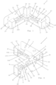
- FIG. 1 shows the element as it will be arranged on for instance a pallet to form a lower corner of a parallelepipedic cage-like structure, as it is in Fig. 5
- Fig. 3 shows the element as it will be arranged to form an upper corner of a said structure.
- the element 1 is made of one single flat material piece of metal bent to form the element as shown in the figures.
- the element comprises a bottom portion 2 with a flat surface 3 configured to bear on a thin side 4 of two first board-like members 5, such as wooden planks, of the structure meeting each other at the corner and each extending from the corner along a bottom or a top plane to an adjacent corner of the structure as shown in Fig. 4 .
- the element 1 has two outer wall portions 6, 7 to be located externally of the structure in the active state of the element, shown in Figs. 4 and 5 , and extending from the bottom portion 2 perpendicularly thereto so as to each form a lateral support to a wide side 8 of a respective said first board-like member 5 received in the element.
- the element 1 has two inner wall portions 9, 10 located opposite to the outer wall portions 6, 7 and in an active state of the element extending from the bottom portion 2 mainly in the same direction as the outer wall portions, i.e. each inner wall portion 9, 10 has a general extension which is parallel to the extension of the opposite outer wall portion 6, 7. There is a distance separating each couple of outer 6, 7 and inner 9, 10 wall portions so as to allow a said first board-like member 5 and a second board-like member 11 to be received therebetween, with wide sides 8, 12 of these board-like members bearing on each other.
- Each such second board-like member 11 is a part of the structure extending along an edge 13 between two adjacent walls 14, 15 of the structure between the bottom plane and the top plane thereof.
- the inner wall portions 9, 10 each comprises a spring member 90, 100 configured to, in a rest state (as seen in Figs.1 and 2 ), extend into a space 20 of the element at least partly towards the opposite outer wall portion 6, 7 and to be urged away from this outer wall portion by said first and second board-like members 5, 11 when received between a said couple of wall portions, as seen in Fig. 5 , while storing potential energy and bear onto and urge said second board-like member 11 to press said first board-like member 5 against said outer wall portion 6, 7.
- the first and second board-like members received between a couple of inner 9, 10 and outer 6, 7 wall portions in the active state of the element 1 are thus clamped between these wall portions by the resilient action of the respective spring member 90, 100.
- Each spring member 90, 100 has locking means comprising a retaining part 91, 101 in the form of a flap protruding from a main body 92, 102 of the spring member in a direction down towards the bottom portion 2 of the element 1.
- Each retaining part is configured to, in the active state of the element, bear onto and by the resilient action of the respective spring member urge a said second board-like member 11 in a direction at least partly down towards the bottom portion 2 so as to counteract movement of this board-like member 11 away from the bottom portion and out of said space 20.
- This design of each spring member 90, 100 and more specifically of the retaining parts 91, 101 thereof gives each spring member extra grip in a surface of a wide side 12 of a said second board-like member so that this board-like member is held in place even without screws.
- each retaining part 91, 101 is further configured to interact with locking means of a said second board-like member in the form of a recess 46, namely an elongated groove arranged at the surface of said wide side 12 of the second board-like member 11 and extending perpendicularly to the longitudinal extension thereof. More specifically, each retaining part 91, 101 is configured to be received in and engage with a said recess 46 in a locking position of the retaining part so as to fixedly secure the respective second board-like member 11 to the spring member 90, 100.
- each retaining part 91, 101 has a guide surface 93, 103 facing away from and pointing down towards the bottom portion 2 of the element 1.
- the guide surface is configured to receive a bottom side 47 of a said second board-like member 11 upon insertion thereof in said space 20 in a direction perpendicular to the bottom portion 2 (i.e. from above as seen in Fig. 5 ) and to guide this member 11 along the guide surface 93, 103 towards and past a lower edge 94 thereof.
- the second board-like member 11 brought past said lower edge of the guide surface is then allowed to be brought straight down towards the bottom portion 2 with the lower edge of the guide surface pressing against a wide side 12 of the second board-like member.
- the retaining part 91, 101 is thus configured to automatically snap out to the locking position, i.e. into the recess 46 as seen in Fig. 5 , once a first edge 48 of the recess has been brought past the lower edge 94 of the guide surface 93, 103.
- the spring member 90, 100 is pushed on an upper surface 95, 105 thereof facing away from the respective second board-like member 11 (see Fig. 5 ) making the retaining part come out of the recess 46 so that the second board-like member may be moved out of the space 20 of the element 1.
- the element 1 also has two wall members 16, 17 each extending from the bottom portion 2 perpendicularly, or at least substantially perpendicularly, to the outer 6, 7 and inner 9, 10 wall portions of a respective couple 6, 9 and 7, 10 of such wall portions to define an opening 18, 19 into the space 20 of the element defined by the wall portions and the wall member.
- Each such opening 18, 19 is directed along the extension of a said first board-like member 5 to be received in the space 20 with a width of this opening substantially corresponding to the thickness, i.e. the dimension of the thin side 4, of this member so as to form a support for and prevent the second board-like member 11 from leaving the space 20 in the direction of this opening along said plane. Accordingly, such second board-like members will each be held in place and bear on a wall member 16, 17 and an inner wall portion 9, 10.
- bottom portion 2 as well as the outer wall portions 6, 7 are provided with through-holes 21, 22 for securing these portions by screws to other components when desired, such as to a pallet or said board-like members.
- Each outer wall portion 6, 7 is also provided with an aperture 23 configured to receive a strap to be led to and through a corresponding aperture in a said element 1 arranged at the opposite of the top plane and the bottom plane of the structure and to be tightened for increasing the stability of the structure.
- These apertures 23 are located where the outer wall portions 6, 7 are joined to the bottom portion 2 and extend into the bottom portion as clearly visible in Figs. 1-3 facilitating introduction of a strap into these apertures while running from the aperture along opposite sides of the outer wall portion in the direction perpendicularly to the bottom portion.
- Each opening 18, 19 of the element 1 comprises a stop member 24, 25 extending from the bottom portion 2 in parallel with the respective said wall member 16, 17 to form a stop for an end 26 of a first board-like member 5 introduced through the opening.
- the two outer wall portions 6, 7 are connected to each other through the two stop members 24, 25 so that in an active state of the element, as shown in Fig. 4 , an outer recess 27 with a square cross-section as seen perpendicularly to the bottom portion is formed externally of the element 1 along said edge 13 of the structure.
- each outer wall portion 6, 7 is joined thereto provided with a slot 28 enabling folding of a part 29, 30 of the bottom portion out from the rest of the bottom portion to extend perpendicularly thereto in a direction opposite to the extension of the outer wall portions from the bottom portion for using this part as a guide for stacking a member onto the cage-like structure or securing a lid onto the structure by using a through-hole 31 therein for applying a screw.
- Fig. 4 shows how a cage-like structure may be formed by using elements 1 according to the invention in each corner 40 thereof where a bottom 41 or a top 42 plane of the structure meets two walls 14, 15 of the structure extending perpendicularly to this plane and to each other. It is seen how the elements at the lower corners of the structure may be secured onto a pallet 43 and first board-like members 5 be introduced into the elements to bear against the outer wall portions 6, 7 and second board-like members 11 be introduced therebehind to bear against the inner wall portions 9, 10 and the wall members 16, 17. This is also done at the upper corners of the structure by for instance applying the elements 1 from above onto the second board-like members and introducing the first board-like members from below into the elements and then securing them thereto by screws. Straps may then also be used for increasing the stability of the structure when desired. It is shown how the structure may be further reinforced by applying further board-like members 44, 45 thereto.
- the element may have any size, but it is preferred to provide several sizes, such as two sizes with 19 mm and 38 mm opening widths compatible with European and US lumber sizes.
- the flat surface of the bottom portion of the element will be directed upwardly when the element is used in a lower corner of the structure and be directed downwardly to have said board-like members thereunder when the element is used in an upper corner of the structure.
- each inner wall portion has a general extension which is parallel to the extension of the opposite outer wall portion
- each inner wall portion seen as one unit extends in parallel with the opposite outer wall portion, i.e. for instance upwardly as seen in Figs. 1 and 2 .
- Each inner and outer wall portion may be constituted by one continuous wall section only, or by two or more wall sections spaced apart.
Landscapes
- Engineering & Computer Science (AREA)
- Mechanical Engineering (AREA)
- Life Sciences & Earth Sciences (AREA)
- Wood Science & Technology (AREA)
- Rigid Containers With Two Or More Constituent Elements (AREA)
- Packaging Frangible Articles (AREA)
- Pallets (AREA)
- Connection Of Plates (AREA)
- Load-Bearing And Curtain Walls (AREA)
Applications Claiming Priority (2)
| Application Number | Priority Date | Filing Date | Title |
|---|---|---|---|
| SE1850225A SE542155C2 (en) | 2018-02-28 | 2018-02-28 | A corner element for a cage-like structure and a cage-like structure provided with such corner elements |
| PCT/SE2019/050171 WO2019168459A1 (en) | 2018-02-28 | 2019-02-26 | A corner element for a cage-like structure and a cage-like structure provided with such corner elements |
Publications (4)
| Publication Number | Publication Date |
|---|---|
| EP3759028A1 EP3759028A1 (en) | 2021-01-06 |
| EP3759028A4 EP3759028A4 (en) | 2021-10-27 |
| EP3759028B1 true EP3759028B1 (en) | 2024-03-27 |
| EP3759028C0 EP3759028C0 (en) | 2024-03-27 |
Family
ID=67805180
Family Applications (1)
| Application Number | Title | Priority Date | Filing Date |
|---|---|---|---|
| EP19760885.4A Active EP3759028B1 (en) | 2018-02-28 | 2019-02-26 | A corner element for a cage-like structure and a cage-like structure provided with such corner elements |
Country Status (6)
| Country | Link |
|---|---|
| US (1) | US12024334B2 (pl) |
| EP (1) | EP3759028B1 (pl) |
| ES (1) | ES2988056T3 (pl) |
| PL (1) | PL3759028T3 (pl) |
| SE (1) | SE542155C2 (pl) |
| WO (1) | WO2019168459A1 (pl) |
Families Citing this family (1)
| Publication number | Priority date | Publication date | Assignee | Title |
|---|---|---|---|---|
| EP3757030A1 (en) * | 2019-06-28 | 2020-12-30 | Nefab Packaging Netherlands | A corner clamp, a method of producing such a corner clamp, and a box structure |
Family Cites Families (10)
| Publication number | Priority date | Publication date | Assignee | Title |
|---|---|---|---|---|
| US3104024A (en) * | 1961-06-26 | 1963-09-17 | David D Eberly | Collapsible pallet box |
| US5722551A (en) * | 1996-07-19 | 1998-03-03 | Cocciemiglio, Jr.; Dominick | Crate assembly and panel connecting clip |
| GB9907605D0 (en) * | 1999-04-06 | 1999-05-26 | Sutcliffe Henry Ltd | Panel assembly |
| FR2848988B1 (fr) * | 2002-12-20 | 2005-01-28 | Renault Sa | Dispositif d'assemblage d'un moyen de conditionnement |
| FR2956384B1 (fr) | 2010-02-17 | 2013-08-16 | Groupe Dusogat | Element d'angle et caisse demontable renforcee |
| RU2603557C2 (ru) * | 2010-10-21 | 2016-11-27 | Груп Дюзога | Угловая накладка для приема стенок защитного каркаса и складной защитный каркас, который может быть собран и разобран |
| US8915390B2 (en) * | 2011-12-16 | 2014-12-23 | Groupe Dusogat | Shipping crate joint and method of forming a shipping crate |
| FR3010707B1 (fr) * | 2013-09-17 | 2016-04-15 | Pakers Mussy | Caisse assemblable et demontable |
| FR3013040B1 (fr) * | 2013-11-14 | 2016-12-30 | Vm Capital | Element d'angle pour la mise en volume d'une structure polygonale et structure polygonale dotee d'un ensemble de tels elements d'angle |
| CN206520843U (zh) * | 2016-10-25 | 2017-09-26 | 耐帆股份公司 | 布置在笼状结构的角部中的元件和笼状结构 |
-
2018
- 2018-02-28 SE SE1850225A patent/SE542155C2/en unknown
-
2019
- 2019-02-26 PL PL19760885.4T patent/PL3759028T3/pl unknown
- 2019-02-26 WO PCT/SE2019/050171 patent/WO2019168459A1/en not_active Ceased
- 2019-02-26 US US16/975,881 patent/US12024334B2/en active Active
- 2019-02-26 EP EP19760885.4A patent/EP3759028B1/en active Active
- 2019-02-26 ES ES19760885T patent/ES2988056T3/es active Active
Also Published As
| Publication number | Publication date |
|---|---|
| SE1850225A1 (en) | 2019-08-29 |
| US12024334B2 (en) | 2024-07-02 |
| ES2988056T3 (es) | 2024-11-19 |
| EP3759028A1 (en) | 2021-01-06 |
| SE542155C2 (en) | 2020-03-03 |
| PL3759028T3 (pl) | 2024-08-05 |
| US20210002025A1 (en) | 2021-01-07 |
| EP3759028A4 (en) | 2021-10-27 |
| WO2019168459A1 (en) | 2019-09-06 |
| EP3759028C0 (en) | 2024-03-27 |
Similar Documents
| Publication | Publication Date | Title |
|---|---|---|
| USRE48096E1 (en) | Reusable box blank | |
| US5037027A (en) | Tote box construction | |
| KR100263314B1 (ko) | 팔레트 | |
| US7000549B2 (en) | Corrugated pallet | |
| US6164477A (en) | Combined mortise and tenon joint feature | |
| DE102010011072B4 (de) | Kistenklammer, Transportkiste, Verfahren zum Zusammenbau einer Transportkiste, Verwendung einer Kistenklammer zur Führung eines Umreifungsbandes | |
| WO2002020358A1 (en) | Tote box with corner enhancers and multiple piece top rail | |
| EP3759028B1 (en) | A corner element for a cage-like structure and a cage-like structure provided with such corner elements | |
| KR102184292B1 (ko) | 포장상자의 바닥구조 및 이를 포함하는 포장상자 | |
| WO2000059789A1 (en) | Panel assembly | |
| WO2000078617A1 (en) | Tote box with corner enhancers and top rail | |
| JP6220606B2 (ja) | パレット固定具 | |
| JP6535155B2 (ja) | 運搬用容器 | |
| EP2816167B1 (en) | Wall element | |
| JP2015093706A (ja) | 運搬用容器 | |
| EP1810931B1 (en) | A clamp and a container | |
| CN206520843U (zh) | 布置在笼状结构的角部中的元件和笼状结构 | |
| JPS593935Y2 (ja) | 箱 | |
| CN220010398U (zh) | 一种组合型折叠纸箱 | |
| EP4072954B1 (de) | Faltkiste | |
| GB2343883A (en) | Component for attachment to sheet material | |
| CN211869946U (zh) | 包装容器及包装容器用片材 | |
| JPH07172440A (ja) | 仕切り付きコンテナ | |
| JPH0528194Y2 (pl) | ||
| KR101806018B1 (ko) | 목재부가 구비된 금속팔레트 |
Legal Events
| Date | Code | Title | Description |
|---|---|---|---|
| STAA | Information on the status of an ep patent application or granted ep patent |
Free format text: STATUS: THE INTERNATIONAL PUBLICATION HAS BEEN MADE |
|
| PUAI | Public reference made under article 153(3) epc to a published international application that has entered the european phase |
Free format text: ORIGINAL CODE: 0009012 |
|
| STAA | Information on the status of an ep patent application or granted ep patent |
Free format text: STATUS: REQUEST FOR EXAMINATION WAS MADE |
|
| 17P | Request for examination filed |
Effective date: 20200624 |
|
| AK | Designated contracting states |
Kind code of ref document: A1 Designated state(s): AL AT BE BG CH CY CZ DE DK EE ES FI FR GB GR HR HU IE IS IT LI LT LU LV MC MK MT NL NO PL PT RO RS SE SI SK SM TR |
|
| AX | Request for extension of the european patent |
Extension state: BA ME |
|
| DAV | Request for validation of the european patent (deleted) | ||
| DAX | Request for extension of the european patent (deleted) | ||
| A4 | Supplementary search report drawn up and despatched |
Effective date: 20210927 |
|
| RIC1 | Information provided on ipc code assigned before grant |
Ipc: B65D 19/16 20060101ALI20210921BHEP Ipc: B65D 19/38 20060101AFI20210921BHEP |
|
| REG | Reference to a national code |
Ref legal event code: R079 Free format text: PREVIOUS MAIN CLASS: B65D0019380000 Ipc: B65D0019140000 Ref country code: DE Ref document number: 602019049057 Country of ref document: DE |
|
| GRAP | Despatch of communication of intention to grant a patent |
Free format text: ORIGINAL CODE: EPIDOSNIGR1 |
|
| STAA | Information on the status of an ep patent application or granted ep patent |
Free format text: STATUS: GRANT OF PATENT IS INTENDED |
|
| RIC1 | Information provided on ipc code assigned before grant |
Ipc: B65D 6/34 20060101ALI20231006BHEP Ipc: B65D 19/14 20060101AFI20231006BHEP |
|
| INTG | Intention to grant announced |
Effective date: 20231115 |
|
| GRAS | Grant fee paid |
Free format text: ORIGINAL CODE: EPIDOSNIGR3 |
|
| GRAA | (expected) grant |
Free format text: ORIGINAL CODE: 0009210 |
|
| STAA | Information on the status of an ep patent application or granted ep patent |
Free format text: STATUS: THE PATENT HAS BEEN GRANTED |
|
| AK | Designated contracting states |
Kind code of ref document: B1 Designated state(s): AL AT BE BG CH CY CZ DE DK EE ES FI FR GB GR HR HU IE IS IT LI LT LU LV MC MK MT NL NO PL PT RO RS SE SI SK SM TR |
|
| REG | Reference to a national code |
Ref country code: GB Ref legal event code: FG4D |
|
| REG | Reference to a national code |
Ref country code: CH Ref legal event code: EP |
|
| REG | Reference to a national code |
Ref country code: DE Ref legal event code: R096 Ref document number: 602019049057 Country of ref document: DE |
|
| REG | Reference to a national code |
Ref country code: IE Ref legal event code: FG4D |
|
| U01 | Request for unitary effect filed |
Effective date: 20240424 |
|
| U07 | Unitary effect registered |
Designated state(s): AT BE BG DE DK EE FI FR IT LT LU LV MT NL PT SE SI Effective date: 20240502 |
|
| REG | Reference to a national code |
Ref country code: RO Ref legal event code: EPE |
|
| PG25 | Lapsed in a contracting state [announced via postgrant information from national office to epo] |
Ref country code: GR Free format text: LAPSE BECAUSE OF FAILURE TO SUBMIT A TRANSLATION OF THE DESCRIPTION OR TO PAY THE FEE WITHIN THE PRESCRIBED TIME-LIMIT Effective date: 20240628 |
|
| PG25 | Lapsed in a contracting state [announced via postgrant information from national office to epo] |
Ref country code: HR Free format text: LAPSE BECAUSE OF FAILURE TO SUBMIT A TRANSLATION OF THE DESCRIPTION OR TO PAY THE FEE WITHIN THE PRESCRIBED TIME-LIMIT Effective date: 20240327 Ref country code: RS Free format text: LAPSE BECAUSE OF FAILURE TO SUBMIT A TRANSLATION OF THE DESCRIPTION OR TO PAY THE FEE WITHIN THE PRESCRIBED TIME-LIMIT Effective date: 20240627 |
|
| PG25 | Lapsed in a contracting state [announced via postgrant information from national office to epo] |
Ref country code: RS Free format text: LAPSE BECAUSE OF FAILURE TO SUBMIT A TRANSLATION OF THE DESCRIPTION OR TO PAY THE FEE WITHIN THE PRESCRIBED TIME-LIMIT Effective date: 20240627 Ref country code: NO Free format text: LAPSE BECAUSE OF FAILURE TO SUBMIT A TRANSLATION OF THE DESCRIPTION OR TO PAY THE FEE WITHIN THE PRESCRIBED TIME-LIMIT Effective date: 20240627 Ref country code: HR Free format text: LAPSE BECAUSE OF FAILURE TO SUBMIT A TRANSLATION OF THE DESCRIPTION OR TO PAY THE FEE WITHIN THE PRESCRIBED TIME-LIMIT Effective date: 20240327 Ref country code: GR Free format text: LAPSE BECAUSE OF FAILURE TO SUBMIT A TRANSLATION OF THE DESCRIPTION OR TO PAY THE FEE WITHIN THE PRESCRIBED TIME-LIMIT Effective date: 20240628 |
|
| REG | Reference to a national code |
Ref country code: SK Ref legal event code: T3 Ref document number: E 44292 Country of ref document: SK |
|
| PG25 | Lapsed in a contracting state [announced via postgrant information from national office to epo] |
Ref country code: IS Free format text: LAPSE BECAUSE OF FAILURE TO SUBMIT A TRANSLATION OF THE DESCRIPTION OR TO PAY THE FEE WITHIN THE PRESCRIBED TIME-LIMIT Effective date: 20240727 |
|
| PG25 | Lapsed in a contracting state [announced via postgrant information from national office to epo] |
Ref country code: SM Free format text: LAPSE BECAUSE OF FAILURE TO SUBMIT A TRANSLATION OF THE DESCRIPTION OR TO PAY THE FEE WITHIN THE PRESCRIBED TIME-LIMIT Effective date: 20240327 |
|
| PG25 | Lapsed in a contracting state [announced via postgrant information from national office to epo] |
Ref country code: CZ Free format text: LAPSE BECAUSE OF FAILURE TO SUBMIT A TRANSLATION OF THE DESCRIPTION OR TO PAY THE FEE WITHIN THE PRESCRIBED TIME-LIMIT Effective date: 20240327 |
|
| PG25 | Lapsed in a contracting state [announced via postgrant information from national office to epo] |
Ref country code: SM Free format text: LAPSE BECAUSE OF FAILURE TO SUBMIT A TRANSLATION OF THE DESCRIPTION OR TO PAY THE FEE WITHIN THE PRESCRIBED TIME-LIMIT Effective date: 20240327 Ref country code: IS Free format text: LAPSE BECAUSE OF FAILURE TO SUBMIT A TRANSLATION OF THE DESCRIPTION OR TO PAY THE FEE WITHIN THE PRESCRIBED TIME-LIMIT Effective date: 20240727 Ref country code: CZ Free format text: LAPSE BECAUSE OF FAILURE TO SUBMIT A TRANSLATION OF THE DESCRIPTION OR TO PAY THE FEE WITHIN THE PRESCRIBED TIME-LIMIT Effective date: 20240327 |
|
| REG | Reference to a national code |
Ref country code: ES Ref legal event code: FG2A Ref document number: 2988056 Country of ref document: ES Kind code of ref document: T3 Effective date: 20241119 |
|
| REG | Reference to a national code |
Ref country code: DE Ref legal event code: R097 Ref document number: 602019049057 Country of ref document: DE |
|
| PLBE | No opposition filed within time limit |
Free format text: ORIGINAL CODE: 0009261 |
|
| STAA | Information on the status of an ep patent application or granted ep patent |
Free format text: STATUS: NO OPPOSITION FILED WITHIN TIME LIMIT |
|
| 26N | No opposition filed |
Effective date: 20250103 |
|
| U20 | Renewal fee for the european patent with unitary effect paid |
Year of fee payment: 7 Effective date: 20250218 |
|
| PGFP | Annual fee paid to national office [announced via postgrant information from national office to epo] |
Ref country code: RO Payment date: 20250130 Year of fee payment: 7 |
|
| PGFP | Annual fee paid to national office [announced via postgrant information from national office to epo] |
Ref country code: ES Payment date: 20250303 Year of fee payment: 7 |
|
| PGFP | Annual fee paid to national office [announced via postgrant information from national office to epo] |
Ref country code: CH Payment date: 20250301 Year of fee payment: 7 |
|
| PGFP | Annual fee paid to national office [announced via postgrant information from national office to epo] |
Ref country code: PL Payment date: 20250129 Year of fee payment: 7 |
|
| PGFP | Annual fee paid to national office [announced via postgrant information from national office to epo] |
Ref country code: SK Payment date: 20250128 Year of fee payment: 7 Ref country code: GB Payment date: 20250219 Year of fee payment: 7 |
|
| PGFP | Annual fee paid to national office [announced via postgrant information from national office to epo] |
Ref country code: TR Payment date: 20250203 Year of fee payment: 7 |
|
| PG25 | Lapsed in a contracting state [announced via postgrant information from national office to epo] |
Ref country code: MC Free format text: LAPSE BECAUSE OF FAILURE TO SUBMIT A TRANSLATION OF THE DESCRIPTION OR TO PAY THE FEE WITHIN THE PRESCRIBED TIME-LIMIT Effective date: 20240327 |
|
| PG25 | Lapsed in a contracting state [announced via postgrant information from national office to epo] |
Ref country code: IE Free format text: LAPSE BECAUSE OF NON-PAYMENT OF DUE FEES Effective date: 20250226 |