EP3759008B1 - Anhängerwinkelbestimmungssystem für ein fahrzeug - Google Patents
Anhängerwinkelbestimmungssystem für ein fahrzeug Download PDFInfo
- Publication number
- EP3759008B1 EP3759008B1 EP19709622.5A EP19709622A EP3759008B1 EP 3759008 B1 EP3759008 B1 EP 3759008B1 EP 19709622 A EP19709622 A EP 19709622A EP 3759008 B1 EP3759008 B1 EP 3759008B1
- Authority
- EP
- European Patent Office
- Prior art keywords
- trailer
- vehicle
- distance
- angle
- determination system
- Prior art date
- Legal status (The legal status is an assumption and is not a legal conclusion. Google has not performed a legal analysis and makes no representation as to the accuracy of the status listed.)
- Active
Links
Images

Classifications
-
- G—PHYSICS
- G06—COMPUTING OR CALCULATING; COUNTING
- G06T—IMAGE DATA PROCESSING OR GENERATION, IN GENERAL
- G06T7/00—Image analysis
- G06T7/60—Analysis of geometric attributes
-
- B—PERFORMING OPERATIONS; TRANSPORTING
- B62—LAND VEHICLES FOR TRAVELLING OTHERWISE THAN ON RAILS
- B62D—MOTOR VEHICLES; TRAILERS
- B62D15/00—Steering not otherwise provided for
- B62D15/02—Steering position indicators ; Steering position determination; Steering aids
- B62D15/021—Determination of steering angle
- B62D15/023—Determination of steering angle by measuring on the king pin
-
- B—PERFORMING OPERATIONS; TRANSPORTING
- B60—VEHICLES IN GENERAL
- B60D—VEHICLE CONNECTIONS
- B60D1/00—Traction couplings; Hitches; Draw-gear; Towing devices
- B60D1/01—Traction couplings or hitches characterised by their type
- B60D1/06—Ball-and-socket hitches
-
- B—PERFORMING OPERATIONS; TRANSPORTING
- B60—VEHICLES IN GENERAL
- B60D—VEHICLE CONNECTIONS
- B60D1/00—Traction couplings; Hitches; Draw-gear; Towing devices
- B60D1/58—Auxiliary devices
- B60D1/62—Auxiliary devices involving supply lines, electric circuits or the like
-
- B—PERFORMING OPERATIONS; TRANSPORTING
- B62—LAND VEHICLES FOR TRAVELLING OTHERWISE THAN ON RAILS
- B62D—MOTOR VEHICLES; TRAILERS
- B62D13/00—Steering specially adapted for trailers
- B62D13/06—Steering specially adapted for trailers for backing a normally drawn trailer
-
- B—PERFORMING OPERATIONS; TRANSPORTING
- B62—LAND VEHICLES FOR TRAVELLING OTHERWISE THAN ON RAILS
- B62D—MOTOR VEHICLES; TRAILERS
- B62D15/00—Steering not otherwise provided for
- B62D15/02—Steering position indicators ; Steering position determination; Steering aids
- B62D15/027—Parking aids, e.g. instruction means
-
- G—PHYSICS
- G01—MEASURING; TESTING
- G01B—MEASURING LENGTH, THICKNESS OR SIMILAR LINEAR DIMENSIONS; MEASURING ANGLES; MEASURING AREAS; MEASURING IRREGULARITIES OF SURFACES OR CONTOURS
- G01B11/00—Measuring arrangements characterised by the use of optical techniques
- G01B11/14—Measuring arrangements characterised by the use of optical techniques for measuring distance or clearance between spaced objects or spaced apertures
-
- G—PHYSICS
- G01—MEASURING; TESTING
- G01B—MEASURING LENGTH, THICKNESS OR SIMILAR LINEAR DIMENSIONS; MEASURING ANGLES; MEASURING AREAS; MEASURING IRREGULARITIES OF SURFACES OR CONTOURS
- G01B11/00—Measuring arrangements characterised by the use of optical techniques
- G01B11/26—Measuring arrangements characterised by the use of optical techniques for measuring angles or tapers; for testing the alignment of axes
-
- G—PHYSICS
- G06—COMPUTING OR CALCULATING; COUNTING
- G06T—IMAGE DATA PROCESSING OR GENERATION, IN GENERAL
- G06T7/00—Image analysis
- G06T7/50—Depth or shape recovery
-
- G—PHYSICS
- G06—COMPUTING OR CALCULATING; COUNTING
- G06T—IMAGE DATA PROCESSING OR GENERATION, IN GENERAL
- G06T7/00—Image analysis
- G06T7/70—Determining position or orientation of objects or cameras
- G06T7/73—Determining position or orientation of objects or cameras using feature-based methods
-
- G—PHYSICS
- G06—COMPUTING OR CALCULATING; COUNTING
- G06T—IMAGE DATA PROCESSING OR GENERATION, IN GENERAL
- G06T2207/00—Indexing scheme for image analysis or image enhancement
- G06T2207/30—Subject of image; Context of image processing
- G06T2207/30248—Vehicle exterior or interior
-
- G—PHYSICS
- G06—COMPUTING OR CALCULATING; COUNTING
- G06T—IMAGE DATA PROCESSING OR GENERATION, IN GENERAL
- G06T2207/00—Indexing scheme for image analysis or image enhancement
- G06T2207/30—Subject of image; Context of image processing
- G06T2207/30248—Vehicle exterior or interior
- G06T2207/30252—Vehicle exterior; Vicinity of vehicle
Definitions
- the invention relates to a trailer angle determination system for a vehicle, a vehicle with such a trailer angle determination system, a method for determining the angle between a vehicle and a trailer, a program element and a computer-readable medium.
- Driver assistance systems are increasingly being installed in modern vehicles to support the driver while driving. For many drivers, driving and maneuvering with a trailer is a challenge.
- the driver can be supported by a driver assistance system.
- the driver assistance system can provide the driver with useful information about how to correctly control the vehicle with the trailer.
- the angle between the vehicle and the trailer can be crucial here. Particularly if trailers are changed frequently, for example in the logistics industry, the angle between the trailer and the vehicle must be determined quickly, easily and reliably using such a driver assistance system.
- WO 2017/123880 A1 describes a method for controlling a support system for a vehicle and trailer assembly.
- An image of a trailer hitch for the vehicle and trailer arrangement is recorded with a camera coupled to the vehicle.
- An electronic control unit is used to learn multiple distances in relation to the geometry of the vehicle and trailer and to identify a variety of reference points on the trailer. Furthermore, the electronic control unit learns several reference distances that relate to the large number of reference points. A current coupling angle is then determined using the multiple reference distances and geometry distances.
- a first aspect of the invention relates to a trailer angle determination system.
- the trailer angle determination system has a detection unit for detecting a trailer connected to the vehicle and an evaluation unit.
- the detection unit is arranged outside the center of the vehicle and towards the trailer and the distance between the detection unit and the center of the vehicle is known.
- the trailer has symmetrical pairs of features relative to a longitudinal axis of symmetry of the trailer.
- the detection unit is set up to detect the symmetrical feature pairs of the trailer and identify them as such.
- the evaluation unit is set up to determine the angle between the trailer and the vehicle, for example based exclusively on the detected symmetrical feature pairs of the trailer and the known distance between the detection unit and the center of the vehicle.
- the trailer angle determination system can determine the angle between a vehicle and a trailer connected to the vehicle.
- a detection unit can be arranged outside the center of the vehicle, which detects the trailer.
- the trailer can have pairs of features that are symmetrical to a longitudinal axis of symmetry of the trailer.
- the features of the feature pairs can include corners, edges, lighting, reflectors, Hinges, beads, grooves or receptacles of the trailer, but the features can also be specially applied patterns or objects. These symmetrical feature pairs can be evaluated by the evaluation unit in such a way that it can determine the angle between the vehicle and the trailer.
- the distance between the vehicle and the respective pair of features of the trailer can be determined.
- the detection unit can determine the angle of the lines of sight, the angle between the detection unit and the respective feature, to the main direction (parallel to the center of the vehicle). In other words, the detection unit can determine the direction of the feature.
- This distance information can be included in determining the angle between the vehicle and the trailer. In particular, how the angle of the lines of sight of the respective features changes from the perspective of the detection unit due to the rotation or the angle between the vehicle and the trailer.
- the initialization of the trailer angle determination system can be carried out based on an image or a frame, eliminating the need for lengthy training or the use of special markings. This allows the trailer angle determination system described above and below to quickly adapt to a new trailer. The flexibility of the system can thus be increased.
- the trailer angle determination system described above and below allows trailers to be changed quickly without the need for lengthy training.
- the specific angle between the vehicle and the trailer can be used for controlling a vehicle with a trailer especially when maneuvering.
- the driver of the vehicle can be given instructions on how to correctly steer the vehicle with the trailer.
- Correct steering of a vehicle with a trailer can play a role, especially when maneuvering the vehicle with a trailer.
- the angle between another vehicle, a caravan, a horse transport or a boat trailer and your own vehicle can also be determined.
- the trailer can also be another vehicle, for example when it is being towed.
- center of the vehicle is meant the longitudinal axis of the vehicle, which can also be a longitudinal axis of symmetry.
- the center of the vehicle can serve as a reference if the towbar is located in the middle of the vehicle.
- the detection unit is specifically arranged outside the longitudinal axis of the trailer coupling. This means that it does not necessarily have to be in the middle of the vehicle, but the detection unit can be arranged outside the longitudinal axis of symmetry of the trailer if the angle between the trailer and the vehicle is 0° or 180°.
- the capture unit is a mono camera that captures image data of the trailer.
- the detection unit can consist of a camera that carries out an initialization based on an image.
- a stereo camera or other sensors are not necessary for this invention.
- the image data of the trailer can be symmetrical Features of the trailer so that the angle between the vehicle and the trailer can be reliably determined.
- the evaluation unit is set up to determine at least two pairs of features, which are symmetrical to the longitudinal axis of symmetry of the trailer, in the image data of the detection unit and to determine the angle between the trailer and the vehicle based on the detected pairs of features.
- the evaluation unit can detect or determine at least two pairs of features that are symmetrical to the longitudinal axis of symmetry of the trailer. By changing the angle of the lines of sight of the detection unit, i.e. at what angle the respective feature of the pair of features was detected by the detection unit, the evaluation unit can determine the angle between the vehicle and the trailer. In other words, the evaluation unit can determine how much the trailer has rotated relative to the vehicle.
- the pivot point e.g. the trailer hitch
- its distance from the vehicle can be known to the evaluation unit. This makes it easier to determine the angle between the vehicle and the trailer because the pivot point is known.
- the distance between the pivot point (e.g. a trailer hitch) and the vehicle can be determined once by the trailer angle determination system, since this distance does not change for a particular vehicle.
- the change in the angle of the respective line of sight of the individual features of the at least two pairs of features can be used.
- the distance between the feature and the detection unit can be determined at an angle of 0° or 180°.
- the evaluation unit is set up to determine the distance between the trailer and the vehicle based on the distance between the detection unit and the center of the vehicle and the positions of the at least two symmetrical feature pairs of the trailer in the image data.
- the distance between the vehicle and the trailer can be determined using the detected feature pairs and the known distance between the detection unit and the center of the vehicle when the center of the vehicle and the longitudinal axis of symmetry of the trailer are in a line. In other words, when the angle between the vehicle and the trailer is 0° or 180°.
- x is the distance between the vehicle and trailer
- y c is the distance between the detection unit and the center of the vehicle
- ⁇ r and ⁇ l are the angles of the features of the feature pair with respect to the main visual axis of the detection unit.
- the above formula can be derived by transformation and various assumptions.
- the distance between the two symmetrical features of a feature pair to the longitudinal axis of symmetry of the trailer can be the same, for example y r and y l , where the distance y 1 between the features of the feature pair can be, from which it follows that 0.5*y 1 is equal to y r and y l .
- two right-angled triangles can be defined, with the first right-angled triangle being the first Feature of the feature pair includes and the second right triangle includes the second feature of the feature pair.
- the length of the opposite side of the first right-angled triangle can be described as y l +y c or as 0.5*y 1 +y c and the length of the opposite side of the second right triangle can be described as y r -y c or as 0.5*y 1 -y c .
- the length of the adjacent side of the first right-angled triangle and the length of the adjacent side of the second right-angled triangle are identical and correspond to the distance x between the vehicle and the feature of the trailer.
- the angle of the line of sight between the detection unit and the respective feature can be referred to as ⁇ r or ⁇ l and these can be determined directly by the detection unit.
- the distance x between the vehicle and the trailer can be determined depending on the known distance y c between the detection unit and the center of the vehicle and the known angles ⁇ r and ⁇ l at which the first pair of features was detected by the detection unit.
- the evaluation unit is set up to determine the distance between the vehicle and trailer by initialization based on an image in which the center of the vehicle and the longitudinal axis of symmetry of the trailer are in one line.
- the distance between the vehicle and the trailer or the features of the feature pairs of the trailer can be determined; this can serve as a starting point for the later determination of the angle between the vehicle and the trailer.
- This distance can be determined if the longitudinal axis of symmetry of the trailer is equal to the center of the vehicle, since then the distance between the two features of the feature pair and the vehicle is the same.
- the initialization can be carried out when the angle between the vehicle and the trailer is 0° or 180°.
- Another aspect of the invention relates to a vehicle with a trailer angle determination system described above and below.
- the vehicle is, for example, a motor vehicle, such as a car, a bus or a truck.
- steps of the method can also be carried out in a different order or simultaneously. Furthermore, there can be a longer period of time between individual steps.
- Another aspect of the invention relates to a program element that, when applied to an evaluation unit
- a further aspect of the invention relates to a computer-readable medium on which a program element is stored, which, when applied to an evaluation unit of a trailer angle determination system, instructs the evaluation unit to carry out the method described above and below.
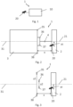
- Fig. 1 shows a block diagram of a trailer angle determination system 1.
- the trailer angle determination system 1 has a detection unit 20 and an evaluation unit 10.
- the detection unit 20 is designed to capture image data of a trailer which is connected to the vehicle of the trailer angle determination system 1. Furthermore, the trailer has symmetrical pairs of features relative to a longitudinal axis of symmetry of the trailer. Furthermore, the detection unit 20 is arranged outside the center of the vehicle and has an orientation parallel to the center of the vehicle.
- the evaluation unit 10 can determine the angle between the vehicle and the trailer based on the image data captured by the capture unit 20 and the known distance between the capture unit 20 and the center of the vehicle. Furthermore, the detection unit 20 can determine the angle at which an object or a feature is located to the detection unit along the line of sight of the detection unit 20.
- this trailer angle determination system 1 only requires an image or a frame from the detection unit 20, in which the center of the vehicle and the longitudinal axis of symmetry of the trailer are in one line. This allows the distance between the vehicle and the trailer or the features of the pair of features of the trailer to be determined.
- Fig. 2 shows a schematic representation of the trailer angle determination system on a vehicle 2.
- a detection unit 20 for example a camera
- the vehicle 2 has a center 21 (longitudinal axis of the vehicle) (shown as a dashed line).
- the detection unit is specifically arranged outside this center 21 of the vehicle 2 at a distance y c .
- a trailer 3 is connected to the vehicle via a rotatable coupling 4.
- the trailer also has a longitudinal axis of symmetry 31 (shown as a dashed line). The distance between the vehicle and the trailer is called x.
- the trailer 3 has features 35, 36, 37, 38 that are symmetrical to its longitudinal axis of symmetry 31.
- These features 35, 36, 37, 38 are respectively in pairs 35, 38; 36, 37 used to determine the angle between the vehicle 2 and the trailer 3. Furthermore, the detection unit 20 can detect the symmetrical features 35, 36, 37, 38 of the trailer 3 and the evaluation unit can evaluate these in such a way that the angle between the vehicle 2 and the trailer 3 can be determined.
- the angle here is the angle between the longitudinal axis or the center 21 of the vehicle 2 and the longitudinal axis of symmetry 31 of the trailer 3.
- Fig. 3 also shows a schematic representation of the trailer angle determination system. In contrast to Fig. 2 For reasons of clarity, the trailer and the coupling between the trailer and the vehicle 2 were removed. Furthermore, the distance y 1 between the first pair of features 35, 38 and the distance y 2 between the second pair of features 36, 37 are shown. It should be noted here that the distance between the longitudinal axis of symmetry 31 of the trailer and the features of the first pair of features 35, 38 is the same and amounts to 0.5*y 1 . Furthermore, the distance between the longitudinal axis of symmetry 31 of the trailer and the features of the second pair of features 36, 37 is the same and amounts to 0.5*y 2 .
- Fig. 4 shows a schematic view of determining the distance between the vehicle and the trailer when the center 21 of the vehicle and the longitudinal axis of symmetry 31 of the trailer are the same.
- the detection unit 20 is specifically arranged outside the center 21 of the vehicle and the distance y c between the center 21 of the vehicle and the detection unit 20 is known.
- the angle ⁇ l, ⁇ r is known by the detection unit 20 at which the image data of the respective symmetrical features of the feature pair are received.
- the detection unit 20 detects at least one symmetrical Pair of features 35, 38 of the trailer.
- the distance y l , y r between the respective feature 35, 38 and the longitudinal axis of symmetry 31 of the trailer is identical and corresponds to 0.5*y 1 in each case.
- two right-angled triangles can be formed from the perspective of the detection unit 20.
- the first right triangle includes the first feature 35 of the first pair of features 35, 38 and the distance x between the vehicle and the trailer and the second right triangle includes the second feature 38 of the first pair of features 35, 38 and the distance x.
- the length of the opposite side of the first right-angled triangle can be described as y l +y c or as 0.5 * y 1 +y c and the length of the The opposite side of the second right triangle can be described as y r -y c or as 0.5*y 1 -y c .
- the length of the adjacent side of the first right-angled triangle and the length of the adjacent side of the second right-angled triangle are identical and correspond to the distance x between the vehicle and the trailer.
- 0.5*y 1 +y c is equal to x*tan ( ⁇ l ) and 0.5*y 1 -y c is equal to x*tan ( ⁇ r ).
- the symmetry of features 35, 38 also means that 0.5*y 1 is equal to x*tan( ⁇ l )-y c and at the same time equal to x*tan( ⁇ r )+y c .
- the distance x between the vehicle and the trailer can be determined depending on the known distance y c between the detection unit and the longitudinal axis of symmetry of the trailer and the known angles at which the first pair of features 35, 38 were detected by the detection unit 20.
- Fig. 5 shows a schematic representation of the correct distance determination of the individual pairs of features 35, 38; 36, 37.
- the dotted circles symbolize the possible Positions of the features from the perspective of the detection unit 20 along the lines of sight of the detection unit 20. These can be located at any position along the line of sight (dashed arrow starting from the detection unit 20).
- the solid circles symbolize the actual positions of the features 35, 36, 37, 38 of the trailer 3.
- the actual position of the respective pairs of features 35, 38; 36, 37 can be used using the method Fig. 4 has been described. With the specific positions of the symmetrical feature pairs 35, 38; 36, 37 during initialization, the angle between the vehicle 2 and the trailer 3 can then be determined during operation of the trailer angle determination system.
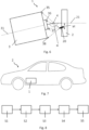
- Fig. 6 shows the trailer angle determination system during operation.
- the angle ⁇ between the vehicle 2 and the trailer 3 is not equal to 0° or 180°, whereby the trailer 3 has rotated around the coupling 4.
- the symmetrical feature pairs 35, 38; 36, 37 change the angle of the line of sight between the respective feature 35, 36, 37, 38 and the detection unit 20 due to the rotation.
- the angle ⁇ between the vehicle 2 and the trailer 3 can be concluded by the evaluation unit.
- the position of the coupling 4 and thus of the pivot point can also be known, which simplifies the calculation of the angle ⁇ between the vehicle 2 and the trailer 3.
- Fig. 7 shows a vehicle 2 with a trailer angle determination system 1 described above and below.
- Fig. 8 shows a flowchart for a method for determining the angle between a vehicle and a trailer connected to the vehicle.
- step S1 the trailer is detected by the detection unit; the detection unit is arranged outside the center in the direction of the trailer.
- the distance between the detection unit and the center of the vehicle is determined.
- step S3 features of the trailer that are symmetrical to the longitudinal axis of symmetry of the trailer are recorded by the evaluation unit.
- the distance between the vehicle and the trailer is determined when the center of the vehicle and the longitudinal axis of symmetry of the trailer are in line.
- step 5 the angle between the vehicle and the trailer is determined based on the symmetrical characteristics of the trailer and the known distance between the detection unit and the center of the vehicle, as well as the determined distance between the vehicle and the trailer.
Landscapes
- Engineering & Computer Science (AREA)
- Physics & Mathematics (AREA)
- General Physics & Mathematics (AREA)
- Transportation (AREA)
- Mechanical Engineering (AREA)
- Computer Vision & Pattern Recognition (AREA)
- Theoretical Computer Science (AREA)
- Chemical & Material Sciences (AREA)
- Combustion & Propulsion (AREA)
- Geometry (AREA)
- Length Measuring Devices By Optical Means (AREA)
- Image Analysis (AREA)
Description
- Die Erfindung betrifft ein Anhängerwinkelbestimmungssystem für ein Fahrzeug, ein Fahrzeug mit einem solchen Anhängerwinkelbestimmungssystem, ein Verfahren zur Bestimmung des Winkels zwischen einem Fahrzeug und einem Anhänger, ein Programmelement und einem computerlesbaren Medium.
- In modernen Fahrzeugen werden zunehmend Fahrerassistenzsysteme verbaut, um den Fahrer während des Fahrens zu unterstützen. Für viele Fahrer stellt das Fahren sowie das Rangieren mit einem Anhänger eine Herausforderung dar. Der Fahrer kann hierbei durch ein Fahrerassistenzsystem unterstützt werden. Insbesondere beim Rangieren kann der Fahrer durch das Fahrerassistenzsystem nützliche Informationen über das richtige Steuern des Fahrzeugs mit dem Anhänger erhalten. Hierbei kann der Winkel zwischen dem Fahrzeug und dem Anhänger entscheidend sein. Insbesondere wenn die Anhänger oft getauscht werden, beispielsweise in der Logistikbranche, muss der Winkel zwischen dem Anhänger und dem Fahrzeug durch ein solches Fahrerassistenzsystem schnell, einfach und verlässlich bestimmt werden.
-
WO 2017/123880 A1 beschreibt ein Verfahren zum Steuern eines Trägersystems für eine Fahrzeug- und Anhängeranordnung. Dabei wird ein Bild einer Anhängerkupplung für die Fahrzeug- und Anhängeranordnung mit einer an das Fahrzeug gekoppelten Kamera aufgezeichnet. Mit einem elektronischen Steuergerät werden mehrere Abstände in Bezug auf die Geometrie des Fahrzeugs und des Anhängers gelernt und eine Vielzahl von Referenzpunkten auf dem Anhänger identifiziert. Des Weiteren werden mit dem elektronischen Steuergerät mehrere Referenzabstände gelernt, die sich auf die Vielzahl von Referenzpunkten beziehen. Ein aktueller Kupplungswinkel wird sodann unter Verwendung der mehreren Referenzabstände und Geometrieabstände bestimmt. - Es ist eine Aufgabe der Erfindung, den Winkel zwischen einem Fahrzeug und einem Anhänger zu bestimmen.
- Diese Aufgabe wird durch den Gegenstand der unabhängigen Ansprüche gelöst. Ausführungsformen und Weiterbildungen sind den abhängigen Ansprüchen, der Beschreibung und den Figuren zu entnehmen.
- Ein erster Aspekt der Erfindung betrifft ein Anhängerwinkelbestimmungssystem. Das Anhängerwinkelbestimmungssystem weist eine Erfassungseinheit zur Erfassung eines mit dem Fahrzeug verbundenen Anhängers und eine Auswerteeinheit auf. Die Erfassungseinheit ist außerhalb der Mitte des Fahrzeugs und in Richtung des Anhängers angeordnet und der Abstand zwischen der Erfassungseinheit und der Mitte des Fahrzeugs ist bekannt. Der Anhänger weist symmetrische Merkmalspaare zu einer Längssymmetrieachse des Anhängers auf. Die Erfassungseinheit ist dazu eingerichtet, die symmetrischen Merkmalspaare des Anhängers zu erfassen und als solche zu identifizieren. Die Auswerteeinheit ist dazu eingerichtet, beispielsweise ausschließlich basierend auf den erfassten symmetrischen Merkmalspaaren des Anhängers und dem bekannten Abstand zwischen der Erfassungseinheit und der Mitte des Fahrzeugs den Winkel zwischen dem Anhänger und dem Fahrzeug zu bestimmen.
- Das Anhängerwinkelbestimmungssystem kann den Winkel zwischen einem Fahrzeug und einem mit dem Fahrzeug verbundenen Anhänger bestimmen. Hierzu kann eine Erfassungseinheit außerhalb der Mitte des Fahrzeugs angeordnet sein, welche den Anhänger erfasst. Ferner kann der Anhänger zu einer Längssymmetrieachse des Anhängers symmetrische Merkmalspaare aufweisen. Die Merkmale der Merkmalspaare können Ecken, Kanten, Beleuchtungen, Reflektoren, Scharniere, Sicken, Nuten oder Aufnahmen des Anhängers sein, aber die Merkmale können auch speziell angebrachte Muster oder Objekte sein. Diese symmetrischen Merkmalspaare können durch die Auswerteeinheit derart ausgewertet werden, dass diese den Winkel zwischen dem Fahrzeug und dem Anhänger bestimmen kann. Ferner kann in einer Initialisierung, bei welcher der Winkel zwischen dem Fahrzeug und dem Anhänger 0° bzw. 180° ist, der Abstand zwischen dem Fahrzeug und dem jeweiligen Merkmalspaar des Anhängers bestimmt werden. Ferner kann die Erfassungseinheit den Winkel der Sichtlinien, der Winkel zwischen der Erfassungseinheit und dem jeweiligen Merkmal, zu der Hauptrichtung (parallel zur Mitte des Fahrzeugs) bestimmen. Mit anderen Worten, kann die Erfassungseinheit die Richtung des Merkmals bestimmen. Diese Abstandsinformation kann in die Bestimmung des Winkels zwischen dem Fahrzeug und dem Anhänger miteinfließen. Insbesondere wie sich der Winkel der Sichtlinien der jeweiligen Merkmale aus Sicht der Erfassungseinheit durch die Drehung bzw. den Winkel zwischen dem Fahrzeug und dem Anhänger ändert. Die Initialisierung des Anhängerwinkelbestimmungssystems kann basierend auf einem Bild bzw. einem Frame durchgeführt werden, sodass ein langwieriges Training oder eine Verwendung von speziellen Markierungen entfallen kann. Hierdurch kann sich das vorhergehend und nachfolgend beschriebene Anhängerwinkelbestimmungssystem schnell an einen neuen Anhänger anpassen. Somit kann die Flexibilität des Systems erhöht werden.
- Durch das oben und nachfolgend beschriebene Anhängerwinkelbestimmungssystem können schnell die Anhänger gewechselt werden, ohne dass ein langwieriges Einlernen erforderlich ist.
- Der bestimmte Winkel zwischen dem Fahrzeug und dem Anhänger kann für die Steuerung eines Fahrzeugs mit einem Anhänger verwendet werden, insbesondere beim Rangieren. Alternativ oder zusätzlich kann, abhängig vom Winkel, dem Fahrer des Fahrzeugs ein Hinweis über das richtige Steuern des Fahrzeugs mit dem Anhänger gegeben werden. Das richtige Steuern eines Fahrzeugs mit Anhänger kann insbesondere beim Rangieren des Fahrzeugs mit Anhänger eine Rolle spielen.
- Alternativ oder zusätzlich kann neben dem Anhänger auch der Winkel zwischen einem weiteren Fahrzeug, einem Wohnwagen, einem Pferdetransport oder einem Bootsanhänger und dem eigenen Fahrzeug bestimmt werden. Mit anderen Worten kann der Anhänger auch ein weiteres Fahrzeug sein, beispielsweise, wenn dieses abgeschleppt wird.
- Es sei angemerkt, dass mit Mitte des Fahrzeugs die Längsachse des Fahrzeugs gemeint ist, welche ebenfalls eine Längssymmetrieachse sein kann. Die Mitte des Fahrzeugs kann als Referenz dienen, wenn sich die Anhängerkupplung mittig am Fahrzeug befindet. Ferner sei angemerkt, dass im Allgemeinen die Erfassungseinheit gezielt außerhalt der Längsachse der Anhängerkupplung angeordnet ist. Somit muss es sich nicht zwingend im die Mitte des Fahrzeugs handeln, sondern die Erfassungseinheit kann außerhalb der Längssymmetrieachse des Anhängers angeordnet sein, wenn der Winkel zwischen Anhänger und Fahrzeug 0° bzw. 180° beträgt.
- Gemäß einer Ausführungsform der Erfindung ist die Erfassungseinheit eine Mono-Kamera, welche Bilddaten des Anhängers erfasst.
- Die Erfassungseinheit kann aus einer Kamera bestehen, welche auf Basis eines Bildes eine Initialisierung durchführt. Eine Stereo-Kamera oder weitere Sensoren sind für diese Erfindung nicht nötig. Die Bilddaten des Anhängers können symmetrische Merkmale des Anhängers aufweisen, sodass eine sichere Ermittlung des Winkels zwischen dem Fahrzeug und dem Anhänger möglich ist.
- Gemäß einer Ausführungsform der Erfindung ist die Auswerteeinheit dazu eingerichtet, wenigstens zwei Merkmalspaare, welche symmetrisch zur Längssymmetrieachse des Anhängers sind, in den Bilddaten der Erfassungseinheit zu bestimmen und basierend auf den erfassten Merkmalspaaren den Winkel zwischen Anhänger und Fahrzeug zu bestimmen.
- Für eine verlässliche Bestimmung des Winkels zwischen dem Fahrzeug und dem Anhänger kann die Auswerteeinheit wenigstens zwei zur Längssymmetrieachse des Anhängers symmetrische Merkmalspaare erfassen bzw. bestimmen. Durch die jeweilige Veränderung des Winkels der Sichtlinien der Erfassungseinheit, also unter welchem Winkel das jeweilige Merkmal des Merkmalspaars durch die Erfassungseinheit erfasst wurde, kann die Auswerteeinheit den Winkel zwischen dem Fahrzeug und dem Anhänger bestimmen. Mit anderen Worten kann die Auswerteeinheit bestimmen um wieviel sich der Anhänger gegenüber dem Fahrzeug gedreht hat. Alternativ oder zusätzlich kann der Auswerteeinheit der Drehpunkt, z.B. die Anhängerkupplung, und deren Abstand zu dem Fahrzeug bekannt sein. Dadurch kann die Bestimmung des Winkels zwischen dem Fahrzeug und dem Anhänger vereinfacht werden, da der Drehpunkt bekannt ist. Ferner kann der Abstand zwischen dem Drehpunkt (z.B. eine Anhängerkupplung) und dem Fahrzeug einmal durch das Anhängerwinkelbestimmungssystem bestimmt werden, da sich dieser Abstand für ein bestimmtes Fahrzeug nicht ändert.
- Hierzu kann die Veränderung des Winkels der jeweiligen Sichtlinie der einzelnen Merkmale der wenigstens zwei Merkmalspaare herangezogen werden. In einer durchgeführten Initialisierung kann der Abstand zwischen dem Merkmal und der Erfassungseinheit bei einem Winkel von 0° bzw. 180° bestimmt werden.
- Gemäß einer weiteren Ausführungsform der Erfindung ist die Auswerteeinheit dazu eingerichtet, den Abstand zwischen Anhänger und Fahrzeug basierend auf dem Abstand zwischen der Erfassungseinheit und der Mitte des Fahrzeugs und den Positionen der wenigstens zwei symmetrischen Merkmalspaare des Anhängers in den Bilddaten zu bestimmen.
- Der Abstand zwischen dem Fahrzeug und dem Anhänger kann mittels der erkannten Merkmalspaare und dem bekannten Abstand zwischen der Erfassungseinheit und der Mitte des Fahrzeugs bestimmt werden, wenn die Mitte des Fahrzeugs und die Längssymmetrieachse des Anhängers sich in einer Linie befinden. Mit anderen Worten wenn die Winkel zwischen dem Fahrzeug und dem Anhänger 0° bzw. 180° ist.
- Gemäß einer Ausführungsform der Erfindung wird der Abstand zwischen Fahrzeug und Anhänger gemäß dieser Formel berechnet:

- Die obere Formel kann durch Umformung und durch verschiedene Annahmen hergeleitet werden. Der Abstand zwischen den beiden symmetrischen Merkmalen eines Merkmalpaares zu der Längssymmetrieachse des Anhängers kann gleich sein, beispielsweise yr und yl, wobei der Abstand y1 zwischen den Merkmalen des Merkmalspaar sein kann, woraus folgt, dass 0,5*y1 gleich ist zu yr und yl. Ferner können zwei rechtwinklige Dreiecke definiert werden, wobei das erste rechtwinklige Dreieck das erste Merkmal des Merkmalspaars beinhaltet und das zweite rechtwinklige Dreieck das zweite Merkmal des Merkmalspaars beinhaltet. Durch die Anordnung der Erfassungseinheit in einem bekannten Abstand yc zu der Mitte des Fahrzeugs kann die Länge der Gegenkathete des ersten rechtwinkligen Dreiecks als yl+yc bzw. als 0,5*y1+yc beschrieben werden und die Länge der Gegenkathete des zweiten rechtwinkligen Dreiecks kann als yr-yc bzw. als 0,5*y1-yc beschrieben werden. Die Länge der Ankathete des ersten rechtwinkligen Dreiecks und die Länge der Ankathete des zweiten rechtwinkligen Dreiecks sind identisch und entsprechen dem Abstand x zwischen dem Fahrzeug und dem Merkmal des Anhängers. Der Winkel der Sichtlinie zwischen der Erfassungseinheit und dem jeweiligen Merkmal kann als αr bzw. αl bezeichnet werden und diese können direkt durch die Erfassungseinheit bestimmt werden. Ferner gilt, dass 0,5*y1+yc gleich x*tan(αl) ist und 0,5*y1-yc gleich x*tan(αr) ist. Des Weiteren gilt durch die Symmetrie der Merkmale, dass 0,5*y1 gleich x*tan(αl)-yc und gleichzeitig gleich x*tan(αr)+yc ist. Somit können diese beiden Formeln für 0,5*y1 gleichgesetzt werden und derart nach x umgestellt werden, dass

- Erfindungsgemäß ist die Auswerteeinheit dazu eingerichtet, den Abstand zwischen Fahrzeug und Anhänger durch eine Initialisierung basierend auf einem Bild zu bestimmen, in welcher die Mitte des Fahrzeugs und die Längssymmetrieachse des Anhängers in einer Linie.
- Bei der Initialisierung des Anhängerwinkelbestimmungssystems kann der Abstand zwischen dem Fahrzeug und dem Anhänger bzw. den Merkmalen der Merkmalspaare des Anhängers bestimmt werden, dieser kann als Ausgangsbasis für die spätere Bestimmung des Winkels zwischen dem Fahrzeug und dem Anhänger dienen. Dieser Abstand kann bestimmt werden, wenn die Längssymmetrieachse des Anhängers gleich der Mitte des Fahrzeugs ist, da dann hier der Abstand zwischen den beiden Merkmalen des Merkmalspaars und dem Fahrzeug gleich ist. Mit anderen Worten kann die Initialisierung durchgeführt werden, wenn der Winkel zwischen dem Fahrzeug und dem Anhänger 0° bzw. 180° beträgt.
- Ein weiterer Aspekt der Erfindung betrifft ein Fahrzeug mit einem vorhergehend und nachfolgend beschriebenen Anhängerwinkelbestimmungssystem.
- Bei dem Fahrzeug handelt es sich beispielsweise um ein Kraftfahrzeug, wie ein Auto, ein Bus oder einen Lastkraftwagen.
- Ein weiterer Aspekt der Erfindung betrifft ein Verfahren zur Bestimmung des Winkels zwischen einem Fahrzeug und einem mit dem Fahrzeug verbundenen Anhänger. Das Verfahren weist die folgenden Schritte auf:
- Erfassen des Anhängers durch eine Erfassungseinheit, welche außerhalb der Mitte des Fahrzeugs in Richtung des Anhängers angeordnet ist;
- Bestimmen des Abstands zwischen der Erfassungseinheit und einer Mitte des Fahrzeugs;
- Erfassen von zur Längssymmetrieachse des Anhängers symmetrischen Merkmalen;
- Bestimmen des Abstandes zwischen dem Fahrzeug und dem Anhänger, wenn die Längssymmetrieachse des Anhängers und die Mitte des Fahrzeugs in einer Linie sind; und
- Bestimmen des Winkels zwischen dem Fahrzeug und dem Anhänger basierend auf den symmetrischen Merkmalen des Anhängers und dem bekannten Abstand zwischen Erfassungseinheit und der Mitte des Fahrzeugs.
- Es sei angemerkt, dass die Schritte des Verfahrens auch in einer anderen Reihenfolge oder gleichzeitig ausgeführt werden können. Ferner kann zwischen einzelnen Schritten auch eine längere Zeitspanne liegen.
- Ein weiterer Aspekt der Erfindung betrifft ein Programmelement, das, wenn es auf eine Auswerteeinheit eines
- Anhängerwinkelbestimmungssystems ausgeführt werden, die Auswerteeinheit anleitet, das vorhergehend und nachfolgend beschriebene Verfahren durchzuführen.
- Ein weiterer Aspekt der Erfindung betrifft ein computerlesbares Medium, auf dem ein Programmelement gespeichert ist, das, wenn es auf eine Auswerteeinheit eines Anhängerwinkelbestimmungssystems, die Auswerteeinheit anleitet, das vorhergehend und nachfolgend beschriebene Verfahren durchzuführen.
- Weitere Merkmale, Vorteile und Anwendungsmöglichkeiten der Erfindung ergeben sich aus der nachfolgenden Beschreibung der Ausführungsbeispiele und der Figuren.
- Die Figuren sind schematisch und nicht maßstabsgetreu. Sind in der nachfolgenden Beschreibung der Figuren gleiche Bezugszeichen angegeben, so bezeichnen diese gleiche oder ähnliche Elemente.
-
Fig. 1 zeigt ein Blockschaltbild eines Anhängerwinkelbestimmungssystems gemäß einer Ausführungsform der Erfindung. -
Fig. 2 zeigt eine schematische Darstellung eines Fahrzeugs mit einem Anhängerwinkelbestimmungssystem und einem Anhänger gemäß einer Ausführungsform der Erfindung. -
Fig. 3 zeigt eine schematische Darstellung der durch das Anhängerwinkelbestimmungssystem erkannten Merkmale des Anhängers gemäß einer Ausführungsform der Erfindung. -
Fig. 4 zeigt eine schematische Darstellung der Berechnung des Abstandes zwischen dem Fahrzeug und dem Anhänger gemäß einer Ausführungsform der Erfindung. -
Fig. 5 zeigt eine schematische Darstellung der möglichen Positionen der Merkmale des Anhängers aus Sicht des Anhängerwinkelbestimmungssystems gemäß einer Ausführungsform der Erfindung. -
Fig. 6 zeigt das Anhängerwinkelbestimmungssystem welches den Winkel zwischen dem Fahrzeug und dem Anhänger bestimmt hat, gemäß einer Ausführungsform der Erfindung. -
Fig. 7 zeigt ein Fahrzeug mit einem Anhängerwinkelbestimmungssystem gemäß einer Ausführungsform der Erfindung. -
Fig. 8 zeigt ein Flussdiagramm für ein Verfahren zur Bestimmung eines Winkels zwischen einem Fahrzeug und einem Anhänger gemäß einer Ausführungsform der Erfindung. -
Fig. 1 zeigt eine Blockschaltbild eines Anhängerwinkelbestimmungssystems 1. Das Anhängerwinkelbestimmungssystem 1 weist eine Erfassungseinheit 20 und eine Auswerteeinheit 10 auf. Die Erfassungseinheit 20 ist dazu ausgeführt Bilddaten eines Anhängers, welcher mit dem Fahrzeug des Anhängerwinkelbestimmungssystems 1 verbunden ist, zu erfassen. Des Weiteren weist der Anhänger zu einer Längssymmetrieachse des Anhängers symmetrische Merkmalspaare auf. Ferner ist die Erfassungseinheit 20 außerhalb der Mitte des Fahrzeugs angeordnet und weist eine zur Mitte des Fahrzeugs parallele Ausrichtung auf. Die Auswerteeinheit 10 kann basierend auf den erfassten Bilddaten der Erfassungseinheit 20 und dem bekannten Abstand zwischen Erfassungseinheit 20 und der Mitte des Fahrzeugs den Winkel zwischen dem Fahrzeug und dem Anhänger bestimmen. Ferner kann die Erfassungseinheit 20, entlang der Sichtlinie der Erfassungseinheit 20, den Winkel bestimmen in welchem sich ein Objekt bzw. ein Merkmal zu der Erfassungseinheit befindet. Für die Kalibrierung benötigt dieses Anhängerwinkelbestimmungssystem 1 lediglich ein Bild bzw. einen Frame der Erfassungseinheit 20, bei welchem die Mitte des Fahrzeugs und die Längssymmetrieachse des Anhängers in einer Linie sind. Hierdurch kann der Abstand zwischen dem Fahrzeug und dem Anhänger bzw. den Merkmalen des Merkmalspaars des Anhängers bestimmt werden. -
Fig. 2 zeigt eine schematische Darstellung des Anhängerwinkelbestimmungssystems an einem Fahrzeug 2. Hierzu ist eine Erfassungseinheit 20, z.B. eine Kamera, an dem Fahrzeug 2 angeordnet. Das Fahrzeug 2 weist eine Mitte 21 (Längsachse des Fahrzeugs) auf (als gestrichelte Linie dargestellt). Die Erfassungseinheit ist gezielt außerhalb dieser Mitte 21 des Fahrzeugs 2 in dem Abstand yc angeordnet. Ferner ist ein Anhänger 3 mit dem Fahrzeug über eine drehbare Kupplung 4 verbunden. Der Anhänger weist ebenfalls eine Längssymmetrieachse 31 auf (als gestrichelte Linie dargestellt). Der Abstand zwischen dem Fahrzeug und dem Anhänger wird als x bezeichnet. Der Anhänger 3 weist zu seiner Längssymmetrieachse 31 symmetrische Merkmale 35, 36, 37, 38 auf. Diese Merkmale 35, 36, 37, 38 werden jeweils paarweise 35, 38; 36, 37 zur Bestimmung des Winkels zwischen dem Fahrzeug 2 und dem Anhänger 3 verwendet. Des Weiteren kann die Erfassungseinheit 20 die symmetrischen Merkmale 35, 36, 37, 38 des Anhängers 3 erfassen und die Auswerteeinheit kann diese derart auswerten, dass der Winkel zwischen dem Fahrzeug 2 und dem Anhänger 3 bestimmt werden kann. Der Winkel ist hierbei der Winkel zwischen der Längsachse bzw. der Mitte 21 des Fahrzeugs 2 und der Längssymmetrieachse 31 des Anhängers 3. -
Fig. 3 zeigt ebenfalls eine schematische Darstellung des Anhängerwinkelbestimmungssystems. Im Unterschied zuFig. 2 wurde aus Gründen der Übersichtlichkeit der Anhänger und die Kupplung zwischen dem Anhänger und dem Fahrzeug 2 entfernt. Des Weiteren ist der Abstand y1 zwischen dem ersten Merkmalspaar 35, 38 und der Abstand y2 zwischen dem zweiten Merkmalspaar 36, 37 dargestellt. Hierbei ist festzuhalten, dass der Abstand zwischen der Längssymmetrieachse 31 des Anhängers und den Merkmalen des ersten Merkmalspaars 35, 38 gleich ist und 0,5*y1 beträgt. Ferner ist der Abstand zwischen der Längssymmetrieachse 31 des Anhängers und den Merkmalen des zweiten Merkmalspaars 36, 37 gleich und beträgt 0,5*y2. -
Fig. 4 zeigt eine schematische Ansicht der Bestimmung des Abstands zwischen dem Fahrzeug und dem Anhänger, wenn die Mitte 21 des Fahrzeugs und die Längssymmetrieachse 31 des Anhängers gleich sind. Hierzu wird in diesem Fall ein Bild bzw. ein Frame mit symmetrischen Merkmalspaaren des Anhängers benötigt. Die Erfassungseinheit 20 ist hierbei gezielt außerhalb der Mitte 21 des Fahrzeugs angeordnet und der Abstand yc zwischen der Mitte 21 des Fahrzeugs und der Erfassungseinheit 20 ist bekannt. Des Weiteren ist der Winkel αl, αr durch die Erfassungseinheit 20 bekannt, unter welchem die Bilddaten der jeweiligen symmetrischen Merkmale des Merkmalspaars empfangen werden. Die Erfassungseinheit 20 erfasst wenigstens ein symmetrisches Merkmalspaar 35, 38 des Anhängers. Hierbei ist der Abstand yl, yr zwischen dem jeweiligen Merkmal 35, 38 und der Längssymmetrieachse 31 des Anhängers identisch und entspricht jeweils 0,5*y1. Nun können zwei rechtwinklige Dreiecke aus Sicht der Erfassungseinheit 20 gebildet werden. Das erste rechtwinklige Dreieck umfasst das erste Merkmal 35 des ersten Merkmalspaars 35, 38 und den Abstand x zwischen dem Fahrzeug und dem Anhänger und das zweite rechtwinklige Dreieck umfasst das zweite Merkmal 38 des ersten Merkmalspaars 35, 38 und den Abstand x. Durch die Anordnung der Erfassungseinheit 20 in einem Abstand yc zu der Mitte 21 des Fahrzeugs kann die Länge der Gegenkathete des ersten rechtwinkligen Dreiecks als yl+yc bzw. als 0,5*y1+yc beschrieben werden und die Länge der Gegenkathete des zweiten rechtwinkligen Dreiecks kann als yr-yc bzw. als 0,5*y1-yc beschrieben werden. Die Länge der Ankathete des ersten rechtwinkligen Dreiecks und die Länge die Ankathete des zweiten rechtwinkligen Dreiecks sind identisch und entsprechen dem Abstand x zwischen dem Fahrzeug und dem Anhänger. Ferner gilt, dass 0,5*y1+yc gleich x*tan (αl) ist und 0,5*y1-yc gleich x*tan (αr) ist. Auch gilt durch die Symmetrie der Merkmale 35, 38, dass 0,5*y1 gleich x*tan(αl)-yc und gleichzeitig gleich x*tan(αr)+yc ist. Somit können diese beiden Formeln für 0,5*y1 gleichgesetzt werden und derart nach x umgestellt werden, dass
-
Fig. 5 zeigt eine schematische Darstellung der korrekten Abstandsbestimmung der einzelnen Merkmalspaare 35, 38; 36, 37. Hierbei symbolisieren die gepunkteten Kreise die Möglichen Positionen der Merkmale aus Sicht der Erfassungseinheit 20 entlang der Sichtlinien der Erfassungseinheit 20. Diese können sich an einer beliebigen Position entlang der Sichtlinie (gestrichelter Pfeil ausgehend von der Erfassungseinheit 20) befinden. Die durchgezogenen Kreise symbolisieren die tatsächlichen Positionen der Merkmale 35, 36, 37, 38 des Anhängers 3. Die tatsächliche Position der jeweiligen Merkmalspaare 35, 38; 36, 37 kann über die Methode, welche anhandFig. 4 beschrieben wurde, bestimmt werden. Mit den bestimmten Positionen der symmetrischen Merkmalspaare 35, 38; 36, 37 während der Initialisierung kann anschließend während des Betriebs des Anhängerwinkelbestimmungssystems der Winkel zwischen dem Fahrzeug 2 und dem Anhänger 3 bestimmt werden. -
Fig. 6 zeigt das Anhängerwinkelbestimmungssystem während des Betriebs. Der Winkel α zwischen dem Fahrzeug 2 und dem Anhänger 3 ist hier ungleich 0° bzw. 180°, wobei sich der Anhänger 3 um die Kupplung 4 gedreht hat. Die symmetrischen Merkmalspaare 35, 38; 36, 37 ändern durch die Drehung den Winkel der Sichtlinie zwischen dem jeweiligen Merkmal 35, 36, 37, 38 und der Erfassungseinheit 20. Durch die Winkeländerung der Sichtlinie der wenigstens zwei symmetrischen Merkmalspaare 35, 38; 36, 37 und dem vorher bekannten Abstand x zwischen dem Fahrzeug 2 und dem Anhänger 3 kann durch die Auswerteeinheit auf den Winkel α zwischen dem Fahrzeug 2 und dem Anhänger 3 geschlossen werden. In einer weiteren Ausführungsform kann ferner die Position der Kupplung 4 und somit des Drehpunktes bekannt sein, wodurch sich die Berechnung des Winkels α zwischen dem Fahrzeug 2 und dem Anhänger 3 vereinfacht. -
Fig. 7 zeigt ein Fahrzeug 2 mit einem vorhergehend und nachfolgend beschriebenen Anhängerwinkelbestimmungssystem 1. -
Fig. 8 zeigt ein Flussdiagramm für ein Verfahren zur Bestimmung des Winkels zwischen einem Fahrzeug und einem mit dem Fahrzeug verbundenen Anhänger. In Schritt S1 wird der Anhänger durch die Erfassungseinheit erfasst, die Erfassungseinheit ist hierbei außerhalb der Mitte in Richtung des Anhängers angeordnet. In Schritt 2 wird der Abstand zwischen der Erfassungseinheit und der Mitte des Fahrzeugs bestimmt. In Schritt S3 werden durch die Auswerteeinheit zur Längssymmetrieachse des Anhängers symmetrische Merkmale des Anhängers erfasst. In Schritt S4 wird der Abstand zwischen dem Fahrzeug und dem Anhänger bestimmt, wenn die Mitte des Fahrzeugs und die Längssymmetrieachse des Anhängers in einer Linie sind. In Schritt 5 wird der Winkel zwischen dem Fahrzeug und dem Anhänger basierend auf den symmetrischen Merkmalen des Anhängers und dem Bekannten Abstand zwischen Erfassungseinheit und der Mitte des Fahrzeugs, sowie dem bestimmten Abstand zwischen dem Fahrzeug und dem Anhänger, bestimmt.
Claims (9)
- Anhängerwinkelbestimmungssystem (1) für ein Fahrzeug (2), aufweisend:- eine Erfassungseinheit (20) zur Erfassung eines mit dem Fahrzeug (2) verbundenen Anhängers (3); und- eine Auswerteeinheit (10),wobei die Erfassungseinheit (20) außerhalb der Mitte (21) des Fahrzeugs (2) und in Richtung des Anhängers (3) angeordnet ist und wobei der Abstand (yc) zwischen der Erfassungseinheit (20) und der Mitte (21) des Fahrzeugs (2) bekannt ist,wobei der Anhänger (3) symmetrische Merkmalspaare (35, 38; 36, 37) zu einer Längssymmetrieachse (31) des Anhängers (3) aufweist,wobei die Erfassungseinheit (20) dazu eingerichtet ist, zumindest die symmetrischen Merkmalspaare (35, 38; 36, 37) des Anhängers (3) zu erfassen,wobei die Auswerteeinheit (10) dazu eingerichtet ist, basierend auf den erfassten symmetrischen Merkmalspaaren (35, 38; 36, 37) des Anhängers (3) und dem bekannten Abstand (yc) zwischen der Erfassungseinheit (20) und der Mitte (21) des Fahrzeugs (2) den Winkel (α) zwischen dem Anhänger (3) und dem Fahrzeug (2) zu bestimmen,dadurch gekennzeichnet,
dass die Auswerteeinheit (10) dazu eingerichtet ist, den Abstand (x) zwischen dem Fahrzeug (2) und dem Anhänger (3) durch eine Initialisierung basierend auf einem Bild zu bestimmen, in welcher die Mitte (21) des Fahrzeugs (2) und die Längssymmetrieachse (31) des Anhängers (3) in einer Linie sind. - Anhängerwinkelbestimmungssystem (1) gemäß Anspruch 1,
wobei die Erfassungseinheit (20) eine Mono-Kamera ist und Bilddaten des Anhängers (3) erfasst. - Anhängerwinkelbestimmungssystem (1) gemäß Anspruch 2,
wobei die Auswerteeinheit (10) dazu eingerichtet ist, wenigstens zwei Merkmalspaare (35, 38; 36, 37), welche symmetrisch zur Längssymmetrieachse (31) des Anhängers (3) sind, in den Bilddaten der Erfassungseinheit (20) zu bestimmen und basierend auf den erfassten Merkmalspaaren (35, 38; 36, 37) den Winkel zwischen dem Anhänger (3) und dem Fahrzeug (2) zu bestimmen. - Anhängerwinkelbestimmungssystem (1) gemäß einem der vorhergehenden Ansprüche,
wobei die Auswerteeinheit (10) dazu eingerichtet ist, den Abstand (x) zwischen dem Anhänger (3) und dem Fahrzeug (2) basierend auf dem Abstand (yc) zwischen der Erfassungseinheit (20) und der Mitte (21) des Fahrzeugs und den Positionen der wenigstens zwei symmetrischen Merkmalspaare (35, 38; 36, 37) des Anhängers (3) in den Bilddaten zu bestimmen. - Anhängerwinkelbestimmungssystem (1) gemäß Anspruch 4, wobei der Abstand (x) zwischen dem Fahrzeug (2) und dem Anhänger (3) gemäß dieser Formel berechnet wird:

- Fahrzeug (2) mit einem Anhängerwinkelbestimmungssystem (1) gemäß einem der Ansprüche 1 bis 5.
- Verfahren zur Bestimmung des Winkels zwischen einem Fahrzeug und einem mit dem Fahrzeug verbundenen Anhänger, folgende Schritte aufweisend:- Erfassen (S1) des Anhängers durch eine Erfassungseinheit, welche außerhalb der Mitte des Fahrzeugs in Richtung des Anhängers angeordnet ist;- Bestimmen (S2) des Abstands zwischen der Erfassungseinheit und einer Mitte des Fahrzeugs;- Erfassen (S3) von zur Längssymmetrieachse des Anhängers symmetrischen Merkmalspaaren;- Bestimmen (S4) des Abstandes zwischen dem Fahrzeug und dem Anhänger, wenn die Längssymmetrieachse des Anhängers und die Mitte des Fahrzeugs in einer Linie sind; und- Bestimmen (S5) des Winkels zwischen dem Fahrzeug und dem Anhänger basierend auf den symmetrischen Merkmalspaaren des Anhängers und dem bekannten Abstand zwischen Erfassungseinheit und der Mitte des Fahrzeugs.
- Programmelement, welches, wenn durch eine Auswerteeinheit eines Anhängerwinkelbestimmungssystems ausgeführt, die Auswerteeinheit dazu anleitet, das Verfahren gemäß Anspruch 7 durchzuführen.
- Computerlesbares Medium, auf welchem ein Programmelement gemäß Anspruch 8 gespeichert ist.
Applications Claiming Priority (2)
| Application Number | Priority Date | Filing Date | Title |
|---|---|---|---|
| DE102018203152.5A DE102018203152A1 (de) | 2018-03-02 | 2018-03-02 | Anhängerwinkelbestimmungssystem für ein Fahrzeug |
| PCT/DE2019/200019 WO2019166065A1 (de) | 2018-03-02 | 2019-02-26 | Anhängerwinkelbestimmungssystem für ein fahrzeug |
Publications (3)
| Publication Number | Publication Date |
|---|---|
| EP3759008A1 EP3759008A1 (de) | 2021-01-06 |
| EP3759008B1 true EP3759008B1 (de) | 2024-01-17 |
| EP3759008B8 EP3759008B8 (de) | 2024-06-26 |
Family
ID=65717689
Family Applications (1)
| Application Number | Title | Priority Date | Filing Date |
|---|---|---|---|
| EP19709622.5A Active EP3759008B8 (de) | 2018-03-02 | 2019-02-26 | Anhängerwinkelbestimmungssystem für ein fahrzeug |
Country Status (4)
| Country | Link |
|---|---|
| US (1) | US11941834B2 (de) |
| EP (1) | EP3759008B8 (de) |
| DE (1) | DE102018203152A1 (de) |
| WO (1) | WO2019166065A1 (de) |
Families Citing this family (12)
| Publication number | Priority date | Publication date | Assignee | Title |
|---|---|---|---|---|
| KR102650306B1 (ko) * | 2018-10-16 | 2024-03-22 | 주식회사 에이치엘클레무브 | 차량 제어 시스템, 차량 제어 방법 |
| JP7271416B2 (ja) * | 2019-12-27 | 2023-05-11 | 株式会社クボタ | 作業車両及び作業車両の走行管理システム |
| DE102020108416A1 (de) * | 2020-03-26 | 2021-09-30 | Zf Cv Systems Global Gmbh | Verfahren zum Ermitteln einer Pose eines Objektes, Verfahren zum Steuern eines Fahrzeuges, Steuereinheit und Fahrzeug |
| EP3889904B1 (de) * | 2020-03-31 | 2023-01-11 | Continental Autonomous Mobility Germany GmbH | Verfahren und system zur berechnung des fahrzeuganhängerwinkels |
| EP3889906B1 (de) | 2020-03-31 | 2024-11-13 | Continental Autonomous Mobility Germany GmbH | Verfahren und system zur berechnung des fahrzeuganhängerwinkels |
| EP3889903B1 (de) | 2020-03-31 | 2024-10-23 | Continental Autonomous Mobility Germany GmbH | Verfahren und system zur berechnung des fahrzeuganhängerwinkels |
| CN112161580B (zh) * | 2020-09-03 | 2021-10-22 | 中联重科股份有限公司 | 支腿跨距测量方法及设备 |
| JP7594495B2 (ja) * | 2021-05-21 | 2024-12-04 | 株式会社クボタ | 屈曲角の判定方法および判定装置 |
| JP2023163795A (ja) * | 2022-04-28 | 2023-11-10 | 株式会社ジェイテクト | 連結車両の相対角度検出装置 |
| CN115131285B (zh) * | 2022-04-29 | 2024-09-06 | 盛视科技股份有限公司 | 拖挂车转向夹角的检测方法及转向夹角的检测系统 |
| CN114993209B (zh) * | 2022-04-29 | 2026-03-10 | 盛视科技股份有限公司 | 基于视觉的拖挂车车厢倾斜角检测方法及检测系统 |
| CN114872790B (zh) * | 2022-04-29 | 2023-04-07 | 盛视科技股份有限公司 | 基于视觉的拖挂车的转向夹角的检测方法及检测系统 |
Family Cites Families (8)
| Publication number | Priority date | Publication date | Assignee | Title |
|---|---|---|---|---|
| DE102006056408B4 (de) * | 2006-11-29 | 2013-04-18 | Universität Koblenz-Landau | Verfahren zum Bestimmen einer Position, Vorrichtung und Computerprogrammprodukt |
| WO2009036176A1 (en) * | 2007-09-11 | 2009-03-19 | Magna Electronics | Imaging system for vehicle |
| US9446713B2 (en) * | 2012-09-26 | 2016-09-20 | Magna Electronics Inc. | Trailer angle detection system |
| CN108778784B (zh) * | 2016-01-14 | 2021-10-15 | 大陆汽车系统公司 | 用于车辆和拖车组件的倒车系统和用于控制其的方法 |
| US10391939B2 (en) * | 2016-09-01 | 2019-08-27 | GM Global Technology Operations LLC | Method and apparatus to determine trailer pose |
| KR101859045B1 (ko) * | 2016-11-02 | 2018-05-17 | 엘지전자 주식회사 | 차량용 운전 보조 장치 및 차량 |
| US10885652B2 (en) * | 2017-03-22 | 2021-01-05 | Magna Electronics Inc. | Trailer angle detection system for vehicle |
| US10638025B2 (en) * | 2017-03-22 | 2020-04-28 | Magna Electronics Inc. | Vehicular trailering assist sytem |
-
2018
- 2018-03-02 DE DE102018203152.5A patent/DE102018203152A1/de not_active Withdrawn
-
2019
- 2019-02-26 EP EP19709622.5A patent/EP3759008B8/de active Active
- 2019-02-26 WO PCT/DE2019/200019 patent/WO2019166065A1/de not_active Ceased
-
2020
- 2020-09-01 US US17/008,907 patent/US11941834B2/en active Active
Also Published As
| Publication number | Publication date |
|---|---|
| DE102018203152A1 (de) | 2019-09-05 |
| EP3759008B8 (de) | 2024-06-26 |
| US20210019904A1 (en) | 2021-01-21 |
| EP3759008A1 (de) | 2021-01-06 |
| WO2019166065A1 (de) | 2019-09-06 |
| US11941834B2 (en) | 2024-03-26 |
Similar Documents
| Publication | Publication Date | Title |
|---|---|---|
| EP3759008B1 (de) | Anhängerwinkelbestimmungssystem für ein fahrzeug | |
| EP2953838B1 (de) | Verfahren und vorrichtung zum vorwärtseinparken eines kraftfahrzeugs in eine querparklücke | |
| DE102014114812B4 (de) | Vorrichtung zur Ermittlung eines Knickwinkels und Verfahren dazu | |
| EP3413086A1 (de) | Verfahren zum charakterisieren eines an ein zugfahrzeug angehängten anhängers, fahrerassistenzsystem sowie gespann | |
| DE102019131702A1 (de) | Anhängerwinkelerfassung unter verwendung von ende-zu-ende-lernen | |
| EP3356203B1 (de) | Verfahren zum bestimmen einer parkfläche zum parken eines kraftfahrzeugs, fahrerassistenzsystem sowie kraftfahrzeug | |
| EP3012154B1 (de) | Verfahren und vorrichtung zur unterstützung eines fahrers eines fahrzeug-gespanns, insbesondere eines nutzfahrzeug-gespanns | |
| DE102017120227A1 (de) | Verfahren und vorrichtung zum bestimmen einer anhängerstellung | |
| DE102018206494A1 (de) | Verfahren zum Betreiben eines Anhängerrangierassistenzsystems eines Kraftfahrzeugs und Anhängerrangierassistenzsystem für ein Kraftfahrzeug | |
| DE102018100306B4 (de) | Fahrzeugrückfahrunterstützungssystem | |
| DE102013206345A1 (de) | Anzeigevorrichtung und Verfahren zum Anzeigen von Daten und Fahrerassistenzsystem für ein Fahrzeug | |
| DE102015105720A1 (de) | Verfahren zum Bestimmen einer jeweiligen Einbauposition von zumindest zwei Sensoren eines Kraftfahrzeugs, Steuereinrichtung, Fahrerassistenzsystem sowie Kraftfahrzeug | |
| WO2017059991A1 (de) | Funktionsfähigkeitsprüfung eines fahrerassistenzsystems | |
| EP3476696A1 (de) | Verfahren zum ermitteln von objektgrenzen eines objekts in einem aussenbereich eines kraftfahrzeugs sowie steuervorrichtung und kraftfahrzeug | |
| DE102018113559A1 (de) | Verfahren zum Erkennen einer Fahrbahnmarkierung durch Validieren anhand der Linienbreite; Steuereinrichtung; Stellplatzerkennungssystem; sowie Fahrerassistenzsystem | |
| DE102011100672B4 (de) | Lenkunterstützung bei spurrinnen | |
| DE102008057670B4 (de) | Verfahren zur Unterstützung eines Fahrzeugführers eines Fahrzeuges, insbesondere bei einer Rückwärtsfahrt | |
| DE102019201677A1 (de) | Steuervorrichtung und -verfahren sowie Computer-Programm-Produkt zum Betreiben eines Fahrzeugs für eine Wechselbrücke | |
| DE102020005136A1 (de) | Verfahren zum automatischen Steuern eines Fahrzeug-Anhänger-Gespanns mittels zwei Rückfahrkameras, sowie elektronisches Fahrzeuganhängerassistenzsystem | |
| DE102015112443A1 (de) | Verfahren zum Bestimmen einer Bewegung eines Kraftfahrzeugs mittels Fusion von Odometriedaten, Fahrerasistenzsystem sowie Kraftfahrzeug | |
| DE102015211518B4 (de) | Gelenkwinkelüberwachungssystem und -verfahren | |
| DE102024125676A1 (de) | Ankupplungsassistent und Verfahren zum Koppeln eines Zugfahrzeugs an einen Auflieger oder Anhänger | |
| WO2012028230A1 (de) | Verfahren zum darstellen von hifslinien in einem kamerabasierten fahrerassistenzsystem | |
| DE102018117199A1 (de) | Verfahren zum Bestimmen zumindest eines relativen Orientierungswinkels eines Gespanns mittels einer inertialen Messeinheit, Computerprogrammprodukt, elektronische Recheneinrichtung sowie Fahrerassistenzsystem | |
| DE102015207512A1 (de) | Verfahren und Vorrichtung zur Bestimmung eines Winkels zwischen einem Fahrzeug und einem daran befestigten Anhänger |
Legal Events
| Date | Code | Title | Description |
|---|---|---|---|
| STAA | Information on the status of an ep patent application or granted ep patent |
Free format text: STATUS: UNKNOWN |
|
| STAA | Information on the status of an ep patent application or granted ep patent |
Free format text: STATUS: THE INTERNATIONAL PUBLICATION HAS BEEN MADE |
|
| PUAI | Public reference made under article 153(3) epc to a published international application that has entered the european phase |
Free format text: ORIGINAL CODE: 0009012 |
|
| STAA | Information on the status of an ep patent application or granted ep patent |
Free format text: STATUS: REQUEST FOR EXAMINATION WAS MADE |
|
| 17P | Request for examination filed |
Effective date: 20201002 |
|
| AK | Designated contracting states |
Kind code of ref document: A1 Designated state(s): AL AT BE BG CH CY CZ DK EE ES FI FR GB GR HR HU IE IS IT LI LT LU LV MC MK MT NL NO PL PT RO RS SE SI SK SM TR |
|
| AX | Request for extension of the european patent |
Extension state: BA ME |
|
| DAV | Request for validation of the european patent (deleted) | ||
| DAX | Request for extension of the european patent (deleted) | ||
| RAP1 | Party data changed (applicant data changed or rights of an application transferred) |
Owner name: CONTINENTAL AUTONOMOUS MOBILITY GERMANY GMBH |
|
| STAA | Information on the status of an ep patent application or granted ep patent |
Free format text: STATUS: EXAMINATION IS IN PROGRESS |
|
| 17Q | First examination report despatched |
Effective date: 20221219 |
|
| GRAP | Despatch of communication of intention to grant a patent |
Free format text: ORIGINAL CODE: EPIDOSNIGR1 |
|
| STAA | Information on the status of an ep patent application or granted ep patent |
Free format text: STATUS: GRANT OF PATENT IS INTENDED |
|
| RIC1 | Information provided on ipc code assigned before grant |
Ipc: G06T 7/60 20170101ALI20230818BHEP Ipc: B62D 15/02 20060101ALI20230818BHEP Ipc: B60D 1/24 20060101ALI20230818BHEP Ipc: B62D 13/06 20060101AFI20230818BHEP |
|
| INTG | Intention to grant announced |
Effective date: 20230914 |
|
| GRAS | Grant fee paid |
Free format text: ORIGINAL CODE: EPIDOSNIGR3 |
|
| GRAA | (expected) grant |
Free format text: ORIGINAL CODE: 0009210 |
|
| STAA | Information on the status of an ep patent application or granted ep patent |
Free format text: STATUS: THE PATENT HAS BEEN GRANTED |
|
| AK | Designated contracting states |
Kind code of ref document: B1 Designated state(s): AL AT BE BG CH CY CZ DK EE ES FI FR GB GR HR HU IE IS IT LI LT LU LV MC MK MT NL NO PL PT RO RS SE SI SK SM TR |
|
| REG | Reference to a national code |
Ref country code: GB Ref legal event code: FG4D Free format text: NOT ENGLISH |
|
| REG | Reference to a national code |
Ref country code: CH Ref legal event code: EP |
|
| REG | Reference to a national code |
Ref country code: IE Ref legal event code: FG4D Free format text: LANGUAGE OF EP DOCUMENT: GERMAN |
|
| REG | Reference to a national code |
Ref country code: LT Ref legal event code: MG9D |
|
| REG | Reference to a national code |
Ref country code: NL Ref legal event code: MP Effective date: 20240117 |
|
| REG | Reference to a national code |
Ref country code: CH Ref legal event code: PK Free format text: BERICHTIGUNG B8 |
|
| RBV | Designated contracting states (corrected) |
Designated state(s): AL AT BE BG CH CY CZ DE DK EE ES FI FR GB GR HR HU IE IS IT LI LT LU LV MC MK MT NL NO PL PT RO RS SE SI SK SM TR |
|
| PG25 | Lapsed in a contracting state [announced via postgrant information from national office to epo] |
Ref country code: NL Free format text: LAPSE BECAUSE OF FAILURE TO SUBMIT A TRANSLATION OF THE DESCRIPTION OR TO PAY THE FEE WITHIN THE PRESCRIBED TIME-LIMIT Effective date: 20240117 |
|
| REG | Reference to a national code |
Ref country code: DE Ref legal event code: R096 Ref document number: 502019011442 Country of ref document: DE |
|
| PG25 | Lapsed in a contracting state [announced via postgrant information from national office to epo] |
Ref country code: NL Free format text: LAPSE BECAUSE OF FAILURE TO SUBMIT A TRANSLATION OF THE DESCRIPTION OR TO PAY THE FEE WITHIN THE PRESCRIBED TIME-LIMIT Effective date: 20240117 |
|
| PG25 | Lapsed in a contracting state [announced via postgrant information from national office to epo] |
Ref country code: IS Free format text: LAPSE BECAUSE OF FAILURE TO SUBMIT A TRANSLATION OF THE DESCRIPTION OR TO PAY THE FEE WITHIN THE PRESCRIBED TIME-LIMIT Effective date: 20240517 |
|
| PG25 | Lapsed in a contracting state [announced via postgrant information from national office to epo] |
Ref country code: LT Free format text: LAPSE BECAUSE OF FAILURE TO SUBMIT A TRANSLATION OF THE DESCRIPTION OR TO PAY THE FEE WITHIN THE PRESCRIBED TIME-LIMIT Effective date: 20240117 |
|
| PG25 | Lapsed in a contracting state [announced via postgrant information from national office to epo] |
Ref country code: GR Free format text: LAPSE BECAUSE OF FAILURE TO SUBMIT A TRANSLATION OF THE DESCRIPTION OR TO PAY THE FEE WITHIN THE PRESCRIBED TIME-LIMIT Effective date: 20240418 |
|
| PG25 | Lapsed in a contracting state [announced via postgrant information from national office to epo] |
Ref country code: RS Free format text: LAPSE BECAUSE OF FAILURE TO SUBMIT A TRANSLATION OF THE DESCRIPTION OR TO PAY THE FEE WITHIN THE PRESCRIBED TIME-LIMIT Effective date: 20240417 Ref country code: HR Free format text: LAPSE BECAUSE OF FAILURE TO SUBMIT A TRANSLATION OF THE DESCRIPTION OR TO PAY THE FEE WITHIN THE PRESCRIBED TIME-LIMIT Effective date: 20240117 |
|
| PG25 | Lapsed in a contracting state [announced via postgrant information from national office to epo] |
Ref country code: ES Free format text: LAPSE BECAUSE OF FAILURE TO SUBMIT A TRANSLATION OF THE DESCRIPTION OR TO PAY THE FEE WITHIN THE PRESCRIBED TIME-LIMIT Effective date: 20240117 |
|
| PG25 | Lapsed in a contracting state [announced via postgrant information from national office to epo] |
Ref country code: RS Free format text: LAPSE BECAUSE OF FAILURE TO SUBMIT A TRANSLATION OF THE DESCRIPTION OR TO PAY THE FEE WITHIN THE PRESCRIBED TIME-LIMIT Effective date: 20240417 Ref country code: NO Free format text: LAPSE BECAUSE OF FAILURE TO SUBMIT A TRANSLATION OF THE DESCRIPTION OR TO PAY THE FEE WITHIN THE PRESCRIBED TIME-LIMIT Effective date: 20240417 Ref country code: LT Free format text: LAPSE BECAUSE OF FAILURE TO SUBMIT A TRANSLATION OF THE DESCRIPTION OR TO PAY THE FEE WITHIN THE PRESCRIBED TIME-LIMIT Effective date: 20240117 Ref country code: IS Free format text: LAPSE BECAUSE OF FAILURE TO SUBMIT A TRANSLATION OF THE DESCRIPTION OR TO PAY THE FEE WITHIN THE PRESCRIBED TIME-LIMIT Effective date: 20240517 Ref country code: HR Free format text: LAPSE BECAUSE OF FAILURE TO SUBMIT A TRANSLATION OF THE DESCRIPTION OR TO PAY THE FEE WITHIN THE PRESCRIBED TIME-LIMIT Effective date: 20240117 Ref country code: GR Free format text: LAPSE BECAUSE OF FAILURE TO SUBMIT A TRANSLATION OF THE DESCRIPTION OR TO PAY THE FEE WITHIN THE PRESCRIBED TIME-LIMIT Effective date: 20240418 Ref country code: FI Free format text: LAPSE BECAUSE OF FAILURE TO SUBMIT A TRANSLATION OF THE DESCRIPTION OR TO PAY THE FEE WITHIN THE PRESCRIBED TIME-LIMIT Effective date: 20240117 Ref country code: ES Free format text: LAPSE BECAUSE OF FAILURE TO SUBMIT A TRANSLATION OF THE DESCRIPTION OR TO PAY THE FEE WITHIN THE PRESCRIBED TIME-LIMIT Effective date: 20240117 Ref country code: BG Free format text: LAPSE BECAUSE OF FAILURE TO SUBMIT A TRANSLATION OF THE DESCRIPTION OR TO PAY THE FEE WITHIN THE PRESCRIBED TIME-LIMIT Effective date: 20240117 |
|
| PG25 | Lapsed in a contracting state [announced via postgrant information from national office to epo] |
Ref country code: PT Free format text: LAPSE BECAUSE OF FAILURE TO SUBMIT A TRANSLATION OF THE DESCRIPTION OR TO PAY THE FEE WITHIN THE PRESCRIBED TIME-LIMIT Effective date: 20240517 Ref country code: PL Free format text: LAPSE BECAUSE OF FAILURE TO SUBMIT A TRANSLATION OF THE DESCRIPTION OR TO PAY THE FEE WITHIN THE PRESCRIBED TIME-LIMIT Effective date: 20240117 |
|
| PG25 | Lapsed in a contracting state [announced via postgrant information from national office to epo] |
Ref country code: SE Free format text: LAPSE BECAUSE OF FAILURE TO SUBMIT A TRANSLATION OF THE DESCRIPTION OR TO PAY THE FEE WITHIN THE PRESCRIBED TIME-LIMIT Effective date: 20240117 Ref country code: PT Free format text: LAPSE BECAUSE OF FAILURE TO SUBMIT A TRANSLATION OF THE DESCRIPTION OR TO PAY THE FEE WITHIN THE PRESCRIBED TIME-LIMIT Effective date: 20240517 Ref country code: PL Free format text: LAPSE BECAUSE OF FAILURE TO SUBMIT A TRANSLATION OF THE DESCRIPTION OR TO PAY THE FEE WITHIN THE PRESCRIBED TIME-LIMIT Effective date: 20240117 Ref country code: LV Free format text: LAPSE BECAUSE OF FAILURE TO SUBMIT A TRANSLATION OF THE DESCRIPTION OR TO PAY THE FEE WITHIN THE PRESCRIBED TIME-LIMIT Effective date: 20240117 |
|
| REG | Reference to a national code |
Ref country code: CH Ref legal event code: PL |
|
| PG25 | Lapsed in a contracting state [announced via postgrant information from national office to epo] |
Ref country code: DK Free format text: LAPSE BECAUSE OF FAILURE TO SUBMIT A TRANSLATION OF THE DESCRIPTION OR TO PAY THE FEE WITHIN THE PRESCRIBED TIME-LIMIT Effective date: 20240117 |
|
| PG25 | Lapsed in a contracting state [announced via postgrant information from national office to epo] |
Ref country code: SM Free format text: LAPSE BECAUSE OF FAILURE TO SUBMIT A TRANSLATION OF THE DESCRIPTION OR TO PAY THE FEE WITHIN THE PRESCRIBED TIME-LIMIT Effective date: 20240117 |
|
| PG25 | Lapsed in a contracting state [announced via postgrant information from national office to epo] |
Ref country code: LU Free format text: LAPSE BECAUSE OF NON-PAYMENT OF DUE FEES Effective date: 20240226 |
|
| REG | Reference to a national code |
Ref country code: DE Ref legal event code: R097 Ref document number: 502019011442 Country of ref document: DE |
|
| PG25 | Lapsed in a contracting state [announced via postgrant information from national office to epo] |
Ref country code: CH Free format text: LAPSE BECAUSE OF NON-PAYMENT OF DUE FEES Effective date: 20240229 |
|
| PG25 | Lapsed in a contracting state [announced via postgrant information from national office to epo] |
Ref country code: EE Free format text: LAPSE BECAUSE OF FAILURE TO SUBMIT A TRANSLATION OF THE DESCRIPTION OR TO PAY THE FEE WITHIN THE PRESCRIBED TIME-LIMIT Effective date: 20240117 Ref country code: CZ Free format text: LAPSE BECAUSE OF FAILURE TO SUBMIT A TRANSLATION OF THE DESCRIPTION OR TO PAY THE FEE WITHIN THE PRESCRIBED TIME-LIMIT Effective date: 20240117 |
|
| PG25 | Lapsed in a contracting state [announced via postgrant information from national office to epo] |
Ref country code: SK Free format text: LAPSE BECAUSE OF FAILURE TO SUBMIT A TRANSLATION OF THE DESCRIPTION OR TO PAY THE FEE WITHIN THE PRESCRIBED TIME-LIMIT Effective date: 20240117 |
|
| PG25 | Lapsed in a contracting state [announced via postgrant information from national office to epo] |
Ref country code: SM Free format text: LAPSE BECAUSE OF FAILURE TO SUBMIT A TRANSLATION OF THE DESCRIPTION OR TO PAY THE FEE WITHIN THE PRESCRIBED TIME-LIMIT Effective date: 20240117 Ref country code: SK Free format text: LAPSE BECAUSE OF FAILURE TO SUBMIT A TRANSLATION OF THE DESCRIPTION OR TO PAY THE FEE WITHIN THE PRESCRIBED TIME-LIMIT Effective date: 20240117 Ref country code: RO Free format text: LAPSE BECAUSE OF FAILURE TO SUBMIT A TRANSLATION OF THE DESCRIPTION OR TO PAY THE FEE WITHIN THE PRESCRIBED TIME-LIMIT Effective date: 20240117 Ref country code: LU Free format text: LAPSE BECAUSE OF NON-PAYMENT OF DUE FEES Effective date: 20240226 Ref country code: EE Free format text: LAPSE BECAUSE OF FAILURE TO SUBMIT A TRANSLATION OF THE DESCRIPTION OR TO PAY THE FEE WITHIN THE PRESCRIBED TIME-LIMIT Effective date: 20240117 Ref country code: DK Free format text: LAPSE BECAUSE OF FAILURE TO SUBMIT A TRANSLATION OF THE DESCRIPTION OR TO PAY THE FEE WITHIN THE PRESCRIBED TIME-LIMIT Effective date: 20240117 Ref country code: CZ Free format text: LAPSE BECAUSE OF FAILURE TO SUBMIT A TRANSLATION OF THE DESCRIPTION OR TO PAY THE FEE WITHIN THE PRESCRIBED TIME-LIMIT Effective date: 20240117 Ref country code: CH Free format text: LAPSE BECAUSE OF NON-PAYMENT OF DUE FEES Effective date: 20240229 |
|
| PG25 | Lapsed in a contracting state [announced via postgrant information from national office to epo] |
Ref country code: MC Free format text: LAPSE BECAUSE OF FAILURE TO SUBMIT A TRANSLATION OF THE DESCRIPTION OR TO PAY THE FEE WITHIN THE PRESCRIBED TIME-LIMIT Effective date: 20240117 |
|
| PLBE | No opposition filed within time limit |
Free format text: ORIGINAL CODE: 0009261 |
|
| STAA | Information on the status of an ep patent application or granted ep patent |
Free format text: STATUS: NO OPPOSITION FILED WITHIN TIME LIMIT |
|
| PG25 | Lapsed in a contracting state [announced via postgrant information from national office to epo] |
Ref country code: MC Free format text: LAPSE BECAUSE OF FAILURE TO SUBMIT A TRANSLATION OF THE DESCRIPTION OR TO PAY THE FEE WITHIN THE PRESCRIBED TIME-LIMIT Effective date: 20240117 |
|
| PG25 | Lapsed in a contracting state [announced via postgrant information from national office to epo] |
Ref country code: IT Free format text: LAPSE BECAUSE OF FAILURE TO SUBMIT A TRANSLATION OF THE DESCRIPTION OR TO PAY THE FEE WITHIN THE PRESCRIBED TIME-LIMIT Effective date: 20240117 |
|
| REG | Reference to a national code |
Ref country code: BE Ref legal event code: MM Effective date: 20240229 |
|
| 26N | No opposition filed |
Effective date: 20241018 |
|
| PG25 | Lapsed in a contracting state [announced via postgrant information from national office to epo] |
Ref country code: IT Free format text: LAPSE BECAUSE OF FAILURE TO SUBMIT A TRANSLATION OF THE DESCRIPTION OR TO PAY THE FEE WITHIN THE PRESCRIBED TIME-LIMIT Effective date: 20240117 |
|
| PG25 | Lapsed in a contracting state [announced via postgrant information from national office to epo] |
Ref country code: BE Free format text: LAPSE BECAUSE OF NON-PAYMENT OF DUE FEES Effective date: 20240229 |
|
| PG25 | Lapsed in a contracting state [announced via postgrant information from national office to epo] |
Ref country code: IE Free format text: LAPSE BECAUSE OF NON-PAYMENT OF DUE FEES Effective date: 20240226 |
|
| PG25 | Lapsed in a contracting state [announced via postgrant information from national office to epo] |
Ref country code: IE Free format text: LAPSE BECAUSE OF NON-PAYMENT OF DUE FEES Effective date: 20240226 Ref country code: BE Free format text: LAPSE BECAUSE OF NON-PAYMENT OF DUE FEES Effective date: 20240229 |
|
| REG | Reference to a national code |
Ref country code: AT Ref legal event code: MM01 Ref document number: 1650380 Country of ref document: AT Kind code of ref document: T Effective date: 20240226 |
|
| PG25 | Lapsed in a contracting state [announced via postgrant information from national office to epo] |
Ref country code: AT Free format text: LAPSE BECAUSE OF NON-PAYMENT OF DUE FEES Effective date: 20240226 Ref country code: SI Free format text: LAPSE BECAUSE OF FAILURE TO SUBMIT A TRANSLATION OF THE DESCRIPTION OR TO PAY THE FEE WITHIN THE PRESCRIBED TIME-LIMIT Effective date: 20240117 |
|
| REG | Reference to a national code |
Ref country code: DE Ref legal event code: R081 Ref document number: 502019011442 Country of ref document: DE Owner name: AUMOVIO AUTONOMOUS MOBILITY GERMANY GMBH, DE Free format text: FORMER OWNER: CONTINENTAL AUTONOMOUS MOBILITY GERMANY GMBH, 85057 INGOLSTADT, DE |
|
| PG25 | Lapsed in a contracting state [announced via postgrant information from national office to epo] |
Ref country code: CY Free format text: LAPSE BECAUSE OF FAILURE TO SUBMIT A TRANSLATION OF THE DESCRIPTION OR TO PAY THE FEE WITHIN THE PRESCRIBED TIME-LIMIT; INVALID AB INITIO Effective date: 20190226 |
|
| PG25 | Lapsed in a contracting state [announced via postgrant information from national office to epo] |
Ref country code: HU Free format text: LAPSE BECAUSE OF FAILURE TO SUBMIT A TRANSLATION OF THE DESCRIPTION OR TO PAY THE FEE WITHIN THE PRESCRIBED TIME-LIMIT; INVALID AB INITIO Effective date: 20190226 |
|
| PG25 | Lapsed in a contracting state [announced via postgrant information from national office to epo] |
Ref country code: TR Free format text: LAPSE BECAUSE OF FAILURE TO SUBMIT A TRANSLATION OF THE DESCRIPTION OR TO PAY THE FEE WITHIN THE PRESCRIBED TIME-LIMIT Effective date: 20240117 |
|
| PGFP | Annual fee paid to national office [announced via postgrant information from national office to epo] |
Ref country code: GB Payment date: 20260223 Year of fee payment: 8 |
|
| PGFP | Annual fee paid to national office [announced via postgrant information from national office to epo] |
Ref country code: DE Payment date: 20260228 Year of fee payment: 8 |
|
| PGFP | Annual fee paid to national office [announced via postgrant information from national office to epo] |
Ref country code: FR Payment date: 20260227 Year of fee payment: 8 |