EP3758955B1 - A castor wheel - Google Patents
A castor wheel Download PDFInfo
- Publication number
- EP3758955B1 EP3758955B1 EP19761052.0A EP19761052A EP3758955B1 EP 3758955 B1 EP3758955 B1 EP 3758955B1 EP 19761052 A EP19761052 A EP 19761052A EP 3758955 B1 EP3758955 B1 EP 3758955B1
- Authority
- EP
- European Patent Office
- Prior art keywords
- wheel
- castor
- castor wheel
- brake
- seal
- Prior art date
- Legal status (The legal status is an assumption and is not a legal conclusion. Google has not performed a legal analysis and makes no representation as to the accuracy of the status listed.)
- Active
Links
Images









Classifications
-
- B—PERFORMING OPERATIONS; TRANSPORTING
- B60—VEHICLES IN GENERAL
- B60B—VEHICLE WHEELS; CASTORS; AXLES FOR WHEELS OR CASTORS; INCREASING WHEEL ADHESION
- B60B33/00—Castors in general ; Anti-clogging castors
- B60B33/0036—Castors in general ; Anti-clogging castors characterised by type of wheels
- B60B33/0039—Single wheels
-
- B—PERFORMING OPERATIONS; TRANSPORTING
- B60—VEHICLES IN GENERAL
- B60B—VEHICLE WHEELS; CASTORS; AXLES FOR WHEELS OR CASTORS; INCREASING WHEEL ADHESION
- B60B33/00—Castors in general ; Anti-clogging castors
- B60B33/0002—Castors in general ; Anti-clogging castors assembling to the object, e.g. furniture
-
- B—PERFORMING OPERATIONS; TRANSPORTING
- B60—VEHICLES IN GENERAL
- B60B—VEHICLE WHEELS; CASTORS; AXLES FOR WHEELS OR CASTORS; INCREASING WHEEL ADHESION
- B60B33/00—Castors in general ; Anti-clogging castors
- B60B33/0028—Construction of wheels; methods of assembling on axle
-
- B—PERFORMING OPERATIONS; TRANSPORTING
- B60—VEHICLES IN GENERAL
- B60B—VEHICLE WHEELS; CASTORS; AXLES FOR WHEELS OR CASTORS; INCREASING WHEEL ADHESION
- B60B33/00—Castors in general ; Anti-clogging castors
- B60B33/0047—Castors in general ; Anti-clogging castors characterised by details of the rolling axle
- B60B33/0049—Castors in general ; Anti-clogging castors characterised by details of the rolling axle the rolling axle being horizontal
-
- B—PERFORMING OPERATIONS; TRANSPORTING
- B60—VEHICLES IN GENERAL
- B60B—VEHICLE WHEELS; CASTORS; AXLES FOR WHEELS OR CASTORS; INCREASING WHEEL ADHESION
- B60B33/00—Castors in general ; Anti-clogging castors
- B60B33/006—Castors in general ; Anti-clogging castors characterised by details of the swivel mechanism
- B60B33/0065—Castors in general ; Anti-clogging castors characterised by details of the swivel mechanism characterised by details of the swivel axis
- B60B33/0068—Castors in general ; Anti-clogging castors characterised by details of the swivel mechanism characterised by details of the swivel axis the swivel axis being vertical
-
- B—PERFORMING OPERATIONS; TRANSPORTING
- B60—VEHICLES IN GENERAL
- B60B—VEHICLE WHEELS; CASTORS; AXLES FOR WHEELS OR CASTORS; INCREASING WHEEL ADHESION
- B60B33/00—Castors in general ; Anti-clogging castors
- B60B33/0078—Castors in general ; Anti-clogging castors characterised by details of the wheel braking mechanism
-
- B—PERFORMING OPERATIONS; TRANSPORTING
- B60—VEHICLES IN GENERAL
- B60B—VEHICLE WHEELS; CASTORS; AXLES FOR WHEELS OR CASTORS; INCREASING WHEEL ADHESION
- B60B33/00—Castors in general ; Anti-clogging castors
- B60B33/02—Castors in general ; Anti-clogging castors with disengageable swivel action, i.e. comprising a swivel locking mechanism
- B60B33/021—Castors in general ; Anti-clogging castors with disengageable swivel action, i.e. comprising a swivel locking mechanism combined with braking of castor wheel
-
- B—PERFORMING OPERATIONS; TRANSPORTING
- B60—VEHICLES IN GENERAL
- B60B—VEHICLE WHEELS; CASTORS; AXLES FOR WHEELS OR CASTORS; INCREASING WHEEL ADHESION
- B60B2360/00—Materials; Physical forms thereof
- B60B2360/10—Metallic materials
- B60B2360/102—Steel
-
- B—PERFORMING OPERATIONS; TRANSPORTING
- B60—VEHICLES IN GENERAL
- B60B—VEHICLE WHEELS; CASTORS; AXLES FOR WHEELS OR CASTORS; INCREASING WHEEL ADHESION
- B60B2900/00—Purpose of invention
- B60B2900/20—Avoidance of
- B60B2900/211—Soiling
-
- B—PERFORMING OPERATIONS; TRANSPORTING
- B60—VEHICLES IN GENERAL
- B60B—VEHICLE WHEELS; CASTORS; AXLES FOR WHEELS OR CASTORS; INCREASING WHEEL ADHESION
- B60B2900/00—Purpose of invention
- B60B2900/30—Increase in
- B60B2900/331—Safety or security
- B60B2900/3312—Safety or security during regular use
-
- B—PERFORMING OPERATIONS; TRANSPORTING
- B60—VEHICLES IN GENERAL
- B60B—VEHICLE WHEELS; CASTORS; AXLES FOR WHEELS OR CASTORS; INCREASING WHEEL ADHESION
- B60B2900/00—Purpose of invention
- B60B2900/50—Improvement of
- B60B2900/511—Sealing
-
- B—PERFORMING OPERATIONS; TRANSPORTING
- B60—VEHICLES IN GENERAL
- B60B—VEHICLE WHEELS; CASTORS; AXLES FOR WHEELS OR CASTORS; INCREASING WHEEL ADHESION
- B60B33/00—Castors in general ; Anti-clogging castors
Definitions
- the present invention relates to a castor wheel structure according to the preamble of claim 1.
- Castor wheels are also known as machine wheels and are wheels that in addition to the wheel part itself comprise a mounting element, which is typically standardised.
- the wheel is a building part, which can generally be replaced by other similar wheels.
- castor wheels are used for increasing the mobility of many different forms of objects, such as various forms of machines, for instance mixers, fillers, and machines and apparatuses with functions that are to be used in several locations as well as conveyor belts, racks and work tables.
- Other fields, in which castor wheels are frequently used are for instance for movable hospital beds, trolleys, vacuum cleaners as well as other mobile apparatuses.
- the castor wheel is a rotatable wheel (not a guide wheel), which is typically used for manual movement of equipment by pushing it at a speed that usually does not exceed the walking pace, and the castor wheel is typically not used for equipment in continuous movement.
- a castor wheel structure comprising a wheel part and a castor wheel house, on which a transition element can be mounted, which again can be mounted on equipment, such as hospital equipment, which is to be made mobile, which wheel part is unilaterally suspended and arranged about a substantially horizontal shaft on the castor wheel house.
- the castor wheel structure moreover comprises a seal between the transition element and the upper part of the castor wheel house, which seal is configured with contours that are adapted to the structure and thereby substantially ensure continuous surfaces.
- the object of the present invention is to provide a preferably maintenance-free castor wheel structure, which has a hygienically correct configuration, and which preferably meets the standards that can lead to hygienic approval of the product in accordance with the guidelines of for instance EHEDG, 3-A and USDA.
- the seal between the wheel part and the castor wheel house is fixably mounted on either the wheel part or the castor house and has sliding abutment with the other part. It is thus possible to mount the seal on the wheel part and have sliding abutment with the castor house or mount the seal on the castor house and have sliding abutment with the wheel part.
- a preferred embodiment of the invention is characteristic in that the seal between the wheel part and the castor wheel house is formed as a tongue, which is an integral part of a wheel covering.
- the transition element When the transition element is a spindle structure, it must according to a preferred embodiment be equipped with a sealing ring, which seals between the spindle and a transition piece, which is also equipped with a seal.
- a sealing ring which seals between the spindle and a transition piece, which is also equipped with a seal.
- the connection with the equipment that is to be made mobile can also be hygienic.
- a hygienic seal is also secured at the upper thread, by means of which the spindle structure is attached to the equipment.
- transition element When the transition element is a flange structure, it must according to another preferred embodiment be provided with a seal between the flange itself and the equipment, and under the flange a seal is mounted, which flange is attached by means of nuts with seals placed upon them. In the same manner as above, this ensures that the connection with the equipment that is to be made mobile is hygienic.
- seals are configured with surfaces, which provide smooth, soft transitions, and most of the seals are activated and kept in place by being retained with pressure in the tracks and cavities, in which they are mounted.
- surfaces are obtained, which are easy to clean and inspect.
- the castor wheel structure comprises a brake shaft fitted with a crank, which brake shaft is provided with a seal that ensures sealing between the brake shaft and the castor wheel house.
- the brake shaft can function, so that it either activates braking of the wheel movement or of the pivot movement or of both movements.
- the braking mentioned above can take place by the brake shaft having connection with a camshaft, which can activate and deactivate a pawl system, which in connection with index plates can lock the wheel movement and/or the pivot movement, respectively.
- the wheel will as a maximum have to turn or roll a very small distance (for instance 2-4 mm) during activation of the brake, for the braking to be executed.
- the camshaft actively secures both activation and deactivation of brake systems, which comprise a wheel spring arm and a wheel index arm, by means of a slot-like control of the wheel spring arm and the wheel index arm. This ensures that the brakes will not rub.
- the wheel spring arm and the wheel index arm are provided with pawls for engagement with the index plates and with preferably encompassing springs, which contribute to correct activation of the brake systems, and which contribute to giving the user a suitably tactile feedback when the brake is activated and deactivated.
- the brake shaft is provided with a mounted solid limit stop, which limits the oscillation both on activation and deactivation of a corresponding brake, and which furthermore ensures that the brake shaft cannot be pulled out.
- This embodiment ensures that the structure is able to accommodate substantial forces, for instance up to 2000 N, and the brake shaft is kept in place inside the structure.
- the crank can advantageously be provided with a long and a short arm, wherein the long arm is used for activation of a corresponding brake by turning of the shaft
- the seals are manufactured of NBR or silicone, and the wheel coating, which also functions as seal, is manufactured of a polyurethane material or NBR or thermoplastic rubber.
- the wheel house, the spindle, the flange and the brake arm with the shaft are manufactured of corrosion-proof steel 304, which is a suitable material for hygienic structures, which are also subjected to strength requirements.
- Figs 1-6 show various practical configurations of castor wheel structures, where figs 1 and 4 are castor wheel structures according to the present invention.
- Figs 1-3 show embodiments with spindle attachment
- Figs 4-6 show embodiments with flange attachment.
- Figs 1 and 4 show castor wheel structures with brake
- Figs 2 and 5 show structures without brake and with pivotally suspended wheels
- Figs 3 and 6 show structures with castor wheels that cannot turn. It is not possible to tell the difference from the outside between the two types in Figs 2 and 5 and in Figs 3 and 6 , respectively, but the difference is that the swing or pivot movement is locked in the latter type.
- Fig. 7 shows an example of a castor wheel structure according to the invention.
- the castor wheel structure consists of the following parts: A spindle structure 1 or a flange structure 2 and a castor wheel structure 3.
- Spindle or flange is selected depending on how the castor wheel structure is desired to be attached.
- the spindle 1 offers the possibility of height adjustment, but otherwise the function is the same regardless of the attachment method selected.
- Both the spindle and the flange structure is configured as hygienic elements, and the spindle can be provided with a cover, so there is no free thread. All surfaces have a Ra of maximum 0.8 ⁇ in the shown embodiment.
- Fig. 8 the spindle structure with the spindle 5 itself is shown in an exploded view.
- Reference numeral 4 indicates a case, and by reference numeral 6, a sealing ring is shown, which seals between the spindle 5 and a transition piece 7, which is also provided with a pivot seal 8.
- the transition piece is attached with a thread to the spindle, and the thread should preferably be secured against loosening by means of a form of thread security, such as Loctite ® .
- Fig. 9 the flange structure is shown in an exploded view.
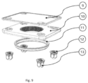
- Reference numeral 9 indicates the sealing between the flange 10 itself and the equipment that is to be made mobile.
- Under the flange 10 a pivot wiper seal 11 is mounted.
- the flange is attached by means of hygienic nuts 13, on which seals 12 are arranged.
- the wheel itself is shown in Fig. 10 . It is mounted on the castor wheel structure by means of a wheel bearing joint 16, which is attached with a shaft locking ring 17. Here the wheel 18 is shown from both the outside and the inside.
- the choice of bearing for the structure is of great importance in terms of price and use.
- the wheel bearings are of crucial importance to the manoeuvrability and hence the quality of the castor wheel.
- different other requirements apply to the wheels under waste collection containers, hospital beds and for instance shopping trolleys, and quite different requirements to wheels used for transporting heavy cargoes at a factory, and it is of crucial importance that the choice of bearing is adapted to the relevant use.
- the structure is advantageously provided with electrically conductive wheels with a discharging resistor that is lower than 10,000 ohm.
- electrically conductive wheels with a discharging resistor that is lower than 10,000 ohm.
- Fig. 11 shows a cross section with sections in magnification of the mounted wheel
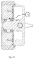
- Fig. 12 shows how the bearings 19 are inserted in the outer bearing ring 16.
- a ring bead is provided, which in cross section is shaped as a wedge with barb, on the outer side of the bearing ring 16.
- the bead creates a track, which, as the bearing ring 16 is squeezed in, is formed on the inner side of the wheel hub.
- the bead functions as a barb, which ensures that the parts cannot be separated easily.
- bearing should be adapted to the relevant intended use.
- two deep groove ball bearings are used, ensuring the best relationship between rolling friction and carrying capacity.
- Angular contact ball bearings, roller bearings or sliding bearings can also be used. Angular contact ball bearings and roller bearings are used when special requirements apply, while the sliding bearing will be the cheapest solution, which can be used for equipment that is to be moved at low speed and over short distances.
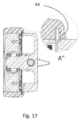
- the covering of the wheel hub has a double function. It functions both as tyre and seal. As shown at detail A", one side of the covering is provided with a tongue that extends towards the wheel house and provides protection against moisture and other contamination. It must be ensured that the abutment pressure is so low that the roller friction is not substantially affected and still so strong that the tightness is ensured.
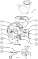
- Fig. 14 shows the basic parts of a wheel house 28 with brake function in the exploded view.
- the wheel index pawl 29 with spring 20 is mounted in the wheel house together with a pull-out auxiliary spring 34.
- the wheel index stud 24 is fastened with a screw 25.
- an index pivot spring 40 is led over an index pivot arm 39, which is guided down into the leg of the wheel house until it catches a pin on the camshaft 33.
- the locking plate 30 is fastened with a screw 31 to retain the index pivot arm 39 and the camshaft 33 in the house.
- a pointed screw 21 is screwed into a limit stop 22, which is put in position in the wheel house 28.
- a pedal/shaft gasket 26 is led over a pedal/shaft structure 27.
- the two parts that the pedal/shaft structure consist of, i.e. a pedal and a shaft, are for instance assembled with a multiple-spline socket and Loctite ® , but it is possible to use other assembly methods such as cone and pin.
- the pedal/shaft structure 27 is pushed into the wheel house until the shaft's multiple-spline socket has caught the limit stop and the camshaft 33.
- the top part which is the turntable, on which the spindle or the flange is to be mounted.
- the parts of the turntable are illustrated in Fig. 15 .
- the parts are placed on top of each other.
- a needle bearing 37 is placed and on top of that an index pivot disc 38 and subsequently yet another needle bearing, and above this a pivot friction disc 36 is placed.
- the camshaft structure is screwed onto the the uppermost part of the wheel house by means of a countersunk screw 35.
- Fig. 16 shows the individual main parts of the structure.
- a spindle structure 1 or a flange structure 2 can be mounted and possibly retained with a thread lock, such as Loctite ® , which is added where indicated by the large arrow.
- a thread lock such as Loctite ®
- the assembled castor wheel structure has the following functions.
- the brake can be activated by pressing on the long end of the crank 27.
- Fig. 17 shows the crank in the unlocked position. During the first part of the movement, there will be slight springy resistance, and thereafter a small, more pronounced resistance will be felt, and lastly a perception of locking in a notch. How to achieve the special perception of the individual steps is described in detail below.
- Fig. 18 shows the crank in the locked position. During the first part of the movement, there is a slight resistance and thereafter a perception of a springy jump backwards. Achieving the special perception of the individual steps of deactivation will also be described in detail below together with an explanation of how the brake actually works, and how it can resist intense impacts from all sides without slipping or letting go.
- Fig. 19 where the function of the limit stop 22 will be explained.
- the pedal On braking the pedal is activated by a person, who presses down the long crank with a foot. The movement and the force are transferred through the shaft to the limit stop. This force can be quite powerful, and the structure is designed to an expected pressure of 2000 N.
- the limit stop 22 is therefore provided with a multiple-split socket, which can transfer the intense forces to the wheel house.
- the limit stop has an additional function, namely locking of the pedal shaft in axial direction, which is effected by the pointed screw after assembly.
- a pressure on the long crank will cause the pedal/shaft to carry out a rotational movement (A) clockwise, and the top pawl of the camshaft to press (B) against the index arm, which turns (C) about the index stud 24 and removes the pressure from the index wheel pawl 29.
- the pawl is pressed (D) by the spring against the index wheel and will, when it is possible, find its way into a notch and lock the wheel.
- the rotational movement constantly gets resistance (E) from the index spring arm 32 behind the index arm 23, and this gives the user a perception of locking something. If the help exceeds the resistance by pressing out the index wheel pawl 29, the pawl of the camshaft only functions as lock when the brake is deactivated.
- a pressure on the short crank will cause the pedal/shaft to carry out a rotational movement (A) anti-clockwise, and the pawl of the camshaft to press (B) against the index arm, which turns (C) about the index stud 24 and puts pressure (D) on the index wheel pal 29, which is pressed out by the index wheel.
- the rotational movement constantly gets help (E) from the index spring arm 32 behind the index arm 23. If the help exceeds the resistance by pressing out the index wheel pawl 29, the pawl of the camshaft will only function as lock when the brake is deactivated.
- the spring arm 32 turns about the camshaft and the pedal/shaft without any other connection that the shaft being used as pivot shaft.
- the spring 34 presses against the arm at one end and thus transfers a corresponding pressure to the other end against the index arm 23, which again presses on the index wheel pal 29.
- Fig. 23 shows that the pedal for activation of the lock by means of the index pivot arm 39 rotates clockwise and thereby the camshaft 33 also rotates clockwise, and the pawls will seek to slot into place, and when they do, both the pivot and wheel will be locked.
- the spring 40 has given the movement resistance and has been tensioned until the end position, where the spring retains the pedal in the outer position clockwise.
- the stop limit is configured to be so robust that it can withstand full load from the user.
- the pedal rotates, as shown in Fig. 24 , anti-clockwise and forces out first the pivot pawl and then the wheel pawl.
- the spring facilitates the movement.
- the robust configuration of the stop limit ensures that full load from the user can be withstood.
- the spindle solution requires a seal 1) between equipment and spindle case, 2) between spindle and pivot/spindle cap, 3) between pivot/spindle cap and turntable of the wheel house, 4) between wheel and wheel house and 5) between brake shaft and wheel house.
- the spindle solution requires a seal 1) between equipment and flange, 2) between flange and nuts, 3) between flange and turntable of the wheel house, 4) between wheel and wheel house and 5) between brake shaft and wheel house.
- the preferred choice of sealing material is NBR (NNF-85), but for instance silicone can also be used. Seals and their preferred configurations are described in the following.
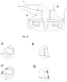
- Fig. 25 shows a section of a joint between a spindle 5 and the upper end of the castor wheel house with the sealing ring 6 between the spindle and the pivot/spindle cap (shown in magnification in sections B and B'), and the pivot sealing between the pivot/spindle cap and the turntable of the wheel house (shown in magnification in section A).
- Fig. 26 shows a sealing ring 41, which is used when the structure is to be used without brake arm. This seal thus provides sealing between the castor wheel house 28 and an inserted plug 42, and the sealing principle is shown in magnification in details C and C'
- the seal between the wheel 18 and the wheel house 28 is illustrated in Fig. 28 and is, as mentioned above, secured by means of the coating or tyre 43, which is configured integrally with a tongue, here designated with reference numeral 44.
- This coating may also be made of massive NBR, but in the preferred embodiment it is made of non-marking blue polyurethane.
- the coating or the wheel path 43 can also be manufactured of polyurethane with thread-guards (electrically conductive) or of thermoplastic rubber. It is common for the types that they provide the necessary sealing effect without the friction between the tongue 44 and the wheel house 28 becoming too large.
- Detail E in Fig. 28 shows the configuration of the transition between the wheel rim 45 and the hub cap 46, which keeps a spacer 47 in place.
- the wheel rim 45 is preferably manufactured of polyamide (PA6), but can for instance also be manufactured of corrosion-proof 304 steel or electrically conductive polyamide or polypropylene. Electrically conductive materials are selected if discharge for avoiding static electricity is desired.
- wheel house contains functionalities, which are not used in some cases, but for practical and aesthetic considerations, it may be expedient to use the same house and wheels for all castor wheel structures according to the invention.
Landscapes
- Engineering & Computer Science (AREA)
- Mechanical Engineering (AREA)
- Braking Arrangements (AREA)
- Handcart (AREA)
- Legs For Furniture In General (AREA)
- Apparatus For Disinfection Or Sterilisation (AREA)
Description
- The present invention relates to a castor wheel structure according to the preamble of claim 1.
- Castor wheels are also known as machine wheels and are wheels that in addition to the wheel part itself comprise a mounting element, which is typically standardised. Thus, the wheel is a building part, which can generally be replaced by other similar wheels. There are basically two types of castor wheels. One has a turntable, so that the wheel is allowed to oscillate freely, and it can be equipped with a brake both on the wheel itself and on the turntable, and as regards the second type, the shaft of the castor wheel is fixably mounted, and it can also be equipped with a brake on the wheel itself.
- Generally, castor wheels are used for increasing the mobility of many different forms of objects, such as various forms of machines, for instance mixers, fillers, and machines and apparatuses with functions that are to be used in several locations as well as conveyor belts, racks and work tables. Other fields, in which castor wheels are frequently used are for instance for movable hospital beds, trolleys, vacuum cleaners as well as other mobile apparatuses.
- The castor wheel is a rotatable wheel (not a guide wheel), which is typically used for manual movement of equipment by pushing it at a speed that usually does not exceed the walking pace, and the castor wheel is typically not used for equipment in continuous movement.
- Common to existing castor wheels is that they are not suitable for use in areas with particular hygiene requirements, as the moving pairs, which they will inevitably contain, are not protected against the ingress of dirt and germ-filled material, which means that existing wheels are very difficult to clean completely and will therefore always constitute a risk of contamination in for instance hospital environments and laboratories or in the food industry, where there is also focus on the pathways and habitats of microorganisms.
- In
US 2015/0258850 a castor wheel structure is described, comprising a wheel part and a castor wheel house, on which a transition element can be mounted, which again can be mounted on equipment, such as hospital equipment, which is to be made mobile, which wheel part is unilaterally suspended and arranged about a substantially horizontal shaft on the castor wheel house. The castor wheel structure moreover comprises a seal between the transition element and the upper part of the castor wheel house, which seal is configured with contours that are adapted to the structure and thereby substantially ensure continuous surfaces. - Thus, the object of the present invention is to provide a preferably maintenance-free castor wheel structure, which has a hygienically correct configuration, and which preferably meets the standards that can lead to hygienic approval of the product in accordance with the guidelines of for instance EHEDG, 3-A and USDA.
- The objects mentioned above are obtained by means of a castor wheel structure according to claim 1.
- Thus sealing of the inner part of the structure is obtained, so that exchange of material between the inside and the outside of the castor wheel structure cannot take place. Thereby a maintenance-free structure is obtained, which does not discharge hygienically problematic substances to the environment. Furthermore, by means of the obtained continuous surfaces, it is ensured that the structure can easily be cleaned with the lowest possible risk of accumulation of dirt and deposits on the structure.
- According to claim 2, the seal between the wheel part and the castor wheel house is fixably mounted on either the wheel part or the castor house and has sliding abutment with the other part. It is thus possible to mount the seal on the wheel part and have sliding abutment with the castor house or mount the seal on the castor house and have sliding abutment with the wheel part.
- A preferred embodiment of the invention is characteristic in that the seal between the wheel part and the castor wheel house is formed as a tongue, which is an integral part of a wheel covering. Hereby a simple and functional structure is obtained, with which a few individual parts contribute to ensuring that the objects of the invention are met.
- When the transition element is a spindle structure, it must according to a preferred embodiment be equipped with a sealing ring, which seals between the spindle and a transition piece, which is also equipped with a seal. Hereby the connection with the equipment that is to be made mobile can also be hygienic. However, as will be obvious to a skilled person, it requires that a hygienic seal is also secured at the upper thread, by means of which the spindle structure is attached to the equipment.
- When the transition element is a flange structure, it must according to another preferred embodiment be provided with a seal between the flange itself and the equipment, and under the flange a seal is mounted, which flange is attached by means of nuts with seals placed upon them. In the same manner as above, this ensures that the connection with the equipment that is to be made mobile is hygienic.
- It is advantageous that the seals are configured with surfaces, which provide smooth, soft transitions, and most of the seals are activated and kept in place by being retained with pressure in the tracks and cavities, in which they are mounted. Thus, surfaces are obtained, which are easy to clean and inspect.
- It is also advantageous that all outer surfaces are smooth (Ra of max. 0.8 µ), self-draining and provided with bending radiuses of at least 3.2 mm. This ensures that some of the formal requirements for obtaining hygienic approval are met.
- According to the invention, inner braking of the wheel can be obtained. For this object, the castor wheel structure comprises a brake shaft fitted with a crank, which brake shaft is provided with a seal that ensures sealing between the brake shaft and the castor wheel house.
- It is advantageous that the brake shaft can function, so that it either activates braking of the wheel movement or of the pivot movement or of both movements.
- The braking mentioned above can take place by the brake shaft having connection with a camshaft, which can activate and deactivate a pawl system, which in connection with index plates can lock the wheel movement and/or the pivot movement, respectively.
- Thus, very precise and safe braking of the wheel's movements is obtained. At correct dimensioning, the wheel will as a maximum have to turn or roll a very small distance (for instance 2-4 mm) during activation of the brake, for the braking to be executed.
- According to the invention, it is advantageous that the camshaft actively secures both activation and deactivation of brake systems, which comprise a wheel spring arm and a wheel index arm, by means of a slot-like control of the wheel spring arm and the wheel index arm. This ensures that the brakes will not rub.
- Advantageously, the wheel spring arm and the wheel index arm are provided with pawls for engagement with the index plates and with preferably encompassing springs, which contribute to correct activation of the brake systems, and which contribute to giving the user a suitably tactile feedback when the brake is activated and deactivated.
- In a preferred embodiment, the brake shaft is provided with a mounted solid limit stop, which limits the oscillation both on activation and deactivation of a corresponding brake, and which furthermore ensures that the brake shaft cannot be pulled out. This embodiment ensures that the structure is able to accommodate substantial forces, for instance up to 2000 N, and the brake shaft is kept in place inside the structure.
- The crank can advantageously be provided with a long and a short arm, wherein the long arm is used for activation of a corresponding brake by turning of the shaft
- in clockwise direction, and the short arm is used for deactivation of the brake by turning of the shaft in anti-clockwise direction. Thereby a natural perception as to how the user will have to activate and deactivate the brake is obtained.
- In the preferred embodiments of the invention, the seals are manufactured of NBR or silicone, and the wheel coating, which also functions as seal, is manufactured of a polyurethane material or NBR or thermoplastic rubber.
- It is also advantageous that the wheel house, the spindle, the flange and the brake arm with the shaft are manufactured of corrosion-proof steel 304, which is a suitable material for hygienic structures, which are also subjected to strength requirements.
- The invention will be explained further in the following with reference to the drawing, in which
-
Figs 1 and 4 show various practical configurations of hygienic castor wheel structures according to the present invention, -
Figs 2, 3, 5 and 6 show various practical configurations of hygienic castor wheel structures. -
Fig. 7 shows an example of the individual parts of a castor wheel structure according to the invention, -
Fig. 8 shows an exploded view of the spindle structure according to the invention, -
Fig. 9 shows an exploded view of the flange structure according to the invention -
Fig. 10 shows a view of the wheel itself, -
Fig. 11 illustrates a cross section with sections in magnification of the mounted wheel, -
Fig. 12 shows how bearings are inserted in an outer bearing ring, -
Fig. 13 shows the coating of the wheel hub, -
Fig. 14 shows the basic parts of a wheel house with brake function in an exploded view, -
Fig. 15 shows the parts of the turntable, -
Fig. 16 shows the individual main parts of the structure, -
Fig. 17 shows the crank in the unlocked position, -
Fig. 18 shows the crank in the locked position, -
Fig. 19 shows the limit stop, -
Fig. 20 shows the function at activation of the index arm and the wheel pawl, -
Fig. 21 shows the function at deactivation of the index arm and the wheel pawl, -
Fig. 22 shows the function of the spring arm, -
Fig. 23 shows activation of locking by means of the index pivot arm, -
Fig. 24 shows deactivation of locking by means of the index pivot arm, -
Fig. 25 shows a section of a joint between a spindle and the upper end of the castor wheel house with the sealing ring between the spindle and the pivot/spindle cap shown in magnification in sections B and B', and the pivot sealing between the pivot/spindle cap and the turntable of the wheel house shown in magnification in section A, -
Fig. 26 shows a sealing structure, which is used when the castor wheel structure is to be used without brake arm, -
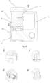
Fig. 27 shows in detail D a sealing structure, which is to be used when a brake arm is mounted, and moreover in section H, a seal between the flange and the equipment is shown, and the pivot wiper seal is shown in section G, and -
Fig. 28 shows in detail E the configuration of the transition between wheel rim and hub cap. -
Figs 1-6 show various practical configurations of castor wheel structures, wherefigs 1 and 4 are castor wheel structures according to the present invention.Figs 1-3 show embodiments with spindle attachment, andFigs 4-6 show embodiments with flange attachment.Figs 1 and 4 show castor wheel structures with brake,Figs 2 and 5 show structures without brake and with pivotally suspended wheels, andFigs 3 and 6 show structures with castor wheels that cannot turn. It is not possible to tell the difference from the outside between the two types inFigs 2 and 5 and inFigs 3 and 6 , respectively, but the difference is that the swing or pivot movement is locked in the latter type. -
Fig. 7 shows an example of a castor wheel structure according to the invention. The castor wheel structure consists of the following parts: A spindle structure 1 or a flange structure 2 and a castor wheel structure 3. Spindle or flange is selected depending on how the castor wheel structure is desired to be attached. The spindle 1 offers the possibility of height adjustment, but otherwise the function is the same regardless of the attachment method selected. Both the spindle and the flange structure is configured as hygienic elements, and the spindle can be provided with a cover, so there is no free thread. All surfaces have a Ra of maximum 0.8 µ in the shown embodiment. - In
Fig. 8 , the spindle structure with the spindle 5 itself is shown in an exploded view.Reference numeral 4 indicates a case, and by reference numeral 6, a sealing ring is shown, which seals between the spindle 5 and a transition piece 7, which is also provided with apivot seal 8. The transition piece is attached with a thread to the spindle, and the thread should preferably be secured against loosening by means of a form of thread security, such as Loctite®. - In
Fig. 9 ., the flange structure is shown in an exploded view.Reference numeral 9 indicates the sealing between theflange 10 itself and the equipment that is to be made mobile. Under theflange 10, apivot wiper seal 11 is mounted. The flange is attached by means ofhygienic nuts 13, on which seals 12 are arranged. - The wheel itself is shown in
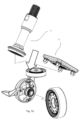
Fig. 10 . It is mounted on the castor wheel structure by means of a wheel bearing joint 16, which is attached with a shaft locking ring 17. Here thewheel 18 is shown from both the outside and the inside. The choice of bearing for the structure is of great importance in terms of price and use. In addition to the wheel path, the wheel diameter and the pivot bearing, the wheel bearings are of crucial importance to the manoeuvrability and hence the quality of the castor wheel. There are obviously different requirements for wheels to be used as wheels for furniture in the home and those that are to be used in commercial businesses. Likewise, different other requirements apply to the wheels under waste collection containers, hospital beds and for instance shopping trolleys, and quite different requirements to wheels used for transporting heavy cargoes at a factory, and it is of crucial importance that the choice of bearing is adapted to the relevant use. - To be able to avoid static electricity, which may cause discomfort for the users when synthetic material is charged by friction, and the charged tension cannot be discharged, so the discharge takes place through the user, the structure is advantageously provided with electrically conductive wheels with a discharging resistor that is lower than 10,000 ohm. Hereby it is also ensured that the risk of explosion, for instance as a consequence of ignition of explosive gases and explosive dust, can be minimized.
-
Fig. 11 shows a cross section with sections in magnification of the mounted wheel, andFig. 12 shows how thebearings 19 are inserted in theouter bearing ring 16. At detail B", it appears that a ring bead is provided, which in cross section is shaped as a wedge with barb, on the outer side of thebearing ring 16. The bead creates a track, which, as the bearingring 16 is squeezed in, is formed on the inner side of the wheel hub. Hereafter the bead functions as a barb, which ensures that the parts cannot be separated easily. - As stated above, the choice of bearing should be adapted to the relevant intended use. In the preferred embodiment, two deep groove ball bearings are used, ensuring the best relationship between rolling friction and carrying capacity. Angular contact ball bearings, roller bearings or sliding bearings can also be used. Angular contact ball bearings and roller bearings are used when special requirements apply, while the sliding bearing will be the cheapest solution, which can be used for equipment that is to be moved at low speed and over short distances.
- As appears from
Fig. 13 , the covering of the wheel hub has a double function. It functions both as tyre and seal. As shown at detail A", one side of the covering is provided with a tongue that extends towards the wheel house and provides protection against moisture and other contamination. It must be ensured that the abutment pressure is so low that the roller friction is not substantially affected and still so strong that the tightness is ensured. -
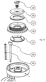
Fig. 14 shows the basic parts of awheel house 28 with brake function in the exploded view. At assembly of the parts of thewheel house 28, the parts are assembled in groups in the following manner: Thewheel index pawl 29 withspring 20 is mounted in the wheel house together with a pull-outauxiliary spring 34. Hereafter the group that consists of acamshaft 33 with two flat arms, respectively, thewheel spring arm 32 and thewheel index arm 23, with awheel index stud 24 inserted. All parts are placed in thewheel house 28. Hereafter thewheel index stud 24 is fastened with ascrew 25. Then anindex pivot spring 40 is led over anindex pivot arm 39, which is guided down into the leg of the wheel house until it catches a pin on thecamshaft 33. Then the lockingplate 30 is fastened with ascrew 31 to retain theindex pivot arm 39 and thecamshaft 33 in the house. Hereafter apointed screw 21 is screwed into alimit stop 22, which is put in position in thewheel house 28. Then a pedal/shaft gasket 26 is led over a pedal/shaft structure 27. The two parts that the pedal/shaft structure consist of, i.e. a pedal and a shaft, are for instance assembled with a multiple-spline socket and Loctite®, but it is possible to use other assembly methods such as cone and pin. Hereafter the pedal/shaft structure 27 is pushed into the wheel house until the shaft's multiple-spline socket has caught the limit stop and thecamshaft 33. Hereafter the top part remains, which is the turntable, on which the spindle or the flange is to be mounted. The parts of the turntable are illustrated inFig. 15 . Before mounting the turntable, the parts are placed on top of each other. At the bottom aneedle bearing 37 is placed and on top of that anindex pivot disc 38 and subsequently yet another needle bearing, and above this apivot friction disc 36 is placed. When the other groups are mounted in the wheel house, the camshaft structure is screwed onto the the uppermost part of the wheel house by means of a countersunkscrew 35. -
Fig. 16 shows the individual main parts of the structure. On top of the assembled wheel house structure, either a spindle structure 1 or a flange structure 2 can be mounted and possibly retained with a thread lock, such as Loctite®, which is added where indicated by the large arrow. When the wheel structure has been clicked on, the castor wheel structure is ready for use. - The assembled castor wheel structure has the following functions. The brake can be activated by pressing on the long end of the
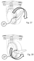
crank 27.Fig. 17 shows the crank in the unlocked position. During the first part of the movement, there will be slight springy resistance, and thereafter a small, more pronounced resistance will be felt, and lastly a perception of locking in a notch. How to achieve the special perception of the individual steps is described in detail below. - Deactivation of the brake is obtained by pressing the short part of the crank.
Fig. 18 shows the crank in the locked position. During the first part of the movement, there is a slight resistance and thereafter a perception of a springy jump backwards. Achieving the special perception of the individual steps of deactivation will also be described in detail below together with an explanation of how the brake actually works, and how it can resist intense impacts from all sides without slipping or letting go. - As regards both wheel and pivot brakes, there is a possibility that they can lock rotation with a pawl between index teeth and index holes in the wheel when they are activated. If they do not do that directly, a very small shift will cause the pawl to slot into place and lock. The brake backlash corresponds to +/-1/2% or +/- 0.57 degrees before complete locking. When the brake is deactivated, the pawl is pulled out with the rotational movement, but not at the first part of the movement as the wheel pawl is helped to be pulled out. This procedure will also be explained in the following.
- Reference is now made to
Fig. 19 , where the function of thelimit stop 22 will be explained. On braking the pedal is activated by a person, who presses down the long crank with a foot. The movement and the force are transferred through the shaft to the limit stop. This force can be quite powerful, and the structure is designed to an expected pressure of 2000 N. Thelimit stop 22 is therefore provided with a multiple-split socket, which can transfer the intense forces to the wheel house. The limit stop has an additional function, namely locking of the pedal shaft in axial direction, which is effected by the pointed screw after assembly. - Referring to
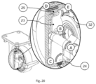
Fig. 20 (activation) andFig. 21 (deactivation), the function of theindex arm 23 and thewheel pawl 29 will be explained below. At activation, a pressure on the long crank will cause the pedal/shaft to carry out a rotational movement (A) clockwise, and the top pawl of the camshaft to press (B) against the index arm, which turns (C) about theindex stud 24 and removes the pressure from theindex wheel pawl 29. The pawl is pressed (D) by the spring against the index wheel and will, when it is possible, find its way into a notch and lock the wheel. The rotational movement constantly gets resistance (E) from theindex spring arm 32 behind theindex arm 23, and this gives the user a perception of locking something. If the help exceeds the resistance by pressing out theindex wheel pawl 29, the pawl of the camshaft only functions as lock when the brake is deactivated. - As illustrated in
Fig. 21 , a pressure on the short crank will cause the pedal/shaft to carry out a rotational movement (A) anti-clockwise, and the pawl of the camshaft to press (B) against the index arm, which turns (C) about theindex stud 24 and puts pressure (D) on theindex wheel pal 29, which is pressed out by the index wheel. The rotational movement constantly gets help (E) from theindex spring arm 32 behind theindex arm 23. If the help exceeds the resistance by pressing out theindex wheel pawl 29, the pawl of the camshaft will only function as lock when the brake is deactivated. - Reference is now made to
Fig. 22 , where the function of thespring arm 32 will be explained. Thespring arm 32 turns about the camshaft and the pedal/shaft without any other connection that the shaft being used as pivot shaft. Thespring 34 presses against the arm at one end and thus transfers a corresponding pressure to the other end against theindex arm 23, which again presses on theindex wheel pal 29. -
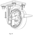
Fig. 23 shows that the pedal for activation of the lock by means of theindex pivot arm 39 rotates clockwise and thereby thecamshaft 33 also rotates clockwise, and the pawls will seek to slot into place, and when they do, both the pivot and wheel will be locked. Thespring 40 has given the movement resistance and has been tensioned until the end position, where the spring retains the pedal in the outer position clockwise. The stop limit is configured to be so robust that it can withstand full load from the user. - For deactivation of locking by means of the index pivot arm, the pedal rotates, as shown in
Fig. 24 , anti-clockwise and forces out first the pivot pawl and then the wheel pawl. The spring facilitates the movement. As outlined above, the robust configuration of the stop limit ensures that full load from the user can be withstood. - With the present structure, a hygienic structure with a minimal number of seals can be obtained. The spindle solution requires a seal 1) between equipment and spindle case, 2) between spindle and pivot/spindle cap, 3) between pivot/spindle cap and turntable of the wheel house, 4) between wheel and wheel house and 5) between brake shaft and wheel house. The spindle solution requires a seal 1) between equipment and flange, 2) between flange and nuts, 3) between flange and turntable of the wheel house, 4) between wheel and wheel house and 5) between brake shaft and wheel house. The preferred choice of sealing material is NBR (NNF-85), but for instance silicone can also be used. Seals and their preferred configurations are described in the following.
-
Fig. 25 shows a section of a joint between a spindle 5 and the upper end of the castor wheel house with the sealing ring 6 between the spindle and the pivot/spindle cap (shown in magnification in sections B and B'), and the pivot sealing between the pivot/spindle cap and the turntable of the wheel house (shown in magnification in section A). By reducing the distance between the faces and cavities, in which the sealing rings are arranged, to be suitably smaller than the size of the sealing ring, it is, as appears, obtained that the seals are under constant and controlled pressure (shown in broad arrows in A' and B'). In this way, the desired compression and hence the desired sealing effect is obtained. The outer surface is out of consideration for hygiene/easy cleaning configured with a view to providing the best possible protection against germ accumulation in the sealing structure. -
Fig. 26 shows a sealing ring 41, which is used when the structure is to be used without brake arm. This seal thus provides sealing between thecastor wheel house 28 and an inserted plug 42, and the sealing principle is shown in magnification in details C and C' - When a brake arm is used, it must be sealed as shown in details D and D' from
Fig. 27 . Here the sealing 9 is also indicated (see also sections H and H') between theflange 10 and the equipment that is to be made mobile, and the pivot wiper seal 11 (see also sections G and G'). - The seal between the
wheel 18 and thewheel house 28 is illustrated inFig. 28 and is, as mentioned above, secured by means of the coating ortyre 43, which is configured integrally with a tongue, here designated withreference numeral 44. This coating may also be made of massive NBR, but in the preferred embodiment it is made of non-marking blue polyurethane. The coating or thewheel path 43 can also be manufactured of polyurethane with thread-guards (electrically conductive) or of thermoplastic rubber. It is common for the types that they provide the necessary sealing effect without the friction between thetongue 44 and thewheel house 28 becoming too large. - Detail E in
Fig. 28 shows the configuration of the transition between thewheel rim 45 and thehub cap 46, which keeps aspacer 47 in place. The wheel rim 45 is preferably manufactured of polyamide (PA6), but can for instance also be manufactured of corrosion-proof 304 steel or electrically conductive polyamide or polypropylene. Electrically conductive materials are selected if discharge for avoiding static electricity is desired. - As appears from the above, it is advantageous that all seals are made specifically for such use. Thus the possibility is obtained of having completely smooth surfaces that are easy to wash and inspect and which minimize the risk of accumulation of dirt.
- It should be understood that here the invention is configured and described to reflect that it will normally be used as a standard element, which can be directly mounted on various types of equipment. However, it should be understood that the invention can also be integrated with the equipment in such a manner that transition elements are avoided without being outside the scope of the invention.
- It should also be understood that it is not necessary that the wheel house contains functionalities, which are not used in some cases, but for practical and aesthetic considerations, it may be expedient to use the same house and wheels for all castor wheel structures according to the invention.
-
- 1 Spindle structure
- 2 Flange structure
- 3 Castor wheel structure
- 4 Case
- 5 Spindle
- 6 Sealing ring
- 7 Transition piece
- 8 Pivot sealing
- 9 Flange/equipment sealing
- 10 Flange
- 11 Pivot wiper seal
- 12 Sealing for hygienic nut
- 13 Hygienic nut
- 16 Wheel bearing joint
- 17 Shaft locking ring
- 18 Wheel
- 19 Bearings
- 20 Spring for wheel index pawl
- 21 Pointed screw
- 22 Limit stop
- 23 Wheel index arm
- 24 Wheel index stud
- 25 Inner hexagon-headed screw
- 26 Pedal-shaft gasket
- 27 Brake pedal
- 27a Brake shaft
- 28 Wheel house
- 29 Wheel index plate
- 30 Locking plate
- 31 Inner hexagon-headed screw
- 32 Wheel spring arm
- 33 Camshaft
- 34 Pull-out auxiliary spring
- 35 Countersunk screw
- 36 Pivot friction disc
- 37 Needle roller bearing
- 38 Index pivot disc
- 39 Index pivot arm
- 40 Index pivot spring
- 41 Sealing ring
- 42 Plug
- 43 Wheel covering (tyres)
- 44 Sealing tongue
- 45 Wheel rim
- 46 Hub cap
- 47 Spacer
Claims (16)
- A castor wheel structure, comprising a wheel part (18) and a castor wheel house (28), on which a transition element can be mounted, such as a spindle structure (1) or a flange structure (2), which again can be mounted on equipment that is to be made mobile, which wheel part (18) is unilaterally suspended and arranged about a substantially horizontal shaft on the castor wheel house (28), which castor wheel structure also comprises a seal (8, 11) to be arranged between the transition element (1 or 2) and the upper part of the castor wheel house (28), which seal (8, 11) is configured with contours which substantially ensure continuous surfaces characterized in that the castor wheel structure further comprises a seal (44) between the wheel part (18) and the castor wheel house (28), which seal is configured with contours which substantially ensure continuous surfaces, wherein the castor wheel structure comprises a brake shaft (27a) fitted with a crank (27), which brake shaft (27a) is provided with a seal that ensures sealing between the brake shaft (27a) and the castor wheel house (28).
- A castor wheel according to claim 1, characterized in that the seal between the wheel part (18) and the castor wheel house (28) is fixably mounted on either the wheel part or the castor house and has sliding abutment with the other part.
- A castor wheel structure according to claim 1 or 2, characterized in that the seal between the wheel part (18) and the castor wheel house (28) is configured as a tongue (44), which is an integral part of a wheel covering (43).
- A castor wheel structure according to any of claims 1 to 3, characterized in that the castor wheel structure includes the transition element and wherein the transition element is a spindle (5), and it is equipped with a sealing ring (6), which provides sealing between the spindle (5) and a transition piece (7), which is also equipped with a sealing ring (8), which sealing ring corresponds to the seal between the transition element and the upper part of the castor wheel house (28).
- A castor wheel structure according to any of claims 1 to 3, characterized in that the castor wheel structure includes the transition element and wherein the transition element is a flange structure (2), and it is provided with a seal (9) between the flange (10) itself and the equipment, and under the flange (10) the seal (11) between the transition element and the upper part of the castor wheel house is mounted, which flange is attached by means of nuts (13) with seals (12) placed upon them.
- A castor wheel structure according to any of the preceding claims, characterized in that the seals are configured with surfaces, which provide smooth, soft transitions, and most of the seals are activated and kept in place by being retained with pressure in the tracks and cavities, in which they are mounted.
- A castor wheel structure according to any of the preceding claims, characterized in that all outer surfaces are smooth (Ra of max. 0.8 m), self- draining and provided with bending radiuses of at least 3.2 mm.
- A castor wheel structure according to anyone of the preceding claims, characterized in that the brake shaft (27a) can function, so that it either activates braking of the wheel movement or of the pivot movement or of both movements.
- A castor wheel structure according to anyone of the preceding claims, characterized in the that the brake shaft (27a) has connection with a camshaft (33), which can activate and deactivate a pawl system, which in connection with index plates can lock the wheel movement and/or the pivot movement, respectively.
- A castor wheel structure according to claim 9, characterized in that the camshaft (33) actively ensures both activation and deactivation of brake systems, which comprise a wheel spring arm (32) and a wheel index arm (23), by means of a slot-like control of the wheel spring arm (32) and the wheel index arm (23).
- A castor wheel structure according to claim 10, characterized in that the wheel spring arm (32) and the wheel index arm (23) are provided with pawls for engagement with the index plates and with preferably encompassing springs, which contribute to correct activation of the brake systems, and which contribute to giving the user a suitably tactile feedback when the brake is activated and deactivated.
- A castor wheel structure according to anyone of the preceding claims, characterized in that the brake shaft (27a) is provided with a mounted solid limit stop (22), which limits the oscillation both on activation and deactivation of a corresponding brake, and which further ensures that the brake shaft (27a) cannot be pulled out.
- A castor wheel structure according to anyone of the preceding claims, characterized in that the crank (27) is provided with a long and a short arm, wherein the long arm is used for activation of a corresponding brake by turning of the shaft (27a) in clockwise direction, and the short arm is used for deactivation of the brake by turning of the shaft (27a) in anti-clockwise direction.
- A castor wheel structure according to any of the preceding claims, characterized in that the castor wheel structure comprises wheel and pivot brakes, and in that both wheel and pivot brakes lock rotation with a pawl between index teeth and index holes in the wheel when they are activated.
- A castor wheel structure according to any of the preceding claims, characterized in that the seals are manufactured of NBR or silicone, and the wheel coating, which also functions as seal, is manufactured of a polyurethane material or NBR.
- A castor wheel structure according to any of the preceding claims, characterized in that the wheel house, the spindle, the flange and the brake arm with the shaft (27a) are manufactured of corrosion-proof steel 304.
Applications Claiming Priority (2)
| Application Number | Priority Date | Filing Date | Title |
|---|---|---|---|
| DKPA201870140A DK179906B1 (en) | 2018-03-02 | 2018-03-02 | Castor Wheel |
| PCT/DK2019/050077 WO2019166070A1 (en) | 2018-03-02 | 2019-03-01 | A castor wheel |
Publications (4)
| Publication Number | Publication Date |
|---|---|
| EP3758955A1 EP3758955A1 (en) | 2021-01-06 |
| EP3758955A4 EP3758955A4 (en) | 2021-11-24 |
| EP3758955B1 true EP3758955B1 (en) | 2025-05-07 |
| EP3758955C0 EP3758955C0 (en) | 2025-05-07 |
Family
ID=67804840
Family Applications (1)
| Application Number | Title | Priority Date | Filing Date |
|---|---|---|---|
| EP19761052.0A Active EP3758955B1 (en) | 2018-03-02 | 2019-03-01 | A castor wheel |
Country Status (10)
| Country | Link |
|---|---|
| US (1) | US11413903B2 (en) |
| EP (1) | EP3758955B1 (en) |
| JP (1) | JP7431164B2 (en) |
| CN (1) | CN111801230B (en) |
| AU (1) | AU2019228200B2 (en) |
| CA (1) | CA3088575A1 (en) |
| DK (1) | DK179906B1 (en) |
| ES (1) | ES3029648T3 (en) |
| NZ (1) | NZ766854A (en) |
| WO (1) | WO2019166070A1 (en) |
Families Citing this family (3)
| Publication number | Priority date | Publication date | Assignee | Title |
|---|---|---|---|---|
| USD953851S1 (en) * | 2020-02-03 | 2022-06-07 | Ngi A/S | Caster wheel |
| GB2608761B (en) * | 2020-04-13 | 2024-03-06 | Sharkninja Operating Llc | Caster locking arrangement and surface cleaning device implementing same |
| US12330846B2 (en) * | 2020-07-29 | 2025-06-17 | The Merchant Of Tennis, Inc. | Storage container with lid dolly |
Family Cites Families (30)
| Publication number | Priority date | Publication date | Assignee | Title |
|---|---|---|---|---|
| US2617698A (en) * | 1949-03-19 | 1952-11-11 | Aerol Co Inc | Sealed wheel |
| US3177516A (en) * | 1961-05-25 | 1965-04-13 | Shepherd Casters Inc | Tilted axle caster |
| DE1525099A1 (en) * | 1965-02-15 | 1969-08-28 | Artur Fischer | Split hub with crank |
| GB1403190A (en) * | 1971-11-26 | 1975-08-28 | Kenrick & Sons Ltd | Castors |
| US3928888A (en) * | 1974-08-30 | 1975-12-30 | Lapham Engineering Inc | Interchangeable caster with inclined axle and lint protection means |
| US4113328A (en) * | 1977-08-22 | 1978-09-12 | C. L. Frost & Son, Inc. | Wheel bearing assembly with plastic bearing seals |
| US4184227A (en) * | 1978-06-22 | 1980-01-22 | Propst Paul L | Sanitary caster |
| FR2637039B1 (en) * | 1988-09-28 | 1991-04-26 | Villemin Michel | SEALING DEVICE, PARTICULARLY FOR CASTERS |
| JPH0628369Y2 (en) * | 1989-05-08 | 1994-08-03 | 株式会社オーキン | Carrier |
| US5002163A (en) * | 1989-08-11 | 1991-03-26 | Standex International Corporation | Friction wheel brake |
| JPH03125603A (en) * | 1989-10-12 | 1991-05-29 | Ace Rageeji Kk | Caster |
| DE9001283U1 (en) * | 1990-02-05 | 1990-06-13 | AS Handelsgesellschaft für Rollentechnik mbH, 5632 Wermelskirchen | Castor, especially swivel castor, for furniture, appliances or the like. |
| US5461753A (en) * | 1993-10-22 | 1995-10-31 | Albion Industries, Inc. | Seal for swivel caster assembly |
| US5634240A (en) * | 1994-01-14 | 1997-06-03 | Master Manufacturing, Inc. | Roller components for atachment to an article of luggage |
| US5479677A (en) * | 1994-09-07 | 1996-01-02 | Chong; Ping-Feng | Caster device |
| US5518322A (en) * | 1994-12-30 | 1996-05-21 | Hicks; Jimmy L. | Shopping cart wheel with roller/ball bearings |
| DE19720574C1 (en) * | 1997-05-16 | 1999-01-21 | Steinco Paul Vom Stein Gmbh | Steering castor for furniture |
| JP2001301405A (en) | 2000-04-21 | 2001-10-31 | Nissho:Kk | Support structure of caster |
| US7284966B2 (en) * | 2003-10-01 | 2007-10-23 | Agency For Science, Technology & Research | Micro-pump |
| US7143472B2 (en) * | 2003-10-10 | 2006-12-05 | Gary Dwayne Hicks | Caster thread guard and caster assembly |
| CN201120831Y (en) * | 2007-08-27 | 2008-09-24 | 上海林春万向轮制造有限公司 | Plastic rack complete brake two-wheel medical truckle |
| JP3140092U (en) * | 2007-12-20 | 2008-03-13 | 聖佰企業有限公司 | A caster device that can simultaneously limit rotation and direction change |
| CN101927661B (en) * | 2010-08-23 | 2015-10-21 | 黄锡全 | Bidirectional brake caster |
| CN202480773U (en) * | 2011-10-12 | 2012-10-10 | 刘登临 | Improved caster brake structure |
| DE202012100345U1 (en) * | 2012-02-02 | 2012-03-06 | Sunny Castors Co., Ltd. | Drag reel |
| US9168689B2 (en) * | 2012-06-08 | 2015-10-27 | Ngs Capital Management, Llc | Durable, quiet hubless caster technology |
| JP2014077527A (en) * | 2012-10-12 | 2014-05-01 | Ntn Corp | Wheel bearing device and manufacturing method thereof |
| BR102014005702B1 (en) * | 2014-03-12 | 2021-01-19 | Roberto Nicola Schioppa | improvements introduced in armored hospital casters |
| US9387723B2 (en) | 2014-06-27 | 2016-07-12 | Shepherd Caster Llc | Swivel lock for a caster |
| US9592703B1 (en) * | 2015-09-14 | 2017-03-14 | Heinzen Llc | Height adjustable support for food processing equipment |
-
2018
- 2018-03-02 DK DKPA201870140A patent/DK179906B1/en active IP Right Grant
-
2019
- 2019-03-01 AU AU2019228200A patent/AU2019228200B2/en active Active
- 2019-03-01 US US16/966,602 patent/US11413903B2/en active Active
- 2019-03-01 JP JP2020543877A patent/JP7431164B2/en active Active
- 2019-03-01 WO PCT/DK2019/050077 patent/WO2019166070A1/en not_active Ceased
- 2019-03-01 CN CN201980016629.6A patent/CN111801230B/en active Active
- 2019-03-01 ES ES19761052T patent/ES3029648T3/en active Active
- 2019-03-01 EP EP19761052.0A patent/EP3758955B1/en active Active
- 2019-03-01 NZ NZ766854A patent/NZ766854A/en unknown
- 2019-03-01 CA CA3088575A patent/CA3088575A1/en active Pending
Also Published As
| Publication number | Publication date |
|---|---|
| ES3029648T3 (en) | 2025-06-24 |
| DK179906B1 (en) | 2019-09-18 |
| JP7431164B2 (en) | 2024-02-14 |
| AU2019228200A1 (en) | 2020-09-10 |
| EP3758955A4 (en) | 2021-11-24 |
| NZ766854A (en) | 2026-01-30 |
| EP3758955A1 (en) | 2021-01-06 |
| WO2019166070A1 (en) | 2019-09-06 |
| RU2020132148A (en) | 2022-04-04 |
| CN111801230B (en) | 2024-07-09 |
| CA3088575A1 (en) | 2019-09-06 |
| EP3758955C0 (en) | 2025-05-07 |
| US20210394557A1 (en) | 2021-12-23 |
| DK201870140A1 (en) | 2019-09-18 |
| CN111801230A (en) | 2020-10-20 |
| JP2021514887A (en) | 2021-06-17 |
| AU2019228200B2 (en) | 2024-11-21 |
| US11413903B2 (en) | 2022-08-16 |
Similar Documents
| Publication | Publication Date | Title |
|---|---|---|
| EP3758955B1 (en) | A castor wheel | |
| EP3572239B1 (en) | Caster assembly with brake assembly having low actuation force | |
| US5390393A (en) | Caster with a fouling-resistant bearing cup feature | |
| US20100306962A1 (en) | Hubless Caster Technology | |
| US12240516B2 (en) | Brake operating arrangement | |
| CN203093617U (en) | Caster | |
| CA2686342A1 (en) | Caster with weight transferring tab | |
| JP5254230B2 (en) | Drift conveyor with bearing elements | |
| US4404707A (en) | Castors | |
| EP0793578B1 (en) | A castor | |
| US9925829B2 (en) | Castor with pin-activated brake | |
| RU2787604C2 (en) | Self-orienting wheel | |
| EP0054797A1 (en) | Twin wheeled castor | |
| CN219256937U (en) | Caster combined with light weight and heavy weight | |
| KR200363567Y1 (en) | brake device for a caster | |
| CA1202153A (en) | Cam wheel and caster lock | |
| KR200371230Y1 (en) | a caster | |
| CN202656788U (en) | Large load bearing automatic braking truckle used in elevator | |
| EP0348160A1 (en) | A castor | |
| GB2255715A (en) | "castor convertible into a glide" | |
| CN121019753A (en) | A clutch pressure disc brake device | |
| JP2004084914A5 (en) |
Legal Events
| Date | Code | Title | Description |
|---|---|---|---|
| STAA | Information on the status of an ep patent application or granted ep patent |
Free format text: STATUS: THE INTERNATIONAL PUBLICATION HAS BEEN MADE |
|
| PUAI | Public reference made under article 153(3) epc to a published international application that has entered the european phase |
Free format text: ORIGINAL CODE: 0009012 |
|
| STAA | Information on the status of an ep patent application or granted ep patent |
Free format text: STATUS: REQUEST FOR EXAMINATION WAS MADE |
|
| 17P | Request for examination filed |
Effective date: 20201002 |
|
| AK | Designated contracting states |
Kind code of ref document: A1 Designated state(s): AL AT BE BG CH CY CZ DE DK EE ES FI FR GB GR HR HU IE IS IT LI LT LU LV MC MK MT NL NO PL PT RO RS SE SI SK SM TR |
|
| AX | Request for extension of the european patent |
Extension state: BA ME |
|
| DAV | Request for validation of the european patent (deleted) | ||
| DAX | Request for extension of the european patent (deleted) | ||
| A4 | Supplementary search report drawn up and despatched |
Effective date: 20211025 |
|
| RIC1 | Information provided on ipc code assigned before grant |
Ipc: B60B 33/02 20060101ALI20211019BHEP Ipc: B60B 33/00 20060101AFI20211019BHEP |
|
| STAA | Information on the status of an ep patent application or granted ep patent |
Free format text: STATUS: EXAMINATION IS IN PROGRESS |
|
| 17Q | First examination report despatched |
Effective date: 20230420 |
|
| GRAP | Despatch of communication of intention to grant a patent |
Free format text: ORIGINAL CODE: EPIDOSNIGR1 |
|
| STAA | Information on the status of an ep patent application or granted ep patent |
Free format text: STATUS: GRANT OF PATENT IS INTENDED |
|
| INTG | Intention to grant announced |
Effective date: 20240216 |
|
| GRAJ | Information related to disapproval of communication of intention to grant by the applicant or resumption of examination proceedings by the epo deleted |
Free format text: ORIGINAL CODE: EPIDOSDIGR1 |
|
| STAA | Information on the status of an ep patent application or granted ep patent |
Free format text: STATUS: EXAMINATION IS IN PROGRESS |
|
| INTC | Intention to grant announced (deleted) | ||
| GRAP | Despatch of communication of intention to grant a patent |
Free format text: ORIGINAL CODE: EPIDOSNIGR1 |
|
| STAA | Information on the status of an ep patent application or granted ep patent |
Free format text: STATUS: GRANT OF PATENT IS INTENDED |
|
| INTG | Intention to grant announced |
Effective date: 20241114 |
|
| GRAS | Grant fee paid |
Free format text: ORIGINAL CODE: EPIDOSNIGR3 |
|
| GRAA | (expected) grant |
Free format text: ORIGINAL CODE: 0009210 |
|
| STAA | Information on the status of an ep patent application or granted ep patent |
Free format text: STATUS: THE PATENT HAS BEEN GRANTED |
|
| AK | Designated contracting states |
Kind code of ref document: B1 Designated state(s): AL AT BE BG CH CY CZ DE DK EE ES FI FR GB GR HR HU IE IS IT LI LT LU LV MC MK MT NL NO PL PT RO RS SE SI SK SM TR |
|
| REG | Reference to a national code |
Ref country code: GB Ref legal event code: FG4D |
|
| REG | Reference to a national code |
Ref country code: CH Ref legal event code: EP |
|
| REG | Reference to a national code |
Ref country code: DE Ref legal event code: R096 Ref document number: 602019069646 Country of ref document: DE |
|
| REG | Reference to a national code |
Ref country code: IE Ref legal event code: FG4D |
|
| REG | Reference to a national code |
Ref country code: ES Ref legal event code: FG2A Ref document number: 3029648 Country of ref document: ES Kind code of ref document: T3 Effective date: 20250624 |
|
| U01 | Request for unitary effect filed |
Effective date: 20250602 |
|
| U07 | Unitary effect registered |
Designated state(s): AT BE BG DE DK EE FI FR IT LT LU LV MT NL PT RO SE SI Effective date: 20250610 |
|
| PG25 | Lapsed in a contracting state [announced via postgrant information from national office to epo] |
Ref country code: GR Free format text: LAPSE BECAUSE OF FAILURE TO SUBMIT A TRANSLATION OF THE DESCRIPTION OR TO PAY THE FEE WITHIN THE PRESCRIBED TIME-LIMIT Effective date: 20250808 Ref country code: NO Free format text: LAPSE BECAUSE OF FAILURE TO SUBMIT A TRANSLATION OF THE DESCRIPTION OR TO PAY THE FEE WITHIN THE PRESCRIBED TIME-LIMIT Effective date: 20250807 |
|
| PG25 | Lapsed in a contracting state [announced via postgrant information from national office to epo] |
Ref country code: PL Free format text: LAPSE BECAUSE OF FAILURE TO SUBMIT A TRANSLATION OF THE DESCRIPTION OR TO PAY THE FEE WITHIN THE PRESCRIBED TIME-LIMIT Effective date: 20250507 |
|
| PG25 | Lapsed in a contracting state [announced via postgrant information from national office to epo] |
Ref country code: HR Free format text: LAPSE BECAUSE OF FAILURE TO SUBMIT A TRANSLATION OF THE DESCRIPTION OR TO PAY THE FEE WITHIN THE PRESCRIBED TIME-LIMIT Effective date: 20250507 |
|
| PG25 | Lapsed in a contracting state [announced via postgrant information from national office to epo] |
Ref country code: RS Free format text: LAPSE BECAUSE OF FAILURE TO SUBMIT A TRANSLATION OF THE DESCRIPTION OR TO PAY THE FEE WITHIN THE PRESCRIBED TIME-LIMIT Effective date: 20250807 |
|
| PG25 | Lapsed in a contracting state [announced via postgrant information from national office to epo] |
Ref country code: IS Free format text: LAPSE BECAUSE OF FAILURE TO SUBMIT A TRANSLATION OF THE DESCRIPTION OR TO PAY THE FEE WITHIN THE PRESCRIBED TIME-LIMIT Effective date: 20250907 |
|
| PG25 | Lapsed in a contracting state [announced via postgrant information from national office to epo] |
Ref country code: SM Free format text: LAPSE BECAUSE OF FAILURE TO SUBMIT A TRANSLATION OF THE DESCRIPTION OR TO PAY THE FEE WITHIN THE PRESCRIBED TIME-LIMIT Effective date: 20250507 |
|
| PG25 | Lapsed in a contracting state [announced via postgrant information from national office to epo] |
Ref country code: SK Free format text: LAPSE BECAUSE OF FAILURE TO SUBMIT A TRANSLATION OF THE DESCRIPTION OR TO PAY THE FEE WITHIN THE PRESCRIBED TIME-LIMIT Effective date: 20250507 |
|
| PLBE | No opposition filed within time limit |
Free format text: ORIGINAL CODE: 0009261 |
|
| STAA | Information on the status of an ep patent application or granted ep patent |
Free format text: STATUS: NO OPPOSITION FILED WITHIN TIME LIMIT |
|
| REG | Reference to a national code |
Ref country code: CH Ref legal event code: L10 Free format text: ST27 STATUS EVENT CODE: U-0-0-L10-L00 (AS PROVIDED BY THE NATIONAL OFFICE) Effective date: 20260318 |
|
| REG | Reference to a national code |
Ref country code: CH Ref legal event code: R18 Free format text: ST27 STATUS EVENT CODE: U-0-0-R10-R18 (AS PROVIDED BY THE NATIONAL OFFICE) Effective date: 20260331 |
|
| REG | Reference to a national code |
Ref country code: CH Ref legal event code: U11 Free format text: ST27 STATUS EVENT CODE: U-0-0-U10-U11 (AS PROVIDED BY THE NATIONAL OFFICE) Effective date: 20260401 |
|
| PGFP | Annual fee paid to national office [announced via postgrant information from national office to epo] |
Ref country code: GB Payment date: 20260327 Year of fee payment: 8 |
|
| 26N | No opposition filed |
Effective date: 20260210 |
|
| PGFP | Annual fee paid to national office [announced via postgrant information from national office to epo] |
Ref country code: CZ Payment date: 20260219 Year of fee payment: 8 |