EP3758809B1 - Eisengolfschlägerkopf aus mehreren materialien - Google Patents
Eisengolfschlägerkopf aus mehreren materialien Download PDFInfo
- Publication number
- EP3758809B1 EP3758809B1 EP19758199.4A EP19758199A EP3758809B1 EP 3758809 B1 EP3758809 B1 EP 3758809B1 EP 19758199 A EP19758199 A EP 19758199A EP 3758809 B1 EP3758809 B1 EP 3758809B1
- Authority
- EP
- European Patent Office
- Prior art keywords
- club head
- golf club
- inch
- insert
- faceplate
- Prior art date
- Legal status (The legal status is an assumption and is not a legal conclusion. Google has not performed a legal analysis and makes no representation as to the accuracy of the status listed.)
- Active
Links
Images







Classifications
-
- A—HUMAN NECESSITIES
- A63—SPORTS; GAMES; AMUSEMENTS
- A63B—APPARATUS FOR PHYSICAL TRAINING, GYMNASTICS, SWIMMING, CLIMBING, OR FENCING; BALL GAMES; TRAINING EQUIPMENT
- A63B53/00—Golf clubs
- A63B53/04—Heads
- A63B53/0408—Heads characterised by specific dimensions, e.g. thickness
-
- A—HUMAN NECESSITIES
- A63—SPORTS; GAMES; AMUSEMENTS
- A63B—APPARATUS FOR PHYSICAL TRAINING, GYMNASTICS, SWIMMING, CLIMBING, OR FENCING; BALL GAMES; TRAINING EQUIPMENT
- A63B53/00—Golf clubs
- A63B53/04—Heads
- A63B53/0416—Heads having an impact surface provided by a face insert
- A63B53/042—Heads having an impact surface provided by a face insert the face insert consisting of a material different from that of the head
-
- A—HUMAN NECESSITIES
- A63—SPORTS; GAMES; AMUSEMENTS
- A63B—APPARATUS FOR PHYSICAL TRAINING, GYMNASTICS, SWIMMING, CLIMBING, OR FENCING; BALL GAMES; TRAINING EQUIPMENT
- A63B53/00—Golf clubs
- A63B53/04—Heads
- A63B53/0416—Heads having an impact surface provided by a face insert
- A63B53/0429—Heads having an impact surface provided by a face insert the face insert comprising two or more layers of material
-
- A—HUMAN NECESSITIES
- A63—SPORTS; GAMES; AMUSEMENTS
- A63B—APPARATUS FOR PHYSICAL TRAINING, GYMNASTICS, SWIMMING, CLIMBING, OR FENCING; BALL GAMES; TRAINING EQUIPMENT
- A63B53/00—Golf clubs
- A63B53/04—Heads
- A63B53/047—Heads iron-type
- A63B53/0475—Heads iron-type with one or more enclosed cavities
-
- A—HUMAN NECESSITIES
- A63—SPORTS; GAMES; AMUSEMENTS
- A63B—APPARATUS FOR PHYSICAL TRAINING, GYMNASTICS, SWIMMING, CLIMBING, OR FENCING; BALL GAMES; TRAINING EQUIPMENT
- A63B60/00—Details or accessories of golf clubs, bats, rackets or the like
- A63B60/02—Ballast means for adjusting the centre of mass
-
- A—HUMAN NECESSITIES
- A63—SPORTS; GAMES; AMUSEMENTS
- A63B—APPARATUS FOR PHYSICAL TRAINING, GYMNASTICS, SWIMMING, CLIMBING, OR FENCING; BALL GAMES; TRAINING EQUIPMENT
- A63B2209/00—Characteristics of used materials
-
- A—HUMAN NECESSITIES
- A63—SPORTS; GAMES; AMUSEMENTS
- A63B—APPARATUS FOR PHYSICAL TRAINING, GYMNASTICS, SWIMMING, CLIMBING, OR FENCING; BALL GAMES; TRAINING EQUIPMENT
- A63B2209/00—Characteristics of used materials
- A63B2209/02—Characteristics of used materials with reinforcing fibres, e.g. carbon, polyamide fibres
-
- A—HUMAN NECESSITIES
- A63—SPORTS; GAMES; AMUSEMENTS
- A63B—APPARATUS FOR PHYSICAL TRAINING, GYMNASTICS, SWIMMING, CLIMBING, OR FENCING; BALL GAMES; TRAINING EQUIPMENT
- A63B53/00—Golf clubs
- A63B53/04—Heads
- A63B53/0408—Heads characterised by specific dimensions, e.g. thickness
- A63B53/0412—Volume
-
- A—HUMAN NECESSITIES
- A63—SPORTS; GAMES; AMUSEMENTS
- A63B—APPARATUS FOR PHYSICAL TRAINING, GYMNASTICS, SWIMMING, CLIMBING, OR FENCING; BALL GAMES; TRAINING EQUIPMENT
- A63B53/00—Golf clubs
- A63B53/04—Heads
- A63B53/0445—Details of grooves or the like on the impact surface
-
- A—HUMAN NECESSITIES
- A63—SPORTS; GAMES; AMUSEMENTS
- A63B—APPARATUS FOR PHYSICAL TRAINING, GYMNASTICS, SWIMMING, CLIMBING, OR FENCING; BALL GAMES; TRAINING EQUIPMENT
- A63B60/00—Details or accessories of golf clubs, bats, rackets or the like
- A63B60/54—Details or accessories of golf clubs, bats, rackets or the like with means for damping vibrations
Definitions
- the present disclosure relates generally to golf equipment, and more particularly, to a multi-material iron golf club head, and methods to manufacture said golf club head.
- iron-type golf club heads comprise various styles, such as muscle-back, cavity-back, or tour irons.
- Golfers having a high skill level with a low handicap prefer to play compact and aesthetically sleek tour irons.
- Tour irons have a higher loft, lower center of gravity (hereafter "CG"), shorter length of shaft, a smaller profile, and a thinner top line.
- Tour irons generally have a sleek, classic look and a desirable sound.
- Forged tour irons are, in particular, thought to offer an improved "feel" over other types of irons, such as cast irons, and provide aesthetic sight lines.
- low handicap golfers such as tour players, desire iron type club heads with the CG low and close to the face of the club.
- Tour irons allow these golfers to further shape their shots by manipulating the part of the club face that impacts the golf ball, because of a smaller sweet spot for straight flight. Although challenging for a high handicap golfer to use effectively, tour irons fill a niche demand for the highly skilled and often low handicap golfers.
- game improvement irons are typically designed to cater to high handicap golfers who desire increased forgiveness and higher loft in their irons.
- High handicap golfers tend to play iron type club heads with a higher moment of inertia (MOI), which gives the club head more forgiveness.
- Game improvement irons such as deep cavity back, muscle-back, or hollow-bodied irons, allow for perimeter weighting, which increases the forgiveness of the club head, and results in greater distance due to the face having room to bend.
- game improvement irons understandably "feel" less like a solid-bodied tour iron and can sound less pure to golfers who are accustomed to traditional solid irons. Game improvement irons have a large profile, resulting in a bulky feel.
- US2017/0065858 proposes a co-forged golf club head and method of manufacture.
- the golf club head described herein caters to aspiring golfers who desire a club that shares the benefits of both game improvement and tour irons.
- the invention relates to a golf club head as claimed in claim 1 and a method of forming as claimed in claim 13. Additional features are defined by the dependent claims. It is well understood by those familiar with golf that tour irons are visibly distinct from game-improvement irons by both their size and appearance. Accordingly, tour irons comprise design requirements different than game-improvement irons.
- the golf clubs described herein satisfy a market demand for tour style irons while retaining the functional benefits of game-improvement irons.
- the golf club head described herein shares the aesthetically appealing features of tour irons (e.g. compact size, forged, solid feel), and the performance advantages of game-improvement irons (e.g. perimeter weighting and high forgiveness).
- a golf club head having a body that forms a cavity, wherein an insert can fit within the cavity, and the cavity is enclosed either by a cap in the rear of the body or by a faceplate of the body. Accordingly, the golf club head provides a golfer with iron clubs having a tour style while retaining a level of forgiveness necessary for an intermediate or beginner skill golfer to make the most accurate shots possible for their skill level.
- tour irons are designed for highly skilled golfers or low handicap to mid handicap players, while game-improvement irons are designed for low to intermediate skill level golfers also having higher handicaps (over 10).
- the golf club head described herein provides an option for the golfer who desires to play with a set of tour irons lacking the skills to use traditional tour irons.
- the golf club head provides an option for the highly skilled golfer who desires to increase the accuracy of their shots through a high-MOI design.
- the golf club head described herein can comprise a MOI that is lower than certain game-improvement or standard irons, the club head nonetheless comprises an MOI that is higher than other golf club heads within the same category, namely tour or small profile irons.
- the disclosed golf club head provides a low CG that is desirable for high skill golfers.
- the golf club head described herein can be exemplified by, but not limited to, these embodiments.
- the golf club head can be manufactured by methods that include swedging (swagging) the faceplate onto the body of the golf club head.
- a boundary between the faceplate and the body after swedging can be laser welded in a surface fusions treatment process.
- the insert is not damaged by the swedging or laser welding.
- the golf club has a golf club head, a shaft, and a grip.
- the golf club head comprises a body having a hosel, a front, a rear, a top rail, and a sole.
- the body can comprise a cavity.
- the faceplate, the sole, the rear and the top rail enclose a cavity.
- the cavity of the golf club head can be enclosed from the front by the faceplate.
- the cavity can open at the rear of the club, partially exposing the cavity.
- An insert can fit within the cavity.
- the front of the golf club head can further comprise a faceplate, which encloses the cavity from the front.
- One embodiment of the golf club head described herein includes a body that forms a cavity and a low-density insert, wherein the cavity opens towards the front of the golf club head.
- the body has an internal cavity formed in the center of the club head.
- the body can be cast or forged.
- the cavity can receive and harbor the low-density insert.
- the cavity of the body is exposed via an opening in the upper portion of the rear.
- the golf club head of the second embodiment comprises a body and a low-density insert.
- the body can be cast or forged.
- the body comprises a rear opening in an upper portion of the body.
- the low-density insert is housed in the cavity of the body.
- the insert comprises a material that can be injected into the cavity, such as a thermoplastic composite, foam, or other filler damping material.
- Couple and similar terms should be broadly understood and refer to connecting two or more elements, mechanically and/or otherwise.
- two or more mechanical elements may be mechanically coupled, but not be electrically or otherwise coupled.
- Coupling may be for any length of time, e.g., permanent or semi-permanent or only for an instant.
- MOI as described herein can be a quantity expressing a body's tendency to resist angular acceleration. MOI is also known as angular mass or rotational inertia. MOI determines the torque needed to achieve a desired angular acceleration about a rotational axis. A higher MOI gives a club head more forgiveness, meaning the golfer will notice more consistent shots even when the golf ball is struck with a portion of the strike-face that is off-center. MOI is raised by moving weight away from the center of the golf club head and towards the perimeter of the golf club head. In order to preserve a desirable overall golf club head weight, to increase MOI, the center of a golf club head must comprise either a cavity or a lighter material than the main golf club head.
- the golf club head can comprise a total mass of between 200 grams and 300 grams. In some embodiments, the golf club head can comprise a total mass of between 200 grams and 210 grams, 210 grams and 220 grams, 220 grams and 230 grams, 230 grams and 240 grams, 240 grams and 250 grams, 250 grams and 260 grams, 255 grams and 260 grams, 260 grams to 270 grams, 265 grams to 275 grams, 270 grams and 280 grams, 275 grams and 280 grams, or 250 grams and 270 grams.
- the heel-side view of the golf club head 100 views the club head from a heel-to-toe direction that parallel to the ground plane 10.
- the sole view of the golf club head 100 views the club head from a sole-to-top direction orthogonal to the ground plane 10.
- the top view of the golf club head 100 views the club head from a top-to-sole direction orthogonal to the ground plane 10.
- the cavity of the body opens towards the front of the golf club head and is enclosed by a faceplate.
- the faceplate can be swedged and laser welded to the body.
- the club head is a tour iron club head, and has a volume between 1.8 cubic inches and 2.7 cubic inches (30 cubic centimeters (cc) and 45 cc).
- the body of the golf club head can be cast or forged from a metal material.
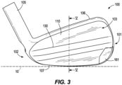
- the inflection seam 130 can stretch from the toe side 101 to the heel side 102 of the golf club head.
- the inflection seam 130 bounds the upper portion 108 to the top rail 106.
- the inflection seam 130 bounds the lower portion 109 to the sole 107.
- the inflection seam 130 marks the end of a uniform upper portion depth 116, as described below.
- the inflection seam 130 is depicted as an inflection point in any cross-sectional view taken in a top rail-to-sole direction from the toe-side view.
- the rear contour can vary between embodiments in order to allow the upper portion 108 and the lower portion 109 to have different depths, volumes, or masses.
- the lower wall 132 of the rear 103 can comprise a shelf 139 just below the inflection seam 130.
- the shelf 139 can be between the upper wall 131 and the remainder of the lower wall 132.
- the shelf 139 extends backwards and/or downwards from the inflection seam 130.
- the shelf 139 is approximately perpendicular to the loft plane 20.
- the golf club head 100 comprises the upper portion 108 and the lower portion 109, which are divided by the inflection seam 130.
- the upper portion 108 comprises a height 188 measured along the centerplane 45 from the top rail 106 to the inflection seam 130, in a direction parallel to the loft plane 20.
- the upper portion height 188 can be between 15.24 mm and 22.86 mm (0.60 inch and 0.90 inch).
- the upper portion height 188 can be between 15.24 mm and 16.51 mm (0.60 inch and 0.65 inch), 16.51 mm and 17.78 mm (0.65 inch and 0.70 inch), 17,78 mm and 19.05 mm (0.70 inch and 0.75 inch), 19.05 mm and 20.32 mm (0.75 inch and 0.80 inch), 20.32 mm and 21.59 mm (0.80 inch and 0.85 inch), 21.59 mm and 22.86 mm (0.85 inch and 0.90 inch), 15.24 mm and 17.78 mm (0.60 inch and 0.70 inch), 17.78 mm and 20.32 mm (0.70 inch and 0.80 inch), or 20.32 mm and 22.86 mm (0.80 inch and 0.90 inch).
- the lower portion 109 comprises a height 189 measured along the centerplane 45 from the top rail 106 to the inflection seam 130, in a direction parallel to the loft plane 20.
- the lower portion height 189 can be between 20.32 mm and 27.94 mm (0.80 inch and 1.10 inch).
- the lower portion height 189 can be between 20.32 mm and 21.59 mm (0.80 inch and 0.85 inch), 21.59 mm and 22.86 mm (0.85 inch and 0.90 inch), 22.86 mm and 24.13 mm (0.90 inch and 0.95 inch), 24.13 mm and 25.40 mm (0.95 inch and 1.0 inch), 25.40 mm and 26.67 mm (1.0 inch and 1.05 inch), 26.67 mm and 27.94 mm (1.05 inch and 1.10 inch), 22.86 mm and 25.40 mm (0.9 inch and 1.0 inch), or 25.40 mm and 27.94 mm (1.0 inch and 1.1 inch).
- a ratio of the upper portion height 188 and the lower portion height 189 can be between 9:8 (54:48) and 6:11 (54:99). In some embodiments, the ratio of the upper portion height 188 and the lower portion height 189 can be between 9:8 (54:48) and 6:8 (54:72), 6:8 (54:72) and 9:11 (54:66), or 9:11 (54:66) and 6:11 (54:99).
- a higher ratio of the upper and lower portion heights 188, 189 can result in a lower CG because the lower portion 109 comprises a greater depth and mass, as described below.
- a low CG improves launch and spin characteristics by reducing the torque imparted to the golf club head 100 upon impact with a golf ball.
- a low CG can also increase the ball speed and improve the feel of the golf club head 100.
- the upper portion 108 of the golf club head 100 can comprise a uniform depth.
- the upper portion depth 116 of club head 100 can be between 5.080 mm and 6.350 mm (0.200 inch and 0.250 inch).
- the upper portion depth 116 can be between 5.080 mm and 5.334 mm (0.200 inch and 0.210 inch), 5.207 mm and 5.461 mm (0.205 inch and 0.215 inch), 5.334 mm and 5.588 mm (0.210 inch and 0.220 inch), 5.461 mm and 5.715 mm (0.215 inch and 0.225 inch), 5.588 mm and 5.842 mm (0.220 inch and 0.230 inch), 5.715 mm and 5.969 mm (0.225 inch and 0.235 inch), 5.842 mm and 6.096 mm (0.230 inch and 0.240 inch), 5.969 mm and 6.223 mm (0.235 inch and 0.245 inch), 6.096 mm and 6.350 mm (0.240 inch and 0.250 inch).
- the lower portion 109 comprises a depth 118 measured perpendicular to the loft plane 20 from the strikeface 111 to an outer surface of the rear 103, along the centerplane 45.
- the lower portion depth 118 can vary in a top rail-to-sole direction and/or in a heel-to-toe direction.
- the lower portion depth 118 is equal or greater in depth than the depth of the upper portion 116 of the golf club head 100.
- the lower portion depth 118 can be between 6.86 mm and 19.81 mm (0.270 inch and 0.780 inch).
- the lower portion depth 118 can be between 6.86 mm and 8.13 mm (0.270 inch and 0.320 inch), 8.13 mm and 9.65 mm (0.320 inch and 0.380 inch), 9.65 mm and 10.92 mm (0.380 inch and 0.430 inch), 10.92 mm and 12.19 mm (0.430 inch and 0.480 inch), 12.19 mm and 13.46 mm (0.480 inch and 0.530 inch), 13.46 mm and 14.73 mm (0.530 inch and 0.580 inch), 14.73 mm and 16.00 mm (0.580 inch and 0.630 inch), 16.00 mm and 17.27 mm (0.630 inch and 0.680 inch), 17.27 mm and 18.54 mm (0.680 inch and 0.730 inch), 18.54 mm and 19.81 mm (0.730 inch and 0.780 inch), 6.86 mm and 11.94 mm (0.270 inch and 0.470 inch), 8.13 mm and 13.21 mm (0.320 inch and 0.520 inch), 9.40 mm and 14.48 mm (0.370 inch and 0.570 inch), 10.67
- the lower portion depth 118 can differ from the lower portion depth 118 at the centerplane 45.
- a minimum lower portion depth 118 in the toe 101 can be between 7.62 mm and 11.68 mm (0.300 inch and 0.460 inch).
- the lower portion depth 118 in the toe region 101 can be between 7.62 mm and 8.13 mm (0.300 inch and 0.320 inch), 8.13 mm and 8.38 mm (0.320 inch and 0.330 inch), 8.38 mm and 8.64 mm (0.330 inch and 0.340 inch), 8.64 mm and 9.14 mm (0.340 inch and 0.360 inch), 9.14 mm and 9.65 mm (0.360 inch and 0.380 inch), 9.65 mm and 10.16 mm (0.380 inch and 0.400 inch), 10.16 mm and 10.67 mm (0.400 inch and 0.420 inch), 10.67 mm and 11.18 mm (0.420 inch and 0.440 inch), or 11.18 mm and 11.68 mm (0.440 inch and 0.460 inch).
- the lower portion depth 118 at the heel 102 can differ from the lower portion depth at the centerplane 45 as well.
- a minimum lower portion depth 118 in the heel region 102 can be between 6.86 mm and 8.00 mm (0.270 inch and 0.315 inch).
- the lower portion depth 118 in the heel region 102 can be between 6.86 mm and 7.11 mm (0.270 inch and 0.280 inch), 7.11 mm and 7.37 mm (0.280 inch and 0.290 inch), 7.37 mm and 7.62 mm (0.290 inch and 0.300 inch), 7.62 mm and 7.87 mm (0.300 inch and 0.310 inch), 7.87 mm and 8.13 mm (0.310 inch and 0.320 inch), 8.13 mm and 8.64 mm (0.320 inch and 0.340 inch), 8.64 mm and 9.14 mm (0.340 inch and 0.360 inch), 9.14 mm and 9.65 mm (0.360 inch and 0.380 inch), 9.65 mm and 10.16 mm (0.380 inch and 0.400 inch), 10.16 mm and 10.67 mm (0.
- a maximum depth of the club head 100 is located within the lower portion 109 of the body 110.
- the maximum of depth of the club head 100 is measured perpendicular to the loft plane 20 from the strikeface 111 to an outer surface of the rear 103.
- the maximum depth can be between 17.02 mm to 19.56 mm (0.670 inch to 0.770 inch). In other embodiments, the maximum depth can be between 17.02 mm to 17.53 mm (0.670 inch to 0.690 inch), 17.53 mm and 18.03 mm (0.690 inch and 0.710 inch), 18.03 mm and 18.54 mm (0.710 inch and 0.730 inch), 18.54 mm and 19.05 mm (0.730 inch and 0.750 inch), or 19.05 mm and 19.56 mm (0.750 inch and 0.770 inch).
- a ratio between the upper portion depth 116 and the lower portion depth 118 can be between 1:3 and 4:5. In some embodiments, the ratio between the upper 116 and lower 118 depths can be between 1:3 and 1:2, between 1:2 and 2:3, or between 2:3 and 4:5.
- the upper and lower portions 108, 109 of the golf club head 100 can comprise a volume.
- the volume is measured from a plane adjacent the heel 102 and coincident with an edge/periphery of the faceplate 155 to the toe 101.
- the volume of the upper portion 108 can be between 3.28 cc and 9.83 cc (0.20 cubic inches and 0.60 cubic inches).
- the volume of the upper portion 108 can be between 3.28 cc and 4.92 cc (0.20 cubic inches and 0.30 cubic inches), 4.10 cc and 5.74 cc (0.25 cubic inches and 0.35 cubic inches), 4.92 cc and 6.55 cc (0.30 cubic inches and 0.40 cubic inches), 5.74 cc and 7.37 cc (0.35 cubic inches and 0.45 cubic inches), 6.55 cc and 8.19 cc (0.40 cubic inches and 0.50 cubic inches), 7.37 cc and 9.01 cc (0.45 cubic inches and 0.55 cubic inches), or 8.19 cc and 9.83 cc (0.50 cubic inches and 0.60 cubic inches). In some embodiments, the volume of the upper portion 108 is 7.87 cc (0.48 cubic inches).
- the upper portion 108 and the lower portion 109 together form the body 110, which defines the cavity 120.
- a portion of the cavity 120 within the upper portion 108 of the body 110 can have a volume between 0.05 cubic inches and 0.40 cubic inches (0.82 cc and 6.55 cc).
- the cavity volume in the upper portion 108 can be between 0.82 cc and 2.46 cc (0.05 cubic inches and 0.15 cubic inches), 1.64 cc and 3.28 cc (0.10 cubic inches and 0.20 cubic inches), 2.46 cc and 4.10 cc (0.15 cubic inches and 0.25 cubic inches), 3.28 cc and 4.92 cc (0.20 cubic inches and 0.30 cubic inches), 4.10 cc and 5.74 cc (0.25 cubic inches and 0.35 cubic inches), 4.92 cc and 6.55 cc (0.30 cubic inches and 0.40 cubic inches), or 5.74 cc and 7.37 cc (0.35 cubic inches and 0.45 cubic inches).
- the cavity volume in the upper portion 108 is 2.79 cc (0.17 cubic inches).
- the golf club head 100 below the inflection seam 130 i.e. the lower portion 109
- the volume of the lower portion 109 of the club head 100 is measured the same as the upper portion 108 ( i.e., measured from a plane adjacent the heel 102 and coincident with an edge/periphery of the faceplate 155 to the toe)
- the volume of the lower portion 109 can be between 18.85 cc and 25.40 cc (1.15 cubic inches and 1.55 cubic inches).
- the volume of the lower portion 109 can be between 18.85 cc and 22.12 cc (1.15 cubic inches and 1.35 cubic inches), 20.48 cc and 23.76 cc (1.25 cubic inches and 1.45 cubic inches), 22.12 cc and 25.40 cc (1.35 cubic inches and 1.55 cubic inches), 19.66 cc and 21.30 cc (1.20 cubic inches and 1.30 cubic inches), 21.30 cc and 22.94 cc (1.30 cubic inches and 1.40 cubic inches), or 22.94 cc and 24.58 cc (1.40 cubic inches and 1.50 cubic inches).
- the volume of the upper portion is 22.29 cc (1.36 cubic inches).
- a portion of the cavity 120 within the lower portion 109 can have a volume between 0.15 cubic inches and 0.60 cubic inches (2.46 cc and 9.83 cc).
- the cavity volume in the lower portion 109 can be between 2.46 cc and 4.10 cc (0.15 cubic inches and 0.25 cubic inches), 3.28 cc and 4.92 cc (0.20 cubic inches and 0.30 cubic inches), 4.10 cc and 5.74 cc (0.25 cubic inches and 0.35 cubic inches), 4.92 cc and 6.55 cc (0.30 cubic inches and 0.40 cubic inches), 5.74 cc and 7.37 cc (0.35 cubic inches and 0.45 cubic inches), 6.55 cc and 8.19 cc (0.40 cubic inches and 0.50 cubic inches), 7.37 cc and 9.01 cc (0.45 cubic inches and 0.55 cubic inches), or 8.19 cc and 9.83 cc (0.50 cubic inches and 0.60 cubic inches).
- the cavity volume in the lower portion 109 is 6.06 cc (0.15 cubic inches and
- the golf club head 100 can comprise the body 110 comprising a cavity 120 in a central portion of the golf club head 100.
- the cavity 120 is filled with the low-density insert 140, which increases the forgiveness of the golf club head 100 without sacrificing the solid feel and look of a tour iron.
- the forgiveness of the golf club head 100 corresponds to the amount of perimeter weighting, which is affected by the volume of the cavity 120.
- a larger cavity eliminates more mass from a central region of the golf club head 100 than a smaller cavity. Consequently, a larger cavity allows more weight to be positioned on the perimeter of the golf club head 100.
- the cavity 120 can have a volume between 0.2 cubic inches and 0.8 cubic inches (3.28 cc and 13.11 cc).
- the cavity 120 volume can be between 3.28 cc and 4.92 cc (0.2 cubic inches and 0.3 cubic inches), 3.28 cc and 4.10 cc (0.2 cubic inches and 0.25 cubic inches), 4.10 cc and 4.92 cc (0.25 cubic inches and 0.30 cubic inches), 4.92 cc and 6.55 cc (0.30 cubic inches and 0.40 cubic inches), 4.92 cc and 5.74 cc (0.30 cubic inches and 0.35 cubic inches), 5.74 cc and 6.55 cc (0.35 cubic inches and 0.40 cubic inches), 6.55 cc and 8.19 cc (0.40 cubic inches and 0.50 cubic inches), 6.55 cc and 7.37 cc (0.40 cubic inches and 0.45 cubic inches), 7.37 cc and 8.19 cc (0.45 cubic inches and 0.50 cubic inches), 8.19 cc and 9.83 cc (0.50 cubic inches), 6.
- the cavity 120 can have a volume of 3.28 cc (0.20 cubic inch), 3.61 cc (0.22 cubic inch), 3.93 cc (0.24 cubic inch), 4.26 cc (0.26 cubic inch), 4.59 cc (0.28 cubic inch), 4.92 cc (0.30 cubic inch), 5.24 cc (0.32 cubic inch), 5.57 cc (0.34 cubic inch), 5.90 cc (0.36 cubic inch), 6.23 cc (0.38 cubic inch), 6.55 cc (0.40 cubic inch), 6.88 cc (0.42 cubic inch), 7.21 cc (0.44 cubic inch), 7.54 cc (0.46 cubic inch), 7.87 cc (0.48 cubic inch), 8.19 cc (0.50 cubic inch), 8.52 cc (0.52 cubic inch), 8.85 cc (0.54 cubic inch), 9.18 cc (0.56 cubic inch), 9.50 cc (0.58 cubic inch), 9.83 cc (0.60 cubic inch), 10.16 cc (0.62 cubic inch), 10.16
- the cavity 120 can have a volume that is between 5% and 60% of the total club head volume, described above. In some embodiments, the cavity 120 can have a volume that is between 5% and 10%, 10% and 30%, 15% and 35%, 20% and 40%, 25% and 45%, 30% and 50%, 35% and 55%, or 40% and 60% of the total club head volume. In one embodiment, the volume of the cavity 120 is between 17% and 32% of the club head volume.
- the golf club head 100 comprises a lower CG than a golf club head having a flat rear, as exemplified in Example 3 below.
- the golf club head 100 can comprise a CG 60 that is lower than the CG of a flat back comparison golf club head by between 0.762 mm and 1.270 mm (0.030 inch and 0.050 inch).
- the lower CG 60 causes the golf club head 100 to have better launch characteristics, better spin characteristics, and higher ball speed than a flat back golf club head.
- the thickness of the rear 103 of the body 110 also affects the weighting and thereby the CG location of the golf club head 100.
- the thickness is measured from an exterior surface of the rear 103 to an interior surface of the rear 103 within the cavity 120.
- the rear 103 of the body 110 is thicker adjacent the sole 107 of the body 110. Due to the density of the body 110 material, the greater thickness adjacent the sole 107 moves mass downward compared to a golf club head body having a uniform rear thickness.
- the rear 103 of the body 110 can have a thickness 113.
- the rear thickness 113 can range between 0.762 mm and 2.540 mm (0.030 inch and 0.100 inch).
- the thickness 113 can be 0.762 mm (0.030 inch), 1.016 mm (0.040 inch), 1.270 mm (0.050 inch), 1.524 mm (0.060 inch), 1.778 mm (0.070 inch), 2.032 mm (0.080 inch), 2.286 mm (0.090 inch), or 2.540 mm (0.100 inch).
- the rear thickness 113 can be constant across the rear 103. In some embodiments, the rear thickness 113 varies across the rear 103 in a heel-to-toe direction and/or in a top rail-to-sole direction. Varying the thickness 113 of the rear 103 can assist in moving mass towards the sole 107 and rear 103 of the golf club head 100. Shifting the mass towards the sole 107 and rear 103 lowers the CG, which improves launch characteristics, improves spin characteristics, and increases ball speed.
- body 110 can comprise an internal peripheral edge 127 that defines the cavity 120 outer boundaries.
- the internal peripheral edge 127 circumscribes the cavity 120.
- the peripheral edge 127 internally bounds the top rail 106, sole 107, toe 101, and heel 102.
- the internal peripheral edge 127 can follow the contours of the external edge of the golf club head 100. Because the peripheral edge 127 of the cavity 120 extends as close to the edges of the golf club head 100 as possible, the size of the cavity 120 is maximized. Consequently, the size of the low-density insert 140 and its weighting benefits are also maximized.
- the peripheral edge 127 gently tapers so that in a cross-section of the golf club head 100, taken in a front-to-rear direction, the cavity 120 covers a larger area closer to the front 104 and smaller area closer to the rear 103.
- this tapered geometry enables the larger area adjacent the front 104 to harbor more surface area of the low-density insert thereby placing it closer to the front 104.
- Less internal cavity area is left for the low density insert and more of the high density material is left in the rear 103 of the golf club head 100.
- the shaping of the cavity 120 can enable the placement of more mass adjacent the rear 103 and sole 107 of the golf club head 100, shifting the CG down and back.
- the front 104 of the body 110 further comprises an indentation 142 for receiving the faceplate 155.
- the indentation 142 connects to a front opening of the cavity 120, but is not considered part of the cavity 120.
- the indentation 142 comprises a peripheral edge 143 that generally follows the contours of the golf club head 100, including, but not limited to, the top rail 106, an edge of the body within the toe 101, the sole 107, and a roughly vertical dividing line adjacent the heel 102.
- the peripheral edge 143 of the indentation 142 is offset from the internal peripheral edge 127 that defines the cavity 120.
- the footprint of the indentation 142 is larger than the area circumscribed by the internal peripheral edge 127 at a front of the cavity 120.
- the indentation 142 has a depth approximately equivalent to the thickness of the faceplate 155, described below.
- the faceplate 155 aligns with the indentation 142 and sits within the cavity 120 and is seated on the indentation 142.
- the insert 140 (as described below) fits within the cavity to a volume that is flush with the indentation 142.
- the remaining volume of the cavity 120 is filled by the faceplate 155 that seats on the indentation 142.
- the insert 140 and the faceplate 155 fill the entire volume of the cavity 120 and the indentation 142 of the golf club head 100.
- the insert 140 does not cover the indentation 142, but rather sits flush with the indentation 142. Thereby, the insert 140 does not interfere with the faceplate 155 seating on the indentation 142.
- the insert 140 does not fill the volume of the cavity 120 to the indentation 142, but only a portion. Again, these embodiments entail an insert 140 that does not interfere with the faceplate 155 seating on the indentation 142.
- the golf club head 100 comprises a low-density insert 140 that fits within the cavity 120 of the body 110.
- the insert 140 is shaped to fit within the cavity 120.
- the insert 140 completely fills or partially fills the cavity 120, as described above.
- the insert 140 shares wall geometry with the cavity 120.
- the shape of the insert 140 can be identical or almost identical to the shape of the cavity 120.
- the volume and other dimensions of the insert 120 approximately correspond to the respective volume and other dimensions of the cavity 140.
- manufacturing tolerances and the insertion of tape and/or adhesive into the cavity 120 can necessitate a slightly smaller volume for the insert 140 compared to the cavity 120.
- a multi-material insert 440 is employed in place of the insert 140.
- the multi-material insert 440 can comprise dimensions and a volume similar to the dimensions and volume of insert 140.
- the multi-material insert 440 can comprise a first portion 150 and a second portion 160 of different materials having different densities.
- the first portion 450 is a low-density portion and the second portion 460 is a weight. Adding weight to a lower portion of the insert 440 lowers the CG 60 of the golf club head 100, which improves launch characteristics and increases ball speed. Adding weight to lower the CG 60 can also increase ball speed and improve the feel of the golf club head 100.
- the first portion 450 is a vibration damping material
- the second portion 460 is a low-density material. Forming the first portion 450 from a vibration damping material can affect the feel and sound of the golf club head 100. The feel, sound, and perimeter weighting of the golf club head 100 can be altered by forming the insert 440 from multiple materials.
- the insert 440 can be formed with the first portion 450 and the second portion 460 in any orientation or combination with respect to each other, so long as the first and second portions 450, 460 form an insert 440 configured to fit within the cavity 120 of the body 110 as described above.
- the first portion 450 can be separate from the second portion 460 or integrally formed into a single multi-material insert 440.
- Various embodiments of a multi-material insert 440, 440B, 440C, and 440D are depicted in FIGS. 6-9 and described below.
- the insert 440 comprises a first portion 450 and a second portion 460.
- Insert 440 can be designed to fit within the cavity 120 of golf club head 100.
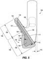
- the cross-sectional cutaway of FIG. 6 is taken along the centerplane 45 of the golf club head 100.
- the first portion 450 of the insert 440 is adjacent the strikeplate 155 and comprises a first material.
- the second portion 460 of the insert 440 is adjacent the rear 103 of the body 110 and comprises a second material.
- the first portion 450 overlaps the second portion 460.
- the first portion 450 of the insert 440 comprises a front surface that abuts a rear surface 128 of the faceplate 155.
- the second portion 460 does not engage the faceplate 155.
- the second portion 460 comprises a front surface that engages a rear surface of the first portion 450.
- the second portion 460 is confined within a section of the cavity 120 within the lower portion 109 of the golf club head 100.
- the engaging surfaces of one or both of the first and second portions 450, 460 comprise small features (not shown) that extend out from the generally planar surfaces to increase the engagement surface area. These small features can comprise protrusions, lips, ribs, hooks, or any other suitable feature. These features allow the first portion 450 to be secured onto the second portion 460 through a molding process or co-molding process.
- the second embodiment of a multi-material insert 440B comprises a first portion 450B and a second portion 460B, arranged as illustrated in FIG. 7 .
- the first portion 450B forms an upper section of the insert 440B and the second portion 460B forms a lower section of the insert 440B.
- Both the first portion 450B and the second portion 460B are flush against the faceplate 155.
- the first portion 450B fills the section of the cavity 120 within the upper portion 108 of the body 110.
- the second portion 460B fills the section of the cavity 120 within the lower portion 109 of the body 110.
- the second portion 460B is flush against the entire interior sole wall of the cavity 120.
- the third embodiment of a multi-material insert 440C comprises a first portion 450C and a second portion 460C, arranged as illustrated in FIG. 8 .
- the first portion 450C comprises a majority of the volume of the insert 440C.
- the first portion 450C extends partially into a rear end of the insert 440C.
- the entire second portion 460C is located rearward of the first portion 450C.
- the first portion 450C is flush against the faceplate 155 from the top rail 106 to the sole 107 in the cavity of the golf club head 100.
- the second portion 460C does not engage the faceplate 155.
- the second portion 460C partially fills and is completely located in the section of the cavity 120 within the lower portion 109 of the body 110.
- the second portion 460C engages a section of an interior sole wall and rear backwall of the cavity 120.
- the second portion 460C is formed from a high density material.
- the fourth embodiment of a multi-material insert 440D comprises a first portion 450D and a second portion 460D, arranged as illustrated in FIG. 9 .
- the first portion 450D extends partially into a rear end of the insert 440D.
- the first portion 450D engages the second portion 460D along a plane that is angled with respect to the loft plane 20.
- the first portion 450D is wider adjacent a bottom of the insert 440D than adjacent a top of the insert 440D.
- the first portion 450D is wider adjacent the sole 107 than adjacent the top rail 106.
- the second portion can be located primarily in the toe 101 of the golf club head 110.
- This provides a toe weighting effect, acting similar to the toe weight 161, described below.
- Embodiments with the second portion of the insert acting as a toe weight have no need for an external toe weight. This can improve the aesthetics and simplify manufacturing by eliminating the need for welding in a toe weight.
- the insert 140 can fully or partially fill the cavity 120 of the golf club head 100.
- the insert 140 can fill a volume of the cavity 120 between 80% and 100%.
- the insert 140 can fill a volume of the cavity 120 between 80% and 85%, 85% and 90%, 90% and 95%, 95% and 100%, 80% and 90%, or 90% and 100%.
- the first portion 450 can fill a majority of the cavity 120.
- the second portion 460 can fill the remainder of the cavity 120.
- the first and second portions together only partially fill the cavity 120.
- the first portion 450 can fill between 20% to 90% of the volume of the cavity 120.
- the first portion 450 can fill between 20% and 30%, 30% and 40%, 40% and 50%, 50% and 60%, 60% and 70%, 70% and 80%, or 80% and 90%.
- the second portion 460 can fill between 10% to 80% of the volume of the cavity 120. In some embodiments, the second portion 460 can fill between 10% and 20%, 20% and 30%, 30% and 40%, 40% and 50%.
- the volumes of the first and second portions 450, 460 affect the overall weighting of the golf club head 100 because the first and second portions 450, 460 are formed with different materials having different densities, as described in detail below. In the design of a golf club head, many design parameters must be considered together. By forming the insert from multiple materials, the mass placement can be controlled to increase perimeter weighting and lower the CG, leading to improved launch characteristics and higher ball speeds.
- a tape layer 150 is placed within the cavity 120 between the insert 140 and the strikeface 111. As seen in FIG. 12 , the tape layer 150 is sandwiched between the insert 140 and the faceplate 155.
- Golf club head embodiments having a multi-material insert, such as 440 can similarly comprise a tape layer 150 between the first portion 450 and the faceplate 155 or between the first portion 450 of the insert 440 and the body 110.
- the insert 140 fits within the body 110
- the tape layer 150 can optionally lay on the insert 140
- the faceplate 155 covers the tape layer 150 and fills the indentation 142 of the body 110.
- a second tape layer can lie flush with an interior surface of the rear 103 of the body 110 within the cavity 120.
- the second tape layer can be sandwiched between the rear 103 of the body 110 and the insert 140.
- a third tape layer can lie flush at a bottom of the cavity 120.
- the third tape layer can be sandwiched between the sole 107 of the body 110 and the insert 140.
- the golf club head 100 can comprise one or more of the first tape layer 150, the second tape layer, and the third tape layer.
- the tape layer 150, second tape layer, or third tape layer can comprise a material such as a very high bond (hereafter "VHB") tape.
- VHB very high bond
- the VHB tape is compressible, such that an original thickness of the tape layer 150 (measured orthogonal to the strikeface 111) when initially provided is greater than a thickness of the compressed tape layer within the assembled golf club head 100.
- the second and third tape layers can be similarly compressible.
- the compressible nature of the one or more tape layers reduces the likelihood of rattling caused by manufacturing tolerances between the body 110 and the insert 140.
- the one or more tape layers can provide vibration damping as well as positively affect the feel and sound of the golf club head 100.
- the full golf club head 100 is formed by the combination of the body 110, the insert 120, and the faceplate 155.
- the body 110 comprises an opening of the cavity 120 at the front 104 of the golf club head 100.
- the opening is covered by the faceplate 155, to entirely enclose the cavity 120 and the insert 140.
- the cavity 120 and the insert 140 are not visible from the outside of the golf club head 100 when the insert 140 is positioned within the cavity 120. By concealing the insert 140 within the golf club head 100, the look of the golf club head 100 can resemble the look of traditional tour irons.
- the strikeface 111 can cover between 70% and 95% of the surface area of the front 104 of the golf club head 100. In some embodiments, the strikeface 111 can cover between 70% and 80%, 75% and 85%, 80% and 90%, or 85% and 95% of the surface area of the front of the golf club head 100. Furthermore, a front surface of the strikeface 111 may comprise one or more grooves. In some embodiments, the grooves extend beyond the edge of the faceplate 155 and onto a portion of the body 110.
- the faceplate 155 can comprise a different material than the body 110, as described below. In some embodiments, the material of the faceplate 155 is stronger than the material of the body 110. To exploit the benefits of the faceplate 155 material, the majority of the strikeface 111 is formed by the faceplate 155. The faceplate 155 can form between 50% and 95% of the surface area of the front 104 of the golf club head 100. In some embodiments, the faceplate 155 can form between 50% and 60%, 60% and 70%, 70% and 80%, 80% and 90%, or 85% and 95% of the surface area of the strikeface 111. Despite having different materials, the faceplate 155 and the body 110 portion of the strikeface 111 both give a solid feel because the insert 140 solidly supports the faceplate 155. The body 110, the insert 140, and the faceplate 155 can all contribute to a consistent feel and sound for the golf club head 100 when the golf club head 100 impacts a golf ball on various regions of the faceplate 155.
- the support provided to the faceplate 155 by the insert 140 enables a thin faceplate 155 to be used in the golf club head 100.
- the faceplate 155 of the golf club head 100 has a thickness 112.
- the thickness 112 can range between 0.762 mm and 2.540 mm (0.030 inch and 0.100 inch).
- the faceplate thickness 112 can be 0.762 mm (0.030 inch), 1.016 mm (0.040 inch), 1.270 mm (0.050 inch), 1.524 mm (0.060 inch), 1.778 mm (0.070 inch), 2.032 mm (0.080 inch), 2.286 mm (0.090 inch), or 2.540 mm (0.100 inch).
- the faceplate thickness 112 can be constant across the faceplate 155.
- the faceplate thickness 112 can vary in a heel-to-toe direction or in a top rail-to-sole direction. In some embodiments, the faceplate thickness 112 can vary in a radial direction from a center of the faceplate 155.
- the faceplate 155 can further comprise variable thickness regions.
- a central region of the faceplate 155 can be thicker than a peripheral region of the faceplate 155.
- the thickened central region can comprise an elliptical shape. The thickness of the faceplate 155 can taper from the central towards a periphery of the faceplate 155.
- the golf club head 100 can further comprise other perimeter types of weights.
- the golf club head 100 can further comprise a tip weight 160.
- the tip weight 160 is a weight that fits at the juncture between the hosel 105 and the golf club shaft.
- the tip weight 160 provides additional perimeter weighting to the club head 100.
- the tip weight 160 fits within the hosel 105 of the body 110.
- the tip weight 160 can by cylindrical, spherical, cube-shaped, or any other suitable shape.
- the tip weight 160 may be located higher or lower in the hosel 105 than is pictured in FIG. 13 .
- the body 110 of the golf club head 100 can further comprise a toe cavity 114.
- the toe cavity 114 is designed to house a toe weight 161, which improves the perimeter weighting and swing characteristics of the golf club head 100.
- FIG. 3 illustrates the toe cavity 114 with the toe weight 161 installed.
- FIG. 13 illustrates the toe weight 161 removed from the toe cavity 114.
- the toe cavity 114 is located partially in the sole 107 and partially in the toe 101.
- the toe cavity 114 is located fully in the toe 101 of the golf club head 100, adjacent the sole 107.
- the toe cavity 114 is located completely in the sole 107, adjacent the toe 101.
- the toe cavity 114 is located completely in the toe 101.
- the toe cavity 114 is located in the center of the toe 101, approximately half way between the top rail 106 and the sole 107.
- the toe cavity 114 is visible from the rear view of the body 110 of the club head 100. In other embodiments, the toe cavity 114 is not visible from the rear view of the body 110. In some embodiments, the toe cavity 114 is visible from the toe-side view of the body 110. In other embodiments, the toe cavity 114 is not visible from the toe-side view of the body 110. In some embodiments, the toe cavity 114 is visible from the sole view of the body 110. In other embodiments, the toe cavity 114 is not visible from the sole view of the body 110. In the embodiment of FIGS. 1-13 , the toe cavity 114 is visible from the rear view, the sole view, and the toe-side view.
- the toe weight 161 is shaped to match the contours of the toe cavity 114 of the body 110.
- An external wall of the toe weight 161 is designed follow the curve of the golf club head body 110.
- the mass of the toe weight 161 can be between 5% and 45% of the mass of the body 110.
- the mass of the toe weight 161 can be between 5% and 20%, 5% and 15%, 10% and 20%, 15% and 25%, 20% and 40%, 20% and 30%, 30% and 40%, or 35% and 45% of the mass of the body 110.
- the body 110 of the golf club head 100 can further comprise a toe screw weight port, not depicted, in the toe 101.
- the golf club head 100 can further comprise a toe screw weight that fits within the screw weight port.
- the toe screw weight can comprise a weight between 2 grams and 15 grams, as described below. A screw weight having one weight value can be exchanged for a different screw weight having a different weight value in order to customize the golf club head 100 to a golfer's swing.
- weights as described above including the insert, toe weight, tip weight, and the toe screw weight.
- Other embodiments can comprise a multi-material insert combined with one or more of a toe weight, a tip weight, and a toe screw weight.
- the materials that form the body 110, the insert 140, and the faceplate 155 affect the mass distribution of the golf club head 100. Consequently, the MOI and CG of the golf club head 100 are also affected by the densities of the materials. Furthermore, the materials provide the strength and flexibility necessary for the golf club head 100.
- the golf club head 100 comprises one or more, two or more, three or more, or four or more materials. In some embodiments, the materials may be a first density, second density, third density, fourth density, fifth density or sixth density.
- the faceplate 155 can comprise a first material of a first density.
- the body 110 can comprise a second material of a second density.
- the insert 140 can comprise a third material of a third density.
- the third density can be less than the first density and/or the second density.
- the faceplate 155 can be the same material as the body 110 (and thereby the same densities).
- the insert 440 can comprise two or more materials wherein the materials are a different density over each other, and can be different or the same over the materials of the faceplate 155 and/or the body 110.
- the body 110 may comprise a material, such as steel, a steel alloy, or any other suitable material.
- the body 110 can comprise a material of a density that is different over the faceplate 155 and the insert 140.
- the material can comprise a material selected from the group consisting of a steel-based material or a steel alloy.
- the body material can be 8620 carbon steel, which comprises iron and approximately 0.17-0.23 % wt. carbon, 0.15-0.35 % wt. silicon, 0.60-0.90 % wt. manganese, 0.15-0.30 % wt. molybdenum, 0.40-0.70 % wt. nickel, 0.40-0.65 % wt.
- the body material can be 300 grade steel, which comprises iron and approximately 18-19 % wt. nickel, 8.5-9.5 % wt. cobalt, 4.6-5.2 % wt. molybdenum, 0.5-0.8 % wt. titanium, 0.05-0.15 % wt. aluminum, and trace amounts of other elements.
- the body material can be maraging steel, which comprises iron and approximately 17-19 % wt. nickel, 8-12.5 % wt. cobalt, 3.0-5.2 % wt. molybdenum, 0.15-1.6 % wt.
- the density of the body 110 material can range between 7.70 and 8.10 grams per cubic centimeter (hereafter "g/cc"). In some embodiments, the density of the body material can be 7.70 g/cc, 7.75 g/cc, 7.80 g/cc, 7.85 g/cc, 7.90 g/cc, 7.95 g/cc, 8.05 g/cc, or 8.10 g/cc. In one embodiment, the density of the body material is 7.85 g/cc.
- the insert 140 comprises a material, such as titanium, a titanium alloy, aluminum, an aluminum alloy, an elastomer, a polymer matrix composite, any other suitable low density material, or any other suitable density material that is lower than the body 110 material.
- the aluminum alloy can be high strength aluminum alloy, or a composite aluminum alloy coated with a high-strength alloy.
- the polymer matrix composite can be a glass-filled elastomer, a stainless steel-filled elastomer, a tungsten-filled elastomer, a thermoplastic polyurethane (TPU), a thermoplastic elastomer (TPE), or any other elastomer matrix composite, a Kevlar ® (aramid) fiber-reinforced polymer, a carbon-fiber reinforced polymer, or any combination of a suitable resin and a suitable reinforcing fiber.
- the polymer matrix composite material can be an elastomer matrix composite.
- the metal material can be a steel-based material, a titanium-based material, an aluminum alloy, a titanium alloy, or any combination thereof.
- the steel-based material can be a 17-4 PH stainless steel, 431, 455, 475, C300, a maraging steel, or other types of stainless steel.
- the aluminum alloy can be high strength aluminum alloy, or a composite aluminum alloy coated with a high-strength alloy.
- the titanium alloy can be Ti-9S, Ti-6-4, and Ti-15-3-3-3.
- the titanium alloy can be an ⁇ - ⁇ titanium alloy.
- the insert 140 may comprise a material of a density that is different over the body 110 and the faceplate 155. Suitable materials for the insert 140 can include any materials that have a density lower than the density of the body material. In some embodiments, particularly ones with a metal insert material, the density of the insert 140 material can range between 2.4 to 5.0 g/cc.
- the density of the insert 140 material can be 2.4 g/cc, 2.5 g/cc, 2.6 g/cc, 2.7 g/cc, 2.8 g/cc, 2.9 g/cc, 3.0 g/cc, 3.1 g/cc, 3.2 g/cc, 3.3 g/cc, 3.4 g/cc, 3.5 g/cc, 3.6 g/cc, 3.7 g/cc, 3.8 g/cc, 3.9 g/cc, 4.0 g/cc, 4.1 g/cc, 4.2 g/cc, 4.3 g/cc, 4.4 g/cc, 4.5 g/cc, 4.6 g/cc, 4.7 g/cc, 4.8 g/cc, 4.9 g/cc, or 5.0 g/cc.
- the insert 140 material is aluminum and the density of the insert 130 material is approximately 2.7 g/cc,
- the density of the insert 140 can range between 1.0 and 12.0 g/cc. In polymer matrix composite material preferred embodiments, the density of the insert 140 can range between 1.0 g/cc and 5.0 g/cc. In some embodiments, the density of the insert 140 can be 1.0 g/cc, 1.5 g/cc, 2.0 g/cc, 2.5 g/cc, 3.0 g/cc, 3.5 g/cc, 4.0 g/cc, 4.5 g/cc, or 5.0 g/cc. When the density of the insert 140 is low, a central portion of the club head that houses the insert 140 is lighter, allowing weight to be redistributed to the periphery of the club head. The redistributed weight increases the MOI.
- the insert 440 comprises distinct portions formed from different materials and different densities.
- the first and second portions 450, 460 of the insert 440 can each be formed from any of the materials mentioned above for the single-material insert.
- the first portion 450 of the insert 140 is formed from an elastomer or polymer matrix composite material, comprising a density between 0.8 g/cc and 1.4 g/cc
- the second portion 460 of the insert 440 is formed from aluminum or an aluminum alloy, comprising a density between 1.5 g/cc and 3.0 g/cc.
- the first portion 450 of the insert 440 can comprise any of the material mentioned above having a density between 1.0 g/cc and 12.0 g/cc.
- the second portion 460 of the insert 440 can comprise a material that has a density higher than the density of the body material.
- the second portion 460 of the insert 440 can be a weight portion comprising any of the materials described below for the toe weight 161 and having a density between 14.0 and 19.6 g/cc. In some of these embodiments, the toe weight 161 is not necessary, because the second portion 460 of the insert 140 serves a similar purpose.
- the weight of the insert 140 or 440 can range between 10 grams and 50 grams.
- the weight of the insert 140 can be 10 grams, 11 grams, 12 grams, 13 grams, 14 grams, 15 grams, 16 grams, 17 grams, 18 grams, 19 grams, 20 grams, 21 grams, 22 grams, 23 grams, 24 grams, 25 grams, 26 grams, 27 grams, 28 grams, 29 grams, 30 grams, 31 grams, 32 grams, 33 grams, 34 grams, 35 grams, 36 grams, 37 grams, 38 grams, 39 grams, 40 grams, 41 grams, 42 grams, 43 grams, 44 grams, 45 grams, 46 grams, 47 grams, 48 grams, 49 grams, or 50 grams.
- the insert 140 or 440 can range between 10 grams and 70 grams. In some embodiments, the weight of the multi-material insert 140 or 440 can be between 10 grams and 20 grams, 20 grams and 30 grams, 30 grams and 40 grams, 40 grams and 50 grams, 50 grams and 60 grams, or 60 grams and 70 grams.
- the insert 140 and 440 provides structural support to the strikeface 111.
- the insert 140 or 440 or a portion of the insert 140 or 440 can comprise a Rockwell B hardness between 30 HRB and 100 HRB.
- the insert 140 or 440 or a portion of the insert 140 or 440 can have Rockwell B hardness between 30 HRB and 40 HRB, 40 HRB and 50 HRB, 50 HRB and 60 HRB, 60 HRB and 70 HRB, 70 HRB and 80 HRB, 80 HRB and 90 HRB, 90 HRB and 100 HRB.
- the insert 140 or a portion of the insert 140 can have a Rockwell B hardness of 30 HRB, 31 HRB, 32 HRB, 33 HRB, 34 HRB, 35 HRB, 36 HRB, 37 HRB, 38 HRB, 39 HRB, 40 HRB, 41 HRB, 42 HRB, 43 HRB, 44 HRB, 45 HRB, 46 HRB, 47 HRB, 48 HRB, 49 HRB, 50 HRB, 51 HRB, 52 HRB, 53 HRB, 54 HRB, 55 HRB, 56 HRB, 57 HRB, 58 HRB, 59 HRB, 60 HRB, 61 HRB, 62 HRB, 63 HRB, 64 HRB, 65 HRB, 66 HRB, 67 HRB, 68 HRB, 69 HRB, 70 HRB, 71 HRB, 72 HRB, 73 HRB, 74 HRB, 75 HRB, 76 HRB, 77 HRB, 78 HRB, 79 HRB, 80 HRB, 81 HRB, 82 HRB
- the insert 140 or 440 or a portion of the insert 140 or 440 can comprise a Rockwell C hardness between 30 HRC and 60 HRC.
- the insert 140 or 440 can have a hardness between 30 HRC and 40 HRC, 35 HRC and 45 HRC, 40 HRC and 50 HRC, 45 HRC and 50 HRC, or 50 HRC and 60 HRC.
- the insert can have a Rockwell C hardness of 30 HRC, 31 HRC, 32 HRC, 33 HRC, 34 HRC, 35 HRC, 36 HRC, 37 HRC, 38 HRC, 39 HRC, 40 HRC, 41 HRC, 42 HRC, 43 HRC, 44 HRC, 45 HRC, 46 HRC, 47 HRC, 48 HRC, 49 HRC, 50 HRC, 51 HRC, 52 HRC, 53 HRC, 54 HRC, 55 HRC, 56 HRC, 57 HRC, 58 HRC, 59 HRC, or 60 HRC.
- the insert hardness is 44 HRC.
- the faceplate 155 can be formed from a faceplate material.
- the faceplate material is the same material as the body 110 material.
- the faceplate material is a different material than the body material.
- the faceplate 155 can comprise a material of a density that is different over the body 110 and the insert 140.
- the faceplate material can be a steel-based material, a titanium-based material, a titanium alloy, or any combination thereof.
- the steel-based material can be a carbon steel, a 17-4 PH stainless steel, 431, 455, 475, C300, a maraging steel, or other types of stainless steel.
- the titanium alloy can be Ti-7S+ (ST721), Ti-9S, Ti-6-4, Ti-15-3-3-3, or any other suitable titanium alloy.
- the titanium alloy may be an ⁇ - ⁇ titanium alloy.
- the density of the faceplate 155 material can range between 2.6 and 8.7 g/cc.
- the density of the faceplate material can be 2.6 g/cc, 2.8 g/cc, 3.0 g/cc, 3.2 g/cc, 3.4 g/cc, 3.6 g/cc, 3.8 g/cc, 4.0 g/cc, 4.2 g/cc, 4.4 g/cc, 4.6 g/cc, 4.8 g/cc, 5.0 g/cc, 5.2 g/cc, 5.4 g/cc, 5.6 g/cc, 5.8 g/cc, 6.0 g/cc, 6.2 g/cc, 6.4 g/cc, 6.6 g/cc, 6.8 g/cc, 7.0 g/cc, 7.2 g/cc, 7.4 g/cc, 7.6 g/cc, 7.8 g/cc, 8.0 g/cc, 8.2 g/cc, 8.4 g/cc, 8.
- the tip weight 160 can comprise a material that is different over the material of the body 110, faceplate 155, and the insert 140 or 440.
- the tip weight 160 comprises a high-density material, such as tungsten or any other suitable metal or metal alloy material.
- the density of the tip material 160 can range between 1.1 g/cc and 19.6 g/cc.
- the density of the tip weight 160 material can be 1.1 g/cc, 1.5 g/cc, 2.0 g/cc, 2.5 g/cc, 3.0 g/cc, 3.5 g/cc, 4.0 g/cc, 4.5 g/cc, 5.0 g/cc, 5.5 g/cc, 6.0 g/cc, 6.5 g/cc, 7.0 g/cc, 7.5 g/cc, 8.0 g/cc, 8.5 g/cc, 9.0 g/cc, 9.5 g/cc, 10.0 g/cc, 10.5 g/cc, 11.0 g/cc, 11.5 g/cc, 12.0 g/cc, 12.5 g/cc, 13.0 g/cc, 13.5 g/cc, 14.0 g/cc, 14.5 g/cc, 15.0 g/cc, 15.5 g/cc, 15.8
- the weight of the tip weight 160 can range between 0 grams and 18 grams. In some embodiments, the weight of the tip weight 160 can be 0 grams (in the embodiment where there is no tip weight), 1 grams, 2 grams, 3 grams, 4 grams, 5 grams, 6 grams, 7 grams, 8 grams, 9 grams, 10 grams, 11 grams, 12 grams, 13 grams, 14 grams, 15 grams, 16 grams, 17 grams, or 18 grams. In most embodiments, the tip weight 160 ranges between 0 grams and 9 grams.
- the toe weight 161 can comprise a material that is different over the material of the body 110, faceplate 155, the tip weight 160, and the insert 140 or 440.
- the toe weight 161 comprises a high-density material, such as tungsten or any other suitable metal or metal alloy material.
- the density of the toe weight 161 material can range between 14.0 and 19.6 g/cc.
- the density of the toe weight 161 material can be 14.0 g/cc, 14.2 g/cc, 14.4 g/cc, 14.6 g/cc, 14.8 g/cc, 15.0 g/cc, 15.2 g/cc, 15.4 g/cc, 15.6 g/cc, 15.8 g/cc, 16.0 g/cc, 16.2 g/cc, 16.4 g/cc, 16.6 g/cc, 16.8 g/cc, 17.0 g/cc, 17.2 g/cc, 17.4 g/cc, 17.6 g/cc, 17.8 g/cc, 18.0 g/cc, 18.2 g/cc, 18.4 g/cc, 18.6 g/cc, 18.8 g/cc, 19.0 g/cc, 19.2 g/cc, 19.4 g/cc, or 19.6 g/cc.
- the weight of the toe weight 161 can range between 10 grams and 40 grams. In some embodiments, the weight of the toe weight 161 can be 10 grams, 11 grams, 12 grams, 13 grams, 14 grams, 15 grams, 16 grams, 17 grams, 18 grams, 19 grams, 20 grams, 21 grams, 22 grams, 23 grams, 24 grams, 25 grams, 26 grams, 27 grams, 28 grams, 29 grams, 30 grams, 31 grams, 32 grams, 33 grams, 34 grams, 35 grams, 36 grams, 37 grams, 38 grams, 39 grams, and 40 grams. In some embodiments, the weight of the toe weight 161 can range between 12 grams and 26.5 grams.
- the toe screw weight can comprise any high-density material similar to the high-density materials of the tip weight or the toe weight.
- the density of the toe screw material can be similar to the density of the tip weight materials.
- the weight of the toe screw weight can be similar to the weight of the tip weight, described above.
- golf club head 600 can be a tour style golf club head with forgiveness as discussed above.
- the golf club head 100 can comprises a body 610 having a cavity 620 that houses an insert 640.
- the golf club head 600 comprises a faceplate 655, a body 610, and an insert 640.
- the body 610 comprises an upper portion 608, a lower portion 609, a sole 607, a rear 603, and a top rail 606.
- the rear 603 can further comprise an inflection seam 630.
- the inflection seam 630 is the boundary between the upper portion 608 and lower portion 609 of the golf club head 600.
- the faceplate 655 and a portion of the body define a strikeface 611 (striking surface) of the golf club head.
- the faceplate 655, the sole 607, the rear 603, and the top rail 606 enclose a cavity 620.
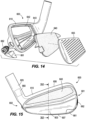
- FIGS. 14-23 depict a golf club head 600 similar to golf club head 100.
- the golf club head 600 comprises a body 610 forming a cavity 620, a faceplate 655, a rear opening 680 and a low-density insert 640 in the cavity.
- the body 610 comprises an upper portion 608, a lower portion 609, a sole 607, a rear 603, and a top rail 606.
- the rear 603 can further comprise an inflection seam 630.
- the inflection seam 630 is the boundary between the upper portion 608 and lower portion 609 of the golf club head 600.
- the faceplate 655 and a portion of the body 610 define a strikeface 611 (striking surface) of the golf club head 600.
- the body 610 is similar to body 110.
- the faceplate 655, the sole 607, and the rear 603 form a cavity 620 with a rear opening 680 in the upper portion 608 of the golf club head 600.
- the rear opening 680 of the body 610 partially exposes the cavity 620.
- the insert 640 is visible through the opening 680 in the rear 603.
- the body 610 further comprises an indentation 642 in the front 604 of the body 610 for receiving the faceplate 655 similar to the indentation 142 described above for club head 100.
- the insert 640 harbors within the cavity 620.
- the insert 640 can comprise a non-metal or polymer based material.
- the insert material can be injected into the cavity 620 of the golf club head 600 through the rear opening 680 to form the insert 640 within the cavity 620.
- the insert 640 can comprise a metal material, similar to the insert 140 described above.
- the faceplate 655 encloses the cavity 620 at a front 604 of the golf club head 600.
- the faceplate 655 and a front 604 of the body 610 together define a strikeface 611.
- the golf club head 600 is a tour iron club head, and has a volume between 1.8 cubic inches and 2.7 cubic inches (30 cubic centimeters (cc) and 45 cc).
- the body 610 of the golf club head 600 can be cast or forged from a metal material.
- the insert 640 comprises a low-density material and fills the cavity 620 formed by the body 610 of the golf club head 600. Reducing mass in the center of the golf club head 600 allows extra mass to be concentrated at its perimeter to increase moment of inertia values of the golf club head 600.
- the golf club head 600 comprises a lower portion 609 and an upper portion 608.
- the lower portion 609 comprises a depth greater than the upper portion 608.
- the lower portion 609 thereby has more mass concentrated on the peripheral heel 602, toe 601, and the sole 607. Lowering the mass of the body 610 results in a low CG 60, which increases launch angle, reduces spin, and increases ball speed.
- a tip weight 660 positioned in the hosel and/or a toe weight 661 positioned in a toe cavity 614 of the body 610 provide additional perimeter weighting.
- a toe screw weight 662 (swing weight) positioned in a toe screw weight cavity 663 (swing weight cavity) of the body 610 provides additional perimeter weighting.
- the golf club head 600 can be described with the same reference planes and axes as golf club head 100.
- the definitions of the ground plane 10, loft plane 20, centerplane 45, centerpoint 80, lead edge axis 35, lead edge plane, x-axis 30, y-axis 40, z-axis 50, and hosel axis 70 remain the same for golf club head 600 as for golf club head 100.
- the body 610 comprises at least an upper portion 608, a lower portion 609, a sole 607, a top rail 606, a rear 603, a front 604, a toe 601, a heel 602, and a hosel 605 respectively similar to the upper portion 108, the lower portion 109, sole 107, top rail 106, rear 103, front 104, toe 101, heel 102, and hosel 605 of golf club head 100.
- the faceplate 655 that is welded or swedged (swagged) over the front opening of the body 610.
- the body 610 comprises an inflection seam 630 and rear contours similar to the inflection seam 130 and rear contours of golf club head 100.
- the heights of the upper and lower portions 608, 609, the depths of the upper and lower portions 608, 609, and the thickness of the rear 603 are similar to the heights of the upper and lower portions 108, 109, the depths of the upper and lower portions 108, 109, and the thickness of the rear 103 of golf club head 100.
- the body 610 further comprises an opening wall 682 in the rear of the body 610.
- the opening wall 682 defines the rear opening 680.
- the rear opening 680 of the body 610 is located in upper portion 608 of the club head 600, which is above the inflection seam 630.
- the uniform depth of the upper portion 608 in conjunction with the location of the rear opening 680 fully in the upper portion 608 allows for a flat surface surrounding the opening 680.
- an exterior surface of the golf club head 600 is planar. This planar surface is necessary to provide a seal around the rear opening 680 during injection of the insert material into the cavity 620 during manufacturing, as described further below.
- a projected area can be taken of the rear 603 (not including the hosel 605 or the sole 607), parallel to the loft plane 20.
- the projected area of the rear 603 can be compared to the projected area circumscribed by the opening wall 682.
- the opening wall 682 circumscribes (the rear opening covers) an area between 25% and 50% of a projected area of a rear 603 of the club head 600.
- the opening wall 682 can circumscribe a percent of the rear area between 25% and 30%, 25% and 35%, 30% and 40%, 35% and 45 %, 40% and 50%, or 45% and 50%.
- the opening wall 682 can circumscribe a percent of the rear area of 25%, 26%, 27%, 28%, 29%, 30%, 31%, 32%, 33%, 34%, 35%, 36%, 37%, 38%, 39%, 40%, 41%, 42%, 43%, 44%, 45%, 46%, 47%, 48%, 49%, or 50%.
- the insert 640 is visible through the rear opening 680. In some embodiments, between 10% and 60% of the insert can be visible through the rear opening 680. In some embodiments, between 10% and 20%, 15% and 25%, 20% and 30%, 25% and 35%, 30% and 40%, 35% and 45%, 40% and 50%, 45% and 55%, or 50% and 60% of the insert 640 can be visible through the rear opening 680.
- a badge not shown, is placed over the rear opening 680. In these embodiments, the badge can cover between 10% and 60% of the insert. In some embodiments, the badge can cover between 10% and 20%, 15% and 25%, 20% and 30%, 25% and 35%, 30% and 40%, 35% and 45%, 40% and 50%, 45% and 55%, or 50% and 60% of the insert 640.
- the rear 603 with an opening wall 682 defining a rear opening 680 contributes to a low mass of the upper portion 608.
- Filling the rear opening 680 with a material having a density lower than the density of the body material results in a golf club head 600 having a low CG.
- Various design parameters can contribute to a low mass of the upper portion. As described above for golf club head 100, the keeping a uniform upper portion depth also contributes to a low mass of the upper portion 608.
- the mass of the upper portion 608 can be reduced by replacing the portion of the rear body 610 circumscribed by the opening wall 682 with insert material.
- the golf club head 600 comprises a lower CG because of the rear opening 680.
- the percent projected area of the opening 680 and the density of the insert material can reduce the mass of the upper portion 608 by between 1 gram and 17 grams.
- the mass of the upper portion 608 can be reduced by between 1 gram and 3 grams, 3 grams and 5 grams, 5 grams and 7 grams, 7 grams and 9 grams, 9 grams and 11 grams, 11 grams and 13 grams, 13 grams and 15 grams, or 15 grams and 17 grams. In other embodiments, the mass of the upper portion 608 can be reduced by 1 gram, 2 grams, 3 grams, 4 grams 5 grams, 6 grams, 7 grams, 8 grams, 9 grams, 10 grams, 11 grams, 12 grams, 13 grams, 14 grams, 15 grams, 16 grams, or 17 grams. This reduction in the mass of the upper portion 108 of the body 610 assists in lowering the CG, improving launch and spin characteristics and increasing ball speed.
- the body 610 of the golf club head 600 defines the cavity 620.
- the cavity 620 of the body 610 can be configured to receive a low-density insert 640 that increases the MOI of the golf club head 600 without sacrificing the desirable solid feel of a tour iron.
- the regions, volumes, and contours of the cavity 620 are similar to the regions, volumes, and contours of cavity 120.
- Adjacent a front opening of the cavity 620, the body 610 comprises an internal peripheral edge 627, similar to the internal peripheral edge 127 of golf club head 100.
- the sole 607, the top rail 606, the rear 603, the internal peripheral edge 627, and the faceplate 655 define the cavity 620.
- the cavity 620 both connects to the rear opening 680 of the body 610 and is enclosed at the front 604 of the body 610 by the faceplate 655.
- the cavity 620 is exposed through the rear opening 680 of the rear 603 of the body 610.
- the insert 640 is configured to fit within the cavity 620 of the body 610 in order to increase the MOI and retain the solid feel of the golf club head 600.
- the volume of the insert 640 can be similar to the volume of the insert 140 of golf club head 100. In some embodiments, the volume of the insert 640 can be greater than the volume of the cavity 620 because the insert 640 extends beyond the cavity 620 into the rear opening 680.
- the insert 640 completely fills or partially fill the cavity 620, as described above for golf club head 100.
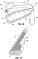
- the insert 640 can fill a percent volume of the cavity 620, as described for golf club head 100. In some embodiments, as illustrated in FIG. 19 , the insert 640 can fill 100% of the cavity 620 and extend into the rear opening 680. As illustrated in FIG. 20 , the insert 640 can fill 60% of the cavity 620. As illustrated in FIG. 21 , the insert 640 can fill 70% of the cavity 620 and extend partially into the rear opening 680. As illustrated in FIG. 22 , the insert 640 can fill 80% of the cavity 620 and extend partially into the rear opening 680. As illustrated in FIG.
- the insert 640 can fill 90% of the cavity 620 and extend partially into the rear opening 680. In some embodiments, not shown, the insert 640 can fill only the cavity 620 and not fill the rear opening 680. In some embodiments, the insert 640 can comprise a metal material and fill only the cavity 620. In this example embodiment, not shown, the opening wall 682 of the body 610 can taper to blend into the insert 640, providing a less distinct boundary for the rear opening 680.
- the insert 640 is formed prior to insertion into golf club head 600, as described below. In other embodiments, the insert 640 is formed within the cavity 620 of the body 610. In these embodiments, the opening wall 682 that forms the rear opening 680 can serve as a port for the insert 640 to be injected into the cavity 620, as described below.
- a front surface of the body cavity 620 can be enclosed by the faceplate 655.
- the faceplate 655 and the strikeface 611 can be similar to the faceplate 155 and strikeface 611 of golf club head 100.
- the strikeface 611 can be integrally formed with the body 610.
- the strikeface 611 comprises a thickness 612 similar to the thickness 112 of strikeface 111 of golf club head 100.
- the body 610 is partially or fully filled by the insert 640, which is secured within the golf club head 600 by the faceplate 655.
- the cavity 620 further houses a tape layer 150 and/or adhesive, similar to the tape layer 150 and/or adhesive of golf club head 100.
- the golf club head 600 further comprises a shaft tip weight 660, similar to the shaft tip weight 160 of golf club head 100.
- the body 610 further comprises a toe cavity 614 housing a toe weight 661, similar to the toe cavity 114 and toe weight 161 of golf club head 100.
- the golf club head 600 can further comprise a toe screw cavity 663 and a toe screw weight 662 for adjusting swing weighting, as depicted in FIGS. 17 and 18 .
- the toe screw weight can comprise a weight between 2 grams and 15 grams, as described for the optional toe screw weight of golf club head 100.
- the toe screw weight 662 can be removed and replaced with a different screw weight 662 having a different weight value to customize the golf club head 600 to a golfer's swing.
- the materials used to form the components of golf club head 600 can be similar to the materials used to form the components of golf club head 100, as described above.
- the body 610 can comprise the same body material as body 110.
- the insert 640 can comprise the same insert material as insert 140.
- the faceplate 655 can comprise the same faceplate material as faceplate 155.
- the toe weight 661, tip weight 660, and toe screw weight 662 can comprise the same materials as the toe weight 161, tip weight 160, and toe screw weight materials as golf club head 100.
- the golf club head 100, 600 can be a tour iron.
- the golf club heads 100, 600 described herein can be a tour iron head comprising a blade length, a hosel-x length, an offset distance, and an upper portion depth characteristic of tour iron.
- the golf club head 100 comprises a blade length 173.
- the blade length 173 is measured as the maximum distance from an edge of the strikeface 111 in the heel region 102 to an edge of the club head 100 in the toe region 101.
- the blade length of a generic tour iron can be less than 71.12 mm (2.8 inches).
- the blade length of a game-improvement iron is generally greater than 71.12 mm (2.8 inches).
- the blade length 173 of golf club head 100 is less than 71.12 mm (2.8 inches), as is characteristic of a tour iron.
- the blade length 173 of golf club head 100 can be between 55.88 mm and 71.12 mm (2.2 inch and 2.8 inch), 55.88 mm and 60.96 mm (2.2 inch and 2.4 inch), 60.96 mm and 66.04 mm (2.4 inch and 2.6 inch), or 66.04 mm and 71.12 mm (2.6 inch and 2.8 inch).
- a hosel-X length 174 is measured from the centerplane 45 to an intersection of the hosel axis 70 with the lead edge axis 35.
- the hosel-X length of a tour iron is generally less than 38.10 mm (1.5 inches), and the hosel-X length of a game improvement iron is generally greater than 38.10 mm (1.5 inches).
- the hosel-X length of the golf club head 100 is less than 38.10 mm (1.5 inches), as is characteristic of a tour iron.
- the hosel-X length 174 can be between 33.02 mm and 38.10 mm (1.30 inches and 1.50 inches), 33.02 mm and 35.56 mm (1.30 inches and 1.40 inches), or 35.56 mm and 38.10 mm (1.40 inches and 1.50 inches).
- an offset distance 173 is measured between a forward edge of the hosel 105 to a forwardmost point of the golf club head 100.
- the forwardmost point is located at the bottom of the strikeface 111 and adjacent the sole 107.
- the offset distance 172 can vary for golf club heads within the same set due to different loft angles. Therefore, in order to compare sets of irons, an average is taken of the offset distances 173 of all golf clubs within a set.
- the average offset for a tour iron set is generally less than 3.56 mm (0.140 inch).
- the average offset for a game-improvement iron set is generally greater than 3.56 mm (0.140 inch).
- the average offset for a set of golf clubs comprising golf club heads similar to club head 100 is less than 3.56 mm (0.140 inch).
- the offset distance 172 of a single golf club head 100 can be between 2.54 mm and 4.06 mm (0.100 inches and 0.160 inches). In some embodiments, the offset distance can be between 2.54 mm and 2.79 mm (0.100 inch and 0.110 inch), 2.79 mm and 3.05 mm (0.110 inch and 0.120 inch), 3.05 mm and 3.30 mm (0.120 inch and 0.130 inch), 3.30 mm and 3.56 mm (0.130 inch and 0.140 inch), 3.56 mm and 3.81 mm (0.140 inch and 0.150 inch), or 3.81 mm and 4.06 mm (0.150 inch and 0.160 inch).
- An upper portion depth 116 is measured adjacent the top rail 106 and orthogonal to the strikeface 111 from the front 104 to the rear 103, as shown in FIG. 4 .
- the average upper portion depth of a tour iron is generally less than 7.37 mm (0.290 inch).
- the average upper portion depth of a game improvement iron is generally greater than 7.37 mm (0.290 inch).
- the average upper portion depth for a set of golf clubs comprising golf club heads similar to golf club head 100 is less than 7.37 mm (0.290 inch), as is characteristic of a set of tour irons.
- a parameter that is similar between game-improvement and tour irons is the height of the golf club head.
- the golf club head 100 can each have a maximum height 175 measured along the loft plane 20 from the lead edge axis 35 to the highest point on the top rail 106.
- Golf club head 600 can have a similar height golf club head 100.
- the maximum height 175 can be between 50.8 mm and 63.5 mm (2.0 inches and 2.5 inches).
- the maximum height 175 can be between 50.8 mm and 53.34 mm (2.0 inches and 2.1 inches), 53.34 mm and 55.88 mm (2.1 inches and 2.2 inches), 55.88 mm and 58.42 mm (2.2 inches and 2.3 inches), 58.42 mm and 60.96 mm (2.3 inches and 2.4 inches), and 60.96 mm and 63.5 mm (2.4 inches and 2.5 inches).
- Table I compares blade length, hosel X, average offset, average upper portion depth, and maximum height of a tour iron versus a game improvement iron. Wherein inch corresponds to 2,54 cm. Table I. Blade Length Hosel X Offset (AVG of All Lofts) Upper Portion Depth (AVG of All Lofts) Maximum Height Tour Iron ⁇ 2.8" ⁇ 1.5" ⁇ 0.140" ⁇ 0.290" 2.0" - 2.5" Game Improvement >2.8" >1.5" >0.140" >0.290" 2.0" - 2.5"
- the CG 60 of the golf club head 100, 600 was shifted down and back compared to a flat back tour iron.
- the CG 60 position of the golf club head 100 can also be measured from the lead edge plane.
- the CG 60 of the golf club heads 100, 600 can be located above the lead edge plane by between 9.65 mm and 17.02 mm (0.380 inch and 0.670 inch). In some embodiments, the CG 60 of the golf club heads 100, 600 can be located above the lead edge plane by between 10.16 mm and 16.51 mm (0.400 inch and 0.650 inch), 9.65 mm and 10.16 mm (0.380 inch and 0.400 inch), 10.16 mm and 10.67 mm (0.400 inch and 0.420 inch), 10.67 mm and 11.18 mm (0.420 inch and 0.440), 11.18 mm and 11.68 mm (0.440 inch and 0.460 inch), 11.68 mm and 12.19 mm (0.460 inch and 0.480 inch), 12.19 mm and 12.70 mm (0.480 inch and 0.500 inch), 12.70 mm and 13.21 mm (0.500 inch and 0.520 inch), 13.21 mm and 13.72 mm (0.520 inch and 0.540 inch), 13.72 mm and 14.22 mm (0.540 inch and 0.560 inch), 14.22 mm and 14.
- the CG 60 can be located above the lead edge plane by 9.65 mm (0.380 inch), 9.91 mm (0.390 inch), 10.16 mm (0.400 inch), 10.41 mm (0.410 inch), 10.67 mm (0.420 inch), 10.92 mm (0.430 inch), 11.18 mm (0.440 inch), 11.43 mm (0.450 inch), 11.68 mm (0.460 inch), 11.94 mm (0.470 inch), 12.19 mm (0.480 inch), 12.45 mm (0.490 inch), 12.70 mm (0.500 inch), 12.95 mm (0.510 inch), 13.21 mm (0.520 inch), 13.46 mm (0.530 inch), 13.72 mm (0.540 inch), 13.97 mm (0.550 inch), 14.22 mm (0.560 inch), 14.48 mm (0.570 inch), 14.73 mm (0.580 inch), 14.99 mm (0.590 inch), 15.24 mm (0.600 inch), 15.49 mm (0.610 inch), 15.75 mm (0.620 inch), 16.00 mm (0.630 inch), 16.26
- the golf club heads 100 and 600 described herein can comprise light weight inserts 140, 440, and 640 in the center of the golf club heads. These weights can be added to the perimeter of the golf club heads 100 and 600 without greatly changing the overall weight of the golf club heads 100, 600, but does allow for a shifting of the CG 60, and raising MOI.
- This perimeter weighting can come in the form of toe weights, a tip weight, or added body material around the perimeter.
- the compact nature of the golf club heads 100 and 600 leads to material properties playing a greater role in MOI improvement than structural properties.
- the MOI about the CG 60 and about the x-axis 30, Ixx can range from 0.05 gram metres squared to 0.077 gram metres squared (78 to 120 gram square inches).
- the MOI about the CG 60 and about the y-axis 40, Iyy can range from 0.2 gram metres squared to 0.3 gram metres squared (310 to 466 gram square inches).
- These MOI values can apply to golf club head 100 and 600.
- These MOI values can further apply to any embodiment having insert 140, 640, or multi-material insert 440.
- a method 500 of manufacturing the golf club head 100 comprises providing each component 510, placing the insert in the body 520, swedging (swagging) the faceplate onto the body 530, laser welding a boundary between the faceplate and the body 540, and cleaning up the final product through grinding and polishing.
- the method 500 can consist of steps 510, 520, 530 and 550.
- Step 510 can comprise providing at least a body 110, an insert 140 or a multi-material insert 440, and a faceplate 155 as components for the golf club head 100.
- providing the body 110 can consist of one or more of: forging, casting, forming by additive manufacturing, machining, or any other suitable method for forming the body 110.
- Step 510 can comprise forming the body 110 as a unitary piece.
- providing the insert 140 can consist of one or more of: forging, casting, forming by additive manufacturing, machining, or any other suitable method for forming the body 140.
- the insert 140 or a portion of the multi-material insert 440 is molded by pouring a resin into a fiber reinforcing structure to form an elastomeric matrix composite.
- the insert 140 can be formed as a unitary piece having a uniform density or as multiple pieces having different densities.
- having the multi-material insert 440 the insert 440 can be formed into a single unit or can be placed into the cavity 120 in two separate portions.
- providing the multi-material insert 440 comprises (1) providing a first portion 450 of the insert 440, (2) providing a second portion 460 of the insert 440, and (3) joining the first and second portions 450, 460 of the insert 440.
- Providing the first portion 450 of the insert 440 can comprise molding the first portion 440.
- Providing the second portion 460 of the insert 440 can comprise casting, forging, stamping, die casting, or other means of providing the second portion 460.
- the sub-steps of (1) providing the second portion 460 and (2) joining the first and second portions 450, 460 are combined when the first portion 450 is molded and joined to the second portion 460.
- the insert 440 may be sanded, ground, or polished before being inserted into the cavity 120 of the golf club head 100.
- forming the faceplate 155 can consist of forging, casting, machining, forming by additive manufacturing, or otherwise forming the faceplate 155. In some embodiments, forming the faceplate 155 can comprise machining, casting, or forging a variable thickness geometry into the faceplate 155.
- step 510 of method 500 can further comprise providing a toe weight, a tip weight, and/or a toe screw weight.
- step 510 further comprises welding the toe weight 161 into a toe cavity 114 of the body 110.
- the toe weight 161 can be swedged (swaged), adhered, or otherwise secured onto the body 610.
- the toe screw weight can be screwed into the golf club head in step 510, 520, 530, or 550.
- Step 520 of the method 500 comprises placing the insert 140 in a cavity 120 of the body 110.
- the insert 140 is inserted through a front opening of the cavity 120 at a front 104 of the body 110.
- this step 520 involves applying adhesive, such as epoxy, to the cavity 120 of the body 110 and to the insert 140 to secure the insert 140 into the body 110.
- this step 520 involves applying one more tape layers, such as tape layer 150, to the cavity 120 before placing the insert 140 into the cavity.
- the one or more tape layers, such as tape layer 150 can form a strong and durable connection between the insert 140 and the cavity 120 of the body 110. Furthermore, the use of tape can reduce the possibility for rattling and other undesirable quality issues.
- various other methods of fastening the insert 140 to the body 110 are combined for maximum security. Not all embodiments of the method 500 require adhering or securing the insert 140 into the cavity 120.
- Step 530 of method 500 comprises securing the faceplate 155 onto the body 110.
- the faceplate 155 is placed within the indentation 142.
- the faceplate 155 is positioned so that it covers the insert 140 and the cavity 120 of the body 110.
- Step 530 can further comprise swedging (swagging) the faceplate 155 onto the body 110 so that the faceplate 155 is embedded in the indentation 142 on the front 104 of the body 110.
- the insert 140 is held within the golf club head 100 and completely isolated from the outside of the golf club head 100.
- the faceplate 155 is adhered, press-fit, or otherwise secured to the body.
- Some golf club heads are manufactured by methods including co-forging (also known as integrated forging) and joining individually cast parts by high temperature and high applied pressure. These methods apply high temperatures which affect multiple components of the golf club head, including any inserts.
- co-forging also known as integrated forging
- the co-forging process occurs at temperatures between 700 and 1000 degrees Celsius.
- the melting point of some aluminum alloys falls between 650 and 680 degrees Celsius.
- co-forging would ruin the integrity of the aluminum material.
- the insert 140, 440, the body 110, and the faceplate 155 are not co-forged together, because co-forging can lead to high temperatures which can compromise the insert 140, 440.
- TIG welding a faceplate onto the golf club head could also impart high temperatures to the golf club head which could compromise the insert.
- the possible materials for a low-density center of an iron-type golf club head are significantly limited due to conventional manufacturing processes.
- the golf club head 100 can be manufactured with a wide variety of insert materials, because the manufacturing process does not place the final assembly under high temperatures.
- some insert materials described herein, such as a thermoplastic composite simply cannot be co-forged with a metal body material.
- the manufacturing method 500 described herein allows the insert 140, 440 to be formed from any suitable material without requiring that the material be able to be co-forged with the body 110.
- Step 530 and step 540 both employ low-heat methods of securing the faceplate 155 to enclose the insert 140 within the cavity 120. Swedging, laser welding, and other low temperature methods of securing the faceplate 155 allow the insert 140 or 440 to comprise a wide variety of materials in order to fine-tune acoustics, feel, and weighting.
- the low-head methods of steps 530 and 540 further allow versatility in the design, such as the use of adhesives and/or tape around the cavity 120 to reduce unwanted rattling and vibration.
- Step 540 comprises laser welding a boundary between the faceplate 155 and the body 110.
- the process of step 540 is also referred to as surface fusion treatment.
- the overlapping region or boundary between the faceplate 155 and the body 110 is laser welded.
- This laser welding process blends the metal materials of the faceplate 155 and the body 110 without creating a deep heat affected zone (hereafter "HAZ").
- Laser welding the boundary eliminates any cracks or seams between the faceplate 155 and the body 110.
- the golf club head 100 is finished with a coating in step 550, as described below. If the boundary has even minute cracks or seams, the coating can seep into the seams and cause quality issues. Laser welding the boundary in step 540 eliminates this manufacturing issue.
- Step 540 described above, can be conducted without compromising the integrity of the materials within the cavity 120 because the HAZ depth is between 0.76 mm and 2.03 mm (0.03 inch and 0.08 inch), which can be less than the thickness 112 of the faceplate 155.
- the HAZ depth can be less than 2.03 mm (0.08 inch), less than 1.78 mm (0.07 inch), less than 1.52 mm (0.06 inch), less than 1.27 mm (0.05 inch), less than 1.02 mm (0.04 inch), or less than 0.76 mm (0.03 inch).
- the HAZ depth can be 0.76 mm (0.03 inch), 1.02 mm (0.04 inch), 1.27 mm (0.05 inch), 1.52 mm (0.06 inch), 1.78 mm (0.07 inch), or 2.03 mm (0.08 inch).
- Laser welding heats the insert and other cavity fillers, such as tape layer(s), to a temperature that is lower than a melting temperature of the insert material. The heat imparted to the golf club head 100 during step 540 does not compromise any of the materials sealed within the cavity 120.
- step 550 of the method 550 the golf club head 100 is cleaned up through grinding and polishing. Grinding is used to create a smooth surface on the strikeface 111 of the golf club head 100. Furthermore, this step 550 can comprise polishing the surface of the golf club head 100 after grinding. In some embodiments, grooves are ground into the strikeface 111 of the faceplate 155, and the strikeface 111 is thereafter polished. No step in the manufacturing method 500 comprises co-forging with different materials.
- a method 700 of manufacturing a golf club head comprises providing at least a body 610, an insert material, a faceplate 655, welding or swedging the faceplate 655 onto the body 610, injecting an insert material into the cavity 620 of the body 610, and polishing and cleaning the golf club head 600.
- the body 610 can be forged, cast, or formed by additive manufacturing.
- the faceplate 655 can be forged, cast, or formed by additive manufacturing.
- the strikeface 655 is integrally formed as part of the body 610 rather than being separately formed as a faceplate 655 and welded or swedged onto a front opening of the body 610.
- step 710 of method 700 further comprises providing a toe weight 661, a tip weight 650, and/or a toe screw weight 662. In these embodiments, step 710 further comprises welding the toe weight 661 into a toe cavity 614 of the body 610.
- the toe weight 661 can be swedged (swaged), adhered, or otherwise secured onto the body 610.
- the toe screw weight 662 can be screwed into the golf club head in step 710, 720, 730, or 750.
- an opening wall 782 defining a rear opening 680 can either be formed into the body 610 or can be cut into the rear 603 of the body 610 after the body 610 is formed.
- Step 710 can further comprise polishing or finishing the opening wall 782 of the rear 603.
- Step 720 comprises placing the faceplate 655 within an indentation 642 of the body.
- the faceplate 655 is welded, swedged (swaged), or otherwise secured to the body 610.
- the body 610 and strikeplate 655 form a cavity 620.
- the only opening to the cavity 620 is the rear opening 680 of the body 610, as illustrated for the embodiment of FIGS. 14-23 .
- step 720 of method 700 can further comprise a laser welding or surface fusion treatment process, similar to that described in step 540 of method 500 above.
- the insert material is injected, in liquid form, into the cavity 620 through the opening 60 in the rear.
- the cavity 620 of the body 610 serves as a mold for the injected material.
- the injection molding process results in the insert material bonding to the surfaces of the cavity 620.
- an injection apparatus To inject the material into the cavity 620 under pressure, an injection apparatus must be sealed to the mouth of the rear opening 680.
- the planar surface surrounding the rear opening 680 in the upper portion 608 of the golf club head 600 allows a good seal to be made between the injection apparatus and the body 610 of the golf club head 600.
- the injection apparatus is configured to further form a seal with a portion of the cavity 620 to prevent the material from filling the entire cavity 620.
- Step 740 of the method 700 the golf club head 600 is cleaned up through grinding and polishing. Grinding is used to create a smooth surface on the strikeface 611 of the golf club head 600. Furthermore, this step 740 can comprise polishing the surface of the golf club head 600 after grinding. In some embodiments, grooves are ground into the strikeface 611 of the faceplate 655, and the strikeface 611 is thereafter polished.
- a method of making some embodiments of the golf club head 600 resembles the method 500 more closely than the method 700 described above.
- a method of forming the golf club head 600 wherein the golf club head 600 comprises a metal insert 640 would require placing the insert 640 within the cavity 640 prior to swedging on the faceplate 655.
- the golf club head 100 was measured using several different parameters. The included the blade length 173, hosel-x length 174, the offset distance 172, the upper portion depth 116, and the maximum height 175. These values were compared to a game improvement iron and are both shown in Table II, below. Both the golf club head 100 and the game improvement iron that were measured were 7-irons, having a roughly equivalent loft angle. Table II. Parameters for Example 1. Blade Length Hosel X Offset Upper Portion Depth Maximum Height Golf club head 100 2.727" 1.345” 0.085" 0.250" 2.040" Game Improvement 2.802" 1.630" 0.175" 0.315" 2.045”
- the traditional tour iron head used in this comparison test is identical in size and headweight to the sample golf club head.
- this test isolated the MOI as a variable, to provide an accurate comparison of the performance of the sample over the traditional tour iron head.
- the test produced an Ixx value of roughly 0.070 gram square meters (108 gram square inches) for the sample club head and an Ixx value of roughly 0.066 gram square meters (103 gram square inches) for the traditional tour iron head. Therefore, the MOI around the x-axis 30 is approximately 4.8% higher in the sample club head.
- the test produced an Iyy value of roughly 0.266 gram square metres (413 gram square inches) for the sample club head and an Iyy value of roughly 0.257 gram square metres (398 gram square inches) for the traditional tour iron head. Therefore, the MOI around the y-axis 40 is approximately 3.7% higher in the sample club head.
- This test shows that the lightweight insert for the golf club head 100 provides an improvement in MOI without altering the size or weight of the golf club head 100.
- MOI Comparison Data for Example 2 Club Head Mass (g) MOIxx MOIyy MOIxx efficiency MOIyy efficiency (1) Filled with TPC (opening in rear) 265.0 97.4 414.4 0.368 1.564 (2) Filled with Aluminum (opening in rear) 278.0 100.0 421.8 0.360 1.517 (3) Filled with TPC (enclosed cavity) 254.1 96.1 410.3 0.378 1.615 (4) Filled with Aluminum (enclosed cavity) 265.0 98.0 415.5 0.370 1.568 (5) Solid Steel 314.0 106.6 438.8 0.340 1.398
- MOI is a function of distance from the CG and mass
- the MOI will reflect changes in the overall mass of the golf club head. Therefore, to accurately compare club head MOI, the difference in total mass of the golf club head must be accounted for.
- MOI efficiency value of golf club heads can be compared, independent of mass, to show how the structure and localized weighting of the golf club heads affects the MOI.
- the MOI values in both the x-axis 30 and the y-axis 40 directions were higher for the solid steel golf club head (5) than for the low-density insert golf club heads (1) through (4), the MOI efficiency of the solid steel golf club head (5) was lower than the MOI efficiency of golf club heads (1) through (4). Therefore, the golf club heads (1) through (4) with low-density inserts are more forgiving than a golf club head lacking the low-density insert 140, 440, 460 of the golf club head 100, 600 described herein.
- the golf club heads (1) through (4) with low-density inserts have MOI efficiencies in the x-axis 30 direction of 5.9% to 11.2% higher than solid steel golf club head (5).
- the club heads (1) through (4) with low-density inserts have MOI efficiencies in the y-axis 40 direction of 8.5% to 15.5% higher than solid steel golf club head (5).
- the golf club heads 100, 600 described herein comprise a lower CG 60 than an equivalent solid steel iron having a similar shape to golf club heads 100 and 600.
- Lower CG is desirable in tour irons because shots are easier to shape when the CG is lower.
- the lowering of the CG is due in part to the elimination of high-density body material by inclusion of the opening 680 in the rear 603. Table IV.
- the CGy is measured in the y-axis 40 direction (vertical) and upward from the lead edge axis 35.
- the CGx is measured horizontally along the lead edge axis 35 with the origin at the y-axis 40, such that the CG is closer to the heel 102 when the CGx value is positive.
- the CGz is measured rearward, horizontally along the z-axis 50 from the lead edge axis 35.
- the CGy value is lower in golf club heads 1 and 2 than in golf club heads 3-5. This shows that the golf club heads having the opening in the rear of the body (similar to golf club head 600, described above) have a desirably lower CG.
- the CG is 2.06% lower in club head 2 than in steel club head 5.
- the CG is 2.84% lower in golf club head 1 than in steel golf club head 5, indicating that the low-density TPC insert results in an even better CG placement than it's aluminum insert counterpart (golf club head 2).
- the comparison data in Tables III and IV further illustrates the strengths of the enclosed cavity embodiments and the rear opening embodiments. Although all embodiments of the invention (comparison golf club heads (1) through (4)) show improvements over the solid club head (5), both the enclosed cavity embodiments (comparison golf club heads (3) and (4)) and the rear opening embodiments (comparison golf club heads (1) and (2)) provide unique benefits.
- the comparison data shows that the MOI efficiency in both the x-axis 30 direction and the y-axis 40 direction is higher in the enclosed cavity club heads (3) and (4) than in the club heads (1), (2), and (5), as shown in the MOI efficiency columns of Table II.
- the enclosed cavity embodiments similar to golf club heads 100 described herein or comparison club heads (3) and (4), are more forgiving than embodiments having an opening in the rear, such as golf club head 600 or comparison club heads (1) and (2).
- embodiments with a rear opening 680 in the body 610 have lower CG values than the embodiments having an enclosed cavity, as shown in the CGy column of Table IV.
- the location of the CG of a golf club head affects performance.
- the CG location affects the amount of torque that is imparted to the golf club head upon impact with a golf ball.
- the arm between the force applied by the golf ball and the CG is lessened, since the golf ball is typically struck with a lower portion of the strikeface.
- This shortened arm between the applied force and the CG results in lower torque and improved launch characteristics upon impact with a golf ball. Therefore, in order to provide the golfer with the best possible experience, the golf club head described herein comprises a low CG.
- the CGy value which is measured along the vertical y-axis 40, is significantly lower for the golf club head similar to 100 and 600.
- the golf club head similar to 100 and 600 comprises a CGy 0.991 mm (0.039 inch) lower than the comparison golf club head. This shows that the uniform depth of the upper portion 108, 608 above the inflection point 130, 630, lowers the CG, providing better launch and spin characteristics and higher ball speed.
- the CGz value is measured along the z-axis 50, wherein rearward of the CG 60 is negative and forward of the CG 60 is positive.
- the CG 60 of the golf club head similar to 100 and 600 is closer to the front of the golf club head.
- a survey has been conducted to quantify the feel of a sample tour iron, having a golf club head similar to the golf club head 100 described herein. Twenty golfers participated in the survey and compared their experiences with the sample iron to their experiences with a traditional tour iron. After using both the sample and the traditional iron, survey participants were asked the following question for each iron: "How satisfied are you with the impact experience (feel/sound) that this iron provides?" A majority of the players preferred the impact experience of the sample tour iron over the traditional tour iron.
- the strikeface 111 and 611 is engineered to withstand, alone, the stresses placed on it by striking a golf ball.
- the inclusion of the thermoplastic composite insert 140, 640, the fully metal insert 140, 640, or the multi-material insert 440 gives the golf club head an additionally solid feel and improves the acoustic quality of the golf club head over similar hollow-bodied golf club heads.
- the faceplate 155, 655 can improve the quality and durability of the golf club head by ensuring that the insert 140, 640 remains secured inside the golf club head at all times.
- the golf club head 100, 600 described herein fills a need in the art for an iron type club head that marries the reliability of a game-improvement iron with the elegance of a tour iron.
- the golf club heads 100 and 600 described herein functions as tour type golf club heads. They offer a high MOI while remaining smaller than typical game-improvement irons. These multi-material golf club heads 100 and 600 offer a compact product with exceptional forgiveness.
- FIGS. 1-23 depict specific embodiments of golf club heads, the disclosure of embodiments is intended to be illustrative of the scope of the present disclosure and is not intended to be limiting. It is intended that the scope of the present disclosure shall be limited only to the extent required by the appended claims.
- golf equipment related to the methods, apparatus, and/or articles of manufacture described herein may be conforming or non-conforming to the rules of golf at any particular time. Accordingly, golf equipment related to the methods, apparatus, and/or articles of manufacture described herein may be advertised, offered for sale, and/or sold as conforming or non-conforming golf equipment.
- the methods, apparatus, and/or articles of manufacture described herein are not limited in this regard.
Landscapes
- Health & Medical Sciences (AREA)
- General Health & Medical Sciences (AREA)
- Physical Education & Sports Medicine (AREA)
- Golf Clubs (AREA)
Claims (17)
- Golfschlägerkopf (100), umfassend:einen Massenschwerpunkt (60), eine Frontplatte (155), einen Körper (110) und einen Einsatz (140);wobei der Körper einen oberen Abschnitt (108), einen unteren Abschnitt (109), eine Sohle (107), eine Rückseite (103), eine Ferse (102), eine Zehe (101) und eine obere Schiene (106) umfasst;wobei:die Frontplatte und ein Abschnitt des Körpers eine Schlagfläche des Golfschlägerkopfes definieren;die Frontplatte, die Sohle, die Rückseite und die obere Schiene einen Hohlraum (120) umschließen;der Hohlraum ein Volumen zwischen 17 % und 32 % des Schlägerkopfvolumens aufweist;die Rückseite eine Biegungssicke (130) umfasst;die Sohle auf einer Bodenebene (10) ruht;eine Loftebene (20) tangential zur Frontplatte ist und die Bodenebene schneidet;eine Mittelebene (45), die senkrecht zur Bodenebene, senkrecht zur Loftebene und koinzident mit einem Mittelpunkt (80) der Schlagfläche ist;der obere Abschnitt durch die obere Schiene und die Biegungssicke begrenzt ist;der obere Abschnitt eine Höhe, gemessen entlang der Mittelebene von der oberen Schiene bis zur Biegungssicke, in einer Richtung parallel zur Loftebene aufweist;der untere Abschnitt eine Höhe, gemessen entlang der Mittelebene von der Sohle bis zur Biegungssicke, in einer Richtung parallel zur Loftebene aufweist;die Höhe des oberen Abschnitts und die Höhe des unteren Abschnitts ein Verhältnis zwischen 9:8 und 6:11 aufweisen;der obere Abschnitt eine erste Tiefe (116) umfasst und der untere Abschnitt eine zweite Tiefe (118) umfasst, wobei die Tiefen senkrecht zur Loftebene, von der Schlagfläche zu einer Außenfläche der Rückseite, entlang der Mittelebene gemessen sind;die erste Tiefe konstant und geringer als die zweite Tiefe ist;die Sohle, die Rückseite, die obere Schiene und die Frontplatte den Hohlraum umschließen;der Einsatz im Hohlraum aufgenommen ist und der Einsatz 90 % oder mehr des Hohlraums ergänzt;die Frontplatte ein erstes Material mit einer ersten Dichte umfasst;der Körper ein zweites Material mit einer zweiten Dichte umfasst;der Einsatz ein drittes Material mit einer dritten Dichte umfasst; unddie dritte Dichte geringer ist als die erste und die zweite Dichte;ein Band zwischen dem Einsatz und der Frontplatte angeordnet ist, um den Einsatz auf der Frontplatte zu befestigen;eine x-Achse (30), die sich in einer Ferse-zu-Zehen-Richtung parallel zur Schlagfläche erstreckt und mit dem Massenschwerpunkt des Schlägerkopfes koinzident ist;eine y-Achse (40), die orthogonal zur Bodenebene ist und mit dem Massenschwerpunkt koinzident ist;wobei:ein Trägheitsmoment, Ixx, gemessen um die x-Achse, in einem Bereich von 0,05 Gramm pro Quadratmeter (78 Gramm pro Quadratzoll) und 0,077 Gramm pro Quadratmeter (120 Gramm pro Quadratzoll) liegt; undein Trägheitsmoment, Iyy, gemessen um die y-Achse, in einem Bereich von 0,2 Gramm pro Quadratmeter (310 Gramm pro Quadratzoll) und 0,3 Gramm pro Quadratmeter (466 Gramm pro Quadratzoll) liegt.
- Golfschlägerkopf nach Anspruch 1, wobei die dritte Dichte zwischen 2,4 und 5,0 g/cm3 beträgt.
- Golfschlägerkopf nach Anspruch 2, wobei das dritte Material ein Material ausgewählt aus der Gruppe bestehend aus Aluminium und Titan umfasst.
- Golfschlägerkopf nach Anspruch 1, wobei die erste Dichte zwischen 2,6 und 8.7 g/cm3 und die zweite Dichte zwischen 7,7 und 8,1 g/cm3 beträgt.
- Golfschlägerkopf nach Anspruch 4, wobeidas erste Material ein Material umfasst, das aus der Gruppe bestehend aus folgenden ausgewählt ist: einem Material auf Stahlbasis, einem Material auf Titanbasis, einer Aluminiumlegierung oder einer Titanlegierung;das zweite Material ein Material umfasst, das aus der Gruppe bestehend aus folgenden ausgewählt ist: einem Material auf Stahlbasis oder einer Stahllegierung.
- Golfschlägerkopf nach Anspruch 1, ferner umfassend:eine Gesamtmasse;ein Zehengewicht (161);wobei:der Körper ferner Folgendes umfasst: einen Zehenhohlraum (114);der Zehenhohlraum das Zehengewicht aufnimmt; unddas Zehengewicht eine Masse zwischen 5 % und 45 % der Gesamtmasse des Schlägerkopfes umfasst.
- Golfschlägerkopf nach Anspruch 1, wobei ein Verhältnis der ersten Tiefe zu einem Maximum der zweiten Tiefe zwischen 1:3 und 4:5 beträgt.
- Golfschlägerkopf nach Anspruch 1, ferner umfassend:eine Leitkantenachse parallel zur Bodenebene, die sich in Ferse-zu-Zehen-Richtung erstreckt und mit einem Punkt auf der Mittelebene koinzident ist, die auf der Schlagfläche am tiefsten liegt;einen Leitkantenebene parallel zur Bodenebene und die mit der Leitkantenachse koinzident ist;wobei der Massenschwerpunkt des Golfschlägerkopfes zwischen 9,65 mm (0,380 Zoll) und 17,02 mm (0,670 Zoll) über der Leitkantenebene angeordnet ist.
- Golfschlägerkopf nach Anspruch 1, ferner umfassend:einen zylindrischen Hosel (150), der in den Körper integriert ist;eine Hoselreferenzebene, die von einer Zehenseite aus betrachtet parallel zu einer Vorderkante des zylindrischen Hosels ist;eine Hoselachse (70), die als Mittelachse des zylindrischen Hosels definiert ist;eine Leitkantenachse parallel zur Bodenebene, die sich in eine Ferse-zu-Zehen-Richtung erstreckt und mit einem Punkt auf der Mittelebene, der auf der Schlagfläche am tiefsten liegt, koinzident ist;einen Hosel-X-Abstand, von vorne betrachtet vom Schnittpunkt der Leitkantenachse mit der Mittelebene bis zum Schnittpunkt der Leitkantenachse mit der Hoselachse gemessen, wobei der Hosel-X-Abstand weniger als 38,1 mm (1,5 Zoll) beträgt; undein Versatzabstand, gemessen als Mindestabstand zwischen der Leitkantenachse und der Hoselbezugsebene; wobei der Versatzabstand zwischen 1,27 mm (0,05 Zoll) und 6,86 mm (0,27 Zoll) beträgt.
- Golfschlägerkopf nach Anspruch 1, ferner umfassend:
eine Blade-Länge, gemessen in Ferse-zu-Zehen-Richtung von einer Kante der Schlagfläche in der Ferse zu einem äußersten Punkt auf der Zehe; wobei die Blade-Länge weniger als 71,12 mm (2,8 Zoll) beträgt. - Golfschlägerkopf nach Anspruch 1, wobei die Frontplatte zum Körper auf den Körper tiefgezogen und eine Grenze zwischen der Frontplatte und dem Körper lasergeschweißt ist.
- Golfschlägerkopf nach Anspruch 1, wobei:der Körper ferner eine Einrückung (142) umfasst;die Einrückung an einen Umfang des Hohlraums angrenzt;ein Bereich der Rückseite der Frontplatte mit dem Einsatz in Kontakt ist;ein Restbereich der Rückseite der Frontplatte mit der Einrückung in Kontakt ist.
- Verfahren zum Ausbilden des Golfschlägerkopfes (100) nach Anspruch 1, das folgende Schritte umfasst:(1) Bereitstellen einer Frontplatte (155), die ein erstes Material mit einer ersten Dichte umfasst;(2) Bereitstellen eines Körpers (110), der ein zweites Material mit einer zweiten Dichte, einen oberen Abschnitt (108), einen unteren Abschnitt (109), eine Sohle (107), eine Rückseite (103), eine Zehe (101), eine Ferse (102), und eine obere Schiene (106) umfasst; wobei:die Frontplatte und ein Abschnitt des Körpers eine Schlagfläche des Golfschlägerkopfes definieren;die Rückseite eine Biegungssicke (130) umfasst;die Sohle auf einer Bodenebene (10) ruht;eine Loftebene (20) tangential zur Frontplatte ist und die Bodenebene schneidet;eine Mittelebene (45), die senkrecht zur Bodenebene ist, sich in eine Obere-Schiene-zu-Sohlen-Richtung erstreckt und koinzident mit einem Mittelpunkt (80) der Schlagfläche ist;der obere Abschnitt durch die obere Schiene und die Biegungssicke begrenzt ist;der obere Abschnitt eine Höhe, gemessen entlang der Mittelebene von der oberen Schiene bis zur Biegungssicke, in einer Richtung parallel zur Loftebene aufweist;der untere Abschnitt eine Höhe, gemessen entlang der Mittelebene von der Sohle bis zur Biegungssicke, in einer Richtung parallel zur Loftebene aufweist;die Höhe des oberen Abschnitts und die Höhe des unteren Abschnitts ein Verhältnis zwischen 9:8 und 6:11 aufweisen;der obere Abschnitt eine erste Tiefe (116) umfasst und der untere Abschnitt eine zweite Tiefe (118) umfasst, wobei die Tiefen senkrecht zur Loftebene, von der Schlagfläche zu einer Außenfläche der Rückseite, entlang der Mittelebene gemessen sind;die erste Tiefe konstant und geringer als die zweite Tiefe ist;die Sohle, die Rückseite und die obere Schiene einen Hohlraum definieren;(3) Bereitstellen eines Einsatzes (140), der ein drittes Material mit einer dritten Dichte umfasst, wobei die dritte Dichte geringer ist als die erste und die zweite Dichte; und(4) Anordnen des Einsatzes innerhalb des Hohlraums (120); woraufhin der Einsatz 90 % oder mehr des Hohlraums ergänzt und der Hohlraum ein Volumen zwischen 17 % und 32 % des Golfschlägervolumens umfasst; und(5) Befestigen der Frontplatte auf dem Körper, wobei die Frontplatte ferner den Hohlraum definiert und umschließt;wobei der Golfkopfschläger Folgendes umfasst:eine x-Achse (30), die sich in einer Ferse-zu-Zehen-Richtung parallel zur Schlagfläche erstreckt und mit einem Massenschwerpunkt des Schlägerkopfes koinzident ist;eine y-Achse (40), die orthogonal zur Bodenebene ist und mit dem Massenschwerpunkt koinzident ist;wobei:ein Trägheitsmoment, Ixx, gemessen um die x-Achse, in einem Bereich von 0,05 Gramm pro Quadratmeter (78 Gramm pro Quadratzoll) und 0,077 Gramm pro Quadratmeter (120 Gramm pro Quadratzoll) liegt; undein Trägheitsmoment, Iyy, gemessen um die y-Achse, in einem Bereich von 0,2 Gramm pro Quadratmeter (310 Gramm pro Quadratzoll) und 0,3 Gramm pro Quadratmeter (466 Gramm pro Quadratzoll) liegt;wobei das Verfahren ferner zwischen Schritt (4) und (5) das Anordnen einer Bandschicht auf dem Einsatz umfasst, wobei die Bandschicht nach Abschluss von Schritt (5) sandwichartig zwischen dem Einsatz und der Frontplatte angeordnet ist.
- Verfahren zum Ausbilden eines Golfschlägerkopfes nach Anspruch 13, wobei das Befestigen der Frontplatte auf dem Körper in Schritt (5) Folgendes umfasst:Tiefziehen der Frontplatte auf den Körper;Laserschweißen einer Grenze zwischen der Frontplatte und dem Körper.
- Verfahren zum Ausbilden eines Golfschlägerkopfes nach Anspruch 14, wobei das Laserschweißen der Grenze zwischen der Frontplatte und dem Körper das Erzeugen einer wärmebeaufschlagten Zone mit einer Tiefe von weniger als 1,78 mm (0,070) umfasst.
- Verfahren zum Ausbilden eines Golfschlägerkopfes nach Anspruch 13, wobei:das Verfahren ferner das Ausbilden eines zylindrischen Hosels umfasst, welcher in den Körper integriert ist;wobei der Golfschlägerkopf ferner Folgendes umfasst:eine Hoselreferenzebene, die von einer Zehenseite aus betrachtet parallel zu einer Vorderkante des zylindrischen Hosels ist;eine Hoselachse, die als Mittelachse des zylindrischen Hosels definiert ist;eine Leitkantenachse parallel zur Bodenebene, die sich in einer Ferse-zu-Zehen-Richtung erstreckt und mit einem Punkt auf der Mittelebene, der auf der Schlagfläche am tiefsten liegt, koinzident ist;einen Hosel-X-Abstand, von vorne betrachtet vom Schnittpunkt der Leitkantenachse mit der Mittelebene bis zum Schnittpunkt der Leitkantenachse mit der Hoselachse gemessen, wobei der Hosel-X-Abstand weniger als 38,1 mm (1,5 Zoll) beträgt; undeinen Versatzabstand, gemessen als Mindestabstand zwischen der Leitkantenachse und der Hoselbezugsebene; wobei der Versatzabstand zwischen 1,27 mm (0,05 Zoll) und 6,86 mm (0,27 Zoll) beträgt.
- Verfahren zum Ausbilden eines Golfschlägerkopfes nach Anspruch 13, wobei:der Golfschlägerkopf eine Gesamtmasse umfasst;der Körper ferner einen Zehenhohlraum umfasst; unddas Verfahren ferner Folgendes umfasst:Ausbilden eines Zehengewichts, wobei das Zehengewicht eine Masse zwischen 5 % und 45 % der Gesamtmasse des Golfschlägerkopfes umfasst; undBefestigen des Zehengewichts innerhalb des Zehenhohlraums.
Priority Applications (1)
| Application Number | Priority Date | Filing Date | Title |
|---|---|---|---|
| EP24162786.8A EP4374937B1 (de) | 2018-02-26 | 2019-02-26 | Eisengolfschlägerkopf aus mehreren materialien |
Applications Claiming Priority (4)
| Application Number | Priority Date | Filing Date | Title |
|---|---|---|---|
| US201862635020P | 2018-02-26 | 2018-02-26 | |
| US201862713424P | 2018-08-01 | 2018-08-01 | |
| US201862768543P | 2018-11-16 | 2018-11-16 | |
| PCT/US2019/019661 WO2019165467A1 (en) | 2018-02-26 | 2019-02-26 | Multi-material iron golf club head |
Related Child Applications (2)
| Application Number | Title | Priority Date | Filing Date |
|---|---|---|---|
| EP24162786.8A Division EP4374937B1 (de) | 2018-02-26 | 2019-02-26 | Eisengolfschlägerkopf aus mehreren materialien |
| EP24162786.8A Division-Into EP4374937B1 (de) | 2018-02-26 | 2019-02-26 | Eisengolfschlägerkopf aus mehreren materialien |
Publications (3)
| Publication Number | Publication Date |
|---|---|
| EP3758809A1 EP3758809A1 (de) | 2021-01-06 |
| EP3758809A4 EP3758809A4 (de) | 2021-11-17 |
| EP3758809B1 true EP3758809B1 (de) | 2025-04-09 |
Family
ID=67684967
Family Applications (2)
| Application Number | Title | Priority Date | Filing Date |
|---|---|---|---|
| EP24162786.8A Active EP4374937B1 (de) | 2018-02-26 | 2019-02-26 | Eisengolfschlägerkopf aus mehreren materialien |
| EP19758199.4A Active EP3758809B1 (de) | 2018-02-26 | 2019-02-26 | Eisengolfschlägerkopf aus mehreren materialien |
Family Applications Before (1)
| Application Number | Title | Priority Date | Filing Date |
|---|---|---|---|
| EP24162786.8A Active EP4374937B1 (de) | 2018-02-26 | 2019-02-26 | Eisengolfschlägerkopf aus mehreren materialien |
Country Status (5)
| Country | Link |
|---|---|
| US (3) | US11058931B2 (de) |
| EP (2) | EP4374937B1 (de) |
| JP (3) | JP7203114B2 (de) |
| KR (3) | KR102657844B1 (de) |
| WO (1) | WO2019165467A1 (de) |
Families Citing this family (28)
| Publication number | Priority date | Publication date | Assignee | Title |
|---|---|---|---|---|
| US12576320B2 (en) * | 2009-06-11 | 2026-03-17 | Karsten Manufacturing Corporation | Golf club weight attachment mechanisms and related methods |
| US11684831B2 (en) * | 2017-01-10 | 2023-06-27 | Parsons Xtreme Golf, LLC | Golf club heads and methods to manufacture golf club heads |
| US20230042378A1 (en) * | 2016-07-26 | 2023-02-09 | Acushnet Company | Golf club having a damping element for ball speed control |
| US11938387B2 (en) * | 2016-07-26 | 2024-03-26 | Acushnet Company | Golf club having a damping element for ball speed control |
| US20230166167A1 (en) * | 2016-07-26 | 2023-06-01 | Acushnet Company | Golf club having a damping element for ball speed control |
| US12303750B2 (en) | 2017-01-10 | 2025-05-20 | Parsons Xtreme Golf, LLC | Golf club heads and methods to manufacture golf club heads |
| JP2019176972A (ja) * | 2018-03-30 | 2019-10-17 | 美津濃株式会社 | アイアンゴルフクラブヘッド |
| CN113015563B (zh) * | 2018-11-02 | 2022-05-24 | 帕森斯极致高尔夫有限责任公司 | 高尔夫球杆头和制造高尔夫球杆头的方法 |
| US12434112B2 (en) | 2019-03-11 | 2025-10-07 | Parsons Xtreme Golf, LLC | Golf club heads and methods to manufacture golf club heads |
| US20240149120A1 (en) * | 2019-05-10 | 2024-05-09 | Taylor Made Golf Company, Inc. | Golf club head |
| KR102820247B1 (ko) * | 2019-06-05 | 2025-06-12 | 카스턴 매뉴팩츄어링 코오포레이숀 | 다중 재료 아이언 골프 클럽 헤드 |
| USD928895S1 (en) * | 2019-12-18 | 2021-08-24 | Karsten Manufacturing Corporation | Golf club head |
| JP7581639B2 (ja) * | 2020-03-24 | 2024-11-13 | ヤマハ株式会社 | ゴルフクラブヘッド及びゴルフクラブ |
| US11618213B1 (en) | 2020-04-17 | 2023-04-04 | Cobra Golf Incorporated | Systems and methods for additive manufacturing of a golf club |
| US11130023B1 (en) * | 2020-05-29 | 2021-09-28 | Sumitomo Rubber Industries, Ltd. | Golf club head |
| US11247106B2 (en) * | 2020-07-03 | 2022-02-15 | Sumitomo Rubber Industries, Ltd. | Golf club heads with variable face thickness |
| EP4706790A3 (de) * | 2020-10-30 | 2026-05-06 | Karsten Manufacturing Corporation | Golfschlägerkopf mit einsatz |
| JP7797517B2 (ja) * | 2021-02-02 | 2026-01-13 | カーステン マニュファクチュアリング コーポレーション | インサートを備えたゴルフクラブヘッド |
| US11351427B1 (en) * | 2021-03-12 | 2022-06-07 | Acushnet Company | Hollow co-molded iron with inner lightweight portion |
| KR102519324B1 (ko) * | 2021-11-08 | 2023-04-06 | 파슨스 익스트림 골프, 엘엘씨 | 골프 클럽 헤드 및 골프 클럽 헤드 제조 방법 |
| US20240058661A1 (en) * | 2022-03-11 | 2024-02-22 | Acushnet Company | Golf club head having supported striking face |
| US20240050817A1 (en) * | 2022-03-11 | 2024-02-15 | Acushnet Company | Golf club head having supported striking face |
| US12491416B2 (en) | 2022-09-22 | 2025-12-09 | Karsten Manufacturing Corporation | Iron-type golf club head with rear opening and insert |
| USD1039090S1 (en) | 2022-10-20 | 2024-08-13 | Karsten Manufacturing Corporation | Golf club head |
| TWI812545B (zh) * | 2022-11-16 | 2023-08-11 | 宏利汽車部件股份有限公司 | 高爾夫球桿頭部件的製造方法 |
| JP2026512057A (ja) * | 2023-04-06 | 2026-04-14 | カーステン マニュファクチュアリング コーポレーション | ニューマティックインサートを有するゴルフクラブヘッド |
| KR20250152866A (ko) | 2024-04-17 | 2025-10-24 | 주식회사 엘지에너지솔루션 | 배터리 관리 장치 및 그것의 동작 방법 |
| US20250352867A1 (en) * | 2024-05-14 | 2025-11-20 | Acushnet Company | Golf club head with ball speed control |
Family Cites Families (115)
| Publication number | Priority date | Publication date | Assignee | Title |
|---|---|---|---|---|
| JP2590325B2 (ja) | 1986-09-12 | 1997-03-12 | ブリヂストンスポーツ株式会社 | ゴルフクラブセツト |
| US4883274A (en) | 1987-12-31 | 1989-11-28 | Hsien James C | Golf club head with variable center of gravity |
| JPH082383B2 (ja) | 1988-06-16 | 1996-01-17 | ダイワゴルフ株式会社 | ゴルフクラブヘッドの製造方法 |
| US5198062A (en) | 1992-07-02 | 1993-03-30 | Chen Archer C C | Method of making golf club head |
| US5588923A (en) | 1992-08-05 | 1996-12-31 | Callaway Golf Company | Golf club head with attached selected swing weight composite |
| US5312106A (en) | 1992-10-14 | 1994-05-17 | Cook Don R | Composite weighted golf club heads |
| FR2703913A1 (fr) | 1993-04-16 | 1994-10-21 | Taylor Made Golf Co | Tête de club de golf du type fer amortie. |
| US5429353A (en) | 1993-07-30 | 1995-07-04 | Acushnet Company | Golf club irons and method of manufacture of iron sets |
| US5425535A (en) | 1994-07-20 | 1995-06-20 | Flagler Manufacturing, Inc. | Polymer filled perimeter weighted golf clubs |
| JP3214539B2 (ja) | 1995-09-13 | 2001-10-02 | アルプス電気株式会社 | 磁気記録再生装置のヘッド移送機構 |
| JPH1085372A (ja) * | 1996-09-13 | 1998-04-07 | Honma Golf:Kk | ゴルフクラブ用ヘッド |
| JPH10277186A (ja) * | 1997-04-04 | 1998-10-20 | Yonetsukusu Kk | ゴルフ用アイアンクラブ |
| JP3582812B2 (ja) | 1997-06-16 | 2004-10-27 | 株式会社遠藤製作所 | ゴルフクラブの製造方法 |
| US6042486A (en) | 1997-11-04 | 2000-03-28 | Gallagher; Kenny A. | Golf club head with damping slot and opening to a central cavity behind a floating club face |
| JP3211753B2 (ja) | 1997-11-20 | 2001-09-25 | 株式会社遠藤製作所 | アイアンゴルフクラブ |
| US6093116A (en) | 1998-12-22 | 2000-07-25 | Callaway Golf Company | Golf club head with vibration damping channels |
| US6592469B2 (en) * | 2001-01-25 | 2003-07-15 | Acushnet Company | Golf club heads with back cavity inserts and weighting |
| JP2003052867A (ja) * | 2001-08-10 | 2003-02-25 | Maruman Golf Corp | ゴルフクラブヘッド |
| JP2003245385A (ja) * | 2002-02-21 | 2003-09-02 | Fu Sheng Industrial Co Ltd | ゴルフクラブヘッドと打撃プレートの溶接方法 |
| US6843733B1 (en) | 2002-03-21 | 2005-01-18 | Mizuno Corporation | Cavity back golf club having a multi-tiered weight distribution configuration |
| US6688989B2 (en) | 2002-04-25 | 2004-02-10 | Acushnet Company | Iron club with captive third piece |
| JP2004016737A (ja) * | 2002-06-20 | 2004-01-22 | Bridgestone Sports Co Ltd | アイアン型ゴルフクラブヘッド |
| JP3925360B2 (ja) | 2002-08-30 | 2007-06-06 | ブリヂストンスポーツ株式会社 | ゴルフクラブヘッド |
| US6743117B2 (en) | 2002-09-13 | 2004-06-01 | Acushnet Company | Golf club head with face inserts |
| US6969326B2 (en) * | 2002-12-11 | 2005-11-29 | Taylor Made Golf Company, Inc. | Golf club head |
| US6872153B2 (en) | 2003-06-25 | 2005-03-29 | Acushnet Company | Golf club iron |
| US20050020378A1 (en) | 2003-07-11 | 2005-01-27 | Krumme John F. | Faceplate backings and monolithic inserts for golf clubs |
| US20050014573A1 (en) * | 2003-07-14 | 2005-01-20 | Michael Lee | Golf iron |
| US7004853B2 (en) * | 2003-07-28 | 2006-02-28 | Callaway Golf Company | High density alloy for improved mass properties of an article |
| US6921344B2 (en) | 2003-08-13 | 2005-07-26 | Acushnet Company | Reinforced golf club head having sandwich construction |
| US20050037860A1 (en) | 2003-08-13 | 2005-02-17 | Gilbert Peter J. | Forged iron-type golf clubs |
| US7153222B2 (en) | 2003-08-13 | 2006-12-26 | Acushnet Company | Forged iron-type golf clubs |
| US7166042B2 (en) | 2003-08-13 | 2007-01-23 | Acushnet Company | Forged iron-type golf clubs |
| US7476162B2 (en) | 2003-09-19 | 2009-01-13 | Nike, Inc. | Golf club head having a bridge member and a damping element |
| JP2005130911A (ja) | 2003-10-28 | 2005-05-26 | Nelson Precision Casting Co Ltd | ゴルフクラブヘッドと重りの結合構造 |
| JP2005131283A (ja) | 2003-10-31 | 2005-05-26 | Nelson Precision Casting Co Ltd | ゴルフクラブヘッドの構造 |
| JP4400196B2 (ja) | 2003-12-05 | 2010-01-20 | ブリヂストンスポーツ株式会社 | アイアン型ゴルフクラブヘッド |
| TWI246934B (en) | 2004-03-16 | 2006-01-11 | Wen-Jeng Tzeng | Golf iron club head with ventilation structure |
| US8939848B2 (en) | 2004-05-12 | 2015-01-27 | Cobra Golf Incorporated | Golf club head with top line insert |
| CN101031342B (zh) | 2004-07-26 | 2013-01-02 | 住胶体育用品株式会社 | 带有插入件的背肌式铁杆型高尔夫球杆头 |
| US7722479B2 (en) | 2004-09-22 | 2010-05-25 | Cobra Golf, Inc. | Golf club with deep undercut |
| US8858364B2 (en) * | 2005-03-04 | 2014-10-14 | Taylor Made Golf Company, Inc. | Welded iron-type clubhead with thin high-cor face |
| US7232377B2 (en) | 2005-04-14 | 2007-06-19 | Acushnet Company | Iron-type golf clubs |
| US7559850B2 (en) * | 2005-04-14 | 2009-07-14 | Acushnet Company | Iron-type golf clubs |
| US7192362B2 (en) * | 2005-04-14 | 2007-03-20 | Acushnet Company | Iron-type golf clubs |
| US7371190B2 (en) | 2005-04-14 | 2008-05-13 | Acushnet Company | Iron-type golf clubs |
| TWI286945B (en) | 2005-08-26 | 2007-09-21 | Ming-Shian Chen | Golf club head and manufacturing method thereof |
| US7744487B2 (en) | 2006-03-06 | 2010-06-29 | Nike, Inc. | Golf clubs and golf club heads having feel altering systems |
| TWI307286B (en) * | 2006-05-12 | 2009-03-11 | Metal Ind Res & Dev Ct | Golf head and welding method thereof |
| US20070281796A1 (en) | 2006-05-31 | 2007-12-06 | Gilbert Peter J | Muscle-back iron golf clubs with higher moment of intertia and lower center of gravity |
| US7980960B2 (en) * | 2006-06-09 | 2011-07-19 | Acushnet Company | Iron-type golf clubs |
| US8388464B2 (en) | 2006-06-09 | 2013-03-05 | Acushnet Company | Iron-type golf clubs |
| US7749100B2 (en) | 2006-07-11 | 2010-07-06 | Nike, Inc. | Golf clubs and golf club heads having fluid-filled bladders and/or interior chambers |
| US9586104B2 (en) | 2006-07-21 | 2017-03-07 | Cobra Golf Incorporated | Multi-material golf club head |
| US7922604B2 (en) | 2006-07-21 | 2011-04-12 | Cobra Golf Incorporated | Multi-material golf club head |
| US8870682B2 (en) * | 2006-07-21 | 2014-10-28 | Cobra Golf Incorporated | Multi-material golf club head |
| US7621822B2 (en) * | 2006-09-01 | 2009-11-24 | Acushnet Company | Iron golf club with improved mass properties and vibration damping |
| US7811180B2 (en) | 2006-09-25 | 2010-10-12 | Cobra Golf, Inc. | Multi-metal golf clubs |
| US7731604B2 (en) | 2006-10-31 | 2010-06-08 | Taylor Made Golf Company, Inc. | Golf club iron head |
| US7803068B2 (en) | 2007-06-22 | 2010-09-28 | Cobra Golf, Inc. | Cavity back golf club head |
| US8157673B2 (en) | 2007-09-13 | 2012-04-17 | Acushnet Company | Iron-type golf club |
| US8753219B2 (en) | 2007-09-13 | 2014-06-17 | Acushnet Company | Set of golf clubs |
| TW200927227A (en) | 2007-12-25 | 2009-07-01 | Super Way Technology Co Ltd | Golf club head installed with the hollow gas-blocking, vibration-absorbing material and the air pressure function, and its manufacturing method |
| US7789771B2 (en) | 2008-02-15 | 2010-09-07 | Sri Sports Limited | Golf club head |
| US20100151962A1 (en) * | 2008-12-16 | 2010-06-17 | Breier Joshua G | Two piece club construction apparatus and method |
| US8057322B2 (en) | 2008-12-24 | 2011-11-15 | Sri Sports Limited | Golf club head |
| US8348782B2 (en) | 2009-05-07 | 2013-01-08 | Sri Sports Limited | Golf club head |
| US8088025B2 (en) | 2009-07-29 | 2012-01-03 | Taylor Made Golf Company, Inc. | Golf club head |
| US8157670B2 (en) | 2009-08-06 | 2012-04-17 | Nike, Inc. | Golf club head or other ball striking device having face insert material |
| US20120289360A1 (en) | 2010-02-22 | 2012-11-15 | Cobra Golf Incorporated | Golf club with truss |
| US8758163B2 (en) | 2010-04-12 | 2014-06-24 | Nike, Inc. | Iron type golf clubs and golf club heads having adjustable weighting features |
| US9022880B2 (en) * | 2010-05-11 | 2015-05-05 | Nike, Inc. | Golf clubs and golf club heads |
| JP2012024409A (ja) * | 2010-07-26 | 2012-02-09 | Globeride Inc | アイアン型ゴルフクラブヘッド |
| US20120028727A1 (en) | 2010-07-27 | 2012-02-02 | Cobra Golf Incorporated | Progressive set of golf club heads |
| US8690705B2 (en) | 2011-07-15 | 2014-04-08 | Nike, Inc. | Golf clubs and golf club heads having adjustable characteristics |
| US20160184669A1 (en) | 2011-11-28 | 2016-06-30 | Acushnet Company | Co-forged golf club head and method of manufacture |
| US20190118049A1 (en) | 2011-11-28 | 2019-04-25 | Acushnet Company | Co-forged golf club head and method of manufacture |
| US10391370B2 (en) * | 2011-11-28 | 2019-08-27 | Acushnet Company | Co-forged golf club head and method of manufacture |
| US10398951B2 (en) | 2011-11-28 | 2019-09-03 | Acushnet Company | Co-forged golf club head and method of manufacture |
| US20130288823A1 (en) | 2011-11-28 | 2013-10-31 | Acushnet Company | Co-forged golf club head and method of manufacture |
| US20160287955A1 (en) * | 2011-11-28 | 2016-10-06 | Acushnet Company | Golf club head and method of manufacture |
| US9387370B2 (en) | 2011-11-28 | 2016-07-12 | Acushnet Company | Co-forged golf club head and method of manufacture |
| US8777774B1 (en) | 2012-01-27 | 2014-07-15 | Callaway Golf Company | Adjustable iron-type golf club head |
| US8926448B1 (en) | 2012-04-19 | 2015-01-06 | Callaway Golf Company | Weighted golf club head |
| US8968114B2 (en) | 2012-05-31 | 2015-03-03 | Nike, Inc. | Golf club head or other ball striking device with weighted body member |
| US8920258B2 (en) | 2012-08-06 | 2014-12-30 | Dunlop Sports Co. Ltd. | Golf club head |
| US8974317B1 (en) * | 2012-09-14 | 2015-03-10 | Callaway Golf Company | Multiple-material iron |
| US8915797B1 (en) | 2012-10-29 | 2014-12-23 | Callaway Golf Company | Iron-type golf club head |
| US8911302B1 (en) | 2012-10-29 | 2014-12-16 | Callaway Golf Company | Iron-type golf club head |
| US8973243B2 (en) | 2012-11-06 | 2015-03-10 | Chi-Hung Su | Manufacturing method of an integrally forged golf club head |
| JP5548281B2 (ja) * | 2013-01-07 | 2014-07-16 | ダンロップスポーツ株式会社 | アイアン型ゴルフクラブヘッド |
| US9199141B2 (en) * | 2013-03-13 | 2015-12-01 | Nike, Inc. | Ball striking device having a covering element |
| US9370697B2 (en) | 2013-04-29 | 2016-06-21 | Cobra Golf Incorporated | Golf club head comprising multiple materials |
| US9981168B2 (en) * | 2013-05-06 | 2018-05-29 | Acushnet Company | Supported iron set |
| CN104248833B (zh) * | 2013-06-26 | 2017-05-17 | 阿库施耐特公司 | 共锻高尔夫球杆头及其制造方法 |
| US9283448B2 (en) | 2013-08-20 | 2016-03-15 | Nike Inc. | Golf club head with polymeric face |
| US9427633B2 (en) * | 2013-12-31 | 2016-08-30 | Nike Inc. | Iron-type golf clubs and golf club heads |
| US20180050243A1 (en) * | 2014-02-20 | 2018-02-22 | Parsons Xtreme Golf, LLC | Golf club heads and methods to manufacture golf club heads |
| US20180140910A1 (en) * | 2014-02-20 | 2018-05-24 | Parsons Xtreme Golf, LLC | Golf club heads and methods to manufacture golf club heads |
| JP6396666B2 (ja) | 2014-03-28 | 2018-09-26 | 美津濃株式会社 | ゴルフクラブヘッドおよびゴルフクラブ |
| US10112084B2 (en) | 2016-03-25 | 2018-10-30 | Karsten Manufacturing Corporation | Golf club head having a support to limit faceplate deformation |
| US9533200B2 (en) * | 2014-06-20 | 2017-01-03 | Dunlop Sports Company Limited | Golf club insert |
| US9750993B2 (en) * | 2015-02-19 | 2017-09-05 | Acushnet Company | Weighted iron set |
| US10463933B2 (en) * | 2015-02-19 | 2019-11-05 | Acushnet Company | Weighted iron set |
| KR102607133B1 (ko) * | 2015-05-22 | 2023-11-27 | 카스턴 매뉴팩츄어링 코오포레이숀 | 고밀도 몸체 및 저밀도 페이스를 갖는 골프 클럽 헤드 |
| US10335651B2 (en) | 2015-05-28 | 2019-07-02 | Karsten Manufacturing Corporation | Iron-type golf club heads with a dual-density insert |
| US9675852B2 (en) | 2015-07-29 | 2017-06-13 | Callaway Golf Company | Iron-type golf club head |
| US10300352B2 (en) * | 2016-03-01 | 2019-05-28 | Karsten Manufacturing Corporation | Iron-type golf club head or other ball striking device |
| US10363466B2 (en) | 2016-04-04 | 2019-07-30 | Karsten Manufacturing Corporation | Golf club heads with cavities and inserts and related methods |
| US10039963B2 (en) | 2016-09-30 | 2018-08-07 | Dunlop Sports Co., Ltd. | Golf club head |
| JP3214539U (ja) | 2016-10-24 | 2018-01-25 | アクシュネット カンパニーAcushnet Company | 共鍛造ゴルフクラブヘッド |
| US9895584B1 (en) | 2016-12-14 | 2018-02-20 | Chi-Hung Su | Composite material integrally forged iron head of a golf club |
| US10052535B1 (en) | 2017-02-09 | 2018-08-21 | Callaway Golf Company | Golf club head comprising microscopic bubble material |
| US10173108B2 (en) | 2017-02-09 | 2019-01-08 | Callaway Golf Company | Golf club head comprising microscopic bubble material |
| JP2019176972A (ja) | 2018-03-30 | 2019-10-17 | 美津濃株式会社 | アイアンゴルフクラブヘッド |
-
2019
- 2019-02-26 US US16/286,462 patent/US11058931B2/en active Active
- 2019-02-26 EP EP24162786.8A patent/EP4374937B1/de active Active
- 2019-02-26 KR KR1020207027737A patent/KR102657844B1/ko active Active
- 2019-02-26 WO PCT/US2019/019661 patent/WO2019165467A1/en not_active Ceased
- 2019-02-26 JP JP2020544781A patent/JP7203114B2/ja active Active
- 2019-02-26 KR KR1020257010960A patent/KR20250051791A/ko active Pending
- 2019-02-26 EP EP19758199.4A patent/EP3758809B1/de active Active
- 2019-02-26 KR KR1020247011970A patent/KR102793282B1/ko active Active
-
2021
- 2021-07-13 US US17/305,712 patent/US11654339B2/en active Active
-
2022
- 2022-12-26 JP JP2022209005A patent/JP7512364B2/ja active Active
-
2023
- 2023-05-23 US US18/322,508 patent/US20230293955A1/en active Pending
-
2024
- 2024-06-26 JP JP2024102881A patent/JP7742916B2/ja active Active
Also Published As
| Publication number | Publication date |
|---|---|
| JP7512364B2 (ja) | 2024-07-08 |
| US11654339B2 (en) | 2023-05-23 |
| US20210339094A1 (en) | 2021-11-04 |
| KR102657844B1 (ko) | 2024-04-15 |
| JP7742916B2 (ja) | 2025-09-22 |
| US20190262673A1 (en) | 2019-08-29 |
| KR20240051326A (ko) | 2024-04-19 |
| US20230293955A1 (en) | 2023-09-21 |
| EP4374937C0 (de) | 2025-10-15 |
| EP4374937A2 (de) | 2024-05-29 |
| JP2023030151A (ja) | 2023-03-07 |
| KR20200125670A (ko) | 2020-11-04 |
| KR20250051791A (ko) | 2025-04-17 |
| US11058931B2 (en) | 2021-07-13 |
| EP4374937B1 (de) | 2025-10-15 |
| WO2019165467A1 (en) | 2019-08-29 |
| EP3758809A1 (de) | 2021-01-06 |
| EP3758809A4 (de) | 2021-11-17 |
| JP2024125368A (ja) | 2024-09-18 |
| JP2021514730A (ja) | 2021-06-17 |
| EP4374937A3 (de) | 2024-07-31 |
| JP7203114B2 (ja) | 2023-01-12 |
| KR102793282B1 (ko) | 2025-04-07 |
Similar Documents
| Publication | Publication Date | Title |
|---|---|---|
| US11654339B2 (en) | Multi-material iron golf club head | |
| US12011643B2 (en) | Multi-material iron golf club head | |
| US8388464B2 (en) | Iron-type golf clubs | |
| US20230017480A1 (en) | Multi-material iron golf club head | |
| JP7789147B2 (ja) | 複数材料アイアンゴルフクラブヘッド | |
| WO2023049940A1 (en) | Multi-material iron golf club head | |
| US12576320B2 (en) | Golf club weight attachment mechanisms and related methods |
Legal Events
| Date | Code | Title | Description |
|---|---|---|---|
| STAA | Information on the status of an ep patent application or granted ep patent |
Free format text: STATUS: THE INTERNATIONAL PUBLICATION HAS BEEN MADE |
|
| PUAI | Public reference made under article 153(3) epc to a published international application that has entered the european phase |
Free format text: ORIGINAL CODE: 0009012 |
|
| STAA | Information on the status of an ep patent application or granted ep patent |
Free format text: STATUS: REQUEST FOR EXAMINATION WAS MADE |
|
| 17P | Request for examination filed |
Effective date: 20200826 |
|
| AK | Designated contracting states |
Kind code of ref document: A1 Designated state(s): AL AT BE BG CH CY CZ DE DK EE ES FI FR GB GR HR HU IE IS IT LI LT LU LV MC MK MT NL NO PL PT RO RS SE SI SK SM TR |
|
| AX | Request for extension of the european patent |
Extension state: BA ME |
|
| DAV | Request for validation of the european patent (deleted) | ||
| DAX | Request for extension of the european patent (deleted) | ||
| A4 | Supplementary search report drawn up and despatched |
Effective date: 20211020 |
|
| RIC1 | Information provided on ipc code assigned before grant |
Ipc: A63B 60/02 20150101ALI20211014BHEP Ipc: A63B 60/00 20150101ALI20211014BHEP Ipc: A63B 53/04 20150101ALI20211014BHEP Ipc: A63B 53/00 20150101AFI20211014BHEP |
|
| STAA | Information on the status of an ep patent application or granted ep patent |
Free format text: STATUS: EXAMINATION IS IN PROGRESS |
|
| 17Q | First examination report despatched |
Effective date: 20240102 |
|
| GRAP | Despatch of communication of intention to grant a patent |
Free format text: ORIGINAL CODE: EPIDOSNIGR1 |
|
| STAA | Information on the status of an ep patent application or granted ep patent |
Free format text: STATUS: GRANT OF PATENT IS INTENDED |
|
| INTG | Intention to grant announced |
Effective date: 20241202 |
|
| GRAS | Grant fee paid |
Free format text: ORIGINAL CODE: EPIDOSNIGR3 |
|
| GRAA | (expected) grant |
Free format text: ORIGINAL CODE: 0009210 |
|
| STAA | Information on the status of an ep patent application or granted ep patent |
Free format text: STATUS: THE PATENT HAS BEEN GRANTED |
|
| AK | Designated contracting states |
Kind code of ref document: B1 Designated state(s): AL AT BE BG CH CY CZ DE DK EE ES FI FR GB GR HR HU IE IS IT LI LT LU LV MC MK MT NL NO PL PT RO RS SE SI SK SM TR |
|
| REG | Reference to a national code |
Ref country code: GB Ref legal event code: FG4D |
|
| REG | Reference to a national code |
Ref country code: CH Ref legal event code: EP |
|
| REG | Reference to a national code |
Ref country code: DE Ref legal event code: R096 Ref document number: 602019068432 Country of ref document: DE |
|
| REG | Reference to a national code |
Ref country code: IE Ref legal event code: FG4D |
|
| REG | Reference to a national code |
Ref country code: SE Ref legal event code: TRGR |
|
| REG | Reference to a national code |
Ref country code: NL Ref legal event code: MP Effective date: 20250409 |
|
| PG25 | Lapsed in a contracting state [announced via postgrant information from national office to epo] |
Ref country code: NL Free format text: LAPSE BECAUSE OF FAILURE TO SUBMIT A TRANSLATION OF THE DESCRIPTION OR TO PAY THE FEE WITHIN THE PRESCRIBED TIME-LIMIT Effective date: 20250409 |
|
| REG | Reference to a national code |
Ref country code: AT Ref legal event code: MK05 Ref document number: 1783050 Country of ref document: AT Kind code of ref document: T Effective date: 20250409 |
|
| PG25 | Lapsed in a contracting state [announced via postgrant information from national office to epo] |
Ref country code: PT Free format text: LAPSE BECAUSE OF FAILURE TO SUBMIT A TRANSLATION OF THE DESCRIPTION OR TO PAY THE FEE WITHIN THE PRESCRIBED TIME-LIMIT Effective date: 20250811 Ref country code: FI Free format text: LAPSE BECAUSE OF FAILURE TO SUBMIT A TRANSLATION OF THE DESCRIPTION OR TO PAY THE FEE WITHIN THE PRESCRIBED TIME-LIMIT Effective date: 20250409 Ref country code: ES Free format text: LAPSE BECAUSE OF FAILURE TO SUBMIT A TRANSLATION OF THE DESCRIPTION OR TO PAY THE FEE WITHIN THE PRESCRIBED TIME-LIMIT Effective date: 20250409 |
|
| REG | Reference to a national code |
Ref country code: LT Ref legal event code: MG9D |
|
| PG25 | Lapsed in a contracting state [announced via postgrant information from national office to epo] |
Ref country code: GR Free format text: LAPSE BECAUSE OF FAILURE TO SUBMIT A TRANSLATION OF THE DESCRIPTION OR TO PAY THE FEE WITHIN THE PRESCRIBED TIME-LIMIT Effective date: 20250710 Ref country code: NO Free format text: LAPSE BECAUSE OF FAILURE TO SUBMIT A TRANSLATION OF THE DESCRIPTION OR TO PAY THE FEE WITHIN THE PRESCRIBED TIME-LIMIT Effective date: 20250709 |
|
| PG25 | Lapsed in a contracting state [announced via postgrant information from national office to epo] |
Ref country code: PL Free format text: LAPSE BECAUSE OF FAILURE TO SUBMIT A TRANSLATION OF THE DESCRIPTION OR TO PAY THE FEE WITHIN THE PRESCRIBED TIME-LIMIT Effective date: 20250409 |
|
| PG25 | Lapsed in a contracting state [announced via postgrant information from national office to epo] |
Ref country code: BG Free format text: LAPSE BECAUSE OF FAILURE TO SUBMIT A TRANSLATION OF THE DESCRIPTION OR TO PAY THE FEE WITHIN THE PRESCRIBED TIME-LIMIT Effective date: 20250409 |
|
| PG25 | Lapsed in a contracting state [announced via postgrant information from national office to epo] |
Ref country code: HR Free format text: LAPSE BECAUSE OF FAILURE TO SUBMIT A TRANSLATION OF THE DESCRIPTION OR TO PAY THE FEE WITHIN THE PRESCRIBED TIME-LIMIT Effective date: 20250409 |
|
| PG25 | Lapsed in a contracting state [announced via postgrant information from national office to epo] |
Ref country code: AT Free format text: LAPSE BECAUSE OF FAILURE TO SUBMIT A TRANSLATION OF THE DESCRIPTION OR TO PAY THE FEE WITHIN THE PRESCRIBED TIME-LIMIT Effective date: 20250409 |
|
| PG25 | Lapsed in a contracting state [announced via postgrant information from national office to epo] |
Ref country code: RS Free format text: LAPSE BECAUSE OF FAILURE TO SUBMIT A TRANSLATION OF THE DESCRIPTION OR TO PAY THE FEE WITHIN THE PRESCRIBED TIME-LIMIT Effective date: 20250709 |
|
| PG25 | Lapsed in a contracting state [announced via postgrant information from national office to epo] |
Ref country code: IS Free format text: LAPSE BECAUSE OF FAILURE TO SUBMIT A TRANSLATION OF THE DESCRIPTION OR TO PAY THE FEE WITHIN THE PRESCRIBED TIME-LIMIT Effective date: 20250809 |
|
| PG25 | Lapsed in a contracting state [announced via postgrant information from national office to epo] |
Ref country code: LV Free format text: LAPSE BECAUSE OF FAILURE TO SUBMIT A TRANSLATION OF THE DESCRIPTION OR TO PAY THE FEE WITHIN THE PRESCRIBED TIME-LIMIT Effective date: 20250409 |
|
| REG | Reference to a national code |
Ref country code: DE Ref legal event code: R097 Ref document number: 602019068432 Country of ref document: DE |
|
| PG25 | Lapsed in a contracting state [announced via postgrant information from national office to epo] |
Ref country code: DK Free format text: LAPSE BECAUSE OF FAILURE TO SUBMIT A TRANSLATION OF THE DESCRIPTION OR TO PAY THE FEE WITHIN THE PRESCRIBED TIME-LIMIT Effective date: 20250409 Ref country code: SM Free format text: LAPSE BECAUSE OF FAILURE TO SUBMIT A TRANSLATION OF THE DESCRIPTION OR TO PAY THE FEE WITHIN THE PRESCRIBED TIME-LIMIT Effective date: 20250409 |
|
| PG25 | Lapsed in a contracting state [announced via postgrant information from national office to epo] |
Ref country code: CZ Free format text: LAPSE BECAUSE OF FAILURE TO SUBMIT A TRANSLATION OF THE DESCRIPTION OR TO PAY THE FEE WITHIN THE PRESCRIBED TIME-LIMIT Effective date: 20250409 |
|
| PG25 | Lapsed in a contracting state [announced via postgrant information from national office to epo] |
Ref country code: EE Free format text: LAPSE BECAUSE OF FAILURE TO SUBMIT A TRANSLATION OF THE DESCRIPTION OR TO PAY THE FEE WITHIN THE PRESCRIBED TIME-LIMIT Effective date: 20250409 |
|
| PG25 | Lapsed in a contracting state [announced via postgrant information from national office to epo] |
Ref country code: RO Free format text: LAPSE BECAUSE OF FAILURE TO SUBMIT A TRANSLATION OF THE DESCRIPTION OR TO PAY THE FEE WITHIN THE PRESCRIBED TIME-LIMIT Effective date: 20250409 Ref country code: SK Free format text: LAPSE BECAUSE OF FAILURE TO SUBMIT A TRANSLATION OF THE DESCRIPTION OR TO PAY THE FEE WITHIN THE PRESCRIBED TIME-LIMIT Effective date: 20250409 |
|
| PG25 | Lapsed in a contracting state [announced via postgrant information from national office to epo] |
Ref country code: IT Free format text: LAPSE BECAUSE OF FAILURE TO SUBMIT A TRANSLATION OF THE DESCRIPTION OR TO PAY THE FEE WITHIN THE PRESCRIBED TIME-LIMIT Effective date: 20250409 |
|
| PLBE | No opposition filed within time limit |
Free format text: ORIGINAL CODE: 0009261 |
|
| STAA | Information on the status of an ep patent application or granted ep patent |
Free format text: STATUS: NO OPPOSITION FILED WITHIN TIME LIMIT |
|
| REG | Reference to a national code |
Ref country code: CH Ref legal event code: L10 Free format text: ST27 STATUS EVENT CODE: U-0-0-L10-L00 (AS PROVIDED BY THE NATIONAL OFFICE) Effective date: 20260218 |
|
| 26N | No opposition filed |
Effective date: 20260112 |
|
| PGFP | Annual fee paid to national office [announced via postgrant information from national office to epo] |
Ref country code: SE Payment date: 20260227 Year of fee payment: 8 |
|
| PGFP | Annual fee paid to national office [announced via postgrant information from national office to epo] |
Ref country code: GB Payment date: 20260227 Year of fee payment: 8 |
|
| PGFP | Annual fee paid to national office [announced via postgrant information from national office to epo] |
Ref country code: DE Payment date: 20260227 Year of fee payment: 8 Ref country code: IE Payment date: 20260227 Year of fee payment: 8 |