EP3758772B1 - Vorrichtung zur herstellung einer angereicherten medizinischen suspension - Google Patents
Vorrichtung zur herstellung einer angereicherten medizinischen suspension Download PDFInfo
- Publication number
- EP3758772B1 EP3758772B1 EP19782069.9A EP19782069A EP3758772B1 EP 3758772 B1 EP3758772 B1 EP 3758772B1 EP 19782069 A EP19782069 A EP 19782069A EP 3758772 B1 EP3758772 B1 EP 3758772B1
- Authority
- EP
- European Patent Office
- Prior art keywords
- venturi
- medical
- tip assembly
- channel
- chemical solution
- Prior art date
- Legal status (The legal status is an assumption and is not a legal conclusion. Google has not performed a legal analysis and makes no representation as to the accuracy of the status listed.)
- Active
Links
Images


Classifications
-
- A—HUMAN NECESSITIES
- A61—MEDICAL OR VETERINARY SCIENCE; HYGIENE
- A61M—DEVICES FOR INTRODUCING MEDIA INTO, OR ONTO, THE BODY; DEVICES FOR TRANSDUCING BODY MEDIA OR FOR TAKING MEDIA FROM THE BODY; DEVICES FOR PRODUCING OR ENDING SLEEP OR STUPOR
- A61M25/00—Catheters; Hollow probes
- A61M25/0067—Catheters; Hollow probes characterised by the distal end, e.g. tips
- A61M25/0068—Static characteristics of the catheter tip, e.g. shape, atraumatic tip, curved tip or tip structure
-
- A—HUMAN NECESSITIES
- A61—MEDICAL OR VETERINARY SCIENCE; HYGIENE
- A61M—DEVICES FOR INTRODUCING MEDIA INTO, OR ONTO, THE BODY; DEVICES FOR TRANSDUCING BODY MEDIA OR FOR TAKING MEDIA FROM THE BODY; DEVICES FOR PRODUCING OR ENDING SLEEP OR STUPOR
- A61M11/00—Sprayers or atomisers specially adapted for therapeutic purposes
- A61M11/06—Sprayers or atomisers specially adapted for therapeutic purposes of the injector type
-
- A—HUMAN NECESSITIES
- A61—MEDICAL OR VETERINARY SCIENCE; HYGIENE
- A61M—DEVICES FOR INTRODUCING MEDIA INTO, OR ONTO, THE BODY; DEVICES FOR TRANSDUCING BODY MEDIA OR FOR TAKING MEDIA FROM THE BODY; DEVICES FOR PRODUCING OR ENDING SLEEP OR STUPOR
- A61M25/00—Catheters; Hollow probes
- A61M25/0021—Catheters; Hollow probes characterised by the form of the tubing
- A61M25/0023—Catheters; Hollow probes characterised by the form of the tubing by the form of the lumen, e.g. cross-section, variable diameter
- A61M25/0026—Multi-lumen catheters with stationary elements
-
- A—HUMAN NECESSITIES
- A61—MEDICAL OR VETERINARY SCIENCE; HYGIENE
- A61M—DEVICES FOR INTRODUCING MEDIA INTO, OR ONTO, THE BODY; DEVICES FOR TRANSDUCING BODY MEDIA OR FOR TAKING MEDIA FROM THE BODY; DEVICES FOR PRODUCING OR ENDING SLEEP OR STUPOR
- A61M25/00—Catheters; Hollow probes
- A61M25/0067—Catheters; Hollow probes characterised by the distal end, e.g. tips
- A61M25/0068—Static characteristics of the catheter tip, e.g. shape, atraumatic tip, curved tip or tip structure
- A61M25/007—Side holes, e.g. their profiles or arrangements; Provisions to keep side holes unblocked
-
- A—HUMAN NECESSITIES
- A61—MEDICAL OR VETERINARY SCIENCE; HYGIENE
- A61M—DEVICES FOR INTRODUCING MEDIA INTO, OR ONTO, THE BODY; DEVICES FOR TRANSDUCING BODY MEDIA OR FOR TAKING MEDIA FROM THE BODY; DEVICES FOR PRODUCING OR ENDING SLEEP OR STUPOR
- A61M39/00—Tubes, tube connectors, tube couplings, valves, access sites or the like, specially adapted for medical use
- A61M39/22—Valves or arrangement of valves
- A61M39/24—Check- or non-return valves
-
- A—HUMAN NECESSITIES
- A61—MEDICAL OR VETERINARY SCIENCE; HYGIENE
- A61M—DEVICES FOR INTRODUCING MEDIA INTO, OR ONTO, THE BODY; DEVICES FOR TRANSDUCING BODY MEDIA OR FOR TAKING MEDIA FROM THE BODY; DEVICES FOR PRODUCING OR ENDING SLEEP OR STUPOR
- A61M11/00—Sprayers or atomisers specially adapted for therapeutic purposes
- A61M11/006—Sprayers or atomisers specially adapted for therapeutic purposes operated by applying mechanical pressure to the liquid to be sprayed or atomised
- A61M11/007—Syringe-type or piston-type sprayers or atomisers
-
- A—HUMAN NECESSITIES
- A61—MEDICAL OR VETERINARY SCIENCE; HYGIENE
- A61M—DEVICES FOR INTRODUCING MEDIA INTO, OR ONTO, THE BODY; DEVICES FOR TRANSDUCING BODY MEDIA OR FOR TAKING MEDIA FROM THE BODY; DEVICES FOR PRODUCING OR ENDING SLEEP OR STUPOR
- A61M25/00—Catheters; Hollow probes
- A61M25/0021—Catheters; Hollow probes characterised by the form of the tubing
- A61M2025/0042—Microcatheters, cannula or the like having outside diameters around 1 mm or less
-
- A—HUMAN NECESSITIES
- A61—MEDICAL OR VETERINARY SCIENCE; HYGIENE
- A61M—DEVICES FOR INTRODUCING MEDIA INTO, OR ONTO, THE BODY; DEVICES FOR TRANSDUCING BODY MEDIA OR FOR TAKING MEDIA FROM THE BODY; DEVICES FOR PRODUCING OR ENDING SLEEP OR STUPOR
- A61M25/00—Catheters; Hollow probes
- A61M25/0067—Catheters; Hollow probes characterised by the distal end, e.g. tips
- A61M25/0068—Static characteristics of the catheter tip, e.g. shape, atraumatic tip, curved tip or tip structure
- A61M2025/0073—Tip designed for influencing the flow or the flow velocity of the fluid, e.g. inserts for twisted or vortex flow
-
- A—HUMAN NECESSITIES
- A61—MEDICAL OR VETERINARY SCIENCE; HYGIENE
- A61M—DEVICES FOR INTRODUCING MEDIA INTO, OR ONTO, THE BODY; DEVICES FOR TRANSDUCING BODY MEDIA OR FOR TAKING MEDIA FROM THE BODY; DEVICES FOR PRODUCING OR ENDING SLEEP OR STUPOR
- A61M25/00—Catheters; Hollow probes
- A61M25/0021—Catheters; Hollow probes characterised by the form of the tubing
- A61M25/0023—Catheters; Hollow probes characterised by the form of the tubing by the form of the lumen, e.g. cross-section, variable diameter
- A61M25/0026—Multi-lumen catheters with stationary elements
- A61M25/0032—Multi-lumen catheters with stationary elements characterized by at least one unconventionally shaped lumen, e.g. polygons, ellipsoids, wedges or shapes comprising concave and convex parts
-
- A—HUMAN NECESSITIES
- A61—MEDICAL OR VETERINARY SCIENCE; HYGIENE
- A61M—DEVICES FOR INTRODUCING MEDIA INTO, OR ONTO, THE BODY; DEVICES FOR TRANSDUCING BODY MEDIA OR FOR TAKING MEDIA FROM THE BODY; DEVICES FOR PRODUCING OR ENDING SLEEP OR STUPOR
- A61M25/00—Catheters; Hollow probes
- A61M25/0067—Catheters; Hollow probes characterised by the distal end, e.g. tips
- A61M25/0068—Static characteristics of the catheter tip, e.g. shape, atraumatic tip, curved tip or tip structure
- A61M25/0069—Tip not integral with tube
-
- A—HUMAN NECESSITIES
- A61—MEDICAL OR VETERINARY SCIENCE; HYGIENE
- A61M—DEVICES FOR INTRODUCING MEDIA INTO, OR ONTO, THE BODY; DEVICES FOR TRANSDUCING BODY MEDIA OR FOR TAKING MEDIA FROM THE BODY; DEVICES FOR PRODUCING OR ENDING SLEEP OR STUPOR
- A61M25/00—Catheters; Hollow probes
- A61M25/0067—Catheters; Hollow probes characterised by the distal end, e.g. tips
- A61M25/0068—Static characteristics of the catheter tip, e.g. shape, atraumatic tip, curved tip or tip structure
- A61M25/0071—Multiple separate lumens
-
- A—HUMAN NECESSITIES
- A61—MEDICAL OR VETERINARY SCIENCE; HYGIENE
- A61M—DEVICES FOR INTRODUCING MEDIA INTO, OR ONTO, THE BODY; DEVICES FOR TRANSDUCING BODY MEDIA OR FOR TAKING MEDIA FROM THE BODY; DEVICES FOR PRODUCING OR ENDING SLEEP OR STUPOR
- A61M25/00—Catheters; Hollow probes
- A61M25/0097—Catheters; Hollow probes characterised by the hub
Definitions
- This invention relates to an apparatus for producing an enriched medical suspension.
- the apparatus of the present invention utilizes the Venturi effect to produce an enriched medical suspension for use in various applications.
- the apparatus of the present invention is simple to manufacture and use because it does not require an impeller and incorporated fan in order to create and dispense the enriched medical suspension.
- Venturi effect is an example of Bernoulli's principle, in the case of incompressible fluid, flow through a tube or pipe with a constriction in it.
- the fluid velocity must increase through the constriction to satisfy the equation of continuity, while its pressure must decrease due to conservation of energy; the gain in kinetic energy is supplied by a drop in pressure or a pressure gradient force.
- the limiting case of the Venturi effect is choked flow, in which a constriction in a pipe or channel limits the total flow rate through the channel because the pressure cannot drop below zero in the constriction. Choked flow is used to control the delivery rate of water and other fluids through spigots and other types of valves.
- the portable apparatus of the present invention utilizes a source of pressurized medical fluid, to produce the desired pressure and flow for the effective creation of an enriched medical suspension.
- Patent document US 2017/0361077 A1 discloses a medical fluid suspension generating apparatus for performing medical procedures including a Venturi agitating tip assembly.
- a medical fluid suspension generating apparatus including a Venturi-agitating tip assembly, a source of pressurized chemical solution, a source of a medical solution, and a dual lumen catheter connecting the Venturi-agitating tip assembly to the source of pressurized chemical solution and the source of the medical solution.
- It another object of the present invention to provide a medical fluid suspension generating apparatus wherein the source of the medical solution includes a syringe.
- It another object of the present invention to provide a medical fluid suspension generating apparatus wherein the syringe includes a one-way valve.
- the medical fluid suspension generating delivery apparatus 100 for performing medical procedures includes a Venturi-agitating tip assembly (various embodiments of which are described below) composed of a multi-channel arrangement at a proximal first end thereof and a tip at a distal second end thereof.
- the delivery apparatus 100 also includes a compressed medical fluid unit 1 fluidly connected to the multi-channel arrangement at the proximal first end of the Venturi-agitating tip assembly and a medical solution 19 fluidly connected to the multi-channel arrangement at the proximal first end of the Venturi-agitating tip assembly.
- Pressurized chemical solution 18, from the compressed medical fluid unit 1, and the medical solution 19 are combined within the Venturi-agitating tip assembly in a manner generating an enriched medical suspension 21 that is ultimately dispensed from the suspension delivery apparatus 100.
- the enriched medical suspension 21 is then sprayed from the Venturi-agitating tip assembly.
- outlets at the tip of the Venturi-agitating tip assembly are oriented such that the enriched medical suspension 21 is sprayed at an angle of 25 degrees to 65 degrees, preferably 45 degrees, relative to the longitudinal axis of the Venturi-agitating tip assembly to ensure the enriched medical suspension 21 is sprayed directly onto the inner wall of the lumen being treated and is not entrained within the fluid flowing in the lumen.
- the compressed medical fluid unit 1 includes a compressible syringe 12 containing chemical solution 18 for dispensing from an outlet 20 of the syringe 12.
- the syringe 12 includes a one-way valve 22 at its outlet 20 to ensure that chemical solution 18 from the syringe 12 only flows out of the syringe 12.
- the suspension delivery catheter 2 includes a dual lumen catheter 260 connecting a Venturi-agitating tip assembly 280 to the pressurized chemical solution 18 from the compressed medical fluid unit 1 and a medical solution 19 from a syringe 290.
- the syringe 290 includes a one-way valve 291 at its outlet to ensure that medical solution 19 from the syringe 290 only flows out of the syringe 290.
- the suspension delivery catheter 2 includes a first end (or distal end) 262 having the Venturi-agitating tip assembly 280 and a second end (or proximal end) 264 to which the compressed medical fluid unit 1 and the syringe 290 are fluidly connected for the passage of the pressurized chemical solution 18 and the medical solution 19.
- the dual lumen catheter 260 is connected to the Venturi-agitating tip assembly by securing the Venturi-agitating tip assembly 280 to a first lumen 272 and a second lumen 274 of the dual lumen catheter 260, respectively.
- the provision of the Venturi-agitating tip assembly 280 at the very end of the catheter allows for the mixing of the pressurized chemical solution 18 and the medical solution 19 immediately adjacent the discharge point.
- a micro-hose 256 connects the compressed medical fluid unit 1 to the first lumen 272 of the dual lumen catheter 260 at a proximal first end 266 of the dual lumen catheter 260 for the transmission of the pressurized chemical solution 18 from compressed medical fluid unit 1 to the Venturi-agitating tip assembly 280.
- pressurized chemical solution 18 leaving the compressed medical fluid unit 1 enters the first lumen 272 of the dual lumen catheter 260 via the micro-hose 256.
- the pressurized medical chemical solution 18 After passing through the first lumen 272 of the dual lumen catheter 260, the pressurized medical chemical solution 18 enters the Venturi-agitating tip assembly 280 of the suspension delivery catheter 2.
- the medical suspension 21 composed of the chemical solution 18 and the medical solution 19 generated at the Venturi-agitating tip assembly 280 is directly applied to a vein or artery requiring treatment with the medical suspension 21.
- the medical solution 19 is delivered to the second lumen 274 of the dual lumen catheter 260 at the proximal first end 266 thereof, and ultimately to the Venturi-agitating tip assembly 280, via a container, in particular, the syringe 290, connected to the second lumen 274 of the dual lumen catheter 260 by a supply line 216.
- the syringe 290 includes a one-way valve 291 at its outlet to ensure that medical solution 19 from the syringe 290 only flows out of the syringe 290, preventing reflux back into the syringe 290 or the compressible syringe 12 of the compressed medical fluid unit 1.
- the medical solution 19 from the syringe 290 travels into the Venturi-agitating tip assembly 280 where it is combined with pressurized chemical solution 18 from the pressurized medical fluid unit 1 to form an enriched medical suspension 21.
- the Venturi-agitating tip assembly 280 results in the spray of the enriched medical suspension 21 at an angle relative to a central axis of the Venturi-agitating tip assembly 280.
- the Venturi-agitating tip assembly 280 includes outlets 228 directing the enriched medical suspension 21 at an angle of 25 degrees to 65 degrees, preferably 45 degrees, relative to the central longitudinal axis of the Venturi-agitating tip assembly 280. By orienting the outlets at an angle as disclosed herein, the enriched medical suspension 21 is directed toward the walls of the vessel in which it is being dispensed.
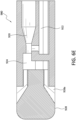
- the Venturi-agitating tip assembly 380 employs a Venturi arrangement with a mixing chamber 324.
- the Venturi-agitating tip assembly 380 has a proximal first end 380a and a distal second end 380b.
- the Venturi-agitating tip assembly 380 includes a hollow cylindrical elongated body 310 having a proximal first end 312, which coincides with the proximal first end 380a of the Venturi-agitating tip assembly 380, and a distal second end 314.
- the proximal first end 380a of the Venturi-agitating tip assembly 380 includes a multi-channel arrangement 381 including first and second inputs 316, 318 for attachment to the dual lumen catheter 360.
- the first and second inputs 316, 318 respectively lead to a first channel 320 and a second channel 322 of the multi-channel arrangement 381 of the Venturi-agitating tip assembly 380.
- the first and second channels 320, 322 lead to, and are in fluid communication with, a mixing chamber 324 (which also forms part of the multi-channel arrangement 381) located in the central portion 326 of the Venturi-agitating tip assembly 380, that is, between the proximal first end 380a and the distal second end 380b.
- a spray tip 328 Located at the distal second end 380b of the Venturi-agitating tip assembly 380, and secured to the distal second end 314 of the elongated body 310, is a spray tip 328 directing the enriched medical suspension in a spray pattern onto the inner lumen of a vessel.
- the first channel 320 and the second channel 322 are interconnected in a manner creating a Venturi effect causing the pressurized chemical solution to effectively pull the medical solution through the second channel 322 and into the mixing chamber 324.
- This is achieved by providing with the first channel 320 with a reduced diameter as it extends from the proximal first end 312 of the elongated body 310 (that is, the first end 320a of the first channel 320) to the central portion 326 of the Venturi-agitating tip assembly 380 (that is, the second end 320b of the first channel 320).
- the diameter of the first channel 320 decreases from a diameter of 0.038 inches adjacent the proximal first end 312 of the elongated body 310 to a diameter of 0.017 inches adjacent the mixing chamber 324.
- the second channel 322 is in fluid communication with the first channel 320. This is achieved by the provisional of a transverse channel 330 connecting the second end 320b of the first channel 320 with the second end 322b of the second channel 322.
- the second channel 322 includes a first end 322a adjacent the proximal first end 312 of the elongated body 310 and a second end 322b adjacent the mixing chamber 324 (although not directly in fluid communication with the mixing chamber 324) and the transverse channel 330.
- the diameter of the second channel 322 is 0.031 inches and remains consistent as it extends from the first end 322a thereof to the second end 322b thereof.
- the first lumen 372 of the dual lumen catheter 360 supplies the pressurized chemical solution and the second lumen 374 supplies the medical solution.
- the first lumen 372 is connected to, and in fluid communication with, the first channel 320 of the Venturi-agitating tip assembly 380 and the second lumen 374 is connected to, and in fluid communication with, the second channel 322 of the Venturi-agitating tip assembly 380.
- the medical solution from the syringe 290 travels through the second lumen 374 of the dual lumen catheter 360 and into the second channel 322 when pressurized chemical solution enters the first channel 320 and passes the transverse channel 330 as it flows into the mixing chamber 324 after being actuated and released from the compressed medical fluid unit 1.
- the pressurized chemical solution entering, and passing through, the Venturi-agitating tip assembly 380 imparts negative pressure on the medical solution in the syringe 290 and draws the medical solution from the syringe 290 through the second channel 322, through the second lumen 374 of the dual lumen catheter 360, through the transverse channel 330, and into the mixing chamber 324 due to the Venturi effect.
- the medical solution and the pressurized chemical solution are then mixed within the mixing chamber 324 to form an enriched medical suspension.
- the syringe plunger 290p is used to regulate or stop flow of medical solution of chemical solution from the syringe 290.
- the pressurized chemical solution and medical solution mixing in the mixing chamber 324 are then forced through the spray tip 328 from which the enriched medical suspension is sprayed upon the inner lumen of a vessel.
- the spray tip 328 includes a plurality of outlets 328a oriented at an angle of 25 degrees to 65 degrees, preferably 45 degrees, relative to the central longitudinal axis of the Venturi-agitating tip assembly 380.
- the force of the pressurized chemical solution traveling through the Venturi-agitating tip assembly 380 and exiting through the spray tip 328 as part of an enriched medical suspension projects the enriched medical suspension from the distal second end 384 of the Venturi-agitating tip assembly 380 as a spray and onto the inner lumen of a vessel.
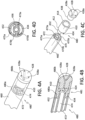
- a Venturi-agitating tip assembly 480 employs a spray tip 428 in conjunction with a multi-channel arrangement 481 where the pressurized chemical solution and medical solution are mixed and forced through the spray tip 428.
- the Venturi-agitating tip assembly 480 includes a proximal first end 480a and a distal second end 480b.
- the Venturi-agitating tip assembly 480 includes a hollow cylindrical elongated body 410 having a proximal first end 412, which coincides with the proximal first end 480a of the Venturi-agitating tip assembly 480, and a distal second end 414.
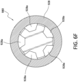
- the Venturi-agitating tip assembly 480 is adapted for use with a dual lumen catheter 460, in particular a dual lumen catheter having concentric lumens, wherein the outer first lumen 472 is annular shaped for the passage of pressurized chemical solution (and has an outer diameter of 0.092 inches at the outer wall thereof and an inner diameter of 0.042 inches at the inner wall thereof) and the inner second lumen 474 is circular shaped for the passage of the medical solution (and has a diameter of 0.030 inches).
- the inner second lumen 474 is supported within the outer first lumen 472 by first and second radially extending rib members 473a, 473b (each having a thickness of 0.006 inches) that extend from the outer surface of the second lumen 474 to the inner surface of the outer first lumen 472. In this way the outer first lumen 472 is divided into first and second semicircular passageways 475a, 475b.
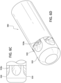
- the proximal first end 480a of the Venturi-agitating tip assembly 480 is formed with two projections 432, 434 shaped and dimensioned for engagement within the outer first lumen 472 of the catheter 460 in a manner blocking a substantial portion of the outer first lumen 472.
- the two projections 432, 434 are arcuate members shaped and dimensioned to respectively block substantial portions of the first and second semicircular passageways 475a, 475b while creating four small passageways 436, each of approximately 0.031 inches (along the Y-axis as shown in Figure 4D ) by 0.050 inches (along the X-axis as shown in figure 4D ) for the passage of pressurized chemical solution therethrough.
- the four small passageways 436 are defined by spaces existing between the edges of the arcuate members 432, 434 and the first and second radially extending rib members 473a, 473b.
- the remainder of the Venturi-agitating tip assembly 480 includes a central mixing chamber 424 that is in fluid communication with the second lumen 474 and the four small passageways 436 feeding pressurized chemical solution from the first lumen 472.
- a spray tip 428 Secured to, and closing off, the second end 414 of the elongated body 410 is a spray tip 428, which is thereby at the distal second end 480b of the Venturi-agitating tip assembly 480.
- Attachment of the spray tip 428 to the elongated body 410 is achieved by providing the spray tip 428 with a projection 438 that seats within the opening at the second end 414 of the elongated body 410.
- the first lumen 472 and the second lumen 474 are interconnected in a manner causing the pressurized chemical solution to effectively pull the medical solution through the second lumen 474 and into the mixing chamber 424.
- the medical solution from the syringe 290 travels through the second lumen 474 of the dual lumen catheter 460 and into the mixing chamber 424 when pressurized chemical solution passes through the four small passageways 436 and enters the mixing chamber 424 (where the medical solution from the syringe 290 and the pressurized chemical solution mix to form an enriched medical suspension) after being actuated and released from compressed medical fluid unit 1.
- the pressurized chemical solution entering, and passing through, the mixing chamber 424 imparts negative pressure on the medical solution in syringe 290 and draws the medical solution from the syringe 290 through the second lumen 474 and into the mixing chamber 424.
- the syringe plunger 290p is used to regulate or stop flow of the medical solution from the syringe 290.
- the pressurized chemical solution and medical solution mixing in the mixing chamber 424 are then forced through the spray tip 428 from which an enriched medical suspension is sprayed upon the inner surface of a lumen.
- the spray tip 428 includes a plurality of outlets 428a oriented at an angle of 25 degrees to 65 degrees, preferably 45 degrees, relative to the central longitudinal axis of the Venturi-agitating tip assembly 480.
- the force of the pressurized chemical solution traveling through the Venturi-agitating tip assembly 480 and exiting through the spray tip 428 as part of an enriched medical suspension projects the enriched medical suspension from the distal second end 484 of the Venturi-agitating tip assembly 480 as a spray and onto the inner lumen of a vessel.
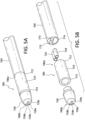
- a Venturi-agitating tip assembly 780 employs a tip 728 in conjunction with a multi-channel arrangement 781 where the pressurized chemical solution and medical solution are mixed to form an enriched medical suspension and forced through the tip 728.
- the Venturi-agitating tip assembly 780 includes proximal first end 780a and a distal second end 780b.
- the Venturi-agitating tip assembly 780 includes a hollow cylindrical elongated body 710 having a proximal first end 712, which coincides with the proximal first end 780a of the Venturi-agitating tip assembly 780, and a distal second end 714.
- the Venturi-agitating tip assembly 780 is adapted for use with a multi-lumen catheter 760, in particular a triple lumen catheter having parallel lumens, wherein the first and second lumens 772, 773 are circular shaped (each with a diameter of 0.039 inches) and are dimensioned for the passage of pressurized chemical solution and the third lumen 774 is semi-circular shaped (with a radius of 0.047 inches) and is dimensioned for the passage of the medical solution.
- the proximal first end 712 of the elongated body 710 at the proximal first end 780a of the Venturi-agitating tip assembly 780 includes first, second and third inputs 716, 717, 718 for attachment to the multi-lumen catheter 760.
- the first and second inputs 716, 717 lead to a first channel 720 and the third input 718 to a second channel 722.
- the proximal first end 712 of the elongated body 710 at the proximal first end 780a of the Venturi-agitating tip assembly 780 is formed with two circular tubular projections 732, 734, defining the first and second inputs 716, 717.
- the circular tubular projections 732, 734 (each with an inner diameter of 0.027 inches and an outer diameter of 0.039 inches) are shaped and dimensioned for engagement within the first and second lumens 772, 773 of the catheter 760 in a manner allowing for the flow of fluid from the first and second lumens 772, 773 and into the Venturi-agitating tip assembly 780.
- the two circular tubular projections 732, 734 are shaped and dimensioned to fit within the first and second lumens 772, 773 while maintaining passageways for the passage of pressurized chemical solution therethrough.
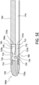
- the first and second channels 720, 722 lead to, and are in fluid communication with, a mixing chamber 724 located in the central portion 726 of the Venturi-agitating tip assembly 780, that is, between the proximal first end 712 and the distal second end 714 of the elongated body.
- a tip 728 Secured to the distal second end 714 of the elongated body 710, and positioned at the distal second end 780b of the Venturi-agitating tip assembly, is a tip 728 having three outlets 728a, 728b, 728c extending from the mixing chamber 724 to the exterior at the distal end of the Venturi-agitating tip assembly 780 at an angle of 25 degrees to 65 degrees, preferably 45 degrees, relative to the central longitudinal axis of the Venturi-agitating tip assembly 780.
- the first channel 720 and the second channel 722 are interconnected in a manner creating a Venturi effect causing the pressurized chemical solution to effectively pull the medical solution through the second channel 722 and into the mixing chamber 724.
- This is achieved by providing the first channel 720 with a reduced diameter (decreasing from 0.038 inches to 0.017 inches) as it extends from the proximal first end 712 of the elongated body 710 (that is, the first end 720a of the first channel 720) to the central portion 726 of the Venturi-agitating tip assembly 780 (that is, the second end 720b of the first channel 720).
- the diameter of the first channel 720 decreases from a diameter of 0.038 inches adjacent the proximal first end 712 of the elongated body 710 to a diameter of 0.017 inches adjacent the mixing chamber 724.
- the second channel 722 is in fluid communication with the first channel 720. This is achieved by the provisional of a transverse channel 730 connecting the second end 720b of the first channel 720 with the second end 722b of the second channel 722.
- the second channel 722 includes a first end 722a adjacent the proximal first end 712 of the elongated body 710 and a second end 722b adjacent the mixing chamber 724 (although not directly in fluid communication with the mixing chamber 724) and the transverse channel 730.
- the diameter of the second channel 722 is 0.047 inches and remains consistent as it extends from the first end 722a thereof to the second end 722b thereof.
- the first and second lumens 772, 773 supply the pressurized chemical solution and the third lumen 774 supplies the medical solution.
- the first and second lumens 772, 773 are connected to, and in fluid communication with, the first channel 720 of the Venturi-agitating tip assembly 780.
- the third lumen 774 is connected to, and in fluid communication with, the second channel 722 of the Venturi-agitating tip assembly 780.
- the medical solution from syringe 290 travels through third lumen 774 of multi-lumen lumen catheter 760 and into the second channel 722 when pressurized chemical solution enters the first channel 720 and passes the transverse channel 730 (having a size of 0.020 inches) into the mixing chamber 724 after being actuated and released from compressed medical fluid unit 1.
- the pressurized chemical solution entering, and passing through, the Venturi-agitating tip assembly 780 imparts negative pressure on the medical solution in syringe 290 and draws the medical solution from the syringe 290 through second channel 722, through the third lumen 774 of the dual lumen catheter 760, and into the mixing chamber 724 due to the Venturi effect.
- the syringe plunger 290p is used to regulate or stop flow of medical solution from the syringe 290.
- the pressurized chemical solution and medical solution mixing in the mixing chamber 724 form an enriched medical suspension that is then forced through the outlets 728a-c of the spray tip 728.
- the force of the pressurized medical chemical solution traveling through the Venturi-agitating tip assembly 780 and exiting through the spray tip 728 as part of an enriched medical suspension projects the enriched medical suspension from the distal second end 784 of the Venturi-agitating tip assembly 780 as a spray and onto the inner lumen of a vessel.
- outlets of the spray tip in the embodiments disclosed above with reference to Figures 3A-C , Figures 4A-D , and 5A-E are positioned along a forward portion of the spray tip, it is appreciated the outlets of the spray tip could be positioned along the outer circumferential wall of the spray tip as shown in Figure 2 .
- the outlets of the spray tip could be positioned along the outer circumferential wall of the spray tip as shown in Figure 2 .
- the enriched medical suspension is sprayed from the Venturi-agitating tip assembly onto the inner lumen of a vessel.
- Those portions of the Venturi-agitating tip assembly 920 proximal to the spray tip 928, for example, the mixing chamber 924, the first channel 920, and the second channel 922 are the same as found in the embodiment disclosed with reference to Figures 3A-3C .
- the spray tip 928 includes a plurality of circumferentially oriented outlets 928a positioned so as to dispense the enriched medical suspension through the outer circumferential wall 929 of the spray tip 928.
- the enriched medical suspension exiting the Venturi-agitating tip assembly is directed to a vessel requiring treatment.
- a method for treatment in accordance with the present invention is achieved in the following manner.
- the first end of the suspension delivery catheter, that is, Venturi-agitating tip assembly is introduced into a diseased/varicosed vein requiring treatment such that the first end of Venturi-agitating tip assembly is positioned beyond the section of vein requiring treatment.
- the second end of the delivery catheter is coupled to the compressed medical fluid unit and the syringe.
- the compressed medical fluid unit is actuated to supply pressurized chemical solution to the suspension delivery catheter and an enriched medical suspension is produced at the Venturi-agitating tip assembly of the suspension delivery catheter.
- the enriched medical suspension sprays from the first end of Venturi-agitating tip assembly into the section of vein requiring treatment.
- the enriched medical suspension includes a sclerosant for the destruction of a diseased vein
- the enriched medical suspension is sprayed into the vein at various segments causing the vein to go into spasm resulting in eventual destruction of the diseased vein.
- the apparatus of the present invention is used in the treatment of the arterial or venous system without the goal of spasm or vessel destruction, the enriched medical suspension is sprayed, or otherwise delivered, as required for the procedure being performed.
- this procedure can be performed under ultrasound guidance or radiograph in order for the physician to control the amount of liquid to mix with the pressurized chemical solution to form the enriched medical suspension.
- the present suspension delivery catheter may be used in the treatment of various vascular ailments.
- the potential treatments that may employ the present suspension delivery catheter include, but are not limited to the following, oncology medical solutions, microbeads, magnetic beads or particles for thrombus treatment, metallic beads or particles for thrombus treatment, embolics, driving drugs through the blood-brain barrier for neurological conditions, driving or delivering TPA (Tissue Plasminogen Activator) for thrombolytic usage, etc.
- TPA tissue Plasminogen Activator
- microparticles are used in conjunction with the enriched medical suspension composed of the chemical and medical solutions, saline may be used with the microparticles, so as to place the microparticles into suspension.
Landscapes
- Health & Medical Sciences (AREA)
- Life Sciences & Earth Sciences (AREA)
- Heart & Thoracic Surgery (AREA)
- Animal Behavior & Ethology (AREA)
- Public Health (AREA)
- Biomedical Technology (AREA)
- Hematology (AREA)
- Engineering & Computer Science (AREA)
- Veterinary Medicine (AREA)
- General Health & Medical Sciences (AREA)
- Anesthesiology (AREA)
- Pulmonology (AREA)
- Biophysics (AREA)
- Infusion, Injection, And Reservoir Apparatuses (AREA)
- Media Introduction/Drainage Providing Device (AREA)
- Medical Preparation Storing Or Oral Administration Devices (AREA)
- Materials For Medical Uses (AREA)
Claims (8)
- Vorrichtung zur Erzeugung einer medizinischen Fluidsuspension, umfassend:eine Venturi-Rührspitzen-Baugruppe (380, 480, 780), aufweisend ein proximales erstes Ende (380a, 480a, 780a), ein distales zweites Ende (380b, 480b, 780b) und einen mittleren Abschnitt (326, 726) zwischen dem proximalen ersten Ende (380a, 480a, 780a) und dem distalen zweiten Ende (380b, 480b, 780b), wobei die Venturi-Rührspitzen-Baugruppe (380, 480, 780) auch eine Mehrkanalanordnung (381, 481, 781) mit ersten und zweiten Eingängen (316, 318, 416, 418, 716, 718) zum Anlegen an einen Dual-Lumen-Katheter (360, 460, 760) aufweist, wobei die ersten und zweiten Eingänge (316, 318, 416, 418, 716, 718) jeweils zu einem ersten Kanal (320, 720), zu einem zweiten Kanal (322, 730) und zu einer in dem mittleren Abschnitt (326, 426, 726) der Venturi-Rührspitzen-Baugruppe (380, 480, 780) angeordneten Mischkammer (324, 424, 724) führen, wobei die ersten und zweiten Kanäle (320, 322, 420, 422, 720, 722) zu der Mischkammer (324) führen und mit dieser in einer Fluidkommunikation stehen, und alle derart miteinander verbunden sind, dass ein Venturi-Effekt erzeugt wird, wobei die Venturi-Rührspitzen-Baugruppe (380, 480, 780) ferner eine Sprühspitze (328, 428, 728) an dem distalen zweiten Ende (380b, 480b, 780b) der Venturi-Rührspitzen-Baugruppe (380, 480, 780) aufweist, wobei die Sprühspitze (328, 428, 728) Auslässe (328a, 428a, 728a) aufweist, die derart orientiert sind, dass eine angereicherte medizinische Suspension unter einem Winkel von 25 Grad bis 65 Grad relativ zu einer Längsachse der Venturi-Rührspitzen-Baugruppe (380, 480, 780) gesprüht wird;eine Quelle einer unter Druck stehenden chemischen Lösung (18) mit einer kompressiblen Spritze (12) enthaltend eine chemische Lösung (18), um diese von einem Auslass (20) der Spritze (12) abzugeben, wobei die Spritze (12) ein Einwegventil (22) an ihrem Auslass (20) enthält, um zu gewährleisten, dass die unter Druck stehende chemische Lösung (18) von der Spritze (12) nur aus der Spritze (12) herausfließt;eine Quelle einer medizinischen Lösung (19); undeinen Dual-Lumen-Katheter (360, 460, 760), der die Venturi-Rührspitzen-Baugruppe (380, 480, 780) mit der Quelle der unter Druck stehenden chemischen Lösung (18) und mit der Quelle einer medizinischen Lösung (19) verbindet;wobei der erste Kanal (320, 720) und der zweite Kanal (322, 730) derart miteinander verbunden sind, dass der Venturi-Effekt in der Venturi-Rührspitzen-Baugruppe (380, 480, 780) erzeugt wird, um zu verursachen, dass die unter Druck stehende chemische Lösung (18) wirksam die medizinische Lösung (19) durch den zweiten Kanal (322) und in die Mischkammer (324) zieht, in der die unter Druck stehende chemische Lösung (18) und die medizinische Lösung (19) die angereicherte medizinische Suspension bilden.
- Vorrichtung nach Anspruch 1, wobei die Quelle der unter Druck stehenden chemischen Lösung (18) eine komprimierte medizinische Fluideinheit (1) enthält.
- Vorrichtung nach Anspruch 1 oder 2, wobei die Quelle der medizinischen Lösung (19) eine weitere Spritze (290) enthält.
- Vorrichtung nach Anspruch 3, wobei ein Mikroschlauch die Quelle der unter Druck stehenden chemischen Lösung (18) mit einem ersten Lumen (272, 372, 472) des Dual-Lumen-Katheters (360, 460, 760) verbindet.
- Vorrichtung nach Anspruch 4, wobei die Quelle der medizinischen Lösung (19) mit dem zweiten Lumen (274, 374, 474) des Dual-Lumen-Katheters (360, 460, 760) verbunden ist.
- Vorrichtung nach Anspruch 3, wobei die weitere Spritze (290) ein Einwegventil (291) enthält.
- Vorrichtung nach Anspruch 1, wobei ein Mikroschlauch die Quelle der unter Druck stehenden chemischen Lösung (18) mit einem ersten Lumen (272, 372, 472) des Dual-Lumen-Katheters (360, 460, 760) verbindet.
- Vorrichtung nach Anspruch 7, wobei die Quelle der medizinischen Lösung (19) mit dem zweiten Lumen (274, 374, 474) verbunden ist.
Applications Claiming Priority (2)
| Application Number | Priority Date | Filing Date | Title |
|---|---|---|---|
| US201862653635P | 2018-04-06 | 2018-04-06 | |
| PCT/US2019/026066 WO2019195730A1 (en) | 2018-04-06 | 2019-04-05 | Apparatus and method for producing an enriched medical suspension |
Publications (4)
| Publication Number | Publication Date |
|---|---|
| EP3758772A1 EP3758772A1 (de) | 2021-01-06 |
| EP3758772A4 EP3758772A4 (de) | 2021-12-15 |
| EP3758772B1 true EP3758772B1 (de) | 2024-10-09 |
| EP3758772C0 EP3758772C0 (de) | 2024-10-09 |
Family
ID=68099240
Family Applications (1)
| Application Number | Title | Priority Date | Filing Date |
|---|---|---|---|
| EP19782069.9A Active EP3758772B1 (de) | 2018-04-06 | 2019-04-05 | Vorrichtung zur herstellung einer angereicherten medizinischen suspension |
Country Status (8)
| Country | Link |
|---|---|
| US (3) | US11185643B2 (de) |
| EP (1) | EP3758772B1 (de) |
| JP (1) | JP7165808B2 (de) |
| CN (1) | CN112203704A (de) |
| AU (1) | AU2019247867B2 (de) |
| CA (1) | CA3095939C (de) |
| MX (1) | MX2020010500A (de) |
| WO (1) | WO2019195730A1 (de) |
Families Citing this family (3)
| Publication number | Priority date | Publication date | Assignee | Title |
|---|---|---|---|---|
| US20190070397A1 (en) * | 2006-11-27 | 2019-03-07 | Frank Levy | Apparatus and method for producing co2 enriched medical foam |
| DE102018121513B4 (de) * | 2018-09-04 | 2020-04-02 | Prof. Reymond & Hetzel GbR (vertretungsberechtigter Gesellschafter: Alexander Hetzel, 78667 Villingendorf) | Medizinisches Instrument zum gerichteten Einbringen einer Substanz in einen Hohlraum eines Körpers und Werkzeug dafür |
| US12409271B2 (en) * | 2022-04-25 | 2025-09-09 | Frank Levy | Apparatus and method for producing an enriched medical suspension |
Family Cites Families (59)
| Publication number | Priority date | Publication date | Assignee | Title |
|---|---|---|---|---|
| DE434372C (de) * | 1926-09-24 | Klemens Bergl Dr | Hygienischer Spuelapparat | |
| GB455965A (en) * | 1935-04-27 | 1936-10-27 | Hans Herbert Schulz | Improvements in and relating to pumps, syringes, and like appliances for surgical and other purposes |
| US2475511A (en) | 1942-03-26 | 1949-07-05 | Raymond T Moloney | Beverage dispensing system |
| US2828889A (en) | 1954-11-01 | 1958-04-01 | Practical Products Company | Beverage vending machine |
| US3831844A (en) | 1972-02-17 | 1974-08-27 | J Tropeano | Apparatus for snow making |
| EP0175760A1 (de) * | 1984-03-19 | 1986-04-02 | FOURNIER, Erick-Pierre | Rektaldusche zur prophylaktischen anwendung |
| US5580530A (en) | 1987-07-30 | 1996-12-03 | Johnson & Johnson Medical, Inc. | Device for vapor sterilization of articles having lumens |
| US4842591A (en) * | 1988-01-21 | 1989-06-27 | Luther Ronald B | Connector with one-way septum valve, and assembly |
| US5246140A (en) | 1988-06-23 | 1993-09-21 | Micro Matic A/S | Container device for distributing a drinkable liquid under pressure from a gas |
| DE3911054C3 (de) | 1989-04-05 | 1997-01-02 | Wagner Foerdertechnik | Navigationssystem und -Verfahren zur leitdrahtlosen Führung von fahrerlosen Flurförderzeugen |
| CA2034285A1 (en) | 1990-02-09 | 1991-08-10 | Masao Yafuso | Method and system for monitoring of blood constituents in vivo |
| DE69230613T2 (de) | 1991-07-02 | 2000-12-28 | Inhale Inc | Verfahren und vorrichtung zum abgeben von medikamenten in aerosolform |
| US5395318A (en) | 1994-01-24 | 1995-03-07 | Kaprelian; Edward K. | Method and apparatus for wound treatment |
| ZA954936B (en) * | 1994-06-17 | 1996-02-27 | Trudell Medical Ltd | Nebulizing catheter system and methods of use and manufacture |
| US5840026A (en) * | 1994-09-21 | 1998-11-24 | Medrad, Inc. | Patient specific dosing contrast delivery systems and methods |
| US5699961A (en) | 1995-05-05 | 1997-12-23 | Ratnik Industries, Inc. | Fanless snow gun |
| US5875776A (en) | 1996-04-09 | 1999-03-02 | Vivorx Pharmaceuticals, Inc. | Dry powder inhaler |
| GB9700571D0 (en) | 1997-01-13 | 1997-03-05 | Knight Brian G | Agricultural crop spraying apparatus |
| US6068861A (en) | 1998-06-01 | 2000-05-30 | Albemarle Corporation | Concentrated aqueous bromine solutions and their preparation |
| US6317623B1 (en) | 1999-03-12 | 2001-11-13 | Medrad, Inc. | Apparatus and method for controlling contrast enhanced imaging procedures |
| GB9912356D0 (en) | 1999-05-26 | 1999-07-28 | Btg Int Ltd | Generation of microfoam |
| US6402047B1 (en) | 1999-10-29 | 2002-06-11 | Kevin S. Thomas | Snow making apparatus and method |
| JP4441025B2 (ja) * | 1999-12-15 | 2010-03-31 | Hoya株式会社 | 内視鏡用噴霧具 |
| TW548090B (en) * | 2000-03-14 | 2003-08-21 | Sankyo Rayjac Co Ltd | Nozzle and aspirator with nozzle |
| US7632241B2 (en) * | 2000-05-19 | 2009-12-15 | Conmed Endoscopic Technologies, Inc. | Multi-lumen biliary catheter with angled guidewire exit |
| US6474091B2 (en) | 2000-09-18 | 2002-11-05 | Francisco Javier Guerra | Illusionary snow apparatus |
| GB0028692D0 (en) | 2000-11-24 | 2001-01-10 | Btg Int Ltd | Generation of therapeutic microform |
| DE20020252U1 (de) * | 2000-11-29 | 2002-04-11 | Maslanka, Herbert, 78532 Tuttlingen | Sprühkatheter |
| KR100873497B1 (ko) | 2002-10-17 | 2008-12-15 | 삼성전자주식회사 | 지문 인식 소자를 내장한 일체형 액정표시장치 및 이의제조 방법 |
| AU2004290957A1 (en) | 2003-11-17 | 2005-06-02 | Btg International Limited | Methods of preparing a foam comprising a sclerosing agent |
| JP2006003797A (ja) | 2004-06-21 | 2006-01-05 | Toyota Industries Corp | 照明装置及び照明方法 |
| TWI260427B (en) | 2004-07-09 | 2006-08-21 | Hon Hai Prec Ind Co Ltd | Grating spectrograph |
| US20070078739A1 (en) | 2005-10-03 | 2007-04-05 | Levin Robert A | Commodities based securities and shipping certificate therefor |
| US7543760B2 (en) | 2006-11-27 | 2009-06-09 | Frank Levy | Portable evaporative snow apparatus |
| US8876749B2 (en) | 2006-11-27 | 2014-11-04 | Frank Levy | Apparatus and process for producing CO2 enriched medical foam |
| WO2007114934A2 (en) | 2006-04-04 | 2007-10-11 | Vnus Medical Technologies, Inc. | Method and apparatus for generating vascular treatment foam |
| US20080012099A1 (en) | 2006-07-11 | 2008-01-17 | Shing Yeh | Electronic assembly and manufacturing method having a reduced need for wire bonds |
| US20080016762A1 (en) | 2006-07-20 | 2008-01-24 | Bradley Emalfarb | Wire foliage container with rigid support |
| US10149935B2 (en) | 2006-11-27 | 2018-12-11 | Frank Levy | Delivery system and method for the effective and reliable delivery of controlled amounts of a medical fluid |
| US10322271B2 (en) | 2006-11-27 | 2019-06-18 | Frank Levy | Delivery system and method for the effective and reliable delivery of controlled amounts of a medical fluid |
| US20190070397A1 (en) | 2006-11-27 | 2019-03-07 | Frank Levy | Apparatus and method for producing co2 enriched medical foam |
| US10155093B2 (en) | 2006-11-27 | 2018-12-18 | Frank Levy | Apparatus and method for producing CO2 enriched medical foam |
| US10350399B2 (en) * | 2006-11-27 | 2019-07-16 | Frank Levy | Apparatus and method for producing an enriched medical suspension of carbon dioxide |
| KR101435235B1 (ko) | 2006-12-27 | 2014-08-28 | 카오카부시키가이샤 | 용기에 담은 음료 |
| US20090031889A1 (en) | 2007-05-18 | 2009-02-05 | Saul W Venner | Complex Geometry Composite Armor for Military Applications |
| JP2008295849A (ja) * | 2007-06-01 | 2008-12-11 | Aska Pharmaceutical Co Ltd | スプレー容器 |
| US8496629B2 (en) * | 2008-04-22 | 2013-07-30 | Becton, Dickinson And Company | Catheter hole having a flow breaking feature |
| EP2282984B1 (de) | 2008-05-01 | 2012-11-21 | Exxonmobil Chemical Patents Inc. | Verfahren zur herstellung von cyclohexylbenzol |
| US8210453B2 (en) * | 2008-09-12 | 2012-07-03 | Confluent Surgical, Inc. | Spray applicator |
| CA2781313C (en) * | 2009-12-23 | 2019-09-17 | Map Pharmaceuticals, Inc. | Enhanced eductor design |
| WO2012009187A1 (en) * | 2010-07-15 | 2012-01-19 | Becton, Dickinson And Company | A catheter hole having an inclined trailing edge |
| US20120030566A1 (en) | 2010-07-28 | 2012-02-02 | Victor B Michael | System with touch-based selection of data items |
| EP2548606A1 (de) | 2011-07-20 | 2013-01-23 | Florian Netzer | Katheter zur Erzeugung eines räumlich getrennten Gefäßabschnitts |
| EP2604209B1 (de) * | 2011-12-13 | 2017-08-02 | VascoMed GmbH | Spülkathetereinrichtung und Ablationsanordnung |
| US9884147B2 (en) * | 2012-01-13 | 2018-02-06 | Kemi Azeez | Device and method for cleaning nasal cavities |
| US10034986B2 (en) * | 2013-11-11 | 2018-07-31 | Crossbay Medical, Inc. | Method and apparatus of tubal patency catheter and delivery systems |
| WO2015149921A1 (en) * | 2014-03-31 | 2015-10-08 | Boehringer Ingelheim Vetmedica Gmbh | Inhaler |
| WO2016139606A1 (en) * | 2015-03-02 | 2016-09-09 | Accurate Medical Therapeutics Ltd. | Preventing non-target embolization |
| US20170153165A1 (en) | 2015-11-30 | 2017-06-01 | Chidozie O. Nwadigo | Syringe assembly for withdrawing two separate portions of fluid following a single engagement with fluid port |
-
2019
- 2019-04-05 MX MX2020010500A patent/MX2020010500A/es unknown
- 2019-04-05 JP JP2021504133A patent/JP7165808B2/ja active Active
- 2019-04-05 WO PCT/US2019/026066 patent/WO2019195730A1/en not_active Ceased
- 2019-04-05 EP EP19782069.9A patent/EP3758772B1/de active Active
- 2019-04-05 CN CN201980034980.8A patent/CN112203704A/zh active Pending
- 2019-04-05 US US16/376,841 patent/US11185643B2/en active Active
- 2019-04-05 AU AU2019247867A patent/AU2019247867B2/en active Active
- 2019-04-05 CA CA3095939A patent/CA3095939C/en active Active
-
2021
- 2021-11-02 US US17/453,296 patent/US12171933B2/en active Active
-
2024
- 2024-10-25 US US18/926,995 patent/US20250041541A1/en active Pending
Also Published As
| Publication number | Publication date |
|---|---|
| EP3758772A4 (de) | 2021-12-15 |
| US20250041541A1 (en) | 2025-02-06 |
| AU2019247867A1 (en) | 2020-10-22 |
| AU2019247867B2 (en) | 2024-06-27 |
| CA3095939A1 (en) | 2019-10-10 |
| EP3758772A1 (de) | 2021-01-06 |
| US12171933B2 (en) | 2024-12-24 |
| US20220054770A1 (en) | 2022-02-24 |
| CN112203704A (zh) | 2021-01-08 |
| CA3095939C (en) | 2023-09-26 |
| EP3758772C0 (de) | 2024-10-09 |
| US11185643B2 (en) | 2021-11-30 |
| MX2020010500A (es) | 2020-11-12 |
| WO2019195730A1 (en) | 2019-10-10 |
| JP2021520965A (ja) | 2021-08-26 |
| US20190307971A1 (en) | 2019-10-10 |
| JP7165808B2 (ja) | 2022-11-04 |
Similar Documents
| Publication | Publication Date | Title |
|---|---|---|
| US20250041541A1 (en) | Apparatus and method for producing an enriched medical suspension | |
| US11690988B2 (en) | Apparatus and method for producing an enriched medical suspension | |
| US8657777B2 (en) | Rapid exchange fluid jet catheter | |
| JP6433964B2 (ja) | 鼻治療のための噴霧器 | |
| CN103282069B (zh) | 小型流体雾化器 | |
| US11679244B2 (en) | Apparatus and method for producing an enriched medical suspension of carbon dioxide | |
| US20250367364A1 (en) | Apparatus and method for producing an enriched medical contrast suspension | |
| CN218739765U (zh) | 便于装配的雾化导管 | |
| US12409271B2 (en) | Apparatus and method for producing an enriched medical suspension | |
| JP2016043265A (ja) | 混合流体を吐出するアプリケーター、ミキシングチップ、及び方法 | |
| HK40044451A (en) | Apparatus and method for producing an enriched medical suspension | |
| CN222056050U (zh) | 导流头、导流组件以及喷洒管 | |
| CN105194771A (zh) | 小型流体雾化器 | |
| US20230285728A1 (en) | Apparatus and method for producing an enriched medical suspension | |
| US12377251B2 (en) | Apparatus and method for producing an enriched medical suspension of carbon dioxide | |
| KR20250158237A (ko) | 5mm 또는 10mm 이류체 노즐 돔형 캡 |
Legal Events
| Date | Code | Title | Description |
|---|---|---|---|
| STAA | Information on the status of an ep patent application or granted ep patent |
Free format text: STATUS: THE INTERNATIONAL PUBLICATION HAS BEEN MADE |
|
| PUAI | Public reference made under article 153(3) epc to a published international application that has entered the european phase |
Free format text: ORIGINAL CODE: 0009012 |
|
| STAA | Information on the status of an ep patent application or granted ep patent |
Free format text: STATUS: REQUEST FOR EXAMINATION WAS MADE |
|
| 17P | Request for examination filed |
Effective date: 20200930 |
|
| AK | Designated contracting states |
Kind code of ref document: A1 Designated state(s): AL AT BE BG CH CY CZ DE DK EE ES FI FR GB GR HR HU IE IS IT LI LT LU LV MC MK MT NL NO PL PT RO RS SE SI SK SM TR |
|
| AX | Request for extension of the european patent |
Extension state: BA ME |
|
| DAV | Request for validation of the european patent (deleted) | ||
| DAX | Request for extension of the european patent (deleted) | ||
| A4 | Supplementary search report drawn up and despatched |
Effective date: 20211116 |
|
| RIC1 | Information provided on ipc code assigned before grant |
Ipc: A61M 39/22 20060101ALI20211110BHEP Ipc: A61M 5/19 20060101ALI20211110BHEP Ipc: A61J 1/22 20060101ALI20211110BHEP Ipc: A61J 1/20 20060101ALI20211110BHEP Ipc: A61B 8/08 20060101ALI20211110BHEP Ipc: A61M 5/00 20060101AFI20211110BHEP |
|
| STAA | Information on the status of an ep patent application or granted ep patent |
Free format text: STATUS: EXAMINATION IS IN PROGRESS |
|
| 17Q | First examination report despatched |
Effective date: 20231005 |
|
| GRAP | Despatch of communication of intention to grant a patent |
Free format text: ORIGINAL CODE: EPIDOSNIGR1 |
|
| STAA | Information on the status of an ep patent application or granted ep patent |
Free format text: STATUS: GRANT OF PATENT IS INTENDED |
|
| INTG | Intention to grant announced |
Effective date: 20240426 |
|
| GRAS | Grant fee paid |
Free format text: ORIGINAL CODE: EPIDOSNIGR3 |
|
| GRAA | (expected) grant |
Free format text: ORIGINAL CODE: 0009210 |
|
| STAA | Information on the status of an ep patent application or granted ep patent |
Free format text: STATUS: THE PATENT HAS BEEN GRANTED |
|
| AK | Designated contracting states |
Kind code of ref document: B1 Designated state(s): AL AT BE BG CH CY CZ DE DK EE ES FI FR GB GR HR HU IE IS IT LI LT LU LV MC MK MT NL NO PL PT RO RS SE SI SK SM TR |
|
| REG | Reference to a national code |
Ref country code: CH Ref legal event code: EP |
|
| REG | Reference to a national code |
Ref country code: DE Ref legal event code: R096 Ref document number: 602019060132 Country of ref document: DE |
|
| REG | Reference to a national code |
Ref country code: IE Ref legal event code: FG4D |
|
| U01 | Request for unitary effect filed |
Effective date: 20241016 |
|
| U07 | Unitary effect registered |
Designated state(s): AT BE BG DE DK EE FI FR IT LT LU LV MT NL PT RO SE SI Effective date: 20241104 |
|
| PG25 | Lapsed in a contracting state [announced via postgrant information from national office to epo] |
Ref country code: HR Free format text: LAPSE BECAUSE OF FAILURE TO SUBMIT A TRANSLATION OF THE DESCRIPTION OR TO PAY THE FEE WITHIN THE PRESCRIBED TIME-LIMIT Effective date: 20241009 Ref country code: IS Free format text: LAPSE BECAUSE OF FAILURE TO SUBMIT A TRANSLATION OF THE DESCRIPTION OR TO PAY THE FEE WITHIN THE PRESCRIBED TIME-LIMIT Effective date: 20250209 |
|
| PG25 | Lapsed in a contracting state [announced via postgrant information from national office to epo] |
Ref country code: ES Free format text: LAPSE BECAUSE OF FAILURE TO SUBMIT A TRANSLATION OF THE DESCRIPTION OR TO PAY THE FEE WITHIN THE PRESCRIBED TIME-LIMIT Effective date: 20241009 |
|
| PG25 | Lapsed in a contracting state [announced via postgrant information from national office to epo] |
Ref country code: NO Free format text: LAPSE BECAUSE OF FAILURE TO SUBMIT A TRANSLATION OF THE DESCRIPTION OR TO PAY THE FEE WITHIN THE PRESCRIBED TIME-LIMIT Effective date: 20250109 |
|
| PG25 | Lapsed in a contracting state [announced via postgrant information from national office to epo] |
Ref country code: GR Free format text: LAPSE BECAUSE OF FAILURE TO SUBMIT A TRANSLATION OF THE DESCRIPTION OR TO PAY THE FEE WITHIN THE PRESCRIBED TIME-LIMIT Effective date: 20250110 |
|
| PG25 | Lapsed in a contracting state [announced via postgrant information from national office to epo] |
Ref country code: PL Free format text: LAPSE BECAUSE OF FAILURE TO SUBMIT A TRANSLATION OF THE DESCRIPTION OR TO PAY THE FEE WITHIN THE PRESCRIBED TIME-LIMIT Effective date: 20241009 |
|
| PG25 | Lapsed in a contracting state [announced via postgrant information from national office to epo] |
Ref country code: RS Free format text: LAPSE BECAUSE OF FAILURE TO SUBMIT A TRANSLATION OF THE DESCRIPTION OR TO PAY THE FEE WITHIN THE PRESCRIBED TIME-LIMIT Effective date: 20250109 |
|
| U20 | Renewal fee for the european patent with unitary effect paid |
Year of fee payment: 7 Effective date: 20250428 |
|
| PG25 | Lapsed in a contracting state [announced via postgrant information from national office to epo] |
Ref country code: SM Free format text: LAPSE BECAUSE OF FAILURE TO SUBMIT A TRANSLATION OF THE DESCRIPTION OR TO PAY THE FEE WITHIN THE PRESCRIBED TIME-LIMIT Effective date: 20241009 |
|
| PG25 | Lapsed in a contracting state [announced via postgrant information from national office to epo] |
Ref country code: SK Free format text: LAPSE BECAUSE OF FAILURE TO SUBMIT A TRANSLATION OF THE DESCRIPTION OR TO PAY THE FEE WITHIN THE PRESCRIBED TIME-LIMIT Effective date: 20241009 |
|
| PG25 | Lapsed in a contracting state [announced via postgrant information from national office to epo] |
Ref country code: CZ Free format text: LAPSE BECAUSE OF FAILURE TO SUBMIT A TRANSLATION OF THE DESCRIPTION OR TO PAY THE FEE WITHIN THE PRESCRIBED TIME-LIMIT Effective date: 20241009 |
|
| PLBE | No opposition filed within time limit |
Free format text: ORIGINAL CODE: 0009261 |
|
| STAA | Information on the status of an ep patent application or granted ep patent |
Free format text: STATUS: NO OPPOSITION FILED WITHIN TIME LIMIT |
|
| 26N | No opposition filed |
Effective date: 20250710 |
|
| REG | Reference to a national code |
Ref country code: CH Ref legal event code: H13 Free format text: ST27 STATUS EVENT CODE: U-0-0-H10-H13 (AS PROVIDED BY THE NATIONAL OFFICE) Effective date: 20251125 |
|
| PG25 | Lapsed in a contracting state [announced via postgrant information from national office to epo] |
Ref country code: MC Free format text: LAPSE BECAUSE OF FAILURE TO SUBMIT A TRANSLATION OF THE DESCRIPTION OR TO PAY THE FEE WITHIN THE PRESCRIBED TIME-LIMIT Effective date: 20241009 |
|
| GBPC | Gb: european patent ceased through non-payment of renewal fee |
Effective date: 20250405 |
|
| PG25 | Lapsed in a contracting state [announced via postgrant information from national office to epo] |
Ref country code: GB Free format text: LAPSE BECAUSE OF NON-PAYMENT OF DUE FEES Effective date: 20250405 |
|
| PG25 | Lapsed in a contracting state [announced via postgrant information from national office to epo] |
Ref country code: CH Free format text: LAPSE BECAUSE OF NON-PAYMENT OF DUE FEES Effective date: 20250430 |