EP3758552B1 - Shelf and shelf arrangement - Google Patents
Shelf and shelf arrangement Download PDFInfo
- Publication number
- EP3758552B1 EP3758552B1 EP19710596.8A EP19710596A EP3758552B1 EP 3758552 B1 EP3758552 B1 EP 3758552B1 EP 19710596 A EP19710596 A EP 19710596A EP 3758552 B1 EP3758552 B1 EP 3758552B1
- Authority
- EP
- European Patent Office
- Prior art keywords
- shelf
- linear guide
- support structure
- hook
- lug
- Prior art date
- Legal status (The legal status is an assumption and is not a legal conclusion. Google has not performed a legal analysis and makes no representation as to the accuracy of the status listed.)
- Active
Links
Images
Classifications
-
- A—HUMAN NECESSITIES
- A47—FURNITURE; DOMESTIC ARTICLES OR APPLIANCES; COFFEE MILLS; SPICE MILLS; SUCTION CLEANERS IN GENERAL
- A47B—TABLES; DESKS; OFFICE FURNITURE; CABINETS; DRAWERS; GENERAL DETAILS OF FURNITURE
- A47B96/00—Details of cabinets, racks or shelf units not covered by a single one of groups A47B43/00 - A47B95/00; General details of furniture
- A47B96/02—Shelves
- A47B96/025—Shelves with moving elements, e.g. movable extensions or link elements
-
- A—HUMAN NECESSITIES
- A47—FURNITURE; DOMESTIC ARTICLES OR APPLIANCES; COFFEE MILLS; SPICE MILLS; SUCTION CLEANERS IN GENERAL
- A47B—TABLES; DESKS; OFFICE FURNITURE; CABINETS; DRAWERS; GENERAL DETAILS OF FURNITURE
- A47B57/00—Cabinets, racks or shelf units, characterised by features for adjusting shelves or partitions
- A47B57/04—Cabinets, racks or shelf units, characterised by features for adjusting shelves or partitions with means for adjusting the inclination of the shelves
Definitions
- Shelves are usually an integral part of shelves and are attached to the sides of vertical shelf supports, for example.
- the shelves have a support surface on which goods can be stored and/or displayed.
- the support surface is often arranged at an angle to encourage the goods on it to slide. This principle of the inclined plane is increasingly used in sales shelves.
- the support surface of the shelves is inclined towards the front towards the side where the goods are removed, for example to cause goods units that are usually arranged in a row one behind the other to slide forward automatically when a goods unit at the front has been removed.
- a possible embodiment of such a sliding shelf is shown in the DE 201 14 098 U1 known.
- the shelves are attached to shelf supports by hanging the shelves on the long holes in the shelf supports.
- the shelf supports each have a large number of long holes, which are arranged in a row one behind the other along the length of the shelf supports.
- the support surface of the shelves can be inclined by hanging them in the corresponding long holes in these rows of long holes.
- One object of the invention is to provide a shelf which enables other installation situations and allows use as a sloping shelf.
- An arrangement of such a shelf on a corresponding support structure should also be provided.
- a basic shelf comprises a front, a back and two opposing side sections.
- the side sections lie between the front and the back and/or the side sections extend into the area of the front and/or the back and/or up to the front and/or the back.
- the shelf further comprises an upper side, which forms a support plane for goods.
- the upper side is laterally delimited by the front side and/or the back side and/or the side sections.
- the support plane is formed by a support surface, which can be formed, for example, on a support plate, in particular a flat support plate, or on at least one elongated support profile extending in the longitudinal direction between the front side and the back side, or on a roller conveyor or the like.
- the contact surface is provided with a slip-promoting coating or has a slip-promoting material or consists of such a material.
- the side sections are assigned a pull-out device which has at least two coupling points for fastening to a support structure for the shelf. This makes it possible to create an installation situation in which the shelf can be pulled out relative to the support structure.
- front side is to be understood in particular as the side of the shelf from which goods are to be removed and/or which forms a side for displaying goods.
- horizontal is to be understood in particular as an extension, for example of a plane or line which runs at right angles or essentially at right angles to the vertical direction, i.e. runs horizontally or essentially horizontally.
- vertical is to be understood in particular as an extension, for example of a plane or line which runs in the vertical direction, i.e. runs perpendicular or essentially perpendicular.
- the pull-out device comprises a linear guide arranged on the respective side section. It is further provided that the linear guide has at least two linear guide elements that can be moved relative to one another, of which one linear guide element is attached to the associated side section and the other linear guide element has the at least two coupling points are assigned. This facilitates a technically simple implementation of the pull-out function of the shelf.
- the measure that, according to one design, the linear guide is a rail guide also aims in this direction.
- the linear guide elements can preferably each be designed as a rail element.
- the linear guide is a telescopic linear guide, in particular a telescopic rail guide.
- a telescopic linear guide in particular a telescopic rail guide.
- the telescopic linear guide or telescopic rail guide can be designed as a rolling or sliding guide. If it is a telescopic rail guide, in addition to an outer rail and an inner rail, at least one intermediate middle rail can be provided, which are coupled to one another, for example via rolling elements and mounted so that they can move relative to one another.
- the shelf can comprise a locking device which is designed to secure the shelf against being pulled out from the support structure in a pushed-in position.
- the locking device is a measure to prevent the shelf from being pulled out accidentally.
- the shelf comprises a frame structure which has a front frame part, a rear frame part and two, the front frame part and the rear frame part has side frame parts connecting them to form a frame interior. It is particularly provided that the front frame part is assigned to the front side and the rear frame part to the back side of the shelf. It is also particularly provided that the respective side section of the shelf is formed or arranged on one of the side frame parts. This promotes a modular construction of the shelf.
- the front frame part and the rear frame part can form a module, which is, for example, an identical part.
- the side frame parts can also form a module, which is, for example, an identical part.
- the side frame parts are formed by a plate-shaped component, in particular a sheet metal part.
- a further module can be formed by a goods support having a support surface for goods, whereby the goods support can be formed by a single component or several or a large number of components.
- the front frame part and/or the rear frame part can be a shelf element as shown in the WO 2016/008476 A1
- the shelf element has an elongated base body and a material section which is arranged on the base body to form a plug-in receptacle for a functional part and/or an information carrier which is open in the direction of a long side of the base body.
- the shelf element is an extruded part and the plug-in receptacle is formed by extrusion.
- the shelf element has a large number of elongated through-openings on its base body, the longitudinal extent of which runs transversely to the longitudinal extent of the base body.
- the through-openings run essentially parallel to one another and are arranged in particular in a row one behind the other.
- the base body is U-shaped in cross-section and the through-openings extend into one of the legs and into an intermediate section of the base body that connects the legs of the U-shape.
- Product dividers can be attached in the through-openings, for example by inserting one end of a product divider, in particular a plate-shaped end, into one of the through-openings.
- the at least one side frame part can be a side part as shown in the WO 2016/008476 A1
- the side part is, for example, attached to the shelf element by at least one connecting means which engages, in particular is screwed, into at least one cavity or receptacle of the shelf element.
- the side part has at least one through-opening.
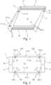
- Figure 1 shows a possible embodiment of a shelf 1 in a perspective view.
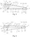
- Figures 2 and 3 show the shelf 1 in a top view ( Figure 2 ) and in a side view ( Figure 3 ).
- the shelf 1 comprises a top 2, a bottom 3, a front 4, a back 5 and two opposing side walls 6, 7.
- the top 2 forms a (in the Figure 3 uprising level 8 for goods (shown in dashed lines as an example).
- the shelf 1 can comprise a frame structure.
- the frame structure preferably has a front frame part 17, a rear frame part 18 and two side frame parts 19, 20 connecting the front frame part 17 and the rear frame part 18 to form a frame interior 21.
- the front frame part 17 of the front side 4 and the rear Frame part 18 is assigned to the rear side 5 of the shelf 1.
- the respective side section 6 or 7 of the shelf 1 is also arranged or formed on one of the side frame parts 19, 20.
- the front frame part 17 and the rear frame part 18 can be the same part.
- the front frame part 17 and/or the rear frame part 18 is U-shaped in cross section and is connected to the side frame parts 19, 20, for example by means of connecting means, in particular screw elements 22.
- the side frame parts 19, 20 can each be plate-shaped, for example be sheet metal parts.
- the shelf 1 comprises a (in the Figures 1 to 3 A pull-out device 9 (indicated by dashed lines) by means of which the shelf 1 can be pulled out relative to a support structure.
- a possible embodiment of such a support structure is shown in the Figure 2 and provided with the reference number 100.
- the pull-out device 9 is designed such that the shelf 1 executes or can execute a linear or essentially linear pull-out movement that runs at an angle of inclination ⁇ relative to its upper side 2.
- linear pull-out movement is to be understood in particular as a straight-line or essentially straight-line movement that is or can be executed by the shelf 1, for example in order to move the shelf 1 away from the support structure 100.
- the pull-out device 9 allows two aspects to be achieved, namely that on the one hand the shelf 1 can be pulled out and on the other hand it can be present as a so-called sliding floor.
- the sliding floor is achieved, for example, when the support level 8 and thus a support surface 8.1 located in the support level 8 is placed in such an inclined position relative to a horizontal that the sliding of goods placed on the support surface 8.1 is at least promoted or even caused. In this way, it is promoted or caused that the goods slide in the direction of the lower front side 4 of the shelf 1.
- the front side 4 is preferably the removal side for the goods.
- the support surface 8.1 preferably has a material that promotes slippage and/or is coated with such a material.
- the pull-out device 9 ensures that the shelf 1 can be pulled out relative to the support structure 100 while maintaining the inclined position of the support plane 8.
- the pull-out movement can take place in such a way that it runs in a horizontal direction or essentially linearly in a horizontal direction, so that the pulled-out shelf 1 can be pushed back with relatively little effort. Pushing back from a lower position to an upper position, i.e. against the effect of gravity, can be avoided in this way.
- the pull-out device 9 comprises a linear guide 10 arranged on the respective side section 6 or 7, as for example a rail guide.
- the linear guide 10 protrudes laterally outwards from the associated side section 6 or 7.
- the shelf 1 can have an adjusting device 13.
- the adjusting device 13 is used to adjust the angle of inclination ⁇ . This is possible in steps with the adjusting device 13, but can in principle also be implemented continuously.
- the adjusting device 13 comprises several fastening points 14 arranged on the respective side section 6 or 7 in order to be able to fasten the linear guide 10 thereto.
- the fastening points 14 are designed as a through opening, in particular a through hole, so that the linear guide 10 can be fastened thereto, for example by means of one or at least two screw elements or other fastening elements 11 and/or corresponding counter elements 11', such as a nut element.
- the fastening points 14 preferably comprise at least two first fastening points 14.1, 14.2 and at least two second fastening points 14.3, 14.4, wherein the at least two first fastening points 14.1, 14.2 are arranged at a distance from one another and the at least two second fastening points 14.3, 14.4 are also arranged at a distance from one another.
- the adjusting device 13 is now formed in that a first straight line 12.1 connecting the at least two first fastening points 14.1, 14.2 runs obliquely relative to the upper side 2 of the shelf 1 by a first value W1 of the angle of inclination ⁇ and a first straight line 12.1 connecting the at least two second fastening points 14.3, 14.4 connecting second straight line 12.2 is inclined relative to the top side 2 of the shelf 1 by a second value W2 of the inclination angle ⁇ .
- the linear guide 10 is mounted on the at least two first fastening points 14.1, 14.2, so that the extension device 9 is set to the first value W1 for the inclination angle ⁇ .
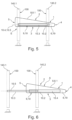
- the adjusting device 13 can comprise a setting in which the support plane 8 has no or essentially no inclination.
- the fastening points 14 can have at least two third fastening points 14.5, 14.6, which are arranged at a distance from one another and are aligned parallel or essentially parallel to the support plane 8.
- Figure 4 shows the shelf 1 in a side view, where the linear guide 10 is mounted on the at least two third fastening points 14.5, 14.6.
- the first fastening point 14.1 and the second fastening point 14.3 facing the front side 4 are formed by a common fastening point.
- the third fastening point 14.5 facing the front side 4 is also formed by the common fastening point.
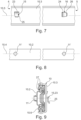
- Figure 5 shows the shelf 1 in an installed state on the support structure 100, which is indicated there by dashed lines.
- the shelf 1 is in a pushed-in position E on the support structure 100.
- Figure 6 shows the shelf 1 in the installed state of the Figure 5 , whereby in the Figure 6 the shelf 1 is in an extended position A relative to the support structure 100.
- the shelf 1 is attached to the support structure 100 via the pull-out device 9 or its linear guide 10.
- the linear guide 10 provided on the respective side section 6 or 7 is attached to the support structure 100.
- the pushed-in position E is a position of the shelf 1 relative to the support structure 100 in which the shelf 1 is permanently present, for example, in order to store and/or present goods on its support surface 8.1.
- the shelf 1 is locked in the pushed-in position E.
- a locking device can be provided on the shelf 1 and/or the support structure 100.
- the "pull-out position" is to be understood in particular as a position which the shelf 1 has relative to the support structure 100 after the shelf 1 has been pulled out by means of its pull-out device 9 and has assumed a final or intermediate position.
- the Figures 5 and 6 show the linear guide 10, which comprises two linear guide elements 10.2, 10.3.
- the linear guide elements 10.2, 10.3 can be moved relative to one another, in particular can be moved in a linearly guided manner relative to one another in order to be able to carry out the linear extension movement.
- the linear guide elements 10.2, 10.3 are each elongated, with their longitudinal axes 10.4, 10.5 lying on a common axis, so that the relative movement of the linear guide elements 10.2, 10.3 to one another takes place by a displacement on the common axis.
- the longitudinal axes 10.4, 10.5 are preferably arranged horizontally or essentially horizontally, so that the linear extension movement is correspondingly horizontal or essentially horizontal.
- One of the linear guide elements 10.2, 10.3, in particular the linear guide element 10.2, is fastened to the associated side section 6 or 7.
- the fastening elements 11 and/or counter elements 11' already described above are used for this purpose, which are for example in the Figures 1 to 4
- the other of the linear guide elements 10.2, 10.3, in particular the linear guide element 10.3, is attached to the support structure 100.
- the support structure 100 can comprise several, preferably four vertical supports 140.1, 140.2, 140.3, 140.4, which can be part of a shelving system.
- two of the vertical supports 140.1, 140.2, 140.3, 140.4 are each assigned to one of the side sections 6, 7 of the shelf 1.
- Figures 7 and 8 show the linear guide elements 10.2 and 10.3. At least two coupling points 15, 16 are provided on the linear guide element 10.3, which is designed to be attached to the support structure 100.
- the coupling points 15, 16 are preferably arranged at a distance with respect to the longitudinal axis 10.5 of the linear guide element 10.3.
- the coupling points 15, 16 are each arranged in an end region with respect to the longitudinal axis 10.5 of the linear guide element 10.3.
- the at least two coupling points 15, 16 each comprise a suspension tab 23, 24.
- the suspension tabs 23, 24 are attached to the linear guide element 10.3, in particular welded or molded onto it.
- the suspension tabs 23, 24 have one end which is attached or molded onto the linear guide element 10.3, and a tab section which can be used as an insertion section 25 or 26 in order to be able to hang and/or push the linear guide element 10.3 into a corresponding receptacle of the support structure 100 via the suspension tab 23 or 24.
- the insertion section 25 or 26 is formed by a material section which projects beyond the outside of the linear guide element 10.3 and overlaps the outside of the linear guide element 10.3 over at least one area in order to form the suspension tab 25 or 26 in this way.
- Insertion section 26 points in the direction of the rear side 5 of the shelf 1. It is further provided that in the case of the hanging tab 23, which faces the front side 4 of the shelf 1, the insertion section 25 points downwards, i.e. towards the underside 3 of the shelf 1.
- the shelf 1 can thus be fastened to the support structure 100 by a first insertion movement directed towards the rear side 5 and a subsequent second insertion movement directed downwards.
- the first insertion movement pushes the hanging tab 24 directed towards the rear side 5 into an associated receptacle on the support structure 100, with the first insertion movement taking place in the direction of the longitudinal axis 10.5 towards the rear side 5 of the shelf 1.
- the second insertion movement pushes the hanging tab 23 facing the front side 4 into the associated receptacle of the support structure 100, with the second insertion movement directed downwards.
- the Figure 8 shows the linear guide element 10.2 with the counter elements 11' already described above for fastening against the respective associated side section 6 or 7 ( Figures 1 and 2 ).
- the counter element 11' is formed by a weld nut or a press-in nut, which is fastened to the associated side section 6 or 7.
- the counter elements 11' are preferably arranged at a distance with respect to the longitudinal axis 10.4 of the linear guide element 10.2.
- FIG 9 shows a possible embodiment of the linear guide 10.
- the linear guide 10 is a telescopic linear guide, for example a telescopic rail guide.
- the linear guide element 10.2 is a Inner rail and the linear guide element 10.3 an outer rail surrounding the inner rail.
- at least one further linear guide element 10.6, in particular a rail element can be provided, which is arranged for example between the outer rail and the inner rail and thus forms a middle rail.
- the linear guide elements 10.2, 10.3 and 10.6 can be coupled to one another by rolling elements 27, so that a telescopic extension of the linear guide elements 10.2, 10.3 and 10.6 relative to one another is promoted by the rolling elements 27.
- the linear guide 10 according to the Figure 9 may have the coupling points 15 and 16 described above and/or the fastening elements or counter-elements 11' described above.
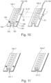
- Figure 10 shows a possible embodiment of a vertical support as a component of the support structure 100 for the shelf 1.
- a vertical support can be assigned twice to the respective side section 6 or 7 of the shelf 1.
- the two vertical supports assigned to the side section 6 are shown and provided with the reference numerals 140.1 ⁇ , 140.2 ⁇ .
- the vertical supports 140.1 ⁇ and 140.2 ⁇ can be designed identically to one another. For the sake of simplicity, reference is made below only to one of the two vertical supports, namely the vertical support 140.1 ⁇ .
- the vertical support 140.1 ⁇ is elongated and extends with its longitudinal extension in the vertical direction when the vertical support 140.1' is in the installed state, for example on a shelving system.
- the vertical support 140.1' has at least one, preferably several or a plurality of counter-coupling points 110 in order to couple the pull-out device 9 or linear guide 10 of the shelf 1 to it via their coupling points 15, 16.
- the counter-coupling points 110 are designed as a receptacle 130 for the suspension tabs 23 or 24, which in connection with the embodiment of the linear guide 10 to the Figure 7 is described.
- the receptacles 130 are formed as angular, in particular square or rectangular, entry openings into which the suspension tabs 25 and 26 can be inserted or hung.
- the counter-coupling points 110 are spaced apart from one another in the longitudinal direction of the vertical support 140.1 ⁇ , in particular arranged one behind the other in a row.
- the vertical support 140.1 ⁇ is, for example, a profile part and can be U-shaped in cross-section and have two legs 142, 143, which are connected to one another by an intermediate section 144.
- the counter-coupling points 110 are preferably formed on the intermediate section 144.
- the vertical support 140.1 ⁇ can have a flange section 145 pointing outwards to the side of the legs 142, 143, which adjoins, for example, the end of the respective leg 142 or 143.
- the respective flange section 144 can have at least one connection point 146 in order to fasten the vertical support 140.1 ⁇ to a counter-support and/or a wall.
- the shelf 1 is indicated with dashed lines, whereby the side section 6 is shown.
- the arrow 50 shows the first insertion movement and
- the arrow 51 indicates the second insertion movement in order to fasten the linear guide 10 to the support structure 100 or the vertical supports 140.1 ⁇ and 140.2 ⁇ , as described above.
- Figure 11 shows a further embodiment of a vertical support 140.1" or 140.2'', which is shown twice there.
- the vertical support 140.1" or 140.2" can correspond to the vertical support 140.1 ⁇ or 140.2".
- the vertical support 140.1" or 140.2 is the Figure 11 in its contour to be attached to another vertical support 141.1 or 141.2 while overlapping with its contour.
- the other vertical support 141.1 or 141.2 can be a shelf support with oblique slots into which a (in the Figure 11
- the design of the vertical supports 140.1" or 140.2" makes it possible to convert a shelf with other vertical supports 140.1 or 140.2 so that the pull-out shelf 1 can be used.
- reference to a particular aspect or embodiment or configuration means that a particular feature or characteristic described in connection with the respective aspect or embodiment or configuration is at least included therein, but not necessarily in all aspects or embodiments or configurations. the invention must be included.
Landscapes
- Assembled Shelves (AREA)
Description
Fachböden sind üblicherweise integraler Bestandteil von Regalen und beispielsweise an vertikalen Regalstützen seitlich befestigt. Die Fachböden weisen eine Auflagefläche auf, um darauf Waren zu lagern und/oder zu präsentieren. Die Auflagefläche ist häufig in einer Schräglage angeordnet, um ein Rutschen der darauf befindlichen Waren zu begünstigen. Dieses Prinzip der schiefen Ebene kommt zunehmend bei Verkaufsregalen zum Einsatz. Die Auflagefläche der Fachböden ist dort nach vorne in Richtung zu der Seite der Warenentnahme geneigt ausgerichtet, um beispielsweise ein selbsttätiges Nachrutschen von üblicherweise in einer Reihe hintereinanderliegend angeordneten Wareneinheiten zu bewirken, wenn eine vorneliegende Wareeinheit entnommen wurde.Shelves are usually an integral part of shelves and are attached to the sides of vertical shelf supports, for example. The shelves have a support surface on which goods can be stored and/or displayed. The support surface is often arranged at an angle to encourage the goods on it to slide. This principle of the inclined plane is increasingly used in sales shelves. The support surface of the shelves is inclined towards the front towards the side where the goods are removed, for example to cause goods units that are usually arranged in a row one behind the other to slide forward automatically when a goods unit at the front has been removed.
Eine mögliche Ausführungsform eines solchen Rutschregales ist aus der
Ein gattungsgemäßer Fachboden ist aus der
Eine Aufgabe der Erfindung ist es, einen Fachboden bereitzustellen, welcher andere Einbausituationen ermöglicht und eine Nutzung als Schrägfachboden erlaubt. Auch soll eine Anordnung eines derartigen Fachbodens an einer entsprechenden Trägerstruktur bereitgestellt werden.One object of the invention is to provide a shelf which enables other installation situations and allows use as a sloping shelf. An arrangement of such a shelf on a corresponding support structure should also be provided.
Die Aufgabe wird mit einem Fachboden gelöst, welcher die Merkmale des Anspruches 1 aufweist. Zur Lösung der Aufgabe wird ferner eine Anordnung mit den Merkmalen des Anspruches 6 vorgeschlagen. Vorteilhafte Ausführungsformen und/oder Ausgestaltungen und/oder Aspekte der Erfindung ergeben sich aus den Unteransprüchen, der nachfolgenden Beschreibung und den Figuren.The object is achieved with a shelf which has the features of
Ein grundlegender Fachboden umfasst eine Vorderseite, eine Rückseite und zwei einander gegenüberliegende Seitenabschnitte. Beispielsweise liegen die Seitenabschnitte zwischen der Vorderseite und der Rückseite und/oder die Seitenabschnitte erstrecken sich bis in den Bereich der Vorderseite und/oder der Rückseite und/oder bis an die Vorderseite und/oder die Rückseite.A basic shelf comprises a front, a back and two opposing side sections. For example, the side sections lie between the front and the back and/or the side sections extend into the area of the front and/or the back and/or up to the front and/or the back.
Der Fachboden umfasst ferner eine Oberseite, welche eine Aufstandsebene für Waren bildet. Beispielsweise ist die Oberseite durch die Vorderseite und/oder die Rückseite und/oder die Seitenabschnitte seitlich begrenzt. Beispielsweise ist die Aufstandsebene durch eine Aufstandsfläche gebildet, welche beispielsweise an einem insbesondere flächigen Aufstandsblech oder an wenigstens einem länglichen, sich in Längsrichtung zwischen der Vorderseite und der Rückseite erstreckenden Aufstandsprofil oder an einer Röllchenbahn oder dergleichen ausgebildet sein kann. Beispielsweise ist die Aufstandsfläche mit einer gleitfördernden Beschichtung versehen oder weist ein gleitförderndes Material auf oder besteht aus einem solchen Material.The shelf further comprises an upper side, which forms a support plane for goods. For example, the upper side is laterally delimited by the front side and/or the back side and/or the side sections. For example, the support plane is formed by a support surface, which can be formed, for example, on a support plate, in particular a flat support plate, or on at least one elongated support profile extending in the longitudinal direction between the front side and the back side, or on a roller conveyor or the like. For example, the contact surface is provided with a slip-promoting coating or has a slip-promoting material or consists of such a material.
Es ist den Seitenabschnitten eine Auszugseinrichtung zugeordnet, welche wenigstens zwei Koppelstellen zum Befestigen an einer Trägerstruktur für den Fachboden aufweist. Dadurch ist eine Einbausituation zu realisieren, in der der Fachboden gegenüber der Trägerstruktur ausziehbar ist.The side sections are assigned a pull-out device which has at least two coupling points for fastening to a support structure for the shelf. This makes it possible to create an installation situation in which the shelf can be pulled out relative to the support structure.
Unter der Bezeichnung "Vorderseite" ist in der vorliegenden Beschreibung insbesondere diejenige Seite des Fachbodens zu verstehen, von welcher aus eine Warenentnahme stattfinden soll und/oder welche eine Warenpräsentationsseite bildet. Unter der Bezeichnung "horizontal" ist in der vorliegenden Beschreibung insbesondere eine Erstreckung beispielsweise einer Ebene oder Strecke zu verstehen, welche rechtwinklig oder im Wesentlichen rechtwinklig zur Lotrichtung verläuft, also waagerecht oder im Wesentlichen waagerecht verläuft. Unter der Bezeichnung "vertikal" ist in der vorliegenden Beschreibung insbesondere eine Erstreckung beispielsweise einer Ebene oder Strecke zu verstehen, welche in Lotrichtung verläuft, also senkrecht oder im Wesentlichen senkrecht verläuft.In this description, the term "front side" is to be understood in particular as the side of the shelf from which goods are to be removed and/or which forms a side for displaying goods. In this description, the term "horizontal" is to be understood in particular as an extension, for example of a plane or line which runs at right angles or essentially at right angles to the vertical direction, i.e. runs horizontally or essentially horizontally. In this description, the term "vertical" is to be understood in particular as an extension, for example of a plane or line which runs in the vertical direction, i.e. runs perpendicular or essentially perpendicular.
Es ist vorgesehen, dass die Auszugseinrichtung eine, an dem jeweiligen Seitenabschnitt angeordnete Linearführung umfasst. Es ist ferner vorgesehen, dass die Linearführung wenigstens zwei relativ zueinander verschiebbare Linearführungselemente aufweist, von denen ein Linearführungselement an dem zugehörigen Seitenabschnitt befestigt ist und dem anderen Linearführungselement die wenigstens zwei Koppelstellen zugeordnet sind. Dadurch ist eine technisch einfache Realisierung der Auszugsfunktion des Fachbodens begünstigt. In diese Richtung zielt auch die Maßnahme, dass nach einer Ausgestaltung die Linearführung eine Schienenführung ist. In diesem Fall können die Linearführungselemente vorzugsweise jeweils als Schienenelement ausgebildet sein.It is provided that the pull-out device comprises a linear guide arranged on the respective side section. It is further provided that the linear guide has at least two linear guide elements that can be moved relative to one another, of which one linear guide element is attached to the associated side section and the other linear guide element has the at least two coupling points are assigned. This facilitates a technically simple implementation of the pull-out function of the shelf. The measure that, according to one design, the linear guide is a rail guide also aims in this direction. In this case, the linear guide elements can preferably each be designed as a rail element.
Es kann vorgesehen sein, dass die Linearführung eine Teleskop-Linearführung, insbesondere Teleskop-Schienenführung ist. Dadurch ist eine Maßnahme ergriffen, um den Fachboden gegenüber der Trägerstruktur über eine relativ lange Strecke ausziehen zu können, beispielsweise um die gesamte Fläche des Fachbodens möglichst gut erreichen zu können und damit das Befüllen des Fachbodens mit Waren zu erleichtern. Die Teleskop-Linearführung bzw. Teleskop-Schienenführung kann als Wälz- oder Gleitführung ausgeführt sein. Sofern es sich um eine Teleskop-Schienenführung handelt, kann neben einer Außenschiene und einer Innenschiene wenigstens eine dazwischenliegende Mittelschiene vorgesehen sein, welche beispielsweise über Wälzkörper miteinander gekoppelt und gegeneinander verfahrbar gelagert sind.It can be provided that the linear guide is a telescopic linear guide, in particular a telescopic rail guide. This is a measure to be able to extend the shelf over a relatively long distance relative to the support structure, for example in order to be able to reach the entire surface of the shelf as well as possible and thus make it easier to fill the shelf with goods. The telescopic linear guide or telescopic rail guide can be designed as a rolling or sliding guide. If it is a telescopic rail guide, in addition to an outer rail and an inner rail, at least one intermediate middle rail can be provided, which are coupled to one another, for example via rolling elements and mounted so that they can move relative to one another.
Nach einem Gedanken kann der Fachboden eine Arretiereinrichtung umfassen, welche eingerichtet ist, in einer eingeschobenen Position den Fachboden gegenüber der Trägerstruktur gegen ein Herausziehen zu sichern. Durch die Arretiereinrichtung ist eine Maßnahme ergriffen, um ein ungewolltes Ausziehen des Fachbodens zu vermeiden.According to one idea, the shelf can comprise a locking device which is designed to secure the shelf against being pulled out from the support structure in a pushed-in position. The locking device is a measure to prevent the shelf from being pulled out accidentally.
Bei einer weiteren Ausführungsform umfasst der Fachboden eine Rahmenstruktur, welche ein vorderes Rahmenteil, ein hinteres Rahmenteil und zwei, das vordere Rahmenteil und das hintere Rahmenteil unter Ausbildung eines Rahmeninnenraumes verbindende seitliche Rahmenteile aufweist. Es ist insbesondere vorgesehen, dass das vordere Rahmenteil der Vorderseite und das hintere Rahmenteil der Rückseite des Fachbodens zugeordnet sind. Auch ist es insbesondere vorgesehen, dass der jeweilige Seitenabschnitt des Fachbodens an jeweils einem der seitlichen Rahmenteile ausgebildet oder angeordnet ist. Dadurch ist ein modularer Aufbau des Fachbodens begünstigt.In a further embodiment, the shelf comprises a frame structure which has a front frame part, a rear frame part and two, the front frame part and the rear frame part has side frame parts connecting them to form a frame interior. It is particularly provided that the front frame part is assigned to the front side and the rear frame part to the back side of the shelf. It is also particularly provided that the respective side section of the shelf is formed or arranged on one of the side frame parts. This promotes a modular construction of the shelf.
Beispielsweise können das vordere Rahmenteil und das hintere Rahmenteil ein Modul bilden, welches beispielsweise ein Gleichteil ist. Ebenso können die seitlichen Rahmenteile ein Modul bilden, welches beispielsweise ein Gleichteil ist. Beispielsweise sind die seitlichen Rahmenteile durch ein plattenförmiges Bauteil, insbesondere Blechteil gebildet. Ein weiteres Modul kann durch eine, eine Auflagefläche für Waren aufweisende Warenauflage gebildet sein, wobei die Warenauflage durch ein einziges Bauteil oder mehrere oder eine Vielzahl von Bauteilen gebildet sein kann.For example, the front frame part and the rear frame part can form a module, which is, for example, an identical part. The side frame parts can also form a module, which is, for example, an identical part. For example, the side frame parts are formed by a plate-shaped component, in particular a sheet metal part. A further module can be formed by a goods support having a support surface for goods, whereby the goods support can be formed by a single component or several or a large number of components.
Das vordere Rahmenteil und/oder das hintere Rahmenteil kann ein Fachbodenelement sein, wie es in der
Beispielsweise weist das Fachbodenelement an seinem Grundkörper eine Vielzahl von länglichen Durchgangsöffnungen auf, welche mit ihrer Längserstreckung quer zur Längserstreckung des Grundkörpers verlaufen. Beispielsweise sind die Durchgangsöffnungen zueinander im Wesentlichen parallel verlaufend und insbesondere in einer Reihe hintereinanderliegend angeordnet. Beispielsweise ist der Grundkörper im Querschnitt u-förmig ausgebildet und die Durchgangsöffnungen erstrecken sich bis in einen der Schenkel und in ein die Schenkel der U-Form verbindenden Zwischenabschnitt des Grundkörpers. In den Durchgangsöffnungen können Warentrenner befestigt werden, beispielsweise indem ein Ende eines Warentrenners, insbesondere ein plattenförmiges Ende in eine der Durchgangsöffnungen eingesteckt wird.For example, the shelf element has a large number of elongated through-openings on its base body, the longitudinal extent of which runs transversely to the longitudinal extent of the base body. For example, the through-openings run essentially parallel to one another and are arranged in particular in a row one behind the other. For example, the base body is U-shaped in cross-section and the through-openings extend into one of the legs and into an intermediate section of the base body that connects the legs of the U-shape. Product dividers can be attached in the through-openings, for example by inserting one end of a product divider, in particular a plate-shaped end, into one of the through-openings.
Das wenigstens eine seitliche Rahmenteil kann ein Seitenteil sein, wie es in der
Weitere Einzelheiten und Merkmale der Erfindung ergeben sich aus der nachfolgenden Beschreibung mehrerer Ausführungsbeispiele anhand der Zeichnung. Es zeigen
- Fig. 1
- eine mögliche Ausführungsform eines ausziehbaren Fachbodens in perspektivischer Darstellung von unten,
- Fig. 2
- den Fachboden gemäß der
Figur 1 - Fig. 3
- den Fachboden der
Figur 1 - Fig. 4
- den Fachboden gemäß der
Figur 1 - Fig. 5
- den Fachboden der
Figur 1 - Fig. 6
- den
Fachboden der Figur 1 in derAnordnung der Figur 5 , wobei sich der Fachboden in einer ausgezogenen Position befindet, - Fig. 7
- ein Linearführungselement einer Auszugseinrichtung für den Fachboden der
Fig. 1 mit Einhängelaschen in einer Seitenansicht, - Fig. 8
- eines weiteres Linearführungselement der Auszugseinrichtung für den Fachboden der
Fig. 1 mit Befestigungselementen in einer Seitenansicht, - Fig. 9
- eine Linearführung für den Fachboden der
Fig. 1 in einer Vorderansicht, - Fig. 10
- eine Vertikalstütze als Bestandteil einer Trägerstruktur für den Fachboden nach der
Figur 1 in perspektivischer Darstellung und - Fig. 11
- eine weitere Vertikalstütze als Bestandteil einer Trägerstruktur für den Fachboden nach der
Figur 1 in perspektivischer Darstellung.
- Fig. 1
- a possible embodiment of a pull-out shelf in perspective view from below,
- Fig. 2
- the shelf according to the
Figure 1 in a top view, - Fig. 3
- the shelf of the
Figure 1 in a side view, with a support plane of the shelf in a forward-sloping orientation, - Fig. 4
- the shelf according to the
Figure 1 in a side view, with the contact surface in a horizontal position, - Fig. 5
- the shelf of the
Figure 1 , mounted on a supporting structure, in an inserted position as a side view in a partial section, - Fig. 6
- the shelf of the
Figure 1 in the arrangement of theFigure 5 , with the shelf in an extended position, - Fig. 7
- a linear guide element of a pull-out device for the shelf of the
Fig. 1 with hanging tabs in a side view, - Fig. 8
- another linear guide element of the pull-out device for the shelf of the
Fig. 1 with fastening elements in a side view, - Fig. 9
- a linear guide for the shelf of the
Fig. 1 in a front view, - Fig. 10
- a vertical support as part of a support structure for the shelf according to the
Figure 1 in perspective representation and - Fig. 11
- another vertical support as part of a support structure for the shelf after the
Figure 1 in perspective view.
Der Fachboden 1 kann eine Rahmenstruktur umfassen. Bevorzugt weist die Rahmenstruktur dann ein vorderes Rahmenteil 17, ein hinteres Rahmenteil 18 und zwei, das vordere Rahmenteil 17 und das hintere Rahmenteil 18 unter Ausbildung eines Rahmeninnenraums 21 verbindende seitliche Rahmenteile 19, 20 auf. Bevorzugt ist in diesem Fall das vordere Rahmenteil 17 der Vorderseite 4 und das hintere Rahmenteil 18 der Rückseite 5 des Fachbodens 1 zugeordnet. Bevorzugt ist ferner der jeweilige Seitenabschnitt 6 bzw. 7 des Fachbodens 1 an jeweils einem der seitlichen Rahmenteile 19, 20 angeordnet bzw. ausgebildet. Das vordere Rahmenteil 17 und das hintere Rahmenteil 18 können ein Gleichteil sein. Beispielsweise ist das vordere Rahmenteil 17 und/oder das hintere Rahmenteil 18 im Querschnitt U-förmig ausgebildet und beispielsweise mittels Verbindungsmitteln, insbesondere Schraubelementen 22, mit den seitlichen Rahmenteilen 19, 20 verbunden. Die seitlichen Rahmenteile 19, 20 können jeweils plattenförmig ausgebildet sein, beispielsweise Blechteile sein.The
Weiterhin umfasst der Fachboden 1 eine (in den
Die Auszugseinrichtung 9 ist derart eingerichtet, dass der Fachboden 1 eine gegenüber seiner Oberseite 2 um einen Neigungswinkel α schräg verlaufende lineare oder im wesentlichen lineare Auszugsbewegung ausführt oder ausführen kann. Unter der Bezeichnung "lineare Auszugsbewegung" ist in der vorliegenden Beschreibung insbesondere eine geradlinige oder im Wesentlichen geradlinige Bewegung zu verstehen, welche von dem Fachboden 1 ausgeführt wird oder werden kann, beispielsweise um den Fachboden 1 von der Trägerstruktur 100 weg zu bewegen.The pull-out device 9 is designed such that the
Durch die Auszugseinrichtung 9 lassen sich zwei Aspekte realisieren, dass nämlich zum einen der Fachboden 1 ausziehbar ist und zum anderen als sogenannter Rutschboden vorliegen kann. Der Rutschboden ist beispielsweise erreicht, wenn die Aufstandsebene 8 und damit eine in der Aufstandsebene 8 liegende Aufstandsfläche 8.1 relativ gegenüber einer Horizontalen in eine solche Schräglage gebracht ist, dass ein Nachrutschen von auf der Aufstandsfläche 8.1 aufgesetzten Waren zumindest begünstigt oder sogar bewirkt. Es ist auf diese Art und Weise begünstigt oder bewirkt, dass die Waren in Richtung zu der tieferliegenden Vorderseite 4 des Fachbodens 1 rutschen. Bevorzugt ist die Vorderseite 4 die Entnahmeseite für die Waren. Durch das Nachrutschen befinden sich durchgängig Waren in dem Bereich der Entnahme, so dass auf diese Art und Weise eine Warenpräsentation in diesem Bereich begünstigt ist. Bevorzugt weist dazu die Aufstandsfläche 8.1 ein rutschförderndes Material aufweist und/oder ist mit einem solchen Material beschichtet.The pull-out device 9 allows two aspects to be achieved, namely that on the one hand the
Durch die Auszugseinrichtung 9 ist es erreicht, dass der Fachboden 1 gegenüber der Trägerstruktur 100 ausgezogen werden kann und dabei die Schräglage der Aufstandsebene 8 beibehalten bleibt. Die Auszugsbewegung kann derart stattfinden, dass sie in horizontaler Richtung oder im Wesentlichen in horizontaler Richtung linear verläuft, so dass ein Zurückschieben des ausgezogenen Fachbodens 1 mit relativ geringem Kraftaufwand möglich ist. Ein Zurückschieben von einer unteren Position zu einer oberen Position, also gegen eine Schwerkraftwirkung, lässt sich auf diese Art und Weise vermeiden.The pull-out device 9 ensures that the
Die Auszugseinrichtung 9 umfasst eine, an dem jeweiligen Seitenabschnitt 6 bzw. 7 angeordnete Linearführung 10, wie beispielsweise eine Schienenführung. Bevorzugt ragt die Linearführung 10 von dem zugehörigen Seitenabschnitt 6 bzw. 7 seitlich nach außen hervor.The pull-out device 9 comprises a
Wie insbesondere aus der
Bevorzugt umfassen die Befestigungsstellen 14 wenigstens zwei erste Befestigungsstellen 14.1, 14.2 und wenigstens zwei zweite Befestigungsstellen 14.3, 14.4, wobei die wenigstens zwei ersten Befestigungsstellen 14.1, 14.2 in einem Abstand zueinander angeordnet sind und ebenso die wenigstens zwei zweiten Befestigungsstellen 14.3, 14.4 in einem Abstand zueinander angeordnet sind. Die Stelleinrichtung 13 ist nunmehr dadurch gebildet, dass eine die wenigstens zwei ersten Befestigungsstellen 14.1, 14.2 verbindende erste Gerade 12.1 gegenüber der Oberseite 2 des Fachbodens 1 um einen ersten Wert W1 des Neigungswinkels α schräg verlaufend ist und eine die wenigstens zwei zweiten Befestigungsstellen 14.3, 14.4 verbindende zweite Gerade 12.2 gegenüber der Oberseite 2 des Fachbodens 1 um einen zweiten Wert W2 des Neigungswinkels α schräg verlaufend ist. In der
Die Stelleinrichtung 13 kann eine Einstellung umfassen, in welcher die Aufstandsebene 8 keine oder im Wesentlichen keine Schräglage aufweist. Dazu können die Befestigungsstellen 14 wenigstens zwei dritte Befestigungsstellen 14.5, 14.6 aufweisen, welche in einem Abstand zueinander angeordnet sind und parallel oder im Wesentlichen parallel zu der Aufstandsebene 8 ausgerichtet sind.
Bevorzugt sind eine der ersten Befestigungsstellen 14.1, 14.2, insbesondere die eine erste Befestigungsstelle 14.1, und eine der zweiten Befestigungsstellen 14.3, 14.4, insbesondere die eine zweite Befestigungsstelle 14.3, der Vorderseite 4 zugewandt und die andere der ersten Befestigungsstellen 14.1, 14.2, insbesondere die eine erste Befestigungsstelle 14.2, und die andere der zweiten Befestigungsstellen 14.3, 14.4, insbesondere die eine zweite Befestigungsstelle 14.4, der Rückseite 5 des Fachbodens 1 zugewandt. Bevorzugt sind die der Vorderseite 4 zugewandten erste Befestigungsstelle 14.1 und zweite Befestigungsstelle 14.3 durch eine gemeinsame Befestigungsstelle gebildet. Bevorzugt ist auch die der Vorderseite 4 zugewandte dritte Befestigungsstelle 14.5 durch die gemeinsame Befestigungsstelle gebildet.Preferably, one of the first fastening points 14.1, 14.2, in particular the one first fastening point 14.1, and one of the second fastening points 14.3, 14.4, in particular the one second fastening point 14.3, face the
Beispielsweise handelt es sich bei der eingeschobenen Position E um eine Position des Fachbodens 1 relativ gegenüber der Trägerstruktur 100, in welcher der Fachboden 1 beispielsweise dauerhaft vorliegt, um auf seiner Aufstandsfläche 8.1 Waren zu lagern und/oder zu präsentieren. Beispielsweise ist der Fachboden 1 in der eingeschobenen Position E arretiert. Dazu kann eine Arretiervorrichtung an dem Fachboden 1 und/oder der Trägerstruktur 100 vorgesehen sein. Unter der "ausgezogenen Position" ist in der vorliegenden Beschreibung insbesondere eine Position zu verstehen, welche der Fachboden 1 relativ gegenüber der Trägerstruktur 100 aufweist, nachdem der Fachboden 1 mittels seiner Auszugseinrichtung 9 ausgezogen wurde und eine End- oder Zwischenposition eingenommen hat.For example, the pushed-in position E is a position of the
Die
Eines der Linearführungselemente 10.2, 10.3, insbesondere das Linearführungselement 10.2, ist an dem zugehörigen Seitenabschnitt 6 bzw. 7 befestigt. Bevorzugt sind dazu die bereits vorstehend beschriebenen Befestigungselemente 11 und/oder Gegenelemente 11' genutzt, welche beispielsweise in den
Die Trägerstruktur 100 kann mehrere, vorzugsweise vier Vertikalstützen 140.1, 140.2, 140.3, 140.4 umfassen, welche Bestandteil eines Regalsystems sein können. Beispielsweise sind jeweils zwei der Vertikalstützen 140.1, 140.2, 140.3, 140.4 jeweils einem der Seitenabschnitte 6, 7 des Fachbodens 1 zugeordnet. Beispielsweise ist eines der Linearführungselemente 10.2, 10.3, insbesondere das Linearführungselement 10.3, an den jeweils zwei zugehörigen Vertikalstützen 140.1, 140.2 bzw. 140.3, 140.4 angeordnet.The
Die wenigstens zwei Koppelstellen 15, 16 umfassen jeweils eine Einhängelasche 23, 24. Beispielsweise sind die Einhängelaschen 23, 24 an dem Linearführungselement 10.3 befestigt, insbesondere angeschweißt oder daran angeformt. Die Einhängelaschen 23, 24 haben ein Ende, welches an dem Linearführungselement 10.3 befestigt bzw. angeformt ist, und einen Laschenabschnitt, welcher als Einsteckabschnitt 25 bzw. 26 nutzbar ist, um über die Einhängelasche 23 bzw. 24 das Linearführungselement 10.3 in eine entsprechende Aufnahme der Trägerstruktur 100 einhängen und/oder einschieben zu können. Beispielsweise ist der Einsteckabschnitt 25 bzw. 26 durch einen Materialabschnitt gebildet, welcher über die Außenseite des Linearführungselementes 10.3 übersteht und zumindest über einen Bereich die Außenseite des Linearführungselementes 10.3 überlappt, um auf diese Art und Weise die Einhängelasche 25 bzw. 26 zu bilden.The at least two
Es ist vorgesehen, dass bei der Einhängelasche 24, welche der Rückseite 5 des Fachbodens 1 zugewandt ist, der Einsteckabschnitt 26 in Richtung zu der Rückseite 5 des Fachbodens 1 weist. Es ist ferner vorgesehen, dass bei der Einhängelasche 23, welche der Vorderseite 4 des Fachbodens 1 zugewandt ist, der Einsteckabschnitt 25 nach unten, also zur Unterseite 3 des Fachbodens 1, weist. Dadurch ist der Fachboden 1 an der Trägerstruktur 100 durch eine in Richtung zu der Rückseite 5 gerichtete erste Einsteckbewegung und eine anschließende nach unten gerichtete zweite Einsteckbewegung zu befestigen. Durch die erste Einsteckbewegung wird die zur Rückseite 5 gerichtete Einhängelasche 24 in eine zugehörige Aufnahme an der Trägerstruktur 100 eingeschoben, indem die erste Einsteckbewegung in Richtung der Längsachse 10.5 zu der Rückseite 5 des Fachbodens 1 stattfindet. Durch die zweite Einsteckbewegung wird die der Vorderseite 4 zugewandte Einhängelasche 23 in die zugehörige Aufnahme der Trägerstruktur 100 eingesteckt, indem die zweite Einsteckbewegung nach unten gerichtet ist.It is intended that the hanging
Die
Bevorzugt weist die Vertikalstütze 140.1' wenigstens eine, vorzugsweise mehrere oder eine Vielzahl von Gegenkoppelstellen 110 auf, um daran die Auszugseinrichtung 9 bzw. Linearführung 10 des Fachbodens 1 über deren Koppelstellen 15, 16 daran zu koppeln. Beispielsweise sind dazu die Gegenkoppelstellen 110 als Aufnahme 130 für die Einhängelaschen 23 bzw. 24 ausgebildet, welche im Zusammenhang mit der Ausführungsform der Linearführung 10 zu der
Die Vertikalstütze 140.1` ist beispielsweise ein Profilteil und kann im Querschnitt U-förmig ausgebildet sein und zwei Schenkel 142, 143 aufweisen, welche durch einen Zwischenabschnitt 144 miteinander verbunden sind. Bevorzugt sind an dem Zwischenabschnitt 144 die Gegenkoppelstellen 110 ausgebildet. Die Vertikalstütze 140.1` kann seitlich von den Schenkeln 142, 143 nach außen weisend jeweils einen Flanschabschnitt 145 aufweisen, welcher sich beispielsweise an das Ende des jeweiligen Schenkels 142 bzw. 143 anschließt. Der jeweilige Flanschabschnitt 144 kann wenigstens eine Anbindungsstelle 146 aufweisen, um die Vertikalstütze 140.1` gegen eine Gegenstütze und/oder eine Wandung zu befestigen.The vertical support 140.1` is, for example, a profile part and can be U-shaped in cross-section and have two
In der
Im Unterschied zu der Vertikalstütze 140.1` bzw. 140.2` der
In der vorliegenden Beschreibung bedeutet die Bezugnahme auf einen bestimmten Aspekt oder eine bestimmte Ausführungsform oder eine bestimmte Ausgestaltung, dass ein bestimmtes Merkmal oder eine bestimmte Eigenschaft, die in Verbindung mit dem jeweiligen Aspekt oder der jeweiligen Ausführungsform oder der jeweiligen Ausgestaltung beschrieben ist, zumindest dort enthalten ist, aber nicht notwendigerweise in allen Aspekten oder Ausführungsformen oder Ausgestaltungen der Erfindung enthalten sein muss.In the present description, reference to a particular aspect or embodiment or configuration means that a particular feature or characteristic described in connection with the respective aspect or embodiment or configuration is at least included therein, but not necessarily in all aspects or embodiments or configurations. the invention must be included.
Die Verwendung von einzelnen oder allen Beispielen oder einer beispielhaften Ausdrucksweise im Text soll lediglich die Erfindung beleuchten und stellt keine Beschränkung hinsichtlich des Umfangs der Erfindung dar, wenn nichts anders behauptet wird. Auch ist keine Ausdrucksweise oder Formulierung der Beschreibung so zu verstehen, dass es sich um ein nicht beanspruchtes, aber für die Praxis der Erfindung wesentliches Element handelt ist.The use of any or all examples or exemplary language in the text is intended to be merely illustrative of the invention and is not intended to be a limitation on the scope of the invention unless otherwise stated. Nor should any language or phrase of the specification be construed as an unclaimed but essential element to the practice of the invention.
- 11
- Fachbodenshelf
- 22
- Oberseitetop
- 33
- Unterseitebottom
- 44
- Vorderseitefront
- 55
- Rückseiteback
- 66
- Seitenabschnittside section
- 77
- Seitenabschnittside section
- 88
- Aufstandsebeneuprising level
- 8.18.1
- Aufstandsflächecontact area
- 99
- Auszugseinrichtungpull-out device
- 1010
- Linearführunglinear guide
- 10.110.1
-
Längsachse der Linearführung 10longitudinal axis of the
linear guide 10 - 10.210.2
- Linearführungselementlinear guide element
- 10.310.3
- Linearführungselementlinear guide element
- 10.410.4
- Längsachselongitudinal axis
- 10.510.5
- Längsachselongitudinal axis
- 10.610.6
- Linearführungselementlinear guide element
- 1111
- Befestigungselementfastener
- 11'11'
- Gegenbefestigungselementcounter-fastening element
- 12.112.1
- erste Geradefirst straight
- 12.212.2
- zweite Geradesecond straight
- 12.312.3
- dritte Geradethird straight
- 1313
- Stelleinrichtungactuator
- 1414
- Befestigungsstelleattachment point
- 14.114.1
- erste Befestigungsstellefirst attachment point
- 14.214.2
- erste Befestigungsstellefirst attachment point
- 14.314.3
- zweite Befestigungsstellesecond attachment point
- 14.414.4
- zweite Befestigungsstellesecond attachment point
- 14.514.5
- dritte Befestigungsstellethird attachment point
- 14.614.6
- dritte Befestigungsstellethird attachment point
- 1515
- Koppelstellecoupling point
- 1616
- Koppelstellecoupling point
- 1717
- vorderes Rahmenteilfront frame part
- 1818
- hinteres Rahmenteilrear frame part
- 1919
- seitliches Rahmenteilside frame part
- 2020
- seitliches Rahmenteilside frame part
- 2121
- Rahmeninnenraumframe interior
- 2222
- Schraubelementscrew element
- 2323
- Einhängelaschehanging tab
- 2424
- Einhängelaschehanging tab
- 2525
- Einsteckabschnittinsertion section
- 2626
- Einsteckabschnittinsertion section
- 2727
- Wälzkörperrolling elements
- 5050
- PfeilArrow
- 5151
- PfeilArrow
- 100100
- Trägerstruktursupport structure
- 110110
- Gegenkoppelstellenegative feedback point
- 130130
- AufnahmeRecording
- 140.1140.1
- Vertikalstützevertical support
- 140.2140.2
- Vertikalstützevertical support
- 140.1'140.1'
- Vertikalstützevertical support
- 140.2'140.2'
- Vertikalstützevertical support
- 140.1"140.1"
- Vertikalstützevertical support
- 140.2"140.2"
- Vertikalstützevertical support
- 140.3140.3
- Vertikalstützevertical support
- 140.4140.4
- Vertikalstützevertical support
- 141.1141.1
- andere Vertikalstützeother vertical support
- 141.2141.2
- andere Vertikalstützeother vertical support
- 142142
- Schenkelleg
- 143143
- Schenkelleg
- 144144
- Zwischenabschnittintermediate section
- 145145
- Flanschabschnittflange section
- 146146
- Anbindungsstelleconnection point
- αα
- Neigungswinkelangle of inclination
- W1W1
- erster Wertfirst value
- W2W2
- zweiter Wertsecond value
- EE
- eingeschobene Positionretracted position
- AA
- ausgezogene Positionextended position
Claims (8)
- A shelf (1), comprisinga top side (2), a bottom side (3), a front side (4), a rear side (5) and two opposite lateral parts (6, 7), the top side (2) forming a support plane (8) for goods,a pull-out device (9) by means of which the shelf (1) can be pulled out relative to a support structure (100) and which is configured such that the shelf (1) executes or can execute a linear or substantially linear pull-out movement which is inclined by an angle of inclination (α) relative to its top side (2),wherein the pull-out device (9) comprises a linear guide (10) which is arranged on the respective lateral part (6; 7) and has two linear guide elements (10.2, 10.3) which can be displaced relative to one another, wherein one of these linear guide elements (10.2) is attached to the associated lateral part (6; 7) and the other linear guide element (10.3) is configured to be attached to the support structure (100), and two coupling points (15, 16) are provided on the other linear guide element (10.3) for this purpose,wherein the two coupling points (15, 16) each comprise a hook-in lug (23; 24), wherein the hook-in lugs (23, 24) have an end which is attached or integrally formed on the other linear guide element (10.3) and a lug part which can be used as an insertion part (25; 26) in order to be able to hook and/or push the other linear guide element (10.3) into a corresponding receptacle of the support structure (100) via the hook-in lug (23; 24),characterized in that the one hook-in lug (24) faces the rear side (5) of the shelf (1) and the other hook-in lug (23) faces the front side (4) of the shelf (1) and wherein, in the case of the hook-in lug (24) facing the rear side (5) of the shelf (1) the insertion part (26) points in the direction of the rear side (5) of the shelf (1), and in the case of the hook-in lug (23) facing the front side (4) of the shelf (1), the insertion part (25) points downwards towards the bottom side (3) of the shelf (1),whereby the shelf (1) can be attached to the support structure (100) by a first insertion movement directed towards the rear side (5) of the shelf (1) and a subsequent second insertion movement directed downwards,wherein, by the first insertion movement, the hook-in lug (24) facing the rear side (5) of the shelf (1) is inserted into an associated receptacle of the support structure (100), by the first insertion movement being carried out in the direction of the longitudinal axis (10.5) of the other linear guide element (10.3) towards the rear side (5) of the shelf (1), andwherein, by the second insertion movement, the hook-in lug (23) facing the front side (4) of the shelf (1) is inserted into an associated receptacle of the support structure (100), by the second insertion movement being directed downwards.
- The shelf according to claim 1, wherein the linear guide (10) is a rail guide.
- The shelf according to claim 1 or 2, wherein the linear guide (10) is a telescopic linear guide.
- The shelf according to one of the preceding claims, comprising an adjusting device (13) for adjusting the angle of inclination (α) in steps,wherein the adjusting device (13) comprises a plurality of attachment points (14) arranged on the respective lateral part (6; 7) in order to be able to fasten the linear guide (10) thereto, and the attachment points (14) comprise at least two first attachment points (14.1, 14.2) and at least two second attachment points (14.3, 14.4),wherein the at least two first attachment points (14.1, 14.2) are arranged at a distance from one another and the at least two second attachment points (14.3, 14.4) are also arranged at a distance from one another, andwherein the adjusting device (13) is formed by a first straight line (12.1) connecting the at least two first attachment points (14.1, 14.2) inclined relative to the top side (2) of the shelf (1) by a first value (W1) of the angle of inclination (α) and a second straight line (12.2) connecting the at least two second attachment points (14.3, 14.4) inclined relative to the top side (2) of the shelf (1) by a second value (W2) of the angle of inclination (α).
- The shelf according to one of the preceding claims, comprising a frame structure which has a front frame part (17), a rear frame part (18) and two lateral frame parts (19, 20) connecting the front frame part (17) and the rear frame part (18) while forming a frame interior (21), wherein the front frame part (17) is associated with the front side (4) and the rear frame part (18) is associated with the rear side (5) of the shelf (1) and the respective lateral part (6; 7) of the shelf (1) is respectively formed on one of the lateral frame parts (19, 20).
- An arrangement of a shelf (1) according to one of the preceding claims on a support structure (100), wherein the shelf (1) is attached to the support structure (100) via the pull-out device (9) and can be brought from an inserted position (E) on the support structure (100) into a pulled-out position (A) relative to the support structure (100).
- The arrangement according to claim 6, the support structure (100) comprising four vertical supports (140.1, 140.2, 140.3, 140.4), which have an elongated form and, in the installed state, extend with their longitudinal extension in the vertical direction and each have a plurality of mating coupling points (110) in order to couple the pull-out device (9) of the shelf (1) thereto via their coupling points (15, 16), wherein two of the vertical supports (140.1, 140.2, 140.3, 140.4) are respectively associated with one of the lateral parts (6, 7) of the shelf (1).
- The arrangement according to claim 7, wherein the mating coupling points (110) of the respective vertical support (140.1; 140.2; 140.3, 140.4) are arranged one behind the other in the longitudinal direction of the associated vertical support (140.1; 140.2; 140.3, 140.4).
Applications Claiming Priority (2)
| Application Number | Priority Date | Filing Date | Title |
|---|---|---|---|
| DE102018104809.2A DE102018104809A1 (en) | 2018-03-02 | 2018-03-02 | Shelf and shelf arrangement |
| PCT/DE2019/100175 WO2019166059A1 (en) | 2018-03-02 | 2019-02-27 | Shelf and shelf arrangement |
Publications (3)
| Publication Number | Publication Date |
|---|---|
| EP3758552A1 EP3758552A1 (en) | 2021-01-06 |
| EP3758552B1 true EP3758552B1 (en) | 2025-01-01 |
| EP3758552C0 EP3758552C0 (en) | 2025-01-01 |
Family
ID=65763232
Family Applications (1)
| Application Number | Title | Priority Date | Filing Date |
|---|---|---|---|
| EP19710596.8A Active EP3758552B1 (en) | 2018-03-02 | 2019-02-27 | Shelf and shelf arrangement |
Country Status (3)
| Country | Link |
|---|---|
| EP (1) | EP3758552B1 (en) |
| DE (2) | DE102018104809A1 (en) |
| WO (1) | WO2019166059A1 (en) |
Families Citing this family (1)
| Publication number | Priority date | Publication date | Assignee | Title |
|---|---|---|---|---|
| DE102020113239A1 (en) | 2020-05-15 | 2021-11-18 | Rickard Nilsson | Shelf support and process for their production, shelf system and room cell |
Family Cites Families (10)
| Publication number | Priority date | Publication date | Assignee | Title |
|---|---|---|---|---|
| DE3718952A1 (en) * | 1987-06-05 | 1988-12-22 | Linde Ag | GOODS SALES SHELF |
| DE20114098U1 (en) | 2001-08-25 | 2001-12-20 | Nilsson, Rickard, 65582 Diez | Freestanding variable slide shelf system |
| US7063219B2 (en) * | 2003-02-03 | 2006-06-20 | Viking Range Corporation | Adjustable wine rack |
| DE10309305A1 (en) * | 2003-03-04 | 2004-09-23 | Hertel, Günther | Fresh snacks and unwrapped bread dispensing device, comprising hood to be opened for refilling when shelf is moved |
| DE202006001832U1 (en) * | 2006-02-06 | 2006-04-20 | BSH Bosch und Siemens Hausgeräte GmbH | Refrigerating appliance with shelf |
| DE102008018235A1 (en) * | 2008-04-10 | 2009-10-15 | BSH Bosch und Siemens Hausgeräte GmbH | The refrigerator |
| AT512009B1 (en) * | 2011-10-13 | 2014-04-15 | Metzler Gmbh & Co Kg | DEVICE FOR STORING UTENSILS, ESPECIALLY TOOLS |
| DE102014209110A1 (en) * | 2014-05-14 | 2015-11-19 | Gebr. Willach Gmbh | Inclined shelving |
| DE102014109854A1 (en) | 2014-07-14 | 2016-01-14 | Rickard Nilsson | Shelf element for a shelf of a shelf, in particular slide shelves, as well as shelf frame, shelf and shelf |
| CA3032040A1 (en) * | 2016-07-25 | 2018-02-01 | Marmon Retail Store Equipment LLC | Merchandiser and methods relating to same |
-
2018
- 2018-03-02 DE DE102018104809.2A patent/DE102018104809A1/en not_active Withdrawn
-
2019
- 2019-02-27 EP EP19710596.8A patent/EP3758552B1/en active Active
- 2019-02-27 WO PCT/DE2019/100175 patent/WO2019166059A1/en not_active Ceased
- 2019-02-27 DE DE112019001099.9T patent/DE112019001099A5/en active Pending
Also Published As
| Publication number | Publication date |
|---|---|
| DE102018104809A1 (en) | 2019-09-05 |
| DE112019001099A5 (en) | 2020-11-12 |
| EP3758552A1 (en) | 2021-01-06 |
| EP3758552C0 (en) | 2025-01-01 |
| WO2019166059A1 (en) | 2019-09-06 |
Similar Documents
| Publication | Publication Date | Title |
|---|---|---|
| DE69924893T2 (en) | cabinet | |
| EP3569108B1 (en) | Shelf system to be fitted in a vehicle | |
| EP3420857B1 (en) | Cold storage room with shelving system | |
| EP3758552B1 (en) | Shelf and shelf arrangement | |
| DE2353471A1 (en) | CABLE TRAY WITH CONNECTOR | |
| EP0063805A2 (en) | Rack for storing and displaying articles | |
| DE19737673C5 (en) | Control cabinet with a transport lock | |
| EP2324732B1 (en) | Storage rack, in particular automatic small part storage | |
| DE102015112039A1 (en) | Frame for emergency batteries | |
| DE3120263C2 (en) | Front pull-out for a tall cabinet, especially a tall kitchen cabinet | |
| EP3850986B1 (en) | Cupboard pull-out for a cupboard element | |
| DE202018101195U1 (en) | Shelf and shelf arrangement | |
| EP3685705A1 (en) | Profile for building operating devices and operating device | |
| EP3072415A1 (en) | Furniture fitting for forming an extractable waste collection device and cabinet with such a furniture fitting | |
| EP1033093A1 (en) | Bracket for attachment of baskets, basins or trays between vertical shoulders of frames for vertical drawers | |
| EP0958759B1 (en) | Shelf system | |
| EP0534330B1 (en) | Rack for luggage, hats and the like, especially for installation in railway carriages | |
| DE102021006385B4 (en) | Wall mounting system with rail and support element | |
| DE202018101194U1 (en) | Shelf and shelf arrangement | |
| DE202018101196U1 (en) | Shelf and shelf arrangement | |
| EP1661491A1 (en) | Support frame | |
| DE9104837U1 (en) | Frame brace for a pull-out hanging file frame | |
| DE10041987B4 (en) | Telescopic pull-out guide | |
| EP4286628A1 (en) | Fastening adapter for double-rod grid mats | |
| EP4712820A1 (en) | Skirting board system, and piece of furniture comprising a skirting board system |
Legal Events
| Date | Code | Title | Description |
|---|---|---|---|
| STAA | Information on the status of an ep patent application or granted ep patent |
Free format text: STATUS: UNKNOWN |
|
| STAA | Information on the status of an ep patent application or granted ep patent |
Free format text: STATUS: THE INTERNATIONAL PUBLICATION HAS BEEN MADE |
|
| PUAI | Public reference made under article 153(3) epc to a published international application that has entered the european phase |
Free format text: ORIGINAL CODE: 0009012 |
|
| STAA | Information on the status of an ep patent application or granted ep patent |
Free format text: STATUS: REQUEST FOR EXAMINATION WAS MADE |
|
| 17P | Request for examination filed |
Effective date: 20200904 |
|
| AK | Designated contracting states |
Kind code of ref document: A1 Designated state(s): AL AT BE BG CH CY CZ DE DK EE ES FI FR GB GR HR HU IE IS IT LI LT LU LV MC MK MT NL NO PL PT RO RS SE SI SK SM TR |
|
| AX | Request for extension of the european patent |
Extension state: BA ME |
|
| DAV | Request for validation of the european patent (deleted) | ||
| DAX | Request for extension of the european patent (deleted) | ||
| STAA | Information on the status of an ep patent application or granted ep patent |
Free format text: STATUS: EXAMINATION IS IN PROGRESS |
|
| 17Q | First examination report despatched |
Effective date: 20220916 |
|
| GRAP | Despatch of communication of intention to grant a patent |
Free format text: ORIGINAL CODE: EPIDOSNIGR1 |
|
| STAA | Information on the status of an ep patent application or granted ep patent |
Free format text: STATUS: GRANT OF PATENT IS INTENDED |
|
| INTG | Intention to grant announced |
Effective date: 20240404 |
|
| GRAJ | Information related to disapproval of communication of intention to grant by the applicant or resumption of examination proceedings by the epo deleted |
Free format text: ORIGINAL CODE: EPIDOSDIGR1 |
|
| STAA | Information on the status of an ep patent application or granted ep patent |
Free format text: STATUS: EXAMINATION IS IN PROGRESS |
|
| INTC | Intention to grant announced (deleted) | ||
| GRAS | Grant fee paid |
Free format text: ORIGINAL CODE: EPIDOSNIGR3 |
|
| STAA | Information on the status of an ep patent application or granted ep patent |
Free format text: STATUS: GRANT OF PATENT IS INTENDED |
|
| GRAP | Despatch of communication of intention to grant a patent |
Free format text: ORIGINAL CODE: EPIDOSNIGR1 |
|
| RAP3 | Party data changed (applicant data changed or rights of an application transferred) |
Owner name: NILSSON, RICKARD |
|
| RIN1 | Information on inventor provided before grant (corrected) |
Inventor name: NILSSON, RICKARD |
|
| INTG | Intention to grant announced |
Effective date: 20240816 |
|
| GRAA | (expected) grant |
Free format text: ORIGINAL CODE: 0009210 |
|
| STAA | Information on the status of an ep patent application or granted ep patent |
Free format text: STATUS: THE PATENT HAS BEEN GRANTED |
|
| AK | Designated contracting states |
Kind code of ref document: B1 Designated state(s): AL AT BE BG CH CY CZ DE DK EE ES FI FR GB GR HR HU IE IS IT LI LT LU LV MC MK MT NL NO PL PT RO RS SE SI SK SM TR |
|
| REG | Reference to a national code |
Ref country code: GB Ref legal event code: FG4D Free format text: NOT ENGLISH |
|
| REG | Reference to a national code |
Ref country code: DE Ref legal event code: R096 Ref document number: 502019012735 Country of ref document: DE |
|
| REG | Reference to a national code |
Ref country code: CH Ref legal event code: EP |
|
| REG | Reference to a national code |
Ref country code: IE Ref legal event code: FG4D Free format text: LANGUAGE OF EP DOCUMENT: GERMAN |
|
| U01 | Request for unitary effect filed |
Effective date: 20250116 |
|
| U07 | Unitary effect registered |
Designated state(s): AT BE BG DE DK EE FI FR IT LT LU LV MT NL PT RO SE SI Effective date: 20250122 |
|
| U20 | Renewal fee for the european patent with unitary effect paid |
Year of fee payment: 7 Effective date: 20250325 |
|
| PG25 | Lapsed in a contracting state [announced via postgrant information from national office to epo] |
Ref country code: PL Free format text: LAPSE BECAUSE OF FAILURE TO SUBMIT A TRANSLATION OF THE DESCRIPTION OR TO PAY THE FEE WITHIN THE PRESCRIBED TIME-LIMIT Effective date: 20250101 |
|
| PG25 | Lapsed in a contracting state [announced via postgrant information from national office to epo] |
Ref country code: ES Free format text: LAPSE BECAUSE OF FAILURE TO SUBMIT A TRANSLATION OF THE DESCRIPTION OR TO PAY THE FEE WITHIN THE PRESCRIBED TIME-LIMIT Effective date: 20250101 |
|
| PG25 | Lapsed in a contracting state [announced via postgrant information from national office to epo] |
Ref country code: NO Free format text: LAPSE BECAUSE OF FAILURE TO SUBMIT A TRANSLATION OF THE DESCRIPTION OR TO PAY THE FEE WITHIN THE PRESCRIBED TIME-LIMIT Effective date: 20250401 Ref country code: IS Free format text: LAPSE BECAUSE OF FAILURE TO SUBMIT A TRANSLATION OF THE DESCRIPTION OR TO PAY THE FEE WITHIN THE PRESCRIBED TIME-LIMIT Effective date: 20250501 |
|
| PG25 | Lapsed in a contracting state [announced via postgrant information from national office to epo] |
Ref country code: HR Free format text: LAPSE BECAUSE OF FAILURE TO SUBMIT A TRANSLATION OF THE DESCRIPTION OR TO PAY THE FEE WITHIN THE PRESCRIBED TIME-LIMIT Effective date: 20250101 |
|
| PG25 | Lapsed in a contracting state [announced via postgrant information from national office to epo] |
Ref country code: GR Free format text: LAPSE BECAUSE OF FAILURE TO SUBMIT A TRANSLATION OF THE DESCRIPTION OR TO PAY THE FEE WITHIN THE PRESCRIBED TIME-LIMIT Effective date: 20250402 |
|
| PG25 | Lapsed in a contracting state [announced via postgrant information from national office to epo] |
Ref country code: CZ Free format text: LAPSE BECAUSE OF FAILURE TO SUBMIT A TRANSLATION OF THE DESCRIPTION OR TO PAY THE FEE WITHIN THE PRESCRIBED TIME-LIMIT Effective date: 20250101 |
|
| PG25 | Lapsed in a contracting state [announced via postgrant information from national office to epo] |
Ref country code: SM Free format text: LAPSE BECAUSE OF FAILURE TO SUBMIT A TRANSLATION OF THE DESCRIPTION OR TO PAY THE FEE WITHIN THE PRESCRIBED TIME-LIMIT Effective date: 20250101 |
|
| PG25 | Lapsed in a contracting state [announced via postgrant information from national office to epo] |
Ref country code: MC Free format text: LAPSE BECAUSE OF FAILURE TO SUBMIT A TRANSLATION OF THE DESCRIPTION OR TO PAY THE FEE WITHIN THE PRESCRIBED TIME-LIMIT Effective date: 20250101 |
|
| PG25 | Lapsed in a contracting state [announced via postgrant information from national office to epo] |
Ref country code: SK Free format text: LAPSE BECAUSE OF FAILURE TO SUBMIT A TRANSLATION OF THE DESCRIPTION OR TO PAY THE FEE WITHIN THE PRESCRIBED TIME-LIMIT Effective date: 20250101 |
|
| PLBE | No opposition filed within time limit |
Free format text: ORIGINAL CODE: 0009261 |
|
| STAA | Information on the status of an ep patent application or granted ep patent |
Free format text: STATUS: NO OPPOSITION FILED WITHIN TIME LIMIT |
|
| REG | Reference to a national code |
Ref country code: CH Ref legal event code: L10 Free format text: ST27 STATUS EVENT CODE: U-0-0-L10-L00 (AS PROVIDED BY THE NATIONAL OFFICE) Effective date: 20251112 |
|
| 26N | No opposition filed |
Effective date: 20251002 |
|
| REG | Reference to a national code |
Ref country code: CH Ref legal event code: U11 Free format text: ST27 STATUS EVENT CODE: U-0-0-U10-U11 (AS PROVIDED BY THE NATIONAL OFFICE) Effective date: 20260301 |
|
| U20 | Renewal fee for the european patent with unitary effect paid |
Year of fee payment: 8 Effective date: 20260225 |
|
| PGFP | Annual fee paid to national office [announced via postgrant information from national office to epo] |
Ref country code: GB Payment date: 20260220 Year of fee payment: 8 |
|
| PGFP | Annual fee paid to national office [announced via postgrant information from national office to epo] |
Ref country code: IE Payment date: 20260218 Year of fee payment: 8 |
|
| PGFP | Annual fee paid to national office [announced via postgrant information from national office to epo] |
Ref country code: CH Payment date: 20260301 Year of fee payment: 8 |