EP3758367B1 - Capteur de qualité de signal, appareil de télévision et procédé pour determiner la qualite du signal de télévision - Google Patents
Capteur de qualité de signal, appareil de télévision et procédé pour determiner la qualite du signal de télévision Download PDFInfo
- Publication number
- EP3758367B1 EP3758367B1 EP19182540.5A EP19182540A EP3758367B1 EP 3758367 B1 EP3758367 B1 EP 3758367B1 EP 19182540 A EP19182540 A EP 19182540A EP 3758367 B1 EP3758367 B1 EP 3758367B1
- Authority
- EP
- European Patent Office
- Prior art keywords
- signal quality
- interference
- devices
- signal
- interference signals
- Prior art date
- Legal status (The legal status is an assumption and is not a legal conclusion. Google has not performed a legal analysis and makes no representation as to the accuracy of the status listed.)
- Active
Links
Images



Classifications
-
- H—ELECTRICITY
- H04—ELECTRIC COMMUNICATION TECHNIQUE
- H04N—PICTORIAL COMMUNICATION, e.g. TELEVISION
- H04N5/00—Details of television systems
- H04N5/44—Receiver circuitry for the reception of television signals according to analogue transmission standards
- H04N5/50—Tuning indicators; Automatic tuning control
-
- H—ELECTRICITY
- H04—ELECTRIC COMMUNICATION TECHNIQUE
- H04N—PICTORIAL COMMUNICATION, e.g. TELEVISION
- H04N17/00—Diagnosis, testing or measuring for television systems or their details
- H04N17/04—Diagnosis, testing or measuring for television systems or their details for receivers
Definitions
- the invention relates to a signal quality sensor. Further, the present invention relates to a TV set and a respective method.
- Modern media devices like e.g. TV sets may receive media data, like data of TV channels, also called digital channel data, via RF signals.
- media data like data of TV channels, also called digital channel data
- the digital RF signal is then demodulated to restore the digital channel data.
- Possible interference sources may for example be GSM, WCDMA, WiMAX, LTE devices, like mobile phones, DECT phones, UMTS/LTE modems, WiFi devices or the like.
- the interference caused by such devices in a TV set will not exceed a critical level, such that a TV channel selected by the user may still be displayed flawlessly.
- the level of the interference may increase to a critical level.
- the interference exceeds the critical level, it may not be possible to reproduce the respective TV channel content correctly.
- block artifacts may be visible in the images or sound artifacts may be audible.
- Document US 2008 / 0 136 971 A1 discloses a high-frequency signal receiver with a diversity antenna.
- Document US 6 201 564 B1 discloses a method for operating a channel equalizer in a receiver for digital television signals subject to co-channel interference from analog television signals.
- Document US 2003 / 065 803 A1 discloses a method for communicating requirements of an end-user device to a provider of streamed data, such that the provider may tailor a custom stream.
- the present invention is based on the finding that modern communication devices may interfere with the source signals of TV sets.
- the signals of the communication devices may e.g. radiate into the antenna cable that couples to the TV set or into electrical traces of the TV set's electronics.
- the TV set may comprise interference filters to eliminate, i.e. to filter out, such interference signals in the TV set. However, when the interference signals reach a critical level, the interference signals may not be cancelled out sufficiently to provide a flawless image and sound to the user via the TV set.
- the TV set may receive digital channel data via RF signals, such as any kind of digital video broadcast signals, like DVB-S, DVB-S2, DVB-T, DVB-T2 or any other digital signa, e.g. SAT-IP (satellite over IP) signals via a WiFi network or the like.
- RF signals such as any kind of digital video broadcast signals, like DVB-S, DVB-S2, DVB-T, DVB-T2 or any other digital signa, e.g. SAT-IP (satellite over IP) signals via a WiFi network or the like.
- the present invention provides the signal quality sensor that is specifically designed to determine the signal quality in a TV set, especially to determine an insufficient signal quality, that may be caused by interference from other RF devices that may be provided near the TV set or the antenna cable of the TV set.
- the signal quality sensor may be used in conjunction with a TV set and may be used in the TV set to determine that a deteriorated video or sound quality may be caused by interference from other RF devices.
- the TV set comprises an interference detector configured to detect levels of interference signals in the source signal in a frequency range of a selected channel.
- the selected channel may refer to a TV channel selected by a user.
- the TV set also comprises an interference filter that eliminates interference signals in the source signal based on configurable filter coefficients.
- the interference may be so called co channel interference, CCI, and the interference filters may be provided to specifically reduce the CCI, e.g. as CCI filters.
- the interference filters may e.g. be digital filters. Such filters may be applied to a digitalized version of the (RF) source signal, especially prior to demodulation or decoding of the source signal. Possible filters include linear filters that process the respective time varying signals.
- a control unit of the TV set may set the filter coefficients to respective values based on the detected interference signals and their respective levels. Usually, the values of the filter coefficients will increase with an increasing level of the interference signals. Usually after setting the filter coefficients, the signal quality of the source signal should be sufficient to correctly demodulate or decode the source signal into the digital channel data.
- the filter coefficients may be set to a maximum value, while the signal quality may not be good enough to demodulate or decode the source signal without errors. Therefore, an increased bit error rate may be detected in the digital decoded or demodulated source signal.
- the signal quality sensor comprises a bit error detector configured to detect a bit error rate in a decoded source signal for the selected channel.
- decoded source signal refers to the digital signal or digital channel data that is gained by demodulating the received (RF) source signal in the TV set.
- the TV set comprises a RF input that receives the source signal.
- the quality determination unit of the signal quality sensor receives a level of interference signals in the source signal for the selected channel and the values of the filter coefficients for the interference filter.
- the control unit of the TV set may provide this information to the quality determination unit.
- the quality determination unit determines the signal quality to be insufficient if the filter coefficients are set to a maximum value and the bit error rate is above a predetermined threshold value.
- the signal quality sensor therefore allows identifying that an external source of RF signals generates interference in the source signal of the TV set and causes loss in image quality of the displayed images, e.g. block artifacts, or glitches in the audio.
- the TV set may then provide a respective information, e.g. displayed on the display of the TV set, that indicates to the user that a RF device is interfering with the source signal. The user may then remove any RF devices in the vicinity of the TV set.
- the signal quality sensor may comprise a device database configured to store operating frequencies for devices capable of emitting RF signals.
- the quality determination unit may be configured to determine based on the frequency of the interference signal and the operating frequencies stored in the database which devices emit the interference signals.
- the quality determination unit may determine one or more devices as causing the interference signals based on the frequencies of the interference signals. It is understood, that either an interference detector may be provided in the signal quality sensor to determine the frequencies of the interference signals. Alternatively, this information may be provided to the signal quality sensor by the control unit of the TV set.
- the device database may be a database that stores for known devices the respective operating frequencies.
- the database may e.g. store pairs of device types and the respective operating frequencies, like e.g. "WIFI - Frequency XX", “GSM - Frequency XX”, “WCDMA - Frequency XX”, “LTE - Frequency XX”. It is understood, that since the different communication systems may comprise various channels with different frequencies, multiple entries may be provided in the database for every device.
- the quality determination unit may be configured to output information about the devices that emit the interference signals.
- This information may then e.g. be received by the control unit of the TV set.
- the control unit may then provide information about the device that interferes with the source signal to the user. If the user is e.g. informed an LTE device is interfering with the source signal, he may remove any LTE devices from the TV set, like e.g. a mobile phone placed on a shelve next to the TV set.
- the quality determination unit may be configured to calculate the difference between the frequencies of the interference signals and the operating frequencies of the devices that are stored in the device database and output information about respective devices if the absolute value of the calculated difference is smaller than the bandwidth of the selected channel.
- the respective formula may e.g. be B > I RFDn - IFI, where B is the bandwidth of the selected channel.
- RFDn is the operating frequency of device "n”
- IF is the frequency of the interference signal. This specifically takes into account the measured interference signals and their frequencies.
- the following formula may be used to determine the respective device that causes interference, B > I RFDn - RFCI, where B is the bandwidth of the selected channel.
- RFDn is the operating frequency of device "n”
- RFC is the frequency of the selected channel. It is understood, that the frequency IF will be near the frequency RFC, since the interference detector will detect interference signals in the source signal in a frequency range of the selected channel. "In the frequency range" of the selected channel refers to a frequency range in which interference signals may negatively influence the signal quality of the source signal for the respective channel.
- the signal quality sensor may comprise a device detection unit configured to identify devices present in the vicinity of the signal quality sensor or in the vicinity of the TV set based on a predetermined frequency to device type mapping and to store the operating frequencies of the detected devices in the device database together with device type information.
- the device detection unit may be used to fill the device database with data about devices that are actively detected.
- the device detection unit may scan the entire frequency range that may be used by the TV set to receive channel signals for the present of RF devices.
- the device detection unit may comprise a dedicated antenna or may analyze the source signals received by the TV set.
- the frequency to device type mapping may e.g. simply provide a mapping of a frequency in which a signal is detected to the respective device type, like an LTE device, a WCDMA device, a WiMAX device or the like.
- the device detection unit may also comprise the capability to extract specific device identification data from the interference signals. Therefore, it is not only possible to identify on which frequencies devices are provided. Instead it may also be possible to provide an ID or other identification data for the respective device.
- control unit of the TV set may therefore be configured to output in the display an indication of the device that causes the interference signals if the signal quality is indicated to be insufficient.
- the signal quality sensor may comprise a user interface configured to receive user-provided device information and to store the user-provided device information in the device database.
- the user-provided device information may e.g. comprise operating frequencies and/or device types.
- a user may e.g. input via a remote control of the TV set, which types of electronic devices he is using in the vicinity of the TV set.
- the user interface may e.g. provide the user with a selection list that comprises device types, like e.g. smartphone (LTE), smartphone (GSM), WiFi, WCDMA, and the like.
- the user may then e.g. select a device without specifically defining the used frequencies.
- the frequencies may be pre-loaded for the different device types in the database.
- the user may however also be provided with the ability to select specific frequencies and/or add new devices and frequencies to the database.
- Fig. 1 shows a block diagram of a signal quality sensor 100.
- the signal quality sensor 100 may be used to determine the signal quality 101 of a source signal in a TV set.
- the signal quality sensor 100 comprises a bit error detector 102 that is coupled to a quality determination unit 106.
- the bit error detector 102 detects a bit error rate 104 in a demodulated or decoded source signal 103 for a selected channel, i.e. in the frequency range of the selected channel.
- the channel may e.g. be selected by a user of the TV set and the source signal 103 may be provided by the respective element in the TV set that makes use of the signal quality sensor 100.
- the quality determination unit 106 receives a level 107 of interference signals in the source signal and values 108 of filter coefficients of an interference filter of the TV set.
- the quality determination unit 106 determines the signal quality 101 to be insufficient if the filter coefficients are set to a maximum value 109 and the bit error rate 104 is above a predetermined threshold value 110.
- the quality determination unit 106 may e.g. be provided as a dedicated hardware unit, e.g. an ASIC or FPGA or the like. The same applies to the bit error detector 102.
- the quality determination unit 106 and/or the bit error detector 102 may e.g. be provided as a computer program product, e.g. as a function of a firmware or the like, that is executed by a processor, e.g. a microcontroller.
- the signal quality sensor 100 may e.g. be produced as a dedicated entity.
- the quality determination unit 106 and/or the bit error detector 102 may also be integrated into a control unit of a TV set that makes use of the signal quality sensor 100.
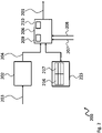
- Fig. 2 shows a block diagram of another of a signal quality sensor 200.
- the signal quality sensor 200 is based on the signal quality sensor 100. Therefore, the signal quality sensor 200 also comprises a bit error detector 202 that is coupled to a quality determination unit 206.
- the above explanations also apply to the bit error detector 202 and the quality determination unit 206.
- a device database 215 is provided in the signal quality sensor 200 .
- the device database 215 stores pairs of operating frequencies 216 and devices 217 capable of emitting RF signals at the respective operating frequencies 216. Therefore, the quality determination unit 206 may determine based on the frequency of the interference signal and the operating frequencies 216 stored in the database which devices 217 emit the interference signals. The quality determination unit 206 may therefore also output information about the devices 217 that emit the interference signals. This may allow to more easily identify the respective devices 217.
- the quality determination unit 206 may calculate the difference between the frequencies of the interference signals and the operating frequencies 216 of the devices 217 that are stored in the device database 215. If the absolute value of the calculated difference is smaller than the bandwidth of the selected channel for an operating frequency 216 the quality determination unit 206 may output information about respective device 217.
- Fig. 3 shows a block diagram of a TV set 350.
- the TV set 350 comprises RF input 352 for receiving the source signal 353.
- the RF input 352 is coupled to an interference detector 354.
- the interference detector 354 provides the source signal 353 to an interference filter 355.
- the interference filter 355 then provides the filtered source signal 353 to the display 351.
- display 351 may include any component or element required to decode or demodulate the source signal 353 and to extract the respective digital channel data to display the channel selected by the user. It is also understood, that such elements may be provided anywhere in the signal chain between RF input 352 and display 351.
- the interference detector 354 is further coupled to a control unit 356.
- the control unit 356 is coupled to the interference filter 355, the display 351 and the quality determination unit 306.
- the quality determination unit 306 provides the control unit 356 with the signal quality 301.
- the signal quality sensor of the TV set 350 is not explicitly referenced. However, the signal quality sensor of the TV set 350 is based on the signal quality sensor 200. Therefore, the signal quality sensor of the TV set 350 comprises a bit error detector 302 that is coupled to a quality determination unit 306. The above explanations also apply to the bit error detector 302 and the quality determination unit 306.
- the signal quality sensor further comprises a device database 315.
- the device database 315 stores pairs of operating frequencies 316 and devices 317 capable of emitting RF signals at the respective operating frequencies 316.
- the signal quality sensor of the TV set 350 comprises a device detection unit 320 that identifies devices 317 present in the vicinity of the signal quality sensor or in the vicinity of the TV set 350 based on a predetermined frequency to device type mapping.
- the device detection unit 320 stores the operating frequencies 316 of the detected devices 317 in the device database 315 together with device type information.
- a user interface 321 is provided that may be used to receive user-provided device information 322 that may then be stored in the device database 315.
- the user-provided device information 322 may comprise operating frequencies 316 and/or device types.
- the interference detector 354 detects levels 307 of interference signals in the source signal 353 in a frequency range of a selected channel.
- the interference filter 355 eliminates interference signals in the source signal 353 based on configurable filter coefficients.
- the configurable filter coefficients may e.g. be set by the control unit 356 based on the detected interference levels.
- the control unit 356 may also provide the signal quality sensor with the detected level 307 of interference signals and the set values 308 of the filter coefficients of the interference filter 355. Further, the control unit 356 receives from the quality determination unit 306 an indication about the signal quality 301.
- control unit 356 If the signal is determined to be insufficient, the control unit 356 outputs the indication on a display 351 of the TV set 350.
- the control unit 356 may especially output in the display 351 an indication of the device 317 that causes the interference signals.
- Fig. 4 shows a flow diagram of an embodiment of a method for determining the signal quality 101, 201, 301 in a TV set 350 with an RF input 352 for receiving a source signal 353 and an interference filter 355.
- the method comprises determining S1 a level 107, 207, 307 of interference signals in the source signal 353, eliminating S2 interference signals in the source signal 353 with an interference filter 355 based on configurable filter coefficients, detecting S3 a bit error rate 104, 204, 304 in a decoded source signal 103, 203, 303 for a selected channel, and determining S4 the signal quality 101, 201, 301 to be insufficient if the filter coefficients are set to a maximum value 109, 209, 309 and the bit error rate 104, 204, 304 is above a predetermined threshold value 110, 210, 310.
- the method may comprise storing operating frequencies 216, 316 for devices 217, 317 capable of emitting RF signals in a device database 215, 315. This allows determining based on the frequency of the interference signal and the operating frequencies 216, 316 stored in the database which devices 217, 317 emit the interference signals.
- the method may also comprise calculating the difference between the frequencies of the interference signals and the operating frequencies 216, 316 of the devices 217, 317 that are stored in the device database 215, 315, and outputting information about respective devices 217, 317 if the absolute value of the calculated difference is smaller than the bandwidth of the selected channel.
- Information about the devices 217, 317 that emit the interference signals may then be output on a display 351 of the TV set 350. This may also include outputting in the display an indication of the specific device 217, 317 that causes the interference signals if the signal quality 101, 201, 301 is indicated to be insufficient.
- Devices 217, 317 may be identified in the vicinity of the signal quality sensor 100, 200 or in the vicinity of the TV set 350 based on a predetermined frequency-to-device-type mapping.
- the operating frequencies 216, 316 of the detected devices 217, 317 may then be stored in the device database 215, 315 together with device type information.
- user-provided device information 322 may be received and stored in the user-provided device information 322 in the device database 215, 315, wherein the user-provided device information 322 comprises operating frequencies 216, 316 and/or device types.
- Fig. 5 shows a flow diagram of another embodiment of a method according to the present invention.
- step S12 the values 108, 208, 308 of the filter coefficients are determined.
- Decision D1 returns to step S12 if the values 108, 208, 308 of the coefficients of the interference filter 355 are lower than respective maximum values 109, 209, 309. If the values 108, 208, 308 of the coefficients of the interference filter 355 are equal to or higher than respective maximum values 109, 209, 309, in decision D2 it is verified if the bit error rate 104, 204, 304 is above a predetermined threshold value 110, 210, 310. If the bit error rate 104, 204, 304 is below the predetermined threshold value 110, 210, 310, the method returns to step S12.
- the specific device 217, 317 is determined that may cause the interference.
- the device 217, 317 may be identified as described above, i.e. with respective formulas.
- the formula may e.g. be B >
- RFDn is the operating frequency of device "n”
- IF is the frequency of the interference signal. This specifically takes into account the measured interference signals and their frequencies.
- the following formula may be used to determine the respective device that causes interference, B >
- RFDn is the operating frequency of device "n”
- RFC is the frequency of the selected channel.
- a respective information is provided to the user in step S13, e.g. via a display 351 of a TV set 350.
- the present invention provides a signal quality sensor 100, 200 for determining the signal quality 101, 201, 301 in a TV set 350 with an RF input 352 for receiving a source signal 353 and an interference filter 355, the signal quality sensor 100, 200 comprising a bit error detector 102, 202, 302 configured to detect a bit error rate 104, 204, 304 in a decoded source signal 103, 203, 303 for the selected channel, a quality determination unit 106, 206, 306 configured to receive a level 107, 207, 307 of interference signals in the source signal 353 and values 108, 208, 308 of filter coefficients of an interference filter 355 for the source signals 353, wherein the quality determination unit 106, 206, 306 is configured to determine the signal quality 101, 201, 301 to be insufficient if the filter coefficients are set to a maximum value 109, 209, 309 and the bit error rate 104, 204, 304 is above a predetermined threshold value 110, 210, 310
- the signal quality sensor 100, 200 comprising a bit error detector 102, 202, 302 configured to detect a bit error rate 104, 204, 304 in a decoded source signal 103, 203, 303 for the selected channel, a quality determination unit 106, 206, 306 configured to receive a level 107, 207, 307 of interference signals in the source signal 353 and values 108, 208, 308 of filter coefficients of an interference filter 355 for the source signals 353, wherein the quality determination unit 106, 206, 306 is configured to determine the signal quality 101, 201, 301 to be insufficient if the filter coefficients are set to a maximum value 109, 209, 309 and the bit error rate 104, 204, 304 is above a predetermined threshold value 110, 210, 310. Further, the present invention provides a respective TV set 350 and a respective method.
Landscapes
- Engineering & Computer Science (AREA)
- Multimedia (AREA)
- Signal Processing (AREA)
- Health & Medical Sciences (AREA)
- Biomedical Technology (AREA)
- General Health & Medical Sciences (AREA)
- Testing, Inspecting, Measuring Of Stereoscopic Televisions And Televisions (AREA)
- Noise Elimination (AREA)
Claims (11)
- Capteur de qualité de signal (100, 200) pour déterminer la qualité du signal (101, 201, 301) dans un téléviseur (350) avec une entrée RF (352) pour recevoir un signal source (353) et un filtre d'interférence (355), le capteur de qualité de signal (100, 200) comprenant :un détecteur d'erreurs binaires (102, 202, 302) configuré pour détecter un taux d'erreurs binaires (104, 204, 304) dans un signal source décodé (103, 203, 303) pour un canal sélectionné,une unité de détermination de qualité (106, 206, 306) configurée pour recevoir un niveau (107, 207, 307) de signaux d'interférence dans le signal source (353) et des valeurs (108, 208, 308) de coefficients de filtre d'un filtre d'interférence (355) pour les signaux source (353), dans laquelle l'unité de détermination de qualité (106, 206, 306) est configurée pour déterminer que la qualité du signal (101, 201, 301) est insuffisante si les coefficients de filtre sont fixés à une valeur maximale (109, 209, 309) et si le taux d'erreur sur les bits (104, 204, 304) est supérieur à une valeur de seuil prédéterminée (110, 210, 310)caractérisé parcomprenant une base de données de dispositifs (215, 315) configurée pour stocker des fréquences de fonctionnement (216, 316) pour des dispositifs (217, 317) capables d'émettre des signaux RF,dans lequel l'unité de détermination de qualité (106, 206, 306) est configurée pour déterminer, sur la base de la fréquence du signal d'interférence et des fréquences de fonctionnement (216, 316) stockées dans la base de données, quels dispositifs (217, 317) émettent les signaux d'interférence, etdans lequel l'unité de détermination de qualité (106, 206, 306) est configurée pour sortir des informations concernant les dispositifs (217, 317) qui émettent les signaux d'interférence sur un affichage (351) du poste de télévision (350).
- Capteur de qualité de signal (100, 200) selon la revendication 1, dans lequel l'unité de détermination de qualité (106, 206, 306) est configurée pour calculer la différence entre les fréquences des signaux d'interférence et les fréquences de fonctionnement (216, 316) des dispositifs (217, 317) qui sont stockées dans la base de données de dispositifs (215, 315) et sortir des informations sur les dispositifs respectifs (217, 317) si la valeur absolue de la différence calculée est inférieure à la largeur de bande du canal sélectionné.
- Capteur de qualité de signal (100, 200) selon l'une quelconque des revendications 1 et 2, comprenant une unité de détection de dispositif (320) configurée pour identifier des dispositifs (217, 317) présents à proximité du capteur de qualité de signal (100, 200) ou à proximité du poste de télévision (350) sur la base d'une mise en correspondance prédéterminée entre fréquence et type de dispositif et pour stocker les fréquences de fonctionnement (216, 316) des dispositifs détectés (217, 317) dans la base de données de dispositifs (215, 315) avec des informations de type de dispositif.
- Capteur de qualité de signal (100, 200) selon l'une quelconque des revendications 1 à 3, comprenant une interface utilisateur (321) configurée pour recevoir des informations de dispositif fournies par l'utilisateur (322) et pour stocker les informations de dispositif fournies par l'utilisateur (322) dans la base de données de dispositif (215, 315),
dans lequel les informations de dispositif fournies par l'utilisateur (322) comprennent des fréquences de fonctionnement (216, 316) et/ou des types de dispositif. - Poste de télévision (350) comprenant :une entrée RF (352) configurée pour recevoir un signal source (353),un détecteur d'interférence (354) configuré pour détecter des niveaux (107, 207, 307) de signaux d'interférence dans le signal source (353) dans une plage de fréquences d'un canal sélectionné,un filtre d'interférence (355) configuré pour éliminer les signaux d'interférence dans le signal source (353) sur la base de coefficients de filtre configurables,une unité de commande (356) configurée pour régler les coefficients de filtre sur la base du niveau détecté (107, 207, 307) des signaux d'interférence, etun capteur de qualité de signal (100, 200) selon l'une quelconque des revendications précédentes,dans lequel l'unité de commande (356) est configurée pour fournir au capteur de qualité de signal (100, 200) le niveau détecté (107, 207, 307) de signaux d'interférence et les valeurs fixées des coefficients de filtre du filtre d'interférence (355), etdans lequel l'unité de commande (356) est configurée pour recevoir de l'unité de détermination de la qualité (106, 206, 306) une indication sur la qualité du signal (101, 201, 301) et émettre l'indication sur un affichage (351) du poste de télévision (350) si la qualité du signal (101, 201, 301) est indiquée comme étant insuffisante.
- Poste de télévision (350) selon la revendication 5, comprenant un capteur de qualité de signal (100, 200) selon l'une quelconque des revendications 3 à 6, dans lequel l'unité de commande (356) est configurée pour sortir sur l'affichage (351) une indication du dispositif (217, 317) qui cause les signaux d'interférence si la qualité du signal (101, 201, 301) est indiquée comme étant insuffisante.
- Méthode pour déterminer la qualité du signal (101, 201, 301) dans un téléviseur (350) avec une entrée RF (352) pour recevoir un signal source (353) et un filtre d'interférence (355), la méthode comprenant :la détermination (S1) d'un niveau (107, 207, 307) de signaux d'interférence dans le signal source (353),éliminer (S2) les signaux d'interférence dans le signal source (353) avec un filtre d'interférence (355) basé sur des coefficients de filtre configurables, etdétecter (S3) un taux d'erreur binaire (104, 204, 304) dans un signal source décodé (103, 203, 303) pour un canal sélectionné,déterminer (S4) que la qualité du signal (101, 201, 301) est insuffisante si les coefficients de filtrage sont réglés sur une valeur maximale (109, 209, 309) et que le taux d'erreurs sur les bits (104, 204, 304) est supérieur à une valeur de seuil prédéterminée (110, 210, 310),caractérisé parcomprenant en outre le stockage de fréquences de fonctionnement (216, 316) pour des dispositifs (217, 317) capables d'émettre des signaux RF dans une base de données de dispositifs (215, 315),déterminer, sur la base de la fréquence du signal d'interférence et des fréquences de fonctionnement (216, 316) stockées dans la base de données, quels dispositifs (217, 317) émettent les signaux d'interférence, et délivrer des informations concernant les dispositifs (217, 317) qui émettent les signaux d'interférence sur un écran (351) du poste de télévision (350).
- Méthode selon la revendication 7, comprenant le calcul de la différence entre les fréquences des signaux d'interférence et les fréquences de fonctionnement (216, 316) des dispositifs (217, 317) qui sont stockées dans la base de données de dispositifs (215, 315), et
délivrer des informations sur les dispositifs respectifs (217, 317) si la valeur absolue de la différence calculée est inférieure à la largeur de bande du canal sélectionné. - Méthode selon la revendication 8, comprenant la sortie sur l'affichage d'une indication du dispositif (217, 317) qui cause les signaux d'interférence si la qualité du signal (101, 201, 301) est indiquée comme étant insuffisante.
- Méthode selon l'une quelconque des revendications 7 à 9, identifiant les dispositifs (217, 317) présents à proximité du capteur de qualité de signal (100, 200) ou à proximité du téléviseur (350) sur la base d'une mise en correspondance prédéterminée entre fréquence et type de dispositif, et
stocker les fréquences de fonctionnement (216, 316) des dispositifs détectés (217, 317) dans la base de données de dispositifs (215, 315) avec des informations de type de dispositif. - Méthode selon l'une quelconque des revendications 7 à 10, comprenant la réception d'informations de dispositif fournies par l'utilisateur (322) et le stockage des informations de dispositif fournies par l'utilisateur (322) dans la base de données de dispositifs (215, 315),
dans lequel les informations de dispositif fournies par l'utilisateur (322) comprennent des fréquences de fonctionnement (216, 316) et/ou des types de dispositif.
Priority Applications (1)
| Application Number | Priority Date | Filing Date | Title |
|---|---|---|---|
| EP19182540.5A EP3758367B1 (fr) | 2019-06-26 | 2019-06-26 | Capteur de qualité de signal, appareil de télévision et procédé pour determiner la qualite du signal de télévision |
Applications Claiming Priority (1)
| Application Number | Priority Date | Filing Date | Title |
|---|---|---|---|
| EP19182540.5A EP3758367B1 (fr) | 2019-06-26 | 2019-06-26 | Capteur de qualité de signal, appareil de télévision et procédé pour determiner la qualite du signal de télévision |
Publications (2)
| Publication Number | Publication Date |
|---|---|
| EP3758367A1 EP3758367A1 (fr) | 2020-12-30 |
| EP3758367B1 true EP3758367B1 (fr) | 2022-11-09 |
Family
ID=67105726
Family Applications (1)
| Application Number | Title | Priority Date | Filing Date |
|---|---|---|---|
| EP19182540.5A Active EP3758367B1 (fr) | 2019-06-26 | 2019-06-26 | Capteur de qualité de signal, appareil de télévision et procédé pour determiner la qualite du signal de télévision |
Country Status (1)
| Country | Link |
|---|---|
| EP (1) | EP3758367B1 (fr) |
Family Cites Families (3)
| Publication number | Priority date | Publication date | Assignee | Title |
|---|---|---|---|---|
| US6201564B1 (en) * | 1997-09-19 | 2001-03-13 | Samsung Electronics Co., Ltd. | Method of operating the channel equalizer in a receiver for DTV signals subject to co-channel NTSC interference |
| US20030065803A1 (en) * | 2001-09-28 | 2003-04-03 | Koninklijke Philips Electronics N. V. | Intelligent delivery method for streamed content |
| JP2008147808A (ja) * | 2006-12-07 | 2008-06-26 | Matsushita Electric Ind Co Ltd | ダイバシティアンテナを用いた高周波信号受信部とこれを用いた高周波信号受信装置 |
-
2019
- 2019-06-26 EP EP19182540.5A patent/EP3758367B1/fr active Active
Also Published As
| Publication number | Publication date |
|---|---|
| EP3758367A1 (fr) | 2020-12-30 |
Similar Documents
| Publication | Publication Date | Title |
|---|---|---|
| CN101849365B (zh) | 使用相关来检测信号的鲁棒的感知 | |
| EP1552629B1 (fr) | Indicateur de l'intensite du signal se propageant par trajets multiples | |
| JP5075212B2 (ja) | マルチパス環境において変調を分類する装置及び方法 | |
| CN101563850B (zh) | 用于确定性地减少信号干扰的技术 | |
| CN101690061A (zh) | 通过使用导频音对ofdm信号的谱感测 | |
| JP2002152613A (ja) | チュナー | |
| CN101371569A (zh) | 使用周期平稳工具箱检测嵌入到噪声中的电视信号的存在 | |
| EP2302854B1 (fr) | Appareil de réception, procédé de réception, programme et système de réception | |
| US20120250807A1 (en) | Schemes for detecting guard intervals in ofdm system | |
| JP2010508757A (ja) | 同一チャネル干渉検出器 | |
| JP5828215B2 (ja) | 受信装置、受信方法、およびプログラム | |
| US6631165B1 (en) | Code modulation using narrow spectral notching | |
| WO2012137657A1 (fr) | Appareil récepteur, procédé de réception et programme associé | |
| EP3758367B1 (fr) | Capteur de qualité de signal, appareil de télévision et procédé pour determiner la qualite du signal de télévision | |
| US8681904B2 (en) | Receiver, reception method, program and reception system | |
| JP2008312027A (ja) | 受信装置及び受信方法 | |
| CN1762121B (zh) | 数字电信的测试设备 | |
| JP5173490B2 (ja) | 感度劣化推定システム及び感度劣化推定方法 | |
| KR102555464B1 (ko) | 전자 장치 및 그 동작 방법 | |
| TR201909474A2 (tr) | Si̇nyal kali̇te sensörü, tv seti̇, yöntem | |
| JP2002344843A (ja) | デジタル放送受信装置 | |
| US9596045B2 (en) | Method for determining impulsive interference applicable to orthogonal frequency division multiple access signal receiver and receiver thereof | |
| US7664186B2 (en) | Channel decoding for multicarrier signal transmission by means of DC-offset and carrier-frequency offset-dependent weighting of reliability information | |
| US8885107B2 (en) | Signal processing device, signal processing method, and program for selectively processing a desired broadcast signal from a plurality of received broadcast signals | |
| EP2587797A1 (fr) | Appareil d'analyse de canal et procédé d'analyse de canal pour co-analyser différents signaux de télévision dans un canal de fréquence radio sélectionné |
Legal Events
| Date | Code | Title | Description |
|---|---|---|---|
| PUAI | Public reference made under article 153(3) epc to a published international application that has entered the european phase |
Free format text: ORIGINAL CODE: 0009012 |
|
| STAA | Information on the status of an ep patent application or granted ep patent |
Free format text: STATUS: THE APPLICATION HAS BEEN PUBLISHED |
|
| AK | Designated contracting states |
Kind code of ref document: A1 Designated state(s): AL AT BE BG CH CY CZ DE DK EE ES FI FR GB GR HR HU IE IS IT LI LT LU LV MC MK MT NL NO PL PT RO RS SE SI SK SM TR |
|
| AX | Request for extension of the european patent |
Extension state: BA ME |
|
| STAA | Information on the status of an ep patent application or granted ep patent |
Free format text: STATUS: REQUEST FOR EXAMINATION WAS MADE |
|
| 17P | Request for examination filed |
Effective date: 20210625 |
|
| RBV | Designated contracting states (corrected) |
Designated state(s): AL AT BE BG CH CY CZ DE DK EE ES FI FR GB GR HR HU IE IS IT LI LT LU LV MC MK MT NL NO PL PT RO RS SE SI SK SM TR |
|
| GRAP | Despatch of communication of intention to grant a patent |
Free format text: ORIGINAL CODE: EPIDOSNIGR1 |
|
| STAA | Information on the status of an ep patent application or granted ep patent |
Free format text: STATUS: GRANT OF PATENT IS INTENDED |
|
| RIC1 | Information provided on ipc code assigned before grant |
Ipc: H04N 17/04 20060101ALI20220430BHEP Ipc: H04N 5/50 20060101ALI20220430BHEP Ipc: H04N 5/44 20110101AFI20220430BHEP |
|
| INTG | Intention to grant announced |
Effective date: 20220531 |
|
| GRAS | Grant fee paid |
Free format text: ORIGINAL CODE: EPIDOSNIGR3 |
|
| GRAA | (expected) grant |
Free format text: ORIGINAL CODE: 0009210 |
|
| STAA | Information on the status of an ep patent application or granted ep patent |
Free format text: STATUS: THE PATENT HAS BEEN GRANTED |
|
| AK | Designated contracting states |
Kind code of ref document: B1 Designated state(s): AL AT BE BG CH CY CZ DE DK EE ES FI FR GB GR HR HU IE IS IT LI LT LU LV MC MK MT NL NO PL PT RO RS SE SI SK SM TR |
|
| REG | Reference to a national code |
Ref country code: GB Ref legal event code: FG4D |
|
| REG | Reference to a national code |
Ref country code: CH Ref legal event code: EP Ref country code: AT Ref legal event code: REF Ref document number: 1531102 Country of ref document: AT Kind code of ref document: T Effective date: 20221115 |
|
| REG | Reference to a national code |
Ref country code: DE Ref legal event code: R096 Ref document number: 602019021620 Country of ref document: DE |
|
| REG | Reference to a national code |
Ref country code: IE Ref legal event code: FG4D |
|
| REG | Reference to a national code |
Ref country code: LT Ref legal event code: MG9D |
|
| REG | Reference to a national code |
Ref country code: NL Ref legal event code: MP Effective date: 20221109 |
|
| REG | Reference to a national code |
Ref country code: AT Ref legal event code: MK05 Ref document number: 1531102 Country of ref document: AT Kind code of ref document: T Effective date: 20221109 |
|
| PG25 | Lapsed in a contracting state [announced via postgrant information from national office to epo] |
Ref country code: SE Free format text: LAPSE BECAUSE OF FAILURE TO SUBMIT A TRANSLATION OF THE DESCRIPTION OR TO PAY THE FEE WITHIN THE PRESCRIBED TIME-LIMIT Effective date: 20221109 Ref country code: PT Free format text: LAPSE BECAUSE OF FAILURE TO SUBMIT A TRANSLATION OF THE DESCRIPTION OR TO PAY THE FEE WITHIN THE PRESCRIBED TIME-LIMIT Effective date: 20230309 Ref country code: NO Free format text: LAPSE BECAUSE OF FAILURE TO SUBMIT A TRANSLATION OF THE DESCRIPTION OR TO PAY THE FEE WITHIN THE PRESCRIBED TIME-LIMIT Effective date: 20230209 Ref country code: LT Free format text: LAPSE BECAUSE OF FAILURE TO SUBMIT A TRANSLATION OF THE DESCRIPTION OR TO PAY THE FEE WITHIN THE PRESCRIBED TIME-LIMIT Effective date: 20221109 Ref country code: FI Free format text: LAPSE BECAUSE OF FAILURE TO SUBMIT A TRANSLATION OF THE DESCRIPTION OR TO PAY THE FEE WITHIN THE PRESCRIBED TIME-LIMIT Effective date: 20221109 Ref country code: ES Free format text: LAPSE BECAUSE OF FAILURE TO SUBMIT A TRANSLATION OF THE DESCRIPTION OR TO PAY THE FEE WITHIN THE PRESCRIBED TIME-LIMIT Effective date: 20221109 Ref country code: AT Free format text: LAPSE BECAUSE OF FAILURE TO SUBMIT A TRANSLATION OF THE DESCRIPTION OR TO PAY THE FEE WITHIN THE PRESCRIBED TIME-LIMIT Effective date: 20221109 |
|
| PG25 | Lapsed in a contracting state [announced via postgrant information from national office to epo] |
Ref country code: RS Free format text: LAPSE BECAUSE OF FAILURE TO SUBMIT A TRANSLATION OF THE DESCRIPTION OR TO PAY THE FEE WITHIN THE PRESCRIBED TIME-LIMIT Effective date: 20221109 Ref country code: PL Free format text: LAPSE BECAUSE OF FAILURE TO SUBMIT A TRANSLATION OF THE DESCRIPTION OR TO PAY THE FEE WITHIN THE PRESCRIBED TIME-LIMIT Effective date: 20221109 Ref country code: LV Free format text: LAPSE BECAUSE OF FAILURE TO SUBMIT A TRANSLATION OF THE DESCRIPTION OR TO PAY THE FEE WITHIN THE PRESCRIBED TIME-LIMIT Effective date: 20221109 Ref country code: IS Free format text: LAPSE BECAUSE OF FAILURE TO SUBMIT A TRANSLATION OF THE DESCRIPTION OR TO PAY THE FEE WITHIN THE PRESCRIBED TIME-LIMIT Effective date: 20230309 Ref country code: HR Free format text: LAPSE BECAUSE OF FAILURE TO SUBMIT A TRANSLATION OF THE DESCRIPTION OR TO PAY THE FEE WITHIN THE PRESCRIBED TIME-LIMIT Effective date: 20221109 Ref country code: GR Free format text: LAPSE BECAUSE OF FAILURE TO SUBMIT A TRANSLATION OF THE DESCRIPTION OR TO PAY THE FEE WITHIN THE PRESCRIBED TIME-LIMIT Effective date: 20230210 |
|
| PG25 | Lapsed in a contracting state [announced via postgrant information from national office to epo] |
Ref country code: NL Free format text: LAPSE BECAUSE OF FAILURE TO SUBMIT A TRANSLATION OF THE DESCRIPTION OR TO PAY THE FEE WITHIN THE PRESCRIBED TIME-LIMIT Effective date: 20221109 |
|
| PG25 | Lapsed in a contracting state [announced via postgrant information from national office to epo] |
Ref country code: SM Free format text: LAPSE BECAUSE OF FAILURE TO SUBMIT A TRANSLATION OF THE DESCRIPTION OR TO PAY THE FEE WITHIN THE PRESCRIBED TIME-LIMIT Effective date: 20221109 Ref country code: RO Free format text: LAPSE BECAUSE OF FAILURE TO SUBMIT A TRANSLATION OF THE DESCRIPTION OR TO PAY THE FEE WITHIN THE PRESCRIBED TIME-LIMIT Effective date: 20221109 Ref country code: EE Free format text: LAPSE BECAUSE OF FAILURE TO SUBMIT A TRANSLATION OF THE DESCRIPTION OR TO PAY THE FEE WITHIN THE PRESCRIBED TIME-LIMIT Effective date: 20221109 Ref country code: DK Free format text: LAPSE BECAUSE OF FAILURE TO SUBMIT A TRANSLATION OF THE DESCRIPTION OR TO PAY THE FEE WITHIN THE PRESCRIBED TIME-LIMIT Effective date: 20221109 Ref country code: CZ Free format text: LAPSE BECAUSE OF FAILURE TO SUBMIT A TRANSLATION OF THE DESCRIPTION OR TO PAY THE FEE WITHIN THE PRESCRIBED TIME-LIMIT Effective date: 20221109 |
|
| REG | Reference to a national code |
Ref country code: DE Ref legal event code: R097 Ref document number: 602019021620 Country of ref document: DE |
|
| PG25 | Lapsed in a contracting state [announced via postgrant information from national office to epo] |
Ref country code: SK Free format text: LAPSE BECAUSE OF FAILURE TO SUBMIT A TRANSLATION OF THE DESCRIPTION OR TO PAY THE FEE WITHIN THE PRESCRIBED TIME-LIMIT Effective date: 20221109 Ref country code: AL Free format text: LAPSE BECAUSE OF FAILURE TO SUBMIT A TRANSLATION OF THE DESCRIPTION OR TO PAY THE FEE WITHIN THE PRESCRIBED TIME-LIMIT Effective date: 20221109 |
|
| PLBE | No opposition filed within time limit |
Free format text: ORIGINAL CODE: 0009261 |
|
| STAA | Information on the status of an ep patent application or granted ep patent |
Free format text: STATUS: NO OPPOSITION FILED WITHIN TIME LIMIT |
|
| 26N | No opposition filed |
Effective date: 20230810 |
|
| PGFP | Annual fee paid to national office [announced via postgrant information from national office to epo] |
Ref country code: GB Payment date: 20230920 Year of fee payment: 5 |
|
| PG25 | Lapsed in a contracting state [announced via postgrant information from national office to epo] |
Ref country code: SI Free format text: LAPSE BECAUSE OF FAILURE TO SUBMIT A TRANSLATION OF THE DESCRIPTION OR TO PAY THE FEE WITHIN THE PRESCRIBED TIME-LIMIT Effective date: 20221109 |
|
| PGFP | Annual fee paid to national office [announced via postgrant information from national office to epo] |
Ref country code: DE Payment date: 20230920 Year of fee payment: 5 |
|
| PG25 | Lapsed in a contracting state [announced via postgrant information from national office to epo] |
Ref country code: MC Free format text: LAPSE BECAUSE OF FAILURE TO SUBMIT A TRANSLATION OF THE DESCRIPTION OR TO PAY THE FEE WITHIN THE PRESCRIBED TIME-LIMIT Effective date: 20221109 |
|
| PG25 | Lapsed in a contracting state [announced via postgrant information from national office to epo] |
Ref country code: MC Free format text: LAPSE BECAUSE OF FAILURE TO SUBMIT A TRANSLATION OF THE DESCRIPTION OR TO PAY THE FEE WITHIN THE PRESCRIBED TIME-LIMIT Effective date: 20221109 |
|
| REG | Reference to a national code |
Ref country code: CH Ref legal event code: PL |
|
| REG | Reference to a national code |
Ref country code: BE Ref legal event code: MM Effective date: 20230630 |
|
| PG25 | Lapsed in a contracting state [announced via postgrant information from national office to epo] |
Ref country code: LU Free format text: LAPSE BECAUSE OF NON-PAYMENT OF DUE FEES Effective date: 20230626 |
|
| REG | Reference to a national code |
Ref country code: IE Ref legal event code: MM4A |
|
| PG25 | Lapsed in a contracting state [announced via postgrant information from national office to epo] |
Ref country code: LU Free format text: LAPSE BECAUSE OF NON-PAYMENT OF DUE FEES Effective date: 20230626 |
|
| PG25 | Lapsed in a contracting state [announced via postgrant information from national office to epo] |
Ref country code: IE Free format text: LAPSE BECAUSE OF NON-PAYMENT OF DUE FEES Effective date: 20230626 |
|
| PG25 | Lapsed in a contracting state [announced via postgrant information from national office to epo] |
Ref country code: IE Free format text: LAPSE BECAUSE OF NON-PAYMENT OF DUE FEES Effective date: 20230626 Ref country code: CH Free format text: LAPSE BECAUSE OF NON-PAYMENT OF DUE FEES Effective date: 20230630 |
|
| PG25 | Lapsed in a contracting state [announced via postgrant information from national office to epo] |
Ref country code: IT Free format text: LAPSE BECAUSE OF FAILURE TO SUBMIT A TRANSLATION OF THE DESCRIPTION OR TO PAY THE FEE WITHIN THE PRESCRIBED TIME-LIMIT Effective date: 20221109 Ref country code: FR Free format text: LAPSE BECAUSE OF NON-PAYMENT OF DUE FEES Effective date: 20230630 Ref country code: BE Free format text: LAPSE BECAUSE OF NON-PAYMENT OF DUE FEES Effective date: 20230630 |
|
| PG25 | Lapsed in a contracting state [announced via postgrant information from national office to epo] |
Ref country code: BG Free format text: LAPSE BECAUSE OF FAILURE TO SUBMIT A TRANSLATION OF THE DESCRIPTION OR TO PAY THE FEE WITHIN THE PRESCRIBED TIME-LIMIT Effective date: 20221109 |
|
| PG25 | Lapsed in a contracting state [announced via postgrant information from national office to epo] |
Ref country code: BG Free format text: LAPSE BECAUSE OF FAILURE TO SUBMIT A TRANSLATION OF THE DESCRIPTION OR TO PAY THE FEE WITHIN THE PRESCRIBED TIME-LIMIT Effective date: 20221109 |
|
| REG | Reference to a national code |
Ref country code: DE Ref legal event code: R119 Ref document number: 602019021620 Country of ref document: DE |
|
| GBPC | Gb: european patent ceased through non-payment of renewal fee |
Effective date: 20240626 |
|
| PG25 | Lapsed in a contracting state [announced via postgrant information from national office to epo] |
Ref country code: DE Free format text: LAPSE BECAUSE OF NON-PAYMENT OF DUE FEES Effective date: 20250101 |
|
| PG25 | Lapsed in a contracting state [announced via postgrant information from national office to epo] |
Ref country code: GB Free format text: LAPSE BECAUSE OF NON-PAYMENT OF DUE FEES Effective date: 20240626 |
|
| PG25 | Lapsed in a contracting state [announced via postgrant information from national office to epo] |
Ref country code: CY Free format text: LAPSE BECAUSE OF FAILURE TO SUBMIT A TRANSLATION OF THE DESCRIPTION OR TO PAY THE FEE WITHIN THE PRESCRIBED TIME-LIMIT; INVALID AB INITIO Effective date: 20190626 |
|
| PGFP | Annual fee paid to national office [announced via postgrant information from national office to epo] |
Ref country code: TR Payment date: 20250625 Year of fee payment: 7 |
|
| PG25 | Lapsed in a contracting state [announced via postgrant information from national office to epo] |
Ref country code: HU Free format text: LAPSE BECAUSE OF FAILURE TO SUBMIT A TRANSLATION OF THE DESCRIPTION OR TO PAY THE FEE WITHIN THE PRESCRIBED TIME-LIMIT; INVALID AB INITIO Effective date: 20190626 |