EP3757679A1 - Heizvorrichtung, fixiervorrichtung und bilderzeugungsvorrichtung - Google Patents
Heizvorrichtung, fixiervorrichtung und bilderzeugungsvorrichtung Download PDFInfo
- Publication number
- EP3757679A1 EP3757679A1 EP20177951.9A EP20177951A EP3757679A1 EP 3757679 A1 EP3757679 A1 EP 3757679A1 EP 20177951 A EP20177951 A EP 20177951A EP 3757679 A1 EP3757679 A1 EP 3757679A1
- Authority
- EP
- European Patent Office
- Prior art keywords
- temperature sensor
- temperature
- rotating member
- nip
- fixing belt
- Prior art date
- Legal status (The legal status is an assumption and is not a legal conclusion. Google has not performed a legal analysis and makes no representation as to the accuracy of the status listed.)
- Granted
Links
Images


Classifications
-
- G—PHYSICS
- G03—PHOTOGRAPHY; CINEMATOGRAPHY; ANALOGOUS TECHNIQUES USING WAVES OTHER THAN OPTICAL WAVES; ELECTROGRAPHY; HOLOGRAPHY
- G03G—ELECTROGRAPHY; ELECTROPHOTOGRAPHY; MAGNETOGRAPHY
- G03G15/00—Apparatus for electrographic processes using a charge pattern
- G03G15/20—Apparatus for electrographic processes using a charge pattern for fixing, e.g. by using heat
- G03G15/2003—Apparatus for electrographic processes using a charge pattern for fixing, e.g. by using heat using heat
- G03G15/2014—Apparatus for electrographic processes using a charge pattern for fixing, e.g. by using heat using heat using contact heat
- G03G15/2053—Structural details of heat elements, e.g. structure of roller or belt, eddy current, induction heating
-
- G—PHYSICS
- G03—PHOTOGRAPHY; CINEMATOGRAPHY; ANALOGOUS TECHNIQUES USING WAVES OTHER THAN OPTICAL WAVES; ELECTROGRAPHY; HOLOGRAPHY
- G03G—ELECTROGRAPHY; ELECTROPHOTOGRAPHY; MAGNETOGRAPHY
- G03G15/00—Apparatus for electrographic processes using a charge pattern
- G03G15/20—Apparatus for electrographic processes using a charge pattern for fixing, e.g. by using heat
- G03G15/2003—Apparatus for electrographic processes using a charge pattern for fixing, e.g. by using heat using heat
- G03G15/2014—Apparatus for electrographic processes using a charge pattern for fixing, e.g. by using heat using heat using contact heat
- G03G15/2039—Apparatus for electrographic processes using a charge pattern for fixing, e.g. by using heat using heat using contact heat with means for controlling the fixing temperature
-
- G—PHYSICS
- G03—PHOTOGRAPHY; CINEMATOGRAPHY; ANALOGOUS TECHNIQUES USING WAVES OTHER THAN OPTICAL WAVES; ELECTROGRAPHY; HOLOGRAPHY
- G03G—ELECTROGRAPHY; ELECTROPHOTOGRAPHY; MAGNETOGRAPHY
- G03G15/00—Apparatus for electrographic processes using a charge pattern
- G03G15/50—Machine control of apparatus for electrographic processes using a charge pattern, e.g. regulating differents parts of the machine, multimode copiers, microprocessor control
- G03G15/5004—Power supply control, e.g. power-saving mode, automatic power turn-off
-
- G—PHYSICS
- G03—PHOTOGRAPHY; CINEMATOGRAPHY; ANALOGOUS TECHNIQUES USING WAVES OTHER THAN OPTICAL WAVES; ELECTROGRAPHY; HOLOGRAPHY
- G03G—ELECTROGRAPHY; ELECTROPHOTOGRAPHY; MAGNETOGRAPHY
- G03G2215/00—Apparatus for electrophotographic processes
- G03G2215/20—Details of the fixing device or porcess
- G03G2215/2003—Structural features of the fixing device
- G03G2215/2016—Heating belt
- G03G2215/2035—Heating belt the fixing nip having a stationary belt support member opposing a pressure member
Definitions
- Embodiments of the present disclosure generally relate to a heating device, a fixing device, and an image forming apparatus.
- JP-6164014-B JP-2015-069094-A discloses the fixing device including a fixing belt as a fixing member, a nip formation member to form a fixing nip, and a heater that is disposed inside a loop of the fixing belt and radiates radiant heat to heat the fixing belt and the nip formation member.
- the fixing device including the heater disposed inside the loop of the fixing belt adopts a reflector structure including a reflector having high reflectance and covering around the heater to reflect infrared rays that are not directly emitted from the heater to an object to be heated and irradiate the object to be heated with all infrared rays radially radiated from the heater.
- the object of the present disclosure is improving the temperature control performance of a rotating member such as a fixing belt and preventing a fixing failure caused by a temperature drop in a fixing nip.
- a heating device according to claim 1.
- the heating device includes a rotating member having an endless form, a heater disposed inside a loop of the rotating member, a pressing member disposed opposite the rotating member, a nip formation member, a first temperature sensor, and a second temperature sensor.
- the nip formation member contacts an inner circumferential surface of the rotating member to form a nip between the pressing member and the rotating member.
- the first temperature sensor is configured to detect a temperature of the nip formation member
- the second temperature sensor is configured to detect a temperature of the rotating member.
- the temperature control performance of a rotating member is improved, and a fixing failure caused by a temperature drop in the nip is prevented.
- the image forming apparatus can be a copier, a facsimile machine, a printer, a plotter, and a multifunction peripheral having at least two of copying, printing, facsimile transmission, plotting, and scanning capabilities; or an inkjet recording apparatus.
- a “sheet medium” as a recording medium is described as a “sheet” in the following embodiments, the “sheet medium” is not limited to the sheet made of paper.
- the “sheet” include not only the sheet but also an overhead projector (OHP) transparency, a fabric, a metallic sheet, a plastic film, and a prepreg sheet including carbon fibers previously impregnated with resin.
- OHP overhead projector
- Examples of the "sheet medium” include all media to which developer or ink can adhere, and so-called recording paper and recording sheets.
- Examples of the "sheet” include thick paper, a postcard, an envelope, thin paper, coated paper (e.g., coat paper and art paper), and tracing paper, in addition to plain paper.
- image forming means not only giving an image having a meaning, such as a character or a figure, to a medium but also giving an arbitrary image having no meaning, such as a pattern, to a medium.
- FIG. 1 is a schematic view of a laser printer as an example of an image forming apparatus 100 including a fixing device 300 according to an embodiment of the present disclosure.
- the image forming apparatus 100 includes an image bearer 2 such as a photoconductor drum and a photoconductor cleaner 3.
- the image forming apparatus 100 further includes a charging device 4 as a charger that uniformly charges the surface of the image bearer, a developing device 5 that renders visible an electrostatic latent image on the image bearer, a transfer device TM disposed under the image bearer 2, a discharger, and the like.
- An exposure device 7 as an image forming device is disposed above the image bearer 2.
- the exposure device 7 performs writing and scanning based on image data, that is to say, irradiates the image bearer 2 with laser light Lb emitted by a laser diode based on image data and reflected by a mirror 7a to form an electrostatic latent image on the image bearer 2.
- a sheet feeder 50 including a tray loaded with sheets P is disposed in a lower portion of the image forming apparatus 100.
- the sheet feeder 50 is configured as a recording-medium supply device and can house a sheaf of many sheets P as recording media.
- the sheet feeder 50 is configured as one unit together with a sheet feeding roller 60 as a conveyor for the sheets P.
- a registration roller pair 250 Downstream from the sheet feeding roller 60 in a sheet conveyance direction, a registration roller pair 250 as a separation and conveyance means is disposed.
- the registration roller pair 250 temporarily stops the sheet P fed from the sheet feeder 50. Temporarily stopping the sheet P causes slack on the leading-edge side of the sheet P and corrects a skew of the sheet P.
- the registration roller pair 250 sends the sheet P that contacts the registration roller pair 250 and has the slack on the leading-edge side of the sheet P toward a transfer nip N of the transfer device TM at a timing to suitably transfer a toner image on the image bearer 2 onto the sheet P.
- a bias applied at the transfer nip N electrostatically transfers the toner image formed on the image bearer 2 onto the sent sheet P at a desired transfer position.
- the fixing device 300 is disposed downstream from the transfer nip N in the sheet conveyance direction.
- the fixing device 300 includes a fixing belt 310 as a rotating member, a halogen heater 361 as a heater inside a loop of the fixing belt 310, which is described later, and a pressure roller 320 as a pressing member that rotates while contacting the fixing belt 310 at a predetermined pressure.
- the sheet feeding roller 60 rotates in response to a sheet feeding signal from a controller of the image forming apparatus 100.
- the sheet feeding roller 60 rotates to separate the uppermost sheet from a sheaf of sheets P loaded in the sheet feeder 50 and send the uppermost sheet out to a sheet feeding path.
- the sheet P forms slack and temporarily stops.
- the registration roller pair 250 corrects the front-end skew of the sheet P and rotates in synchronization with an optimum timing to transfer a toner image on the image bearer 2 onto the sheet P.
- the charging device 4 uniformly charges the surface of the image bearer 2 to high potential.
- the exposure device 7 irradiates the surface of the image bearer 2 with the laser light Lb based on the image data and reflected by the mirror 7a.
- the surface of the image bearer 2 irradiated with the laser light Lb has the electrostatic latent image due to a drop in the potential of the irradiated portion.
- the developing device 5 includes a developer bearer 5a bearing a developer including toner and transfers unused black toner supplied from a toner bottle to the surface portion of the image bearer 2 having the electrostatic latent image, through the developer bearer 5a.
- the image bearer 2 to which the toner has been transferred forms (develops) a toner image on the surface of the image bearer 2.
- the transfer device TM transfers the toner image formed on the image bearer 2 onto the sheet P.
- a cleaning blade 3a in the photoconductor cleaner 3 removes the residual toner adhering to the surface of the image bearer 2 after a transfer process.
- the removed residual toner is collected to a waste toner container.
- the sheet P bearing the toner image is conveyed to the fixing device 300.
- the sheet P conveyed to the fixing device 300 is sandwiched by the fixing belt 310 and the pressure roller 320. Then, heating and pressing fixes the unfixed toner image onto the sheet P.
- the sheet P fixed the toner image is sent out from the fixing device 300.
- the fixing device 300 is an embodiment of a heating device according to the present disclosure.
- the heating device according to the present disclosure is also applicable to a dryer to dry ink applied to the sheet in an inkjet type image forming apparatus and a coating device (a laminator) that heats, under pressure, a film serving as a covering member onto the surface of the sheet such as paper conveyed by a belt.
- a coating device a laminator
- the fixing device 300 includes a thin fixing belt 310 having a low thermal capacity and a pressure roller 320.
- the fixing device 300 includes a first temperature sensor 381 as a first temperature detector, a second temperature sensor 382 as a second temperature detector, and a third temperature sensor 383 as a third temperature detector, as described in detail later.
- the first temperature sensor 381 detects a temperature TN of a nip formation member
- the second temperature sensor 382 detects a temperature of the fixing belt 310 inside a range of a sheet conveyance span in the longitudinal direction of the fixing belt 310
- the third temperature sensor 383 detects a temperature of the fixing belt 310 outside the range of the sheet conveyance span, that is a non-sheet conveyance span in the longitudinal direction of the fixing belt 310.
- the fixing belt 310 includes, for example, a tubular base made of polyimide (PI), the tubular base having an outer diameter of 25 mm and a thickness of from 40 to 120 ⁇ m.
- the fixing belt 310 further includes a release layer serving as an outermost surface layer.
- the release layer is made of fluororesin, such as tetrafluoroethylene-perfluoroalkylvinylether copolymer (PFA) and polytetrafluoroethylene (PTFE), and has a thickness of from 5 ⁇ m to 50 ⁇ m to enhance durability of the fixing belt 310 and facilitate separation of the sheet P from the fixing belt 310.
- An elastic layer made of rubber having a thickness of from 50 to 500 ⁇ m may be provided between the base and the release layer.
- the base of the fixing belt 310 may be made of heat-resistant resin such as polyetheretherketone (PEEK) or metal such as nickel (Ni) or stainless steel (Stainless Used Steel, SUS), instead of polyimide.
- PEEK polyetheretherketone
- Ni nickel
- SUS stainless steel
- the inner circumferential surface of the fixing belt 310 may be coated with polyimide or polytetrafluoroethylene (PTFE) as a slide layer.
- PTFE polytetrafluoroethylene
- the pressure roller 320 having, for example, an outer diameter of 25 mm, includes a solid iron cored bar 321, an elastic layer 322 on the surface of the cored bar 321, and a release layer 323 formed on the outside of the elastic layer 322.
- the elastic layer 322 is made of silicone rubber and has a thickness of 3.5 mm, for example.
- the release layer 323 is formed by a fluororesin layer having, for example, a thickness of approximately 40 ⁇ m on the surface of the elastic layer 322 to improve releasability.
- the pressure roller 320 is pressed against the fixing belt 310 by a biasing member.
- the stays 330 as support members and the nip formation member 380 extend axially inside the loop of the fixing belt 310.
- the stays 330 are a pair of metallic members that are made of stainless steel or the like, extend in parallel, face each other, and each have an I-shaped cross-section. Both side plates of the fixing device 300 support both end portions of the stays 330.
- the pair of stays 330 reliably receive the pressing force of the pressure roller 320 acting on the nip formation member 380 and stably form a nip SN having a uniform width over an axial direction of the pressure roller 320 that is a longitudinal direction of the pressure roller 320.
- a plurality of types of sheets having different widths in the axial direction of the fixing belt 310 can pass through the nip SN.
- a stay as a support member may be one unit formed by connecting end portions of the pair of metallic members.
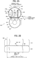
- the nip formation member 380 is a plate bridged between the pair of stays 330 and supported by the stays 330. Both end portions of the nip formation member 380 in the sheet conveyance direction are each bent in an L shape, and the L-shaped bent portions 380a and 380b are located upstream and downstream in the sheet conveyance direction with respect to the pair of stays 330.
- the bent portion located upstream in the sheet conveyance direction is the bent portion 380b on the right side in FIG. 2A
- the bent portion located downstream in the sheet conveyance direction is the bent portion 380a on the left side in FIG. 2A .
- the first temperature sensor 381, which is described later, is sandwiched between the bent portion 380a located downstream in the sheet conveyance direction and the lower end portion of the stay 330.
- the nip formation member 380 transfers heat in an axial direction that is a lateral direction in FIG. 2B in a short time to uniformize temperature of the fixing belt 310 in a width direction of the fixing belt 310.
- the nip formation member 380 is made of a thin plate having high thermal conductivity such as copper (398 W / mK), aluminum (236 W / mK) or silver to smoothly transfer the heat in the width direction. In consideration of cost, processing, and the like, the nip formation member 380 is preferably made of a thin copper plate.
- the inner circumferential surface of the fixing belt 310 slides over the bottom surface of the nip formation member 380 that is a nip formation surface.
- the nip formation surface may be treated with alumite or coated with fluororesin material. Additionally, a lubricant such as fluorine grease may be applied to the nip formation surface to ensure slidability over time.
- the nip formation surface of the nip formation member 380 is planar.
- the nip formation surface may define a recess or other shape.
- a recessed nip formation surface directs a leading edge of the sheet P toward the pressure roller 320 as the sheet is ejected from the fixing nip SN, thereby facilitating separation of the sheet P from the fixing belt 310 and preventing a sheet jam.
- a separator may be disposed downstream from the fixing device 300 in the sheet conveyance direction to separate the sheet P from the fixing belt 310.
- a pressurization assembly may be disposed to press the pressure roller 320 against the fixing belt 310 and release pressure exerted by the pressure roller 320 to the fixing belt 310.
- each reflector 370 is assembled to each of facing surfaces of the pair of stays 330.
- the halogen heater 361 as the heater is arranged at a center position between the right reflector 370 and the left reflector 370 and extends in the axial direction of the fixing belt 310.
- Each of the reflectors 370 is made of a stainless steel plate or the like. Both end portions of the reflector 370, that is, an upper end portion 370a and a lower end portion 370b are bent toward outside and engaged with an upper end portion and a lower end portion of each of the pair of stays 330.
- the reflector 370 is configured to increase heating efficiency for the fixing belt 310 and the nip formation member 380 and to reduce wasteful energy consumption caused by heating the stay 330 with radiant heat from the halogen heater 361.
- the surface of the reflector 370 facing the halogen heater 361 is treated with mirror finish or the like to increase reflectance.
- reflectance is measured using the spectrophotometer that is the ultraviolet visible infrared spectrophotometer UH4150 manufactured by Hitachi High-Tech Science Corporation in which the incident angle is set 5°.
- the color temperature of the halogen heater varies depending on the application.
- the color temperature of the heater for the fixing device is about 2500 K.
- the reflectance of the reflector 370 used in the present embodiment is preferably 70% or more with wavelengths of high emission intensity in the halogen heater 361, that is, specifically the wavelengths of 900 to 1600 nm and more preferably 70% or more with the wavelengths of 1000 to 1300 nm.
- a heater-side face of the stay 330 disposed opposite the halogen heater 361 may be insulated or given a mirror finish to obtain the same effects.
- the reflectance of the stay 330 subjected to the mirror finishing is preferably similar to the reflectance of the reflector 370.
- Both side plates of the fixing device 300 support both ends of the halogen heater 361.
- the above-described fixing device 300 uses one halogen heater 361.
- the fixing device may use a plurality of halogen heaters 361 that are arranged in parallel and have different light emitting sections corresponding to a number of widths of sheets passing through the nip SN. Selecting the plurality of halogen heaters 361 in accordance with the width of the sheet and turning on the selected halogen heater 361 can effectively prevent overheating the non-sheet conveyance span of the fixing belt 310.
- a center portion of the reflector 370 in a vertical direction is away from one of the pair of stays 330 and bulges inwardly in a curved convex shape toward the halogen heater 361.
- This curved inward convex surface of the reflector 370 reflects infrared rays radiated in the left-right direction from the halogen heater 361 upward.
- a radiant light receiving surface of the fixing belt 310 is irradiated with the infrared rays reflected upward by the reflector 370.
- the radiant light receiving surface of the fixing belt 310 located above the halogen heater 361 is directly irradiated with the infrared rays radiated upward from the halogen heater 361.
- infrared rays are mainly described as radiant light, but all light emitted from the halogen heater 361 as a heater is equivalent to radiant light.
- the inner surface of the nip formation member 380 located under the halogen heater 361 is directly irradiated with the infrared rays radiated downward from the halogen heater 361.
- the reflector 370 reflects infrared rays radiated in the left-right direction and an oblique downward direction from the halogen heater 361 toward the oblique downward direction.
- the reflector 370 irradiates the inner surface of the nip formation member 380 with the infrared rays reflected toward the oblique downward direction.
- an upper portion of the fixing belt 310 and the nip formation member 380 under the halogen heater 361 are directly irradiated with the infrared rays radiated around the halogen heater 361. Additionally, the fixing belt 310 and the nip formation member 380 are also efficiently irradiated with the infrared rays reflected by the reflector 370, and the fixing belt 310 at the nip SN is efficiently heated to a target temperature Tc.
- the reflector 370 and the stay 330 in the present embodiment open toward the nip formation member 380.
- the above-described configuration can give a first heat transfer path and a second heat transfer path.
- the halogen heater 361 directly irradiates the nip formation member 380 with the radiant light and indirectly heats the fixing belt 310 via the nip formation member 380.
- the halogen heater 361 directly irradiates and heats the fixing belt 310 with the radiant light.
- a structure of a conventional reflector around the halogen heater is generally an inverted U-shaped reflector structure that covers upper portion of the halogen heater.
- the upper portion of the halogen heater 361 is opened, and each of the fixing belt 310 and the nip formation member 380 is irradiated with the infrared rays radiated from the halogen heater 361 and the infrared rays reflected by the left and right reflectors 370.
- a configuration of the present embodiment as illustrated in FIG. 2A including the nip formation member 380 and the fixing belt 310 which are separately irradiated with the infrared rays and a controller 400 which controls temperatures of the nip formation member 380 and the fixing belt 310 based on values detected by the first temperature sensor 381 and the second temperature sensor 382 has a better performance of temperature control about the fixing belt 310 and more advantageous in reduction of wasteful power consumption, which is described below, than a conventional configuration in which the halogen heater 361 concentratively irradiates the nip formation member with the infrared rays of the halogen heater 361.
- the present embodiment can give an advantage, that is, improvement of the heat transfer efficiency with respect to the fixing belt 310 and the nip formation member 380. Additionally, the controller 400 described below improves the performance of the temperature control of the fixing belt 310 and reduces the fixing failure due to the temperature drop in the nip and unnecessary power consumption.
- the controller 400 controls an amount of alternating current (AC) power supplied to the halogen heater 361 by, for example, phase control.
- the controller 400 is arranged outside the fixing device 300 which is one embodiment of the heating device, for example, inside the controller of the image forming apparatus 100.
- the controller 400 may also configured as a dedicated product of the fixing device 300 independent of the controller of the image forming apparatus 100.
- the first temperature sensor 381 detects a temperature TN of the nip formation member 380.
- a contact position between the first temperature sensor 381 and the nip formation member 380 is disposed outside the nip SN and downstream from the nip SN in the sheet conveyance direction.
- the second temperature sensor 382 is arranged upstream from the radiant light receiving surface in the rotation direction of the fixing belt 310 to face the outer circumferential surface of the fixing belt 310. That is, the second temperature sensor 382 is arranged to face the halogen heater 361 via the stay 330 and the reflector 370 and detect the temperature of the outer circumferential surface or the inner circumferential surface of the fixing belt 310, that is, a fixing belt temperature TB.
- Both the first temperature sensor 381 and the second temperature sensor 382 are disposed at the substantially center position in the axial direction (longitudinal direction) of the fixing belt 310 in the present embodiment but may be disposed in a range corresponding to a sheet conveyance span of the sheet having the smallest width in the axial direction of the fixing belt 310 and downstream from the nip SN in the rotation direction of the fixing belt 310.
- the second temperature sensor 382 is disposed opposite the outer circumferential surface of the fixing belt 310 and downstream from the first temperature sensor 381 in the rotation direction of the fixing belt 310. Both the first temperature sensor 381 and the second temperature sensor 382 are disposed such that a position at which the first temperature sensor 381 detects the temperature of the nip formation member 380 and a position at which the second temperature sensor 382 detects the fixing belt temperature are close to each other in the circumferential direction of the fixing belt 310.
- controller 400 is described.
- the controller 400 in FIG. 4 controls power supplied to the halogen heater 361 by, for example, a proportional integral derivation (PID) control method so that the fixing belt temperature TB changes in the vicinity of a control target temperature Tc determined according to the machine state.
- PID control method is a kind of feedback control method and control of an input value based on three factors, that is, a deviation between an output value and a target value, the integral, and the differential.
- the second temperature sensor 382 detects the fixing belt temperature TB at a position closer to an outlet of the nip SN than the radiant light receiving surface, and the controller 400 calculates a difference between the fixing belt temperature TB and the nip formation member temperature TN, that is, (TN - TB) to compare the fixing belt temperature TB with the nip formation member temperature TN. Based on the difference (TN - TB), the controller 400 can accurately estimate an amount of heat that transfers from the nip formation member 380 to the fixing belt 310 in the nip SN and, based on the estimation, determine the amount of power to be supplied to the halogen heater 361.
- the first temperature sensor 381 and the second temperature sensor 382 are arranged in an outlet side of the nip SN, that is, upstream in the rotation direction of the fixing belt 310 from an upstream end of the radiant light receiving surface.
- a distance D (mm) from the upstream end of the radiant light receiving surface to each of the first temperature sensor 381 and the second temperature sensor 382 is equal to or larger than a product of a control cycle S (seconds) of the halogen heater 361 and a rotation speed V (mm / second) of the fixing belt, that is, (S ⁇ V ⁇ D).
- the above-described configuration enables the controller 400 to immediately determine a control parameter of the halogen heater 361, that is, a parameter of an amount of heat supplied to the fixing belt 310 and the nip formation member 380 at a next timing based on the detected fixing belt temperature TB.
- both the first temperature sensor 381 and the second temperature sensor 382 are arranged in the above-described range (S ⁇ V ⁇ D), but arranging at least one of the first temperature sensor 381 and the second temperature sensor 382 in the above-described range can provide the effect to some extent. That is, arranging at least one of the first temperature sensor 381 and the second temperature sensor 382 in the above-described range enables the controller 400 to immediately determine the parameter of an amount of heat supplied to the fixing belt 310 and the nip formation member 380 at a next timing based on the detected fixing belt temperature TB to some extent.
- both the first temperature sensor 381 and the second temperature sensor 382 at positions close to the outlet of the nip SN enables accurate detection of the temperature difference between the fixing belt 310 and the nip formation member 380 at the nip SN, that is, (TN - TB) and accurate detection of the amount of heat transfer between the fixing belt 310 and the nip formation member 380.
- the controller 400 can accurately determine the power to be supplied to the halogen heater 361. That is, correction of the power supplied to the halogen heater 361 based on the determined power enables accurately keeping the fixing belt temperature TB in the vicinity of the control target temperature Tc, improving fixing property, and reducing the unnecessary power consumption.
- the first temperature sensor 381 and the second temperature sensor 382 are arranged inside the range corresponding to the sheet conveyance span of the sheet having the smallest width, which is used in the image forming apparatus 100, in the axial direction of the fixing belt 310.
- the controller 400 can accurately estimate the necessary power because temperature rise that occurs outside the sheet conveyance span when small size sheets pass through the fixing device does not affect the temperatures detected by the first temperature sensor 381 and the second temperature sensor 382.
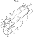
- arranging the first temperature sensor 381 and the second temperature sensor 382 inside the range corresponding to the sheet conveyance span of the sheet having the smallest width may cause a risk that the temperature outside the sheet conveyance span exceeds the upper limit temperature of the fixing device 300, causing melting and damage of the fixing device 300. Therefore, as illustrated in FIGS. 2B and 3 , in addition to the first temperature sensor 381 and the second temperature sensor 382, a third temperature sensor 383 is arranged outside a sheet conveyance span of the sheet having the largest width, which is used in the image forming apparatus 100, in the axial direction of the fixing belt 310 and, in the circumferential direction of the fixing belt 310, in an area radiated by the radiant light from the halogen heater 361.
- the third temperature sensor 383 is arranged at a position at which the temperature of the fixing belt 310 is most likely to rise, that is, the position on the radiant light receiving surface outside the sheet conveyance span of the sheet having the largest width in the axial direction of the fixing belt 310.
- the third temperature sensor 383 can prevent damage to the fixing device 300 due to excessive temperature rise of the fixing belt 310. That is, when the temperature detected by the third temperature sensor 383 exceeds the upper limit temperature, the controller 400 performs a control that reduces the temperature detected by the third temperature sensor 383 to be equal to or lower than the upper limit temperature, such as interruption of a printing operation, productivity reduction, and lowering the control target temperature Tc.
- the controller 400 determines the power supplied to the halogen heater 361 using the PID control as described above. However, the temperature TN of the nip formation member 380 changes the amount of heat transfer between the fixing belt 310 and the nip formation member 380 in the nip SN.
- the controller 400 corrects the power based on the difference (TN - TB) between temperatures detected by the first temperature sensor 381 and the second temperature sensor 382.
- the correction of the power may be calculated by using, for example, a relational expression between the temperature difference and the power obtained in advance or corrected by switching coefficients of the PID control or the control target temperatures Tc when the difference (TN - TB) between temperatures detected by the first temperature sensor 381 and the second temperature sensor 382 exceeds a threshold temperature.
- FIGS. 5A and 5B are graphs each illustrating a change of the fixing temperature TB and a change of the temperature of the nip formation member TN when the controller 400 performs the PID control to control the power supplied to the halogen heater 361 based on the fixing belt temperature TB detected by the second temperature sensor 382.
- FIG. 5C is a graph illustrating the change of the fixing temperature TB and the change of the temperature of the nip formation member TN when the controller 400 performs the PID control to control the power supplied to the halogen heater 361 based on the difference (TN - TB) between temperatures detected by the first temperature sensor 381 and the second temperature sensor 382.
- the sensitivity (responsiveness) to the temperature rise of the fixing belt 310 when a predetermined power is supplied to the halogen heater 361 depends on the temperature TN of the nip formation member 380. That is, since the nip formation member 380 that is sufficiently warmed absorbs only a little amount of radiant heat from the halogen heater 361, increase of the radiant heat from the halogen heater 361 immediately causes temperature rise of the fixing belt 310.
- FIG. 5A is a graph illustrating the fixing belt temperature TB and the temperature TN of the nip formation member 380 under the PID control using a temperature control parameter suitably set for the nip formation member 380 sufficiently warmed.
- relatively small power is supplied to the halogen heater 361 even when the fixing belt temperature TB is low. This is because the above-described temperature control parameter of the PID control is determined based on the state in which increase of the radiant heat from the halogen heater 361 immediately causes temperature rise of the fixing belt 310 as described above.
- the controller 400 performs the PID control using the temperature control parameter suitably set for the nip formation member 380 sufficiently warmed to control the power supplied to the halogen heater 361, and the relatively small power is supplied to the halogen heater 361 even when the fixing belt temperature TB drops.
- the nip formation member 380 that is not sufficiently warmed absorbs radiant heat stored in the fixing belt 310.
- the temperature TB of the fixing belt 310 does not rise easily. Therefore, as illustrated in a left side of the graph in FIG. 5A , the fixing belt temperature TB largely drops, and fixing failure may occur.
- FIG. 5B is a graph illustrating the fixing belt temperature TB and the temperature TN of the nip formation member 380 under the PID control using a temperature control parameter suitably set for the nip formation member 380 is not sufficiently warmed.
- relatively large power is supplied to the halogen heater 361 when the fixing belt temperature TB is low because the sensitivity of the temperature rise of the fixing belt 310 to the increase of the radiant heat from the halogen heater 361 is low.
- the controller 400 performs the PID control using the temperature control parameter suitably set for the nip formation member 380 that is not sufficiently warmed to control the power supplied to the halogen heater 361, and too much large power is supplied to the halogen heater 361 when the fixing belt temperature TB drops.
- FIG. 5C is a graph illustrating the fixing belt temperature TB and the temperature TN of the nip formation member 380 under the PID control using the difference (TN - TB).
- the controller 400 switches the parameters such as the coefficients of the PID control when the difference between the nip formation member temperature TN and the fixing belt temperature TB becomes small, which is the center position of the graph in FIG. 5C .
- the temperature control parameter of the PID control is suitably set for the nip formation member 380 not sufficiently warmed.
- the temperature control parameter of the PID control is suitably set for the nip formation member 380 sufficiently warmed.
- the above temperature control can reduce the wasteful power consumption and avoid the occurrence of the fixing failure regardless of the nip formation member temperature TN.
- the above-described configuration can accurately keep the temperature of the fixing belt 310 in the vicinity of the control target temperature Tc, reduce the wasteful power consumption, and avoid the occurrence of the fixing failure.
- controller 400 controls the power supplied to the halogen heater 361 based on the temperatures detected by the first temperature sensor 381 and the second temperature sensor 382.
- the controller 400 controls the power supplied to the halogen heater 361 based on data detected by the first temperature sensor 381.
- the controller 400 controls the power supplied to the halogen heater 361 based on data detected by the second temperature sensor 382.
- the controller 400 controls the power supplied to the halogen heater 361 based on data detected by both the first temperature sensor 381 and the second temperature sensor 382.
- the above-described method can confirm whether the controller 400 controls the power supplied to the halogen heater 361 based on the temperatures detected by the first temperature sensor 381 and the second temperature sensor 382.
- halogen heater 361 is used in the above-described embodiments, of course, two or three or more halogen heaters may be used.
- induction heating (IH) may be employed as the heater.
Landscapes
- Physics & Mathematics (AREA)
- General Physics & Mathematics (AREA)
- Fixing For Electrophotography (AREA)
Applications Claiming Priority (2)
| Application Number | Priority Date | Filing Date | Title |
|---|---|---|---|
| JP2019116780 | 2019-06-24 | ||
| JP2020048747A JP2021002029A (ja) | 2019-06-24 | 2020-03-19 | 加熱装置、定着装置及び画像形成装置 |
Publications (2)
| Publication Number | Publication Date |
|---|---|
| EP3757679A1 true EP3757679A1 (de) | 2020-12-30 |
| EP3757679B1 EP3757679B1 (de) | 2025-03-19 |
Family
ID=70977381
Family Applications (1)
| Application Number | Title | Priority Date | Filing Date |
|---|---|---|---|
| EP20177951.9A Active EP3757679B1 (de) | 2019-06-24 | 2020-06-03 | Heizvorrichtung, fixiervorrichtung und bilderzeugungsvorrichtung |
Country Status (1)
| Country | Link |
|---|---|
| EP (1) | EP3757679B1 (de) |
Cited By (2)
| Publication number | Priority date | Publication date | Assignee | Title |
|---|---|---|---|---|
| WO2023043486A1 (en) * | 2021-09-17 | 2023-03-23 | Hewlett-Packard Development Company, L.P. | Fusing based on belt temperature |
| US20230375967A1 (en) * | 2022-05-23 | 2023-11-23 | Shogo NAKAMOTO | Fixing device and image forming apparatus incorporating same |
Citations (4)
| Publication number | Priority date | Publication date | Assignee | Title |
|---|---|---|---|---|
| JP2004191966A (ja) * | 2002-11-29 | 2004-07-08 | Canon Inc | 定着装置および画像形成装置 |
| US20140294417A1 (en) * | 2013-03-28 | 2014-10-02 | Brother Kogyo Kabushiki Kaisha | Image Forming Apparatus and Heat Fixing Device Provided in the Same |
| JP2015069094A (ja) | 2013-09-30 | 2015-04-13 | ブラザー工業株式会社 | 定着装置および定着ベルト |
| JP2016024422A (ja) * | 2014-07-24 | 2016-02-08 | 株式会社沖データ | 定着装置および画像形成装置 |
Family Cites Families (2)
| Publication number | Priority date | Publication date | Assignee | Title |
|---|---|---|---|---|
| JP2006251479A (ja) * | 2005-03-11 | 2006-09-21 | Fuji Xerox Co Ltd | 定着装置および画像形成装置 |
| KR101145216B1 (ko) * | 2007-05-21 | 2012-05-25 | 삼성전자주식회사 | 정착유니트 및 이를 채용한 화상형성장치 |
-
2020
- 2020-06-03 EP EP20177951.9A patent/EP3757679B1/de active Active
Patent Citations (5)
| Publication number | Priority date | Publication date | Assignee | Title |
|---|---|---|---|---|
| JP2004191966A (ja) * | 2002-11-29 | 2004-07-08 | Canon Inc | 定着装置および画像形成装置 |
| US20140294417A1 (en) * | 2013-03-28 | 2014-10-02 | Brother Kogyo Kabushiki Kaisha | Image Forming Apparatus and Heat Fixing Device Provided in the Same |
| JP2015069094A (ja) | 2013-09-30 | 2015-04-13 | ブラザー工業株式会社 | 定着装置および定着ベルト |
| JP6164014B2 (ja) | 2013-09-30 | 2017-07-19 | ブラザー工業株式会社 | 定着装置および定着ベルト |
| JP2016024422A (ja) * | 2014-07-24 | 2016-02-08 | 株式会社沖データ | 定着装置および画像形成装置 |
Cited By (3)
| Publication number | Priority date | Publication date | Assignee | Title |
|---|---|---|---|---|
| WO2023043486A1 (en) * | 2021-09-17 | 2023-03-23 | Hewlett-Packard Development Company, L.P. | Fusing based on belt temperature |
| US20230375967A1 (en) * | 2022-05-23 | 2023-11-23 | Shogo NAKAMOTO | Fixing device and image forming apparatus incorporating same |
| US12066780B2 (en) * | 2022-05-23 | 2024-08-20 | Ricoh Company, Ltd. | Fixing device including nip formation plate having a plurality of protruding portions and image forming apparatus incorporating same |
Also Published As
| Publication number | Publication date |
|---|---|
| EP3757679B1 (de) | 2025-03-19 |
Similar Documents
| Publication | Publication Date | Title |
|---|---|---|
| US8515324B2 (en) | Fixing device and image forming apparatus employing the fixing device | |
| US10712695B2 (en) | Image forming apparatus configured to control a lighting duty of a heat generator | |
| US9341999B2 (en) | Image forming apparatus which adjusts a time interval between successive recording media and the changing time at which the time interval is changed | |
| US9316968B2 (en) | Fixing device and image forming apparatus | |
| US9383693B2 (en) | Fixing device, image forming apparatus, and fixing method | |
| US9389550B2 (en) | Fixing device, image forming apparatus, and fixing method | |
| JP6268979B2 (ja) | 定着装置及び画像形成装置 | |
| US9207589B2 (en) | Fixing device and image forming apparatus including same | |
| JP5239599B2 (ja) | 定着装置及び画像形成装置 | |
| US9575444B2 (en) | Fixing device and image forming apparatus including same | |
| US10197957B2 (en) | Fixing device, image forming apparatus, and fixing device control method | |
| US9164445B2 (en) | Fixing device and image forming apparatus | |
| US20200379384A1 (en) | Heating device, fixing device, and image forming apparatus | |
| US20140029968A1 (en) | Image heating apparatus | |
| JP2024005888A (ja) | 加熱装置、定着装置及び画像形成装置 | |
| EP3757679B1 (de) | Heizvorrichtung, fixiervorrichtung und bilderzeugungsvorrichtung | |
| EP3709095A1 (de) | Heizvorrichtung, fixiervorrichtung und bilderzeugungsvorrichtung | |
| JP6682891B2 (ja) | 定着装置及び画像形成装置 | |
| JP2017021173A (ja) | 加熱定着装置および画像形成装置 | |
| US20190258196A1 (en) | Fixing device and image forming apparatus | |
| EP3699690A1 (de) | Heizvorrichtung, fixiervorrichtung und bilderzeugungsvorrichtung | |
| EP3696614B1 (de) | Fixiervorrichtung und bilderzeugungsvorrichtung damit | |
| EP3761120A1 (de) | Heizvorrichtung, fixiervorrichtung und bilderzeugungsvorrichtung | |
| EP3690550A1 (de) | Fixiervorrichtung und bilderzeugungsvorrichtung damit | |
| US12386293B2 (en) | Fixing device and image forming apparatus with a controller to switch between a first heating and a second heating |
Legal Events
| Date | Code | Title | Description |
|---|---|---|---|
| PUAI | Public reference made under article 153(3) epc to a published international application that has entered the european phase |
Free format text: ORIGINAL CODE: 0009012 |
|
| STAA | Information on the status of an ep patent application or granted ep patent |
Free format text: STATUS: REQUEST FOR EXAMINATION WAS MADE |
|
| 17P | Request for examination filed |
Effective date: 20200603 |
|
| AK | Designated contracting states |
Kind code of ref document: A1 Designated state(s): AL AT BE BG CH CY CZ DE DK EE ES FI FR GB GR HR HU IE IS IT LI LT LU LV MC MK MT NL NO PL PT RO RS SE SI SK SM TR |
|
| AX | Request for extension of the european patent |
Extension state: BA ME |
|
| STAA | Information on the status of an ep patent application or granted ep patent |
Free format text: STATUS: EXAMINATION IS IN PROGRESS |
|
| 17Q | First examination report despatched |
Effective date: 20220628 |
|
| GRAP | Despatch of communication of intention to grant a patent |
Free format text: ORIGINAL CODE: EPIDOSNIGR1 |
|
| STAA | Information on the status of an ep patent application or granted ep patent |
Free format text: STATUS: GRANT OF PATENT IS INTENDED |
|
| INTG | Intention to grant announced |
Effective date: 20241014 |
|
| P01 | Opt-out of the competence of the unified patent court (upc) registered |
Free format text: CASE NUMBER: APP_61869/2024 Effective date: 20241119 |
|
| GRAS | Grant fee paid |
Free format text: ORIGINAL CODE: EPIDOSNIGR3 |
|
| GRAA | (expected) grant |
Free format text: ORIGINAL CODE: 0009210 |
|
| STAA | Information on the status of an ep patent application or granted ep patent |
Free format text: STATUS: THE PATENT HAS BEEN GRANTED |
|
| AK | Designated contracting states |
Kind code of ref document: B1 Designated state(s): AL AT BE BG CH CY CZ DE DK EE ES FI FR GB GR HR HU IE IS IT LI LT LU LV MC MK MT NL NO PL PT RO RS SE SI SK SM TR |
|
| REG | Reference to a national code |
Ref country code: GB Ref legal event code: FG4D |
|
| REG | Reference to a national code |
Ref country code: CH Ref legal event code: EP |
|
| REG | Reference to a national code |
Ref country code: IE Ref legal event code: FG4D |
|
| REG | Reference to a national code |
Ref country code: DE Ref legal event code: R096 Ref document number: 602020047822 Country of ref document: DE |
|
| REG | Reference to a national code |
Ref country code: NL Ref legal event code: FP |
|
| PG25 | Lapsed in a contracting state [announced via postgrant information from national office to epo] |
Ref country code: RS Free format text: LAPSE BECAUSE OF FAILURE TO SUBMIT A TRANSLATION OF THE DESCRIPTION OR TO PAY THE FEE WITHIN THE PRESCRIBED TIME-LIMIT Effective date: 20250619 |
|
| PG25 | Lapsed in a contracting state [announced via postgrant information from national office to epo] |
Ref country code: FI Free format text: LAPSE BECAUSE OF FAILURE TO SUBMIT A TRANSLATION OF THE DESCRIPTION OR TO PAY THE FEE WITHIN THE PRESCRIBED TIME-LIMIT Effective date: 20250319 |
|
| PGFP | Annual fee paid to national office [announced via postgrant information from national office to epo] |
Ref country code: DE Payment date: 20250618 Year of fee payment: 6 |
|
| PGFP | Annual fee paid to national office [announced via postgrant information from national office to epo] |
Ref country code: GB Payment date: 20250618 Year of fee payment: 6 |
|
| REG | Reference to a national code |
Ref country code: LT Ref legal event code: MG9D |
|
| PG25 | Lapsed in a contracting state [announced via postgrant information from national office to epo] |
Ref country code: NO Free format text: LAPSE BECAUSE OF FAILURE TO SUBMIT A TRANSLATION OF THE DESCRIPTION OR TO PAY THE FEE WITHIN THE PRESCRIBED TIME-LIMIT Effective date: 20250619 |
|
| PGFP | Annual fee paid to national office [announced via postgrant information from national office to epo] |
Ref country code: NL Payment date: 20250618 Year of fee payment: 6 |
|
| PG25 | Lapsed in a contracting state [announced via postgrant information from national office to epo] |
Ref country code: HR Free format text: LAPSE BECAUSE OF FAILURE TO SUBMIT A TRANSLATION OF THE DESCRIPTION OR TO PAY THE FEE WITHIN THE PRESCRIBED TIME-LIMIT Effective date: 20250319 |
|
| PG25 | Lapsed in a contracting state [announced via postgrant information from national office to epo] |
Ref country code: LV Free format text: LAPSE BECAUSE OF FAILURE TO SUBMIT A TRANSLATION OF THE DESCRIPTION OR TO PAY THE FEE WITHIN THE PRESCRIBED TIME-LIMIT Effective date: 20250319 |
|
| PGFP | Annual fee paid to national office [announced via postgrant information from national office to epo] |
Ref country code: FR Payment date: 20250626 Year of fee payment: 6 |
|
| PG25 | Lapsed in a contracting state [announced via postgrant information from national office to epo] |
Ref country code: BG Free format text: LAPSE BECAUSE OF FAILURE TO SUBMIT A TRANSLATION OF THE DESCRIPTION OR TO PAY THE FEE WITHIN THE PRESCRIBED TIME-LIMIT Effective date: 20250319 Ref country code: GR Free format text: LAPSE BECAUSE OF FAILURE TO SUBMIT A TRANSLATION OF THE DESCRIPTION OR TO PAY THE FEE WITHIN THE PRESCRIBED TIME-LIMIT Effective date: 20250620 |
|
| REG | Reference to a national code |
Ref country code: AT Ref legal event code: MK05 Ref document number: 1777429 Country of ref document: AT Kind code of ref document: T Effective date: 20250319 |
|
| PG25 | Lapsed in a contracting state [announced via postgrant information from national office to epo] |
Ref country code: SE Free format text: LAPSE BECAUSE OF FAILURE TO SUBMIT A TRANSLATION OF THE DESCRIPTION OR TO PAY THE FEE WITHIN THE PRESCRIBED TIME-LIMIT Effective date: 20250319 |
|
| PG25 | Lapsed in a contracting state [announced via postgrant information from national office to epo] |
Ref country code: SM Free format text: LAPSE BECAUSE OF FAILURE TO SUBMIT A TRANSLATION OF THE DESCRIPTION OR TO PAY THE FEE WITHIN THE PRESCRIBED TIME-LIMIT Effective date: 20250319 |
|
| PG25 | Lapsed in a contracting state [announced via postgrant information from national office to epo] |
Ref country code: ES Free format text: LAPSE BECAUSE OF FAILURE TO SUBMIT A TRANSLATION OF THE DESCRIPTION OR TO PAY THE FEE WITHIN THE PRESCRIBED TIME-LIMIT Effective date: 20250319 Ref country code: PT Free format text: LAPSE BECAUSE OF FAILURE TO SUBMIT A TRANSLATION OF THE DESCRIPTION OR TO PAY THE FEE WITHIN THE PRESCRIBED TIME-LIMIT Effective date: 20250721 |
|
| PG25 | Lapsed in a contracting state [announced via postgrant information from national office to epo] |
Ref country code: PL Free format text: LAPSE BECAUSE OF FAILURE TO SUBMIT A TRANSLATION OF THE DESCRIPTION OR TO PAY THE FEE WITHIN THE PRESCRIBED TIME-LIMIT Effective date: 20250319 Ref country code: IT Free format text: LAPSE BECAUSE OF FAILURE TO SUBMIT A TRANSLATION OF THE DESCRIPTION OR TO PAY THE FEE WITHIN THE PRESCRIBED TIME-LIMIT Effective date: 20250319 |
|
| PG25 | Lapsed in a contracting state [announced via postgrant information from national office to epo] |
Ref country code: AT Free format text: LAPSE BECAUSE OF FAILURE TO SUBMIT A TRANSLATION OF THE DESCRIPTION OR TO PAY THE FEE WITHIN THE PRESCRIBED TIME-LIMIT Effective date: 20250319 |
|
| PG25 | Lapsed in a contracting state [announced via postgrant information from national office to epo] |
Ref country code: EE Free format text: LAPSE BECAUSE OF FAILURE TO SUBMIT A TRANSLATION OF THE DESCRIPTION OR TO PAY THE FEE WITHIN THE PRESCRIBED TIME-LIMIT Effective date: 20250319 Ref country code: CZ Free format text: LAPSE BECAUSE OF FAILURE TO SUBMIT A TRANSLATION OF THE DESCRIPTION OR TO PAY THE FEE WITHIN THE PRESCRIBED TIME-LIMIT Effective date: 20250319 |
|
| PG25 | Lapsed in a contracting state [announced via postgrant information from national office to epo] |
Ref country code: RO Free format text: LAPSE BECAUSE OF FAILURE TO SUBMIT A TRANSLATION OF THE DESCRIPTION OR TO PAY THE FEE WITHIN THE PRESCRIBED TIME-LIMIT Effective date: 20250319 |
|
| PG25 | Lapsed in a contracting state [announced via postgrant information from national office to epo] |
Ref country code: SK Free format text: LAPSE BECAUSE OF FAILURE TO SUBMIT A TRANSLATION OF THE DESCRIPTION OR TO PAY THE FEE WITHIN THE PRESCRIBED TIME-LIMIT Effective date: 20250319 |
|
| PG25 | Lapsed in a contracting state [announced via postgrant information from national office to epo] |
Ref country code: IS Free format text: LAPSE BECAUSE OF FAILURE TO SUBMIT A TRANSLATION OF THE DESCRIPTION OR TO PAY THE FEE WITHIN THE PRESCRIBED TIME-LIMIT Effective date: 20250719 |
|
| REG | Reference to a national code |
Ref country code: DE Ref legal event code: R097 Ref document number: 602020047822 Country of ref document: DE |
|
| PG25 | Lapsed in a contracting state [announced via postgrant information from national office to epo] |
Ref country code: DK Free format text: LAPSE BECAUSE OF FAILURE TO SUBMIT A TRANSLATION OF THE DESCRIPTION OR TO PAY THE FEE WITHIN THE PRESCRIBED TIME-LIMIT Effective date: 20250319 |
|
| PLBE | No opposition filed within time limit |
Free format text: ORIGINAL CODE: 0009261 |
|
| STAA | Information on the status of an ep patent application or granted ep patent |
Free format text: STATUS: NO OPPOSITION FILED WITHIN TIME LIMIT |
|
| REG | Reference to a national code |
Ref country code: CH Ref legal event code: H13 Free format text: ST27 STATUS EVENT CODE: U-0-0-H10-H13 (AS PROVIDED BY THE NATIONAL OFFICE) Effective date: 20260127 |
|
| REG | Reference to a national code |
Ref country code: CH Ref legal event code: L10 Free format text: ST27 STATUS EVENT CODE: U-0-0-L10-L00 (AS PROVIDED BY THE NATIONAL OFFICE) Effective date: 20260128 |
|
| PG25 | Lapsed in a contracting state [announced via postgrant information from national office to epo] |
Ref country code: MC Free format text: LAPSE BECAUSE OF FAILURE TO SUBMIT A TRANSLATION OF THE DESCRIPTION OR TO PAY THE FEE WITHIN THE PRESCRIBED TIME-LIMIT Effective date: 20250319 |
|
| PG25 | Lapsed in a contracting state [announced via postgrant information from national office to epo] |
Ref country code: LU Free format text: LAPSE BECAUSE OF NON-PAYMENT OF DUE FEES Effective date: 20250603 |
|
| 26N | No opposition filed |
Effective date: 20251222 |
|
| REG | Reference to a national code |
Ref country code: BE Ref legal event code: MM Effective date: 20250630 |