EP3757613B1 - Verfahren und vorrichtung zur bestimmung der strassenneigung, speichermedium und computergerät - Google Patents
Verfahren und vorrichtung zur bestimmung der strassenneigung, speichermedium und computergerät Download PDFInfo
- Publication number
- EP3757613B1 EP3757613B1 EP19864762.0A EP19864762A EP3757613B1 EP 3757613 B1 EP3757613 B1 EP 3757613B1 EP 19864762 A EP19864762 A EP 19864762A EP 3757613 B1 EP3757613 B1 EP 3757613B1
- Authority
- EP
- European Patent Office
- Prior art keywords
- dimensional
- road line
- value
- road
- gradient
- Prior art date
- Legal status (The legal status is an assumption and is not a legal conclusion. Google has not performed a legal analysis and makes no representation as to the accuracy of the status listed.)
- Active
Links
Images


Classifications
-
- B—PERFORMING OPERATIONS; TRANSPORTING
- B60—VEHICLES IN GENERAL
- B60W—CONJOINT CONTROL OF VEHICLE SUB-UNITS OF DIFFERENT TYPE OR DIFFERENT FUNCTION; CONTROL SYSTEMS SPECIALLY ADAPTED FOR HYBRID VEHICLES; ROAD VEHICLE DRIVE CONTROL SYSTEMS FOR PURPOSES NOT RELATED TO THE CONTROL OF A PARTICULAR SUB-UNIT
- B60W40/00—Estimation or calculation of non-directly measurable driving parameters for road vehicle drive control systems not related to the control of a particular sub unit, e.g. by using mathematical models
- B60W40/02—Estimation or calculation of non-directly measurable driving parameters for road vehicle drive control systems not related to the control of a particular sub unit, e.g. by using mathematical models related to ambient conditions
- B60W40/06—Road conditions
- B60W40/076—Slope angle of the road
-
- G—PHYSICS
- G01—MEASURING; TESTING
- G01S—RADIO DIRECTION-FINDING; RADIO NAVIGATION; DETERMINING DISTANCE OR VELOCITY BY USE OF RADIO WAVES; LOCATING OR PRESENCE-DETECTING BY USE OF THE REFLECTION OR RERADIATION OF RADIO WAVES; ANALOGOUS ARRANGEMENTS USING OTHER WAVES
- G01S17/00—Systems using the reflection or reradiation of electromagnetic waves other than radio waves, e.g. lidar systems
- G01S17/88—Lidar systems specially adapted for specific applications
- G01S17/89—Lidar systems specially adapted for specific applications for mapping or imaging
-
- G—PHYSICS
- G01—MEASURING; TESTING
- G01S—RADIO DIRECTION-FINDING; RADIO NAVIGATION; DETERMINING DISTANCE OR VELOCITY BY USE OF RADIO WAVES; LOCATING OR PRESENCE-DETECTING BY USE OF THE REFLECTION OR RERADIATION OF RADIO WAVES; ANALOGOUS ARRANGEMENTS USING OTHER WAVES
- G01S17/00—Systems using the reflection or reradiation of electromagnetic waves other than radio waves, e.g. lidar systems
- G01S17/02—Systems using the reflection of electromagnetic waves other than radio waves
- G01S17/06—Systems determining position data of a target
- G01S17/08—Systems determining position data of a target for measuring distance only
-
- G—PHYSICS
- G01—MEASURING; TESTING
- G01S—RADIO DIRECTION-FINDING; RADIO NAVIGATION; DETERMINING DISTANCE OR VELOCITY BY USE OF RADIO WAVES; LOCATING OR PRESENCE-DETECTING BY USE OF THE REFLECTION OR RERADIATION OF RADIO WAVES; ANALOGOUS ARRANGEMENTS USING OTHER WAVES
- G01S17/00—Systems using the reflection or reradiation of electromagnetic waves other than radio waves, e.g. lidar systems
- G01S17/88—Lidar systems specially adapted for specific applications
- G01S17/93—Lidar systems specially adapted for specific applications for anti-collision purposes
- G01S17/931—Lidar systems specially adapted for specific applications for anti-collision purposes of land vehicles
-
- G—PHYSICS
- G01—MEASURING; TESTING
- G01S—RADIO DIRECTION-FINDING; RADIO NAVIGATION; DETERMINING DISTANCE OR VELOCITY BY USE OF RADIO WAVES; LOCATING OR PRESENCE-DETECTING BY USE OF THE REFLECTION OR RERADIATION OF RADIO WAVES; ANALOGOUS ARRANGEMENTS USING OTHER WAVES
- G01S7/00—Details of systems according to groups G01S13/00, G01S15/00, G01S17/00
- G01S7/48—Details of systems according to groups G01S13/00, G01S15/00, G01S17/00 of systems according to group G01S17/00
- G01S7/4808—Evaluating distance, position or velocity data
-
- G—PHYSICS
- G06—COMPUTING OR CALCULATING; COUNTING
- G06T—IMAGE DATA PROCESSING OR GENERATION, IN GENERAL
- G06T7/00—Image analysis
- G06T7/50—Depth or shape recovery
- G06T7/521—Depth or shape recovery from laser ranging, e.g. using interferometry; from the projection of structured light
-
- B—PERFORMING OPERATIONS; TRANSPORTING
- B60—VEHICLES IN GENERAL
- B60W—CONJOINT CONTROL OF VEHICLE SUB-UNITS OF DIFFERENT TYPE OR DIFFERENT FUNCTION; CONTROL SYSTEMS SPECIALLY ADAPTED FOR HYBRID VEHICLES; ROAD VEHICLE DRIVE CONTROL SYSTEMS FOR PURPOSES NOT RELATED TO THE CONTROL OF A PARTICULAR SUB-UNIT
- B60W2420/00—Indexing codes relating to the type of sensors based on the principle of their operation
- B60W2420/40—Photo, light or radio wave sensitive means, e.g. infrared sensors
- B60W2420/403—Image sensing, e.g. optical camera
-
- B—PERFORMING OPERATIONS; TRANSPORTING
- B60—VEHICLES IN GENERAL
- B60W—CONJOINT CONTROL OF VEHICLE SUB-UNITS OF DIFFERENT TYPE OR DIFFERENT FUNCTION; CONTROL SYSTEMS SPECIALLY ADAPTED FOR HYBRID VEHICLES; ROAD VEHICLE DRIVE CONTROL SYSTEMS FOR PURPOSES NOT RELATED TO THE CONTROL OF A PARTICULAR SUB-UNIT
- B60W2420/00—Indexing codes relating to the type of sensors based on the principle of their operation
- B60W2420/40—Photo, light or radio wave sensitive means, e.g. infrared sensors
- B60W2420/408—Radar; Laser, e.g. lidar
-
- G—PHYSICS
- G06—COMPUTING OR CALCULATING; COUNTING
- G06T—IMAGE DATA PROCESSING OR GENERATION, IN GENERAL
- G06T2207/00—Indexing scheme for image analysis or image enhancement
- G06T2207/10—Image acquisition modality
- G06T2207/10028—Range image; Depth image; 3D point clouds
-
- G—PHYSICS
- G06—COMPUTING OR CALCULATING; COUNTING
- G06T—IMAGE DATA PROCESSING OR GENERATION, IN GENERAL
- G06T2207/00—Indexing scheme for image analysis or image enhancement
- G06T2207/30—Subject of image; Context of image processing
- G06T2207/30248—Vehicle exterior or interior
- G06T2207/30252—Vehicle exterior; Vicinity of vehicle
- G06T2207/30256—Lane; Road marking
Definitions
- This disclosure relates to the field of self-driving technologies, and in particular, to a method for determining a road gradient, a storage medium, and a computer device.
- a self-driving motor vehicle needs to make timely anticipation according to a current location and a gradient change in the road ahead, to make a timely adjustment in the vehicle speed according to a road condition ahead, thereby ensuring safety and comfort of the self-driving.
- a commonly used method for determining a road gradient includes: selecting, directly along a two-dimensional road line, three-dimensional laser points closest to nodes on the two-dimensional road line from three-dimensional laser point cloud data, reading elevation values of the obtained three-dimensional laser points, and then calculating an elevation difference and a horizontal distance between two three-dimensional laser points, to determine the road gradient.
- a horizontal distance is inevitably introduced. Due to instability factors in horizontal coordinates, precision of the road gradient is reduced.
- Extracting roads from dense point clouds in large scale urban environment discloses a method for extracting roads from a large scale unstructured 3D point cloud of an urban environment consisting of many superimposed scans taken at different times. Given a road map and a point cloud, the provided system automatically separates road surfaces from the rest of the point cloud. Starting with an approximate map of the road network given in the form of 2D intersection locations connected by polylines, first a 3D representation of the map is produced by optimizing Cardinal splines to minimize the distances to points of the cloud under continuity constraints.
- the road network is divided into independent patches, making it feasible to process a large point cloud with a small in-memory working set.
- a 2D active contour is fitted to an attractor function with peaks at small vertical discontinuities to predict the locations of curbs.
- a set of labeled points are outputted, where points lying within the active contour are tagged as "road” and the others are not.
- GB2471276(A ) discloses a method and apparatus for terrain sensing, that obtains data from at least one sensor onboard a vehicle.
- the sensor data is used to generate data representing a surface defined by a set of control points.
- Gradient information is then generated by computing a gradient of the surface for at least one query point, and the gradient information is converted into a local frame coordinate system for the vehicle.
- a Kalman filter process may be used to generate a B-spline representation of the surface, wherein the B-spline may be a NURBS (Non Uniform Rational Basis Spline).
- the at least one sensor may comprise a LIDAR, RADAR, or an image based sensor.
- the vehicle may by an autonomous vehicle, and the terrain sensing means may assist with guidance of the vehicle, for example, to help avoid areas of terrain that have a gradient where there is a rollover risk.
- a method and an apparatus for determining a road gradient, a storage medium, and a computer device are provided, to resolve the problem of low precision of determining a road gradient.
- a method for determining a road gradient is provided.
- the method is applied to a computer device.
- the method includes: obtaining a three-dimensional road line formed by a two-dimensional road line and laser point cloud data of a road; selecting a plurality of nodes from the three-dimensional road line as control points of a spline curve; drawing, according to the control points, a first spline curve used for indicating an elevation of the road; converting the first spline curve into a second spline curve used for indicating a gradient of the road; and obtaining location information of a moving terminal, and determining a first road gradient according to the location information and the second spline curve; detecting a second road gradient of the two-dimensional road line by using a sensor; obtaining a first weighting coefficient corresponding to the first road gradient and a second weighting coefficient corresponding to the second road gradient; determining a first product value between the first weighting coefficient and the first road gradient; determining a second product value between the second weighting
- a computer device includes a memory and a processor.
- the memory stores a computer program.
- the computer program when executed by the processor, causes the processor to perform the method for determining a road gradient described above.
- the three-dimensional road line is formed by the two-dimensional road line and the laser point cloud data of the road
- the multiple nodes are selected from the three-dimensional road line as the control points to draw the first spline curve used for indicating the elevation of the road
- the first spline curve is converted into the second spline curve used for indicating the gradient of the road. Due to geometric continuity and local constraints of the spline curve itself, consistency and continuity of the road gradient data are ensured, thereby avoiding introduction of a horizontal error. Therefore, when the road gradient is determined according to the second spline curve, precision of the road gradient can be effectively improved.
- FIG. 1 is a diagram of an application environment of a method for determining a road gradient according to an embodiment.
- the method for determining a road gradient may be applied to a computer device.
- the computer device may be a moving terminal, or may be a server.
- the moving terminal When the method is applied to the moving terminal, in a self-driving process, the moving terminal obtains a three-dimensional road line by using a two-dimensional road line and laser point cloud data of a road, selects multiple control points from the three-dimensional road line to draw an elevation spline curve, converts the elevation spline curve into a gradient spline curve, and then determines a road gradient ahead according to location information of the moving terminal and the gradient spline curve, so as to adjust a driving speed of the moving terminal according to information about the gradient.
- the two-dimensional road line and the laser point cloud data of the road herein may be stored in the terminal, or may be stored in the server.
- a communication connection is established between the terminal and the server.
- the terminal obtains the two-dimensional road line and the laser point cloud data of the road from the server.
- the location information is obtained in real time by using a positioning system of the moving terminal.
- the server and the moving terminal are in a networked state.
- the server obtains the three-dimensional road line by using the two-dimensional road line and the laser point cloud data of the road, selects the multiple control points from the three-dimensional road line to draw the elevation spline curve, and converts the elevation spline curve into the gradient spline curve.
- the server obtains the location information of the moving terminal by using the positioning system of the moving terminal, determines the road gradient ahead according to the location information and the gradient spline curve, determines the driving speed of the terminal according to the road gradient ahead, and then sends an adjustment instruction to the moving terminal, where the adjustment instruction includes the determined driving speed, so as to adjust the driving speed of the moving terminal.
- the two-dimensional road line and the laser point cloud data of the road are stored in the server, and the location information is obtained in real time by using the positioning system of the moving terminal.
- the two-dimensional road line may be a road line near the location of the moving terminal.
- That the two-dimensional road line may be a road line near the location of the moving terminal indicates that: when the moving terminal drives on any one road line, the road line may be a road line to which a location of the moving terminal belongs; or when the moving terminal does not drive on the road line, the road line may be a road line closest to the location of the moving terminal.
- the moving terminal includes a motor vehicle having a self-driving function, or a self-driving device on a motor vehicle having a self-driving function.
- the self-driving refers to self-driving implemented by using an automatic control system.
- a motor vehicle having a self-driving function can automatically drive on the road, and can perform a corresponding driving operation according to traffic conditions. For example, if there is a slow-driving vehicle ahead, the self-driving vehicle can automatically decelerate or overtake.
- the motor vehicle having a self-driving function includes, but is not limited to, a family car, a sport utility vehicle (SUV), a passenger car, a truck, a tram, a battery car, a motorcycle, and the like.
- SUV sport utility vehicle
- a method for determining a road gradient is provided. This embodiment is mainly described by using an example in which the method is applied to the moving terminal in FIG. 1 .
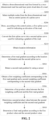
- the method for determining a road gradient specifically includes following steps S202 to S212 and steps S902 to S910.
- S202 Obtain a three-dimensional road line formed by a two-dimensional road line and laser point cloud data of a road.
- the two-dimensional road line may be referred to as a two-dimensional road navigation line, including longitudinal information and transverse information of a road.
- the transverse direction refers to a direction from a center line of the road to two sides of the road
- the longitudinal direction refers to a direction of the center line of the road, that is, a direction in which a vehicle drives along the center line of the road.
- the two-dimensional road line may be a road line displayed on a display screen of the moving terminal in a navigation process.
- the laser point cloud may be a set of laser points obtained by scanning a road surface by using a three-dimensional laser scanner or a photographic scanner.
- the laser point cloud data may be information about the laser point cloud and each laser point.
- the information about the laser point includes information in directions of an X-axis, a Y-axis, and a Z-axis, where information on the X-axis may represent longitudinal information of the road, information on the Y-axis may represent transverse information of the road, and information on the Z-axis may represent elevation information of the road.
- the three-dimensional road line may be a road line obtained by adding the elevation information to the two-dimensional road line.
- the laser point cloud data may be inputted into the moving terminal when an electronic map is produced, or obtained through scanning the road ahead by the moving terminal in a driving process by using a laser.
- an implementation of constructing the three-dimensional road line may include: obtaining the two-dimensional road line and the laser point cloud data of the road; selecting, from the laser point cloud data, a laser point closest to each node on the two-dimensional road line; obtaining an elevation value of the selected laser point; and using the elevation value as an elevation value of the node, corresponding to the selected laser point, on the two-dimensional road line, to obtain the three-dimensional road line.
- the moving terminal may determine the laser point closest to each node on the two-dimensional road line by calculating a Euclidean distance.
- the two-dimensional road line does not include the elevation information of the road, and the three-dimensional laser point includes the elevation information. Therefore, the three-dimensional laser point closest to the road line may be selected, and the elevation information of the selected three-dimensional laser point is used as the elevation information of the node on the road line corresponding to the selected three-dimensional laser point. In this way, the three-dimensional road line including the elevation information may be obtained.
- a laser point closest to the node a may be determined by calculating a Euclidean distance.
- the laser point closest to the node a is a laser point A, and then elevation information of the laser point A is used as elevation information of the node a.
- elevation information of the laser points is obtained, and the elevation information of the laser points is used as elevation information of the nodes on the road line corresponding to the laser points. In this way, a three-dimensional road line including the elevation information may be obtained.
- S204 Select multiple nodes from the three-dimensional road line as control points of a spline curve.
- the spline curve is a curve obtained according to a set of given control points, and the shape of the curve is controlled by the control points.
- the moving terminal may randomly select the multiple nodes from the three-dimensional road line as the control points of the spline curve.
- the moving terminal may alternatively select one node from the three-dimensional road line every other preset distance, thereby selecting the multiple nodes from the three-dimensional road line and using the selected nodes as the control points of the spline curve.
- the moving terminal uses the multiple selected nodes as initial control points, draws, according to the initial control points, an initial spline curve used for indicating an elevation of the road, and calculates a cost function.
- Variables of the cost function are a fitting degree of fitting a curve section between every two initial control points to a three-dimensional laser point cloud near the curve section, and a length of each curve section. Then, the moving terminal continuously adjusts the quantity of the initial control points, and calculates the cost function once during each adjustment, to obtain a minimum value of the cost function; and uses the control points, corresponding to a case when the minimum value is obtained, as control points of a first spline curve, so that the control points of the first spline curve are determined.
- S206 Draw, according to the control points, a first spline curve used for indicating an elevation of the road.
- the spline curve may be a B-spline curve, for example, a uniform B-spline curve or a non-uniform B-spline curve.
- An expression of the spline curve may be a three-dimensional third-order equation, and the expression includes a basis function.
- the elevation of the road is a distance from a point on the road to an absolute datum along a direction of a vertical line.
- An elevation difference is a difference between elevations of two points on the road.
- P i is an i-th control point of the spline curve.
- the moving terminal may connect the control points by using a curve according to a rule of the spline curve, to obtain the first spline curve used for indicating the elevation of the road.
- measurement manners of the elevation of the road may include: leveling measurement, trigonometric elevation measurement, global navigation satellite system (GNSS) elevation measurement, and physical elevation measurement.
- the leveling measurement is to measure a level difference between ground points by using an instrument (for example, a level gauge) capable of providing a horizontal line of sight.
- the gradient of the road may be a gradient of a transverse road slope, a gradient of a longitudinal road slope, and a gradient of a combination of the transverse road slope and the longitudinal road slope. Unless otherwise specified, in a subsequent embodiment, descriptions are provided by using an example in which the gradient of the road is the gradient of the longitudinal road slope.
- the gradient of the road may be considered as a slope of an elevation curve. Therefore, the gradient of the road may be obtained in a manner of taking a derivative of the elevation curve.
- S208 may specifically include: determining a basis function in an equation representing the first spline curve; and taking a derivative of the basis function in the equation representing the first spline curve, and using a curve, obtained by taking the derivative of the basis function, as the second spline curve used for indicating a gradient of the road.
- the corresponding gradient of the road is a fixed value. If the change of the elevation of the road in the ascending direction of the elevation is a non-uniform change, the corresponding gradient of the road is a straight line or a curve.
- the following second spline curve P ' ( z ) used for indicating the gradient of the road may be obtained:
- P z ⁇ s 3 + 3 s 2 + 1 p 0 z + 3 s 3 ⁇ 6 s 2 + 4 p 1 z + ⁇ 3 s 3 + 3 s 2 + 3 s + 1 p 2 z + s 3 p 3 z
- P ′ z ⁇ 3 s 2 + 6 s p 0 z + 9 s 2 ⁇ 12 s p 1 z + ⁇ 9 s 2 + 6 s + 3 p 2 z + 3 s 2 p 3 z
- p 0 z , p 1 z , p 2 z , and p 3 z are elevation information of control points.
- s is a value between 0 and 1.
- the location information is information about a current location of the moving terminal.
- the location information may be latitude and longitude values, or may be coordinate values obtained by converting latitude and longitude values in a terrestrial coordinate system into a three-dimensional rectangular coordinate system corresponding to the three-dimensional road line.
- the moving terminal obtains the location information of the moving terminal through positioning by using a built-in global positioning system (GPS), a BeiDou Navigation Satellite System (BDS), a Galileo Satellite Navigation System, or the like.
- GPS global positioning system
- BDS BeiDou Navigation Satellite System
- Galileo Satellite Navigation System or the like.
- the moving terminal may further convert the location information obtained through positioning into location information in the three-dimensional rectangular coordinate system corresponding to the three-dimensional road line.
- the moving terminal obtains the location information of the moving terminal through positioning by using a mobile communications base station.
- S212 Determine a first road gradient according to the location information and the second spline curve.
- the location information is location information in the three-dimensional rectangular coordinate system corresponding to the three-dimensional road line
- similarity comparison is performed between the location information and a node on the first spline curve, to obtain a node having a maximum similarity to the location information, and the node is substituted into an expression of the second spline curve, to obtain the first road gradient through calculation.
- s may be a similarity. If a Euclidean distance between the location information and a node on the spline curve is minimum, a similarity between the location information and the node is maximum.
- the moving terminal may determine a speed value according to the first road gradient, and adjust a driving speed of the moving terminal in a driving process according to the speed value.
- Different road gradients correspond to different speed values.
- a relatively small road gradient value may correspond to a relatively large speed value
- a relatively large road gradient value may correspond to a relatively small speed value. In this way, safety problems caused by an excessively large driving speed on a road with a relatively large gradient may be avoided.
- the three-dimensional road line is formed by the two-dimensional road line and the laser point cloud data of the road
- the multiple nodes are selected from the three-dimensional road line as the control points to draw the first spline curve used for indicating the elevation of the road
- the first spline curve is converted into the second spline curve used for indicating the gradient of the road. Due to geometric continuity and local constraints of the spline curve itself, consistency and continuity of the road gradient data are ensured, thereby avoiding introduction of a horizontal error. Therefore, when the road gradient is determined according to the second spline curve, precision of the road gradient can be effectively improved.
- S902 Detect a second road gradient by using a sensor.
- the sensor may be a gradient sensor or an angle sensor mounted in the moving terminal, and a gradient value of a road is detected by using the sensor.
- the senor may alternatively be a gradient sensor or an angle sensor mounted on two sides of a road, and a gradient value of a section of road may be detected by using the sensor.
- the sensor may send the measured gradient value to the moving terminal, and the moving terminal receives the gradient value.
- the sensors may be disposed on two sides of a gradient road, for example, disposed under an overpass.
- the first road gradient obtained through the second spline curve used for indicating the gradient of the road may be integrated with the second road gradient detected by the sensor to determine a final road gradient, to reduce an error of the road gradient.
- S904 Obtain a first weighting coefficient corresponding to the first road gradient and a second weighting coefficient corresponding to the second road gradient.
- Both the first weighting coefficient and the second weighting coefficient are values between 0 and 1, and a sum obtained by adding the first weighting coefficient and the second weighting coefficient is 1.
- the moving terminal may determine the value of the first weighting coefficient and the value of the second weighting coefficient respectively according to a quantity of vehicles on the road or an accuracy of a manner used for calculating the road gradient.
- the second weighting coefficient is less than the first weighting coefficient.
- S906 Determine a first product value between the first weighting coefficient and the first road gradient.
- S908 Determine a second product value between the second weighting coefficient and the second road gradient.
- S910 Determine a final road gradient according to the first product value and the second product value.
- the moving terminal adds the first product value and the second product value, and determines a result of the summation as the final road gradient.
- the determined road gradient may be the first road gradient, or a road gradient obtained by integrating the first road gradient and the second road gradient.
- the method may further include: detecting a remaining slope length value of a moving terminal in a driving direction of the moving terminal; determining a user field-of-view region according to the remaining slope length value and the determined road gradient; obtaining a speed value which is corresponding to the road gradient and which is matching the user field-of-view region in a case that the user field-of-view region is smaller than a preset field-of-view region; and adjusting a driving speed of the moving terminal on the road according to the obtained speed value.
- the remaining slope length value is a slope length from a current location of the moving terminal to a position where a gradient ahead is cut off in the driving direction.
- the user field-of-view region may be a region visible to a user, and may be measured by using a maximum visible distance of the user.
- the preset field-of-view region may be a preset region of a fixed size. When the user field-of-view region is not smaller than the preset field-of-view region, the region visible to the user is relatively large, a location of a vehicle ahead can be obtained, and the vehicle ahead does not affect driving of the user.
- a field-of-view region of a user in the moving terminal may be the entire gradient road.
- the field-of-view region of the user may only be a remaining part of the gradient road, and consequently, the field-of-view region of the user is greatly reduced, and if there is a vehicle ahead, there may be a safety threat, and the driving speed needs to be reduced in this case.
- the moving terminal adjusts the driving speed according to the road gradient on a gradient road. Different road gradients may correspond to different driving speeds. A road with a relatively large road gradient corresponds to a relatively low driving speed.
- the first road gradient is integrated with the second road gradient detected by the sensor, thereby reducing an error of the road gradient.
- the driving speed is determined according to the remaining slope length value and the road gradient, to prevent the moving terminal from colliding with a vehicle outside the field-of-view region due to an excessively high driving speed, thereby improving safety of driving.
- the method further includes following steps S402 to S406.
- S402 Determine a column region by using each node on the three-dimensional road line as a reference point and using a preset value as a distance value.
- the reference point may be a center point, for example, the center of a circle, the center of a polygon, or the like.
- the column region may be a region such as a circular column, or a polygonal column.
- the moving terminal obtains nodes on the three-dimensional road line at equal intervals, connects every two neighboring nodes on the three-dimensional road line, and draws two circles by using the nodes at two ends as centers and by using a preset value as a radius, to obtain a circular column including the two circles.
- the moving terminal obtains nodes on the three-dimensional road line at equal intervals, connects every two neighboring nodes on the three-dimensional road line, and draws two polygons by using the nodes at two ends as center points and by using a preset value as a shortest distance, to obtain a column including the two polygons.
- S404 Select, from the laser point cloud data, laser points within the column region.
- S406 Perform point cloud processing on every two neighboring nodes on the three-dimensional road line, to obtain a three-dimensional laser point cloud surrounding the three-dimensional road line.
- the three-dimensional laser point cloud is used for fitting the three-dimensional road line to the three-dimensional laser point cloud.
- FIG. 5 For example, as shown in FIG. 5 , two nodes of the three-dimensional road line are connected and are used as two endpoints of a circular column, a radius range is set, and points falling within the circular column are kept, to obtain a small-scale three-dimensional laser point cloud, as shown in the right figure in FIG. 6 .
- the left figure in FIG. 6 is a laser point cloud related to a road in laser point cloud data
- the right figure in FIG. 6 is a laser point cloud formed by laser points within the circular column.
- the three-dimensional laser point the distance from which to the node on the three-dimensional road line is shortest and satisfies a condition defined by the preset value is kept by using the column region, and a three-dimensional laser point the distance from which to the node on the three-dimensional road line is longer is filtered out, so that the three-dimensional road line may be better fitted to the kept three-dimensional laser point cloud, thereby improving a fitting degree, and further improving an accuracy of the road gradient.
- S204 may specifically include following steps S702 to S710.
- S702 Select multiple nodes from the three-dimensional road line.
- the moving terminal may randomly select the multiple nodes from the three-dimensional road line, or may alternatively select one node from the three-dimensional road line every other preset distance, thereby selecting the multiple nodes from the three-dimensional road line.
- S704 Obtain a three-dimensional laser point cloud corresponding to a sub-section three-dimensional road line between every two neighboring nodes of the multiple selected nodes.
- the sub-section three-dimensional road line is a three-dimensional road line connecting two neighboring nodes.
- the three-dimensional laser point cloud corresponding to the sub-section three-dimensional road line is a three-dimensional laser point cloud surrounding the sub-section three-dimensional road line.
- the moving terminal determines positions of nodes at two ends of the sub-section three-dimensional road line, and then captures the three-dimensional laser point cloud between the positions of the nodes at two ends.
- S706 Determine a length value of each sub-section three-dimensional road line and a fitting degree value of fitting the sub-section three-dimensional road line to the three-dimensional laser point cloud corresponding to the sub-section three-dimensional road line.
- the length value of each sub-section three-dimensional road line between the nodes is calculated, and a Euclidean distance between a node on the each sub-section three-dimensional road line and a laser point in the three-dimensional laser point cloud corresponding to the sub-section three-dimensional road line is calculated.
- the fitting degree value is determined according to the Euclidean distance obtained through calculation. A smaller Euclidean distance indicates a larger fitting degree value, that is, a higher fitting degree. A larger Euclidean distance indicates a smaller fitting degree value, that is, a lower fitting degree.
- the fitting degree value may be a value between 0 and 1, where 1 may indicate 100% fitting.
- the moving terminal may also select a sub-section three-dimensional road line whose length value exceeds a preset threshold from the sub-section three-dimensional road lines, record the length value of the selected sub-section three-dimensional road line, and perform S708 when the fitting degree value of fitting the sub-section three-dimensional road line to the corresponding three-dimensional laser point cloud is determined.
- S708 Determine an accumulated value of differences between each of the length values and the fitting degree values corresponding to the length value.
- the selected nodes may be used as the control points of the initial spline curve.
- the accumulated value is small enough, it may indicate that the B-spline curve drawn by using the multiple selected nodes as the control points is the first spline curve.
- the moving terminal after calculating the length value of each sub-section three-dimensional road line and the fitting degree value of fitting the sub-section three-dimensional road line to the corresponding three-dimensional laser point cloud, the moving terminal adds the length values, to obtain a first sum.
- the moving terminal adds the fitting degree values, to obtain a second sum.
- the moving terminal calculates a difference between the first sum and the second sum, to obtain a difference.
- the obtained difference is the foregoing accumulated value.
- the moving terminal calculates a difference between each length value and the fitting degree value corresponding to the length value, and then adds results obtained through calculation of the differences, to obtain the accumulated value.
- S710 Use the multiple selected nodes as the control points of the spline curve in a case that the accumulated value satisfies a preset condition.
- the preset condition may be a condition of being less than or equal to a preset threshold, and the preset threshold may be small enough.
- the multiple nodes are used as the control points of the spline curve, and the B-spline curve drawn according to the control points is the first spline curve.
- the accumulated value of the differences between the length values of the sub-section three-dimensional road lines and the fitting degree values of fitting the sub-section three-dimensional road lines to the corresponding three-dimensional laser point clouds is first determined. Only when the accumulated value satisfies the preset condition, the multiple selected nodes are used as the control points of the spline curve, and then the spline curve is drawn according to the control points, to obtain the first spline curve, thereby improving an accuracy of the road gradient.
- the method may further include following steps S802 to S808.
- S802 Obtain a cost function with a length as a first variable and a fitting degree as a second variable.
- the moving terminal establishes the cost function, where the first variable of the cost function is the length and the second variable of the cost function is the fitting degree.
- data _ fitting may be a Euclidean distance between a sub-section three-dimensional road line and a three-dimensional laser point cloud, ⁇ may be a corresponding weight coefficient, and ⁇ ⁇ data _ fitting is a fitting degree of fitting a sub-section three-dimensional road line between every two nodes to the three-dimensional laser point cloud surrounding the sub-section three-dimensional road line.
- # length may be a length value of each sub-section three-dimensional road line, or may be a length value of a sub-section three-dimensional road line whose length exceeds a preset threshold, or may be a quantity of sub-section three-dimensional road lines whose length exceeds the preset threshold; ⁇ may be a corresponding weight coefficient, and ⁇ ⁇ #length is a length of each section of curve.
- the moving terminal may randomly adjust the quantity of the multiple selected nodes, or may adjust the quantity of the multiple selected nodes each time according to a set quantity.
- S804 may specifically include: increasing, by the moving terminal, the quantity of the multiple selected nodes, or decreasing the quantity of the multiple selected nodes.
- the moving terminal may randomly increase the quantity of the multiple selected nodes, or may increase the quantity of the multiple selected nodes each time according to a set quantity.
- the moving terminal may randomly decrease the quantity of the multiple selected nodes, or may decrease the quantity of the multiple selected nodes each time according to a set quantity.
- S806 Determine a minimum value of the cost function according to a length value of each sub-section three-dimensional road line formed after each adjustment in the quantity of the multiple selected nodes and a fitting degree value of fitting each sub-section three-dimensional road line formed after each adjustment in the quantity of the multiple selected nodes to the three-dimensional laser point cloud corresponding to the sub-section three-dimensional road line.
- S806 may specifically include: determining a length value of each sub-section three-dimensional road line formed after each increase in the quantity of the multiple selected nodes and a fitting degree value of fitting each sub-section three-dimensional road line formed after each increase in the quantity of the multiple selected nodes to the three-dimensional laser point cloud corresponding to the sub-section three-dimensional road line; and determining the minimum value of the cost function in a case that the cost function first decreases and then increases during successive substitution of the length values and the fitting degree values corresponding to the length values that are determined by increasing the quantity of the multiple selected nodes.
- the added node is selected from the three-dimensional road line.
- the quantity of the selected nodes continues to be increased based on the original selected nodes until the cost function begins to increase, so that the minimum value may be obtained.
- the nodes corresponding to the obtained minimum value are the control points of the final spline curve, and the spline curve drawn according to the control points is the first spline curve.
- the operation of adding a node this time is accepted according to a preset probability, and the quantity of the selected nodes continues to be increased on this basis. If the cost function still increases, the operation of adding a node this time is rejected, the quantity of the selected nodes starts to be decreased, and the cost function is calculated.
- S806 may specifically include: determining a length value of each sub-section three-dimensional road line formed after each decrease in the quantity of the multiple selected nodes and a fitting degree value of fitting each sub-section three-dimensional road line formed after each decrease in the quantity of the multiple selected nodes to the three-dimensional laser point cloud corresponding to the sub-section three-dimensional road line; and determining the minimum value of the cost function in a case that the cost function first decreases and then increases during successive substitution of the length values and the fitting degree values corresponding to the length values that are determined by decreasing the quantity of the multiple selected nodes.
- the quantity of the selected nodes continues to be decreased based on the original selected nodes until the cost function begins to increase, so that the minimum value may be obtained.
- the nodes corresponding to the obtained minimum value are the control points of the final spline curve, and the spline curve drawn according to the control points is an optimal spline curve.
- the operation of reducing a node this time is accepted according to a preset probability, and the quantity of the selected nodes continues to be decreased on this basis. If the cost function still increases, the operation of reducing a node this time is rejected, the quantity of the selected nodes starts to be increased, and the cost function is calculated.
- a value of the cost function is calculated. If the value of the cost function is minimum when the quantity of the selected nodes is adjusted to s, the s selected nodes are used as the control points of the spline curve, and a spline curve, that is, the first spline curve, is drawn according to the control points.
- the quantity of the selected nodes is adjusted, and then it is determined whether the cost function can obtain a minimum value.
- the minimum value it indicates that the nodes corresponding to a case when the minimum value is obtained are optimal control points, and the spline curve is drawn according to the control points, to obtain the first spline curve, thereby improving an accuracy of the road gradient.
- the method mainly includes: selecting, directly along a two-dimensional road line, three-dimensional laser points closest to nodes on the two-dimensional road line from three-dimensional laser point cloud data, reading elevation values of the obtained three-dimensional laser points, and then calculating an elevation difference and a horizontal distance between two three-dimensional laser points, to determine the road gradient.
- a quality of the acquired road data is not considered.
- data noise introduced by an acquisition device data missing caused by a scanning resolution, data missing caused by a scanning angle of a device, and spuriousness of elevation data caused by positioning precision are not considered.
- data missing is caused by occlusion of other vehicles, and consequently, there are problems of unstable data and poor precision when the elevation is determined from the data.
- the two-dimensional road line data when the elevation information is extracted by using the two-dimensional road line, the two-dimensional road line data inevitably introduces an error in a horizontal direction. Horizontal coordinates also cause instability, causing introduction of an error during elevation information extraction.
- an embodiment of the present disclosure provides a method for determining a road gradient. As shown in FIG. 9 , specific content of the method may include following (1) to (4).
- a laser point having a closest Euclidean distance to the node is found from three-dimensional laser point cloud.
- An elevation value of the found laser point is used as an elevation value of the node corresponding to the found laser point on the two-dimensional road line. In this way, the two-dimensional road line is converted into the three-dimensional road line.
- E ⁇ ⁇ ⁇ data _ fitting + ⁇ ⁇ # length ;
- the first term is a fitting degree of fitting a curve between every two knots to a three-dimensional laser point cloud surrounding the curve, and the second term is a length of each curve.
- data _ fitting may be a Euclidean distance between a curve between knots and the three-dimensional laser point cloud
- ⁇ may be a corresponding weight coefficient
- ⁇ ⁇ data _ fitting is a fitting degree
- # length may be a quantity of curves whose lengths exceed a preset threshold
- ⁇ may be a corresponding weight coefficient.
- the cost function is minimized by randomly perturbing the knots.
- a manner of perturbation is to randomly add or randomly reduce the knots.
- the added knot is selected from the three-dimensional road line.
- the three-dimensional B-spline curve is discretized at fixed intervals, and an elevation value of each point is taken to form the elevation curve.
- One road gradient may be determined by using the longitudinal slope spline curve.
- a driving speed of self-driving needs is to be adjusted according to the road gradient
- a dynamic road gradient further needs to be detected by using a sensor.
- a weighted sum of the two road gradients is calculated, to obtain a final road gradient. Then, the driving speed of self-driving is adjusted according to the final obtained road gradient.
- This solution can effectively resist data noise and data missing, and implement an industrial-level data precision requirement.
- An elevation value and a road gradient obtained by using this solution may be widely applied to self-driving and advanced auxiliary driving, to provide early warning on sight blocking caused by a gradient ahead and adjust the vehicle speed in a timely manner.
- collision with a vehicle outside the field-of-view region due to an excessively high vehicle speed is prevented, thereby improving safety.
- comfort of driving on a road in a gradient region is ensured, and driving experience of a user is improved.
- FIG. 2 , FIG. 4 , and FIG. 7 to FIG. 8 are schematic flowcharts of a method for determining a road gradient according to an embodiment. It is to be understood that, although the steps in the flowcharts of FIG. 2 , FIG. 4 , and FIG. 7 to FIG. 8 are sequentially displayed according to indication of arrows, the steps are not necessarily sequentially performed in the sequence indicated by the arrows. Unless explicitly specified in this specification, the steps are performed without any strict sequence limitation, and may be performed in another sequence. In addition, at least some steps in FIG. 2 , FIG. 4 , and FIG. 7 to FIG. 8 may include multiple substeps or multiple stages. The substeps or the stages are not necessarily performed at the same moment, and instead may be performed at different moments.
- FIG. 10 is a diagram showing an internal structure of a computer device according to an embodiment.
- the computer device may be specifically the moving terminal in FIG. 1 .
- the computer device includes a processor, a memory, a network interface, an input apparatus, and a display screen that are connected via a system bus.
- the memory includes a non-volatile storage medium and an internal memory.
- the non-volatile storage medium of the computer device stores an operating system, and may further store a computer program.
- the computer program when executed by the processor, may cause the processor to implement the method for determining a road gradient.
- the internal memory may also store a computer program.
- the computer program when executed by the processor, may cause the processor to perform the method for determining a road gradient.
- the display screen of the computer device may be a liquid crystal display screen or an electronic ink display screen.
- the input apparatus of the computer device may be a touch layer covering the display screen, or may be a key, a trackball, or a touchpad disposed on a housing of the computer device, or may be an external keyboard, touchpad, mouse, or the like.
- FIG. 10 is only a block diagram of a partial structure related to the solution of this disclosure, and does not constitute a limitation to the computer device to which the solution of this disclosure is applied.
- the computer device may include more or fewer components than those shown in FIG. 10 , or some components may be combined, or a different component deployment may be used.
- the computer device may be a moving terminal (or a server), or may be a device on the moving terminal (or the server) that is configured to perform the method for determining a road gradient.
- a computer device includes a memory and a processor.
- the memory stores a computer program.
- the computer program when executed by the processor, causes the processor to perform following operations: obtaining a three-dimensional road line formed by a two-dimensional road line and laser point cloud data of a road; selecting multiple nodes from the three-dimensional road line as control points of a spline curve; drawing, according to the control points, a first spline curve used for indicating an elevation of the road; converting the first spline curve into a second spline curve used for indicating a gradient of the road; and obtaining location information of a moving terminal, and determining a first road gradient according to the location information and the second spline curve; detecting a second road gradient of the two-dimensional road line by using a sensor; obtaining a first weighting coefficient corresponding to the first road gradient and a second weighting coefficient corresponding to the second road gradient; determining a first product value between the first weighting coefficient and the first road
- the computer program when executed by the processor, causes the processor to perform following operations: obtaining the two-dimensional road line and the laser point cloud data of the road; selecting, from the laser point cloud data, a laser point closest to each node on the two-dimensional road line; obtaining an elevation value of the selected laser point; and using the elevation value as an elevation value of the node, corresponding the selected laser point, on the two-dimensional road line, to obtain the three-dimensional road line.
- the computer program when executed by the processor, causes the processor to perform following operations: determining a column region by using each node on the three-dimensional road line as a reference point and using a preset value as a distance value; selecting, from the laser point cloud data, laser points within the column region; and performing point cloud processing on every two neighboring nodes on the three-dimensional road line, to obtain a three-dimensional laser point cloud surrounding the three-dimensional road line, the three-dimensional laser point cloud being used for fitting the three-dimensional road line to the three-dimensional laser point cloud.
- the computer program when executed by the processor, causes the processor to perform following operations: selecting multiple nodes from the three-dimensional road line; obtaining a three-dimensional laser point cloud corresponding to a sub-section three-dimensional road line between every two neighboring nodes of the multiple selected nodes; determining a length value of each sub-section three-dimensional road line and a fitting degree value of fitting the sub-section three-dimensional road line to the three-dimensional laser point cloud corresponding to the sub-section three-dimensional road line; determining an accumulated value of differences between each of the length values and the fitting degree value corresponding to the length value; and using the multiple selected nodes as the control points of the spline curve in a case that the accumulated value satisfies a preset condition.
- the computer program when executed by the processor, causes the processor to perform following operations: obtaining a cost function with a length as a first variable and a fitting degree as a second variable; adjusting a quantity of the multiple selected nodes; determining a minimum value of the cost function according to a length value of each sub-section three-dimensional road line formed after each adjustment in the quantity of the multiple selected nodes and a fitting degree value of fitting each sub-section three-dimensional road line formed after each adjustment in the quantity of the multiple selected nodes to the three-dimensional laser point cloud corresponding to the sub-section three-dimensional road line; and using the nodes, corresponding to a case when the minimum value is obtained, as the control points of the spline curve.
- the computer program when executed by the processor, causes the processor to perform following operations: increasing the quantity of the multiple selected nodes; and the determining a minimum value of the cost function according to a length value of each sub-section three-dimensional road line formed after each adjustment in the quantity of the multiple selected nodes and a fitting degree value of fitting each sub-section three-dimensional road line formed after each adjustment in the quantity of the multiple selected nodes to the three-dimensional laser point cloud corresponding to the sub-section three-dimensional road line includes: determining a length value of each sub-section three-dimensional road line formed after each increase in the quantity of the multiple selected nodes and a fitting degree value of fitting each sub-section three-dimensional road line formed after each increase in the quantity of the multiple selected nodes to the three-dimensional laser point cloud corresponding to the sub-section three-dimensional road line; and determining the minimum value of the cost function in a case that the cost function first decreases and then increases during successive substitution of the length values and the fitting degree values corresponding to the length values that are determined by increasing the quantity of
- the computer program when executed by the processor, causes the processor to perform following operations: decreasing the quantity of the multiple selected nodes; and the determining a minimum value of the cost function according to a length value of each sub-section three-dimensional road line formed after each adjustment in the quantity of the multiple selected nodes and a fitting degree value of fitting each sub-section three-dimensional road line formed after each adjustment in the quantity of the multiple selected nodes to the three-dimensional laser point cloud corresponding to the sub-section three-dimensional road line includes: determining a length value of each sub-section three-dimensional road line formed after each decrease in the quantity of the multiple selected nodes and a fitting degree value of fitting each sub-section three-dimensional road line formed after each decrease in the quantity of the multiple selected nodes to the three-dimensional laser point cloud corresponding to the sub-section three-dimensional road line; and determining the minimum value of the cost function in a case that the cost function first decreases and then increases during successive substitution of the length values and the fitting degree values corresponding to the length values that are determined by decreasing the quantity of
- the computer program when executed by the processor, causes the processor to perform following operations: determining a basis function in an equation representing the first spline curve; and taking a derivative of the basis function in the equation representing the first spline curve, and using a curve, obtained by taking the derivative of the basis function, as the second spline curve used for indicating a gradient of the road.
- the computer program when executed by the processor, causes the processor to perform following operations: detecting a remaining slope length value of a moving terminal in a driving direction of the moving terminal, wherein the remaining slope length value is a slope length from a current location of the moving terminal to a position where a gradient ahead of the moving terminal is cut off in the driving direction; determining a user field-of-view region according to the remaining slope length value and the determined road gradient; obtaining a speed value which is corresponding to the first road gradient and which is matching the user field-of-view region in a case that the user field-of-view region is smaller than a preset field-of-view region; and adjusting a driving speed of the moving terminal on the road according to the obtained speed value.
- a computer-readable storage medium stores a computer program.
- the computer program when executed by a processor, causes the processor to perform following operations: obtaining a three-dimensional road line formed by a two-dimensional road line and laser point cloud data of a road; selecting multiple nodes from the three-dimensional road line as control points of a spline curve; drawing, according to the control points, a first spline curve used for indicating an elevation of the road; converting the first spline curve into a second spline curve used for indicating a gradient of the road; and obtaining location information of a moving terminal, and determining a first road gradient according to the location information and the second spline curve; detecting a second road gradient of the two-dimensional road line by using a sensor; obtaining a first weighting coefficient corresponding to the first road gradient and a second weighting coefficient corresponding to the second road gradient; determining a first product value between the first weighting coefficient and the first road gradient; determining
- the computer program when executed by the processor, causes the processor to perform following operations: obtaining the two-dimensional road line and the laser point cloud data of the road; selecting, from the laser point cloud data, a laser point closest to each node on the two-dimensional road line; obtaining an elevation value of the selected laser point; and using the elevation value as an elevation value of the node, corresponding the selected laser point, on the two-dimensional road line, to obtain the three-dimensional road line.
- the computer program when executed by the processor, causes the processor to perform following operations: determining a column region by using each node on the three-dimensional road line as a reference point and using a preset value as a distance value; selecting, from the laser point cloud data, laser points within the column region; and performing point cloud processing on every two neighboring nodes on the three-dimensional road line, to obtain a three-dimensional laser point cloud surrounding the three-dimensional road line, the three-dimensional laser point cloud being used for fitting the three-dimensional road line to the three-dimensional laser point cloud.
- the computer program when executed by the processor, causes the processor to perform following operations: selecting multiple nodes from the three-dimensional road line; obtaining a three-dimensional laser point cloud corresponding to a sub-section three-dimensional road line between every two neighboring nodes of the multiple selected nodes; determining a length value of each sub-section three-dimensional road line and a fitting degree value of fitting the sub-section three-dimensional road line to the three-dimensional laser point cloud corresponding to the sub-section three-dimensional road line; determining an accumulated value of differences between each of the length values and the fitting degree value corresponding to the length value; and using the multiple selected nodes as the control points of the spline curve in a case that the accumulated value satisfies a preset condition.
- the computer program when executed by the processor, causes the processor to perform following operations: obtaining a cost function with a length as a first variable and a fitting degree as a second variable; adjusting a quantity of the multiple selected nodes; determining a minimum value of the cost function according to a length value of each sub-section three-dimensional road line formed after each adjustment in the quantity of the multiple selected nodes and a fitting degree value of fitting each sub-section three-dimensional road line formed after each adjustment in the quantity of the multiple selected nodes to the three-dimensional laser point cloud corresponding to the sub-section three-dimensional road line; and using the nodes, corresponding to a case when the minimum value is obtained, as the control points of the spline curve.
- the computer program when executed by the processor, causes the processor to perform following operations: increasing the quantity of the multiple selected nodes; and the determining a minimum value of the cost function according to a length value of each sub-section three-dimensional road line formed after each adjustment in the quantity of the multiple selected nodes and a fitting degree value of fitting each sub-section three-dimensional road line formed after each adjustment in the quantity of the multiple selected nodes to the three-dimensional laser point cloud corresponding to the sub-section three-dimensional road line includes: determining a length value of each sub-section three-dimensional road line formed after each increase in the quantity of the multiple selected nodes and a fitting degree value of fitting each sub-section three-dimensional road line formed after each increase in the quantity of the multiple selected nodes to the three-dimensional laser point cloud corresponding to the sub-section three-dimensional road line; and determining the minimum value of the cost function in a case that the cost function first decreases and then increases during successive substitution of the length values and the fitting degree values corresponding to the length values that are determined by increasing the quantity of
- the computer program when executed by the processor, causes the processor to perform following operations: decreasing the quantity of the multiple selected nodes; and the determining a minimum value of the cost function according to a length value of each sub-section three-dimensional road line formed after each adjustment in the quantity of the multiple selected nodes and a fitting degree value of fitting each sub-section three-dimensional road line formed after each adjustment in the quantity of the multiple selected nodes to the three-dimensional laser point cloud corresponding to the sub-section three-dimensional road line includes: determining a length value of each sub-section three-dimensional road line formed after each decrease in the quantity of the multiple selected nodes and a fitting degree value of fitting each sub-section three-dimensional road line formed after each decrease in the quantity of the multiple selected nodes to the three-dimensional laser point cloud corresponding to the sub-section three-dimensional road line; and determining the minimum value of the cost function in a case that the cost function first decreases and then increases during successive substitution of the length values and the fitting degree values corresponding to the length values that are determined by decreasing the quantity of
- the computer program when executed by the processor, causes the processor to perform following operations: determining a basis function in an equation representing the first spline curve; and taking a derivative of the basis function in the equation representing the first spline curve, and using a curve, obtained by taking the derivative of the basis function, as the second spline curve used for indicating a gradient of the road.
- the computer program when executed by the processor, causes the processor to perform following operations: detecting a remaining slope length value of a moving terminal in a driving direction of the moving terminal, where the remaining slope length value is a slope length from a current location of the moving terminal to a position where a gradient ahead of the moving terminal is cut off in the driving direction; determining a user field-of-view region according to the remaining slope length value and the determined road gradient; obtaining a speed value which is corresponding to the first road gradient and which is matching the user field-of-view region in a case that the user field-of-view region is smaller than a preset field-of-view region; and adjusting a driving speed of the moving terminal on the road according to the obtained speed value.
- the non-volatile memory may include a read-only memory (ROM), a programmable ROM (PROM), an electrically programmable ROM (EPROM), an electrically erasable programmable ROM (EEPROM), or a flash memory.
- ROM read-only memory
- PROM programmable ROM
- EPROM electrically programmable ROM
- EEPROM electrically erasable programmable ROM
- the volatile memory may include a random access memory (RAM) or an external cache.
- the RAM is available in multiple forms, such as a static RAM (SRAM), a dynamic RAM (DRAM), a synchronous DRAM (SDRAM), a double data rate SDRAM (DDRSDRAM), an enhanced SDRAM (ESDRAM), a synchronous link (Synchlink) DRAM (SLDRAM), a Rambus direct RAM (RDRAM), a direct Rambus dynamic RAM (DRDRAM), and a Rambus dynamic RAM (RDRAM).
- SRAM static RAM
- DRAM dynamic RAM
- SDRAM synchronous DRAM
- DDRSDRAM double data rate SDRAM
- ESDRAM enhanced SDRAM
- SLDRAM synchronous link
- RDRAM Rambus direct RAM
- DRAM direct Rambus dynamic RAM
- RDRAM Rambus dynamic RAM
Landscapes
- Engineering & Computer Science (AREA)
- Physics & Mathematics (AREA)
- General Physics & Mathematics (AREA)
- Electromagnetism (AREA)
- Computer Networks & Wireless Communication (AREA)
- Radar, Positioning & Navigation (AREA)
- Remote Sensing (AREA)
- Computer Vision & Pattern Recognition (AREA)
- Theoretical Computer Science (AREA)
- Mathematical Physics (AREA)
- Transportation (AREA)
- Mechanical Engineering (AREA)
- Optics & Photonics (AREA)
- Automation & Control Theory (AREA)
- Traffic Control Systems (AREA)
- Length Measuring Devices By Optical Means (AREA)
Claims (11)
- Verfahren zum Bestimmen eines Straßengradienten, wobei das Verfahren auf eine Computervorrichtung angewandt wird, wobei das Verfahren Folgendes umfasst:Gewinnen einer dreidimensionalen Straßenlinie, die von einer zweidimensionalen Straßenlinie und Laserpunkt-Cloud-Daten einer Straße gebildet wird, (S202),Auswählen mehrerer Knoten aus der dreidimensionalen Straßenlinie als Steuerpunkte einer Spline-Kurve (S204),Zeichnen einer ersten Spline-Kurve, die zum Angeben einer Höhe der Straße verwendet wird, gemäß den Steuerpunkten (S206),Umwandeln der ersten Spline-Kurve in eine zweite Spline-Kurve, die zum Angeben eines Gradienten der Straße verwendet wird, (S208),Gewinnen von Standortinformationen eines sich bewegenden Endgeräts (S210) und Bestimmen eines ersten Straßengradienten gemäß den Standortinformationen und der zweiten Spline-Kurve (S212),Erkennen eines zweiten Straßengradienten der zweidimensionalen Straßenlinie mit Hilfe eines Sensors (S902),Gewinnen eines ersten Gewichtungskoeffizienten, der dem ersten Straßengradienten entspricht, und eines zweiten Gewichtungskoeffizienten, der dem zweiten Straßengradienten entspricht, (S904),Bestimmen eines ersten Produktwertes aus dem ersten Gewichtungskoeffizienten und dem ersten Straßengradienten (S906),Bestimmen eines zweiten Produktwertes aus dem zweiten Gewichtungskoeffizienten und dem zweiten Straßengradienten (S908) undBestimmen eines endgültigen Straßengradienten gemäß dem ersten Produktwert und dem zweiten Produktwert (S910).
- Verfahren nach Anspruch 1, wobei das Gewinnen einer dreidimensionalen Straßenlinie, die von einer zweidimensionalen Straßenlinie und Laserpunkt-Cloud-Daten einer Straße gebildet wird, (S202) Folgendes umfasst:Gewinnen der zweidimensionalen Straßenlinie und der Laserpunkt-Cloud-Daten der Straße,Auswählen eines Laserpunktes, der jedem Knoten auf der zweidimensionalen Straßenlinie am nächsten liegt, aus den Laserpunkt-Cloud-Daten,Gewinnen eines Höhenwertes des ausgewählten Laserpunktes undVerwenden des Höhenwertes als einen Höhenwert des Knotens, der dem ausgewählten Laserpunkt entspricht, auf der zweidimensionalen Straßenlinie, um die dreidimensionale Straßenlinie zu gewinnen.
- Verfahren nach Anspruch 1, wobei das Verfahren vor dem Auswählen mehrerer Knoten aus der dreidimensionalen Straßenlinie als Steuerpunkte einer Spline-Kurve (S204) ferner Folgendes umfasst:Bestimmen einer Spaltenregion mit Hilfe jedes Knotens auf der dreidimensionalen Straßenlinie als einen Referenzpunkt und Verwenden eines voreingestellten Wertes als einen Distanzwert (S402),Auswählen von Laserpunkten innerhalb der Spaltenregion aus den Laserpunkt-Cloud-Daten (S404) undDurchführen einer Punktwolkenverarbeitung an jeweils zwei benachbarten Knoten auf der dreidimensionalen Straßenlinie, um eine dreidimensionale Laserpunktwolke zu gewinnen, welche die dreidimensionale Straßenlinie umgibt, wobei die dreidimensionale Laserpunktwolke zum Anpassen (Fitten) der dreidimensionalen Straßenlinie an die dreidimensionale Laserpunktwolke verwendet wird (S406).
- Verfahren nach Anspruch 3, wobei das Auswählen mehrerer Knoten aus der dreidimensionalen Straßenlinie als Steuerpunkte einer Spline-Kurve (S204) ferner Folgendes umfasst:Auswählen mehrerer Knoten aus der dreidimensionalen Straßenlinie (S702),Gewinnen einer dreidimensionalen Laserpunktwolke, die einem Unterabschnitt der dreidimensionalen Straßenlinie zwischen jeweils zwei benachbarten Knoten der mehreren ausgewählten Knoten entspricht, (S704),Bestimmen eines Längenwertes jedes Unterabschnitts der dreidimensionalen Straßenlinie und eines Anpassungsgradwertes des Anpassens des Unterabschnitts der dreidimensionalen Straßenlinie an die dreidimensionale Laserpunktwolke, die dem Unterabschnitt der dreidimensionalen Straßenlinie entspricht, (S706),Bestimmen eines akkumulierten Wertes von Differenzen zwischen jedem der Längenwerte und dem Anpassungsgradwert, der dem Längenwert entspricht, (S708) undVerwenden der mehreren ausgewählten Knoten als die Steuerpunkte der Spline-Kurve, wenn der akkumulierte Wert der Differenzen eine voreingestellte Bedingung erfüllt, (S710).
- Verfahren nach Anspruch 4, ferner Folgendes umfassend:Gewinnen einer Kostenfunktion mit einer Länge als eine erste Variable und einem Anpassungsgrad als eine zweite Variable (S802),Justieren einer Menge der mehreren ausgewählten Knoten (S804),Bestimmen eines Minimalwertes der Kostenfunktion gemäß einem Längenwert jedes Unterabschnitts der dreidimensionalen Straßenlinie, der nach jedem Justieren der Menge der mehreren ausgewählten Knoten gebildet wird, und einem Anpassungsgradwert des Anpassens jedes Unterabschnitts der dreidimensionalen Straßenlinie, der nach jedem Justieren der Menge der mehreren ausgewählten Knoten gebildet wird, an die dreidimensionale Laserpunktwolke, die dem Unterabschnitt der dreidimensionalen Straßenlinie entspricht, (S806) undVerwenden der Knoten, die dem Fall entsprechen, wenn der Minimalwert erzielt ist, als die Steuerpunkte der Spline-Kurve (S808).
- Verfahren nach Anspruch 5, wobei das Justieren einer Menge der mehreren ausgewählten Knoten (S804) Folgendes umfasst:Erhöhen der Menge der mehreren ausgewählten Knoten undwobei das Bestimmen eines Minimalwertes der Kostenfunktion gemäß einem Längenwert jedes Unterabschnitts der dreidimensionalen Straßenlinie, der nach jedem Justieren der Menge der mehreren ausgewählten Knoten gebildet wird, und einem Anpassungsgradwert des Anpassens jedes Unterabschnitts der dreidimensionalen Straßenlinie, der nach jedem Justieren der Menge der mehreren ausgewählten Knoten gebildet wird, an die dreidimensionale Laserpunktwolke, die dem Unterabschnitt der dreidimensionalen Straßenlinie entspricht, Folgendes umfasst:Bestimmen eines Längenwertes jedes Unterabschnitts der dreidimensionalen Straßenlinie, der nach jedem Erhöhen der Menge der mehreren ausgewählten Knoten gebildet wird, und eines Anpassungsgradwertes des Anpassens jedes Unterabschnitts der dreidimensionalen Straßenlinie, der nach jedem Erhöhen der Menge der mehreren ausgewählten Knoten gebildet wird, an die dreidimensionale Laserpunktwolke, die dem Unterabschnitt der dreidimensionalen Straßenlinie entspricht, undBestimmen des Minimalwertes der Kostenfunktion, wenn die Kostenfunktion während einer schrittweisen Substitution der Längenwerte und der Anpassungsgradwerte, die den Längenwerten entsprechen, die durch Erhöhen der Menge der mehreren ausgewählten Knoten bestimmt werden, zuerst abnimmt und dann zunimmt.
- Verfahren nach Anspruch 5, wobei das Justieren einer Menge der mehreren ausgewählten Knoten (S804) Folgendes umfasst:Verringern der Menge der mehreren ausgewählten Knoten, undwobei das Bestimmen eines Minimalwertes der Kostenfunktion gemäß einem Längenwert jedes Unterabschnitts der dreidimensionalen Straßenlinie, der nach jedem Justieren der Menge der mehreren ausgewählten Knoten gebildet wird, und einem Anpassungsgradwert des Anpassens jedes Unterabschnitts der dreidimensionalen Straßenlinie, der nach jedem Justieren der Menge der mehreren ausgewählten Knoten gebildet wird, an die dreidimensionale Laserpunktwolke, die dem Unterabschnitt der dreidimensionalen Straßenlinie entspricht, Folgendes umfasst:Bestimmen eines Längenwertes jedes Unterabschnitts der dreidimensionalen Straßenlinie, der nach jedem Verringern der Menge der mehreren ausgewählten Knoten gebildet wird, und eines Anpassungsgradwertes des Anpassens jedes Unterabschnitts der dreidimensionalen Straßenlinie, der nach jedem Verringern der Menge der mehreren ausgewählten Knoten gebildet wird, an die dreidimensionale Laserpunktwolke, die dem Unterabschnitt der dreidimensionalen Straßenlinie entspricht, undBestimmen des Minimalwertes der Kostenfunktion, wenn die Kostenfunktion während einer schrittweisen Substitution der Längenwerte und der Anpassungsgradwerte, die den Längenwerten entsprechen, die durch Verringern der Menge der mehreren ausgewählten Knoten bestimmt werden, zuerst abnimmt und dann zunimmt.
- Verfahren nach Anspruch 1, wobei das Umwandeln der ersten Spline-Kurve in eine zweite Spline-Kurve, die zum Angeben eines Gradienten der Straße verwendet wird, (S208) Folgendes umfasst:Bestimmen einer Basisfunktion in einer Gleichung, welche die erste Spline-Kurve darstellt, undÜbernehmen einer Ableitung der Basisfunktion in der Gleichung, welche die erste Spline-Kurve darstellt, und Verwenden einer Kurve, die durch Übernehmen der Ableitung von der Basisfunktion gewonnen wird, als die zweite Spline-Kurve, die zum Angeben eines Gradienten der Straße verwendet wird.
- Verfahren nach einem der Ansprüche 1 bis 8, ferner Folgendes umfassend:Erkennen eines verbleibenden Neigungslängenwertes eines sich bewegenden Endgeräts in einer Fahrtrichtung des sich bewegenden Endgeräts, wobei der verbleibende Neigungslängenwert eine Länge einer Neigung von einem gegenwärtigen Standort des sich bewegenden Endgeräts zu einer Position ist, an der ein Gradient vor dem sich bewegenden Endgerät in der Fahrtrichtung abgeschnitten wird,Bestimmen einer Region des Gesichtsfeldes eines Benutzers gemäß dem verbleibenden Neigungslängenwert und dem bestimmten Straßengradienten,Gewinnen eines Geschwindigkeitswertes, der dem ersten Straßengradienten entspricht und der zur Region des Gesichtsfeldes des Benutzers passt, wenn die Region des Gesichtsfeldes des Benutzers kleiner als eine voreingestellte Gesichtsfeldregion ist, undJustieren einer Fahrgeschwindigkeit des sich bewegenden Endgeräts auf der Straße gemäß dem gewonnenen Geschwindigkeitswert.
- Speichermedium, das ein Computerprogramm speichert, wobei das Computerprogramm bei Ausführung durch einen Prozessor den Prozessor veranlasst, das Verfahren nach einem der Ansprüche 1 bis 9 auszuführen.
- Computervorrichtung, einen Speicher und einen Prozessor umfassend, wobei der Speicher ein Computerprogramm speichert, wobei das Computerprogramm bei Ausführung durch einen Prozessor den Prozessor veranlasst, das Verfahren nach einem der Ansprüche 1 bis 9 auszuführen.
Applications Claiming Priority (2)
| Application Number | Priority Date | Filing Date | Title |
|---|---|---|---|
| CN201811143089.1A CN110161513B (zh) | 2018-09-28 | 2018-09-28 | 估计道路坡度的方法、装置、存储介质和计算机设备 |
| PCT/CN2019/108231 WO2020063774A1 (zh) | 2018-09-28 | 2019-09-26 | 确定道路坡度的方法、装置、存储介质和计算机设备 |
Publications (3)
| Publication Number | Publication Date |
|---|---|
| EP3757613A1 EP3757613A1 (de) | 2020-12-30 |
| EP3757613A4 EP3757613A4 (de) | 2021-05-26 |
| EP3757613B1 true EP3757613B1 (de) | 2023-07-19 |
Family
ID=67645089
Family Applications (1)
| Application Number | Title | Priority Date | Filing Date |
|---|---|---|---|
| EP19864762.0A Active EP3757613B1 (de) | 2018-09-28 | 2019-09-26 | Verfahren und vorrichtung zur bestimmung der strassenneigung, speichermedium und computergerät |
Country Status (4)
| Country | Link |
|---|---|
| US (1) | US11370445B2 (de) |
| EP (1) | EP3757613B1 (de) |
| CN (1) | CN110161513B (de) |
| WO (1) | WO2020063774A1 (de) |
Families Citing this family (20)
| Publication number | Priority date | Publication date | Assignee | Title |
|---|---|---|---|---|
| CN110161513B (zh) * | 2018-09-28 | 2023-11-14 | 腾讯科技(北京)有限公司 | 估计道路坡度的方法、装置、存储介质和计算机设备 |
| CN111998828B (zh) * | 2020-09-23 | 2022-05-10 | 暨南大学 | 一种基于便携式gps的道路坡度估算方法 |
| CN112215952B (zh) * | 2020-10-26 | 2021-08-13 | 湖北亿咖通科技有限公司 | 曲线绘制方法、计算机存储介质及电子设备 |
| CN112836576B (zh) * | 2020-12-30 | 2021-09-24 | 北京理工大学 | 一种越野道路路面模型的快速分析方法 |
| CN112862844B (zh) * | 2021-02-20 | 2024-01-05 | 园测信息科技股份有限公司 | 基于车载点云数据的道路边界交互式提取方法 |
| CN112884896B (zh) * | 2021-02-23 | 2024-06-14 | 中国建筑第八工程局有限公司 | 基于bim技术的异形坡道三维模型快速生成方法 |
| CN113340304B (zh) * | 2021-06-03 | 2023-02-17 | 青岛慧拓智能机器有限公司 | 坡度提取方法及装置 |
| US12497040B2 (en) * | 2021-11-16 | 2025-12-16 | Hyundai Mobis Co., Ltd. | Vehicle control system and vehicle driving method using the vehicle control system |
| CN114162126B (zh) * | 2021-12-28 | 2024-07-05 | 上海洛轲智能科技有限公司 | 车辆控制方法、装置、设备、介质及产品 |
| CN114821522B (zh) * | 2022-03-29 | 2025-05-16 | 东南大学 | 基于车载激光点云数据的城市道路横坡和超高值计算方法 |
| CN114985300B (zh) * | 2022-04-27 | 2024-03-01 | 佛山科学技术学院 | 一种瓦楞纸板生产线出口纸板分类方法及系统 |
| CN114998538A (zh) * | 2022-06-09 | 2022-09-02 | 珠海金山数字网络科技有限公司 | 虚拟场景的道路生成方法及装置 |
| CN114969944B (zh) * | 2022-06-17 | 2024-04-26 | 滁州学院 | 一种高精度道路dem构建方法 |
| CN117570912B (zh) * | 2022-08-08 | 2024-07-19 | 兰州交通大学 | 一种无需通视无大气折光影响的三角高程测量方法 |
| CN115035138B (zh) * | 2022-08-10 | 2022-11-22 | 武汉御驾科技有限公司 | 基于众包数据的路面坡度提取方法 |
| CN115423835B (zh) * | 2022-11-02 | 2023-03-24 | 中汽创智科技有限公司 | 杆状物点云数据处理方法、装置、电子设备及存储介质 |
| CN116047464B (zh) * | 2023-01-28 | 2023-08-11 | 武汉理工大学 | 一种基于激光雷达的地下矿区坡度检测方法及系统 |
| CN118395577B (zh) * | 2024-06-26 | 2024-08-27 | 武汉大学 | 一种沥青路面变量铣刨参数设计方法及装置 |
| CN119479922B (zh) * | 2024-10-22 | 2025-08-26 | 浙江海正生物材料股份有限公司 | 一种基于高固厌氧生物分解试验结果的拟合求导法分析评价塑料抗降解性能的方法 |
| CN120894507B (zh) * | 2025-09-28 | 2025-12-16 | 理工雷科智途(北京)科技有限公司 | 一种井工矿巷道壁的实时提取方法及系统 |
Family Cites Families (18)
| Publication number | Priority date | Publication date | Assignee | Title |
|---|---|---|---|---|
| JP3656469B2 (ja) * | 1999-08-05 | 2005-06-08 | 三菱ふそうトラック・バス株式会社 | 道路勾配算出装置 |
| US7007011B1 (en) * | 2001-10-03 | 2006-02-28 | Navteq North America, Llc | Method for representing the vertical component of road geometry and computing grade or slope |
| GB2471276A (en) * | 2009-06-22 | 2010-12-29 | Bae Systems Plc | Terrain sensing apparatus for an autonomous vehicle |
| CN101930623B (zh) * | 2009-06-26 | 2012-12-12 | 比亚迪股份有限公司 | 一种三维道路模型化方法及装置 |
| CN102201035B (zh) * | 2011-05-12 | 2016-02-03 | 北京星河易达科技有限公司 | 一种计算前方道路弯度/坡度的预估方法 |
| JP5088401B2 (ja) * | 2010-06-23 | 2012-12-05 | 日本電気株式会社 | 道路構造測定方法および道路面測定装置 |
| DE102010042065B4 (de) * | 2010-10-06 | 2022-12-08 | Robert Bosch Gmbh | Verfahren und Vorrichtung zum Ausgeben einer Empfehlung eines Ausrollen-Lassens des Fahrzeugs für ein Fahrerassistenzsystem des Fahrzeugs |
| KR101884018B1 (ko) * | 2012-02-21 | 2018-08-29 | 현대엠엔소프트 주식회사 | 라이다 데이터를 이용한 도로의 곡선반경, 종단 및 횡단 경사도 산출 방법 |
| US8793035B2 (en) * | 2012-08-31 | 2014-07-29 | Ford Global Technologies, Llc | Dynamic road gradient estimation |
| CN103711050B (zh) * | 2013-12-31 | 2016-04-06 | 中交第二公路勘察设计研究院有限公司 | 一种激光雷达道路改扩建勘测设计方法 |
| CN104123730B (zh) * | 2014-07-31 | 2016-09-14 | 武汉大学 | 基于道路特征的遥感影像与激光点云配准方法及系统 |
| CN105444735A (zh) * | 2014-08-22 | 2016-03-30 | 北京协进科技发展有限公司 | 一种道路坡度的确定方法及装置 |
| CN105806347B (zh) * | 2014-12-31 | 2018-10-12 | 易图通科技(北京)有限公司 | 一种坡度路段真三维导航方法及一种真三维导航设备 |
| KR102521655B1 (ko) * | 2016-09-01 | 2023-04-13 | 삼성전자주식회사 | 자율 주행 방법 및 장치 |
| CN108267747B (zh) * | 2017-01-03 | 2021-10-22 | 中交宇科(北京)空间信息技术有限公司 | 基于激光点云的道路特征提取方法和装置 |
| US20190005667A1 (en) * | 2017-07-24 | 2019-01-03 | Muhammad Zain Khawaja | Ground Surface Estimation |
| CN107560599B (zh) * | 2017-09-04 | 2020-05-12 | 清华大学 | 一种基于特征点采样和曲线拟合的道路坡度数据处理方法 |
| CN110161513B (zh) * | 2018-09-28 | 2023-11-14 | 腾讯科技(北京)有限公司 | 估计道路坡度的方法、装置、存储介质和计算机设备 |
-
2018
- 2018-09-28 CN CN201811143089.1A patent/CN110161513B/zh active Active
-
2019
- 2019-09-26 WO PCT/CN2019/108231 patent/WO2020063774A1/zh not_active Ceased
- 2019-09-26 EP EP19864762.0A patent/EP3757613B1/de active Active
-
2020
- 2020-10-15 US US17/071,605 patent/US11370445B2/en active Active
Also Published As
| Publication number | Publication date |
|---|---|
| WO2020063774A1 (zh) | 2020-04-02 |
| US11370445B2 (en) | 2022-06-28 |
| US20210024074A1 (en) | 2021-01-28 |
| CN110161513A (zh) | 2019-08-23 |
| EP3757613A4 (de) | 2021-05-26 |
| EP3757613A1 (de) | 2020-12-30 |
| CN110161513B (zh) | 2023-11-14 |
Similar Documents
| Publication | Publication Date | Title |
|---|---|---|
| EP3757613B1 (de) | Verfahren und vorrichtung zur bestimmung der strassenneigung, speichermedium und computergerät | |
| CN114323050B (zh) | 车辆定位方法、装置和电子设备 | |
| CN110709890B (zh) | 地图数据修正方法及装置 | |
| CN107850445B (zh) | 用于生成及使用定位参考数据的方法及系统 | |
| CN114829971A (zh) | 一种激光雷达的标定方法、装置及存储介质 | |
| WO2022127532A1 (zh) | 一种激光雷达与imu的外参标定方法、装置及设备 | |
| Holgado‐Barco et al. | Semiautomatic extraction of road horizontal alignment from a mobile LiDAR system | |
| US11525682B2 (en) | Host vehicle position estimation device | |
| US12299928B2 (en) | Method, device and storage medium for road slope predicating | |
| KR20210111180A (ko) | 위치 추적 방법, 장치, 컴퓨팅 기기 및 컴퓨터 판독 가능한 저장 매체 | |
| KR102441073B1 (ko) | 자이로 센싱값 보상 장치, 그를 포함한 시스템 및 그 방법 | |
| JP2020500290A (ja) | 位置特定基準データを生成及び使用する方法及びシステム | |
| JP7637185B2 (ja) | 情報処理装置 | |
| JP2025065215A (ja) | 地図作成装置、制御方法、プログラム及び記憶媒体 | |
| CN102207389A (zh) | 车辆位置识别系统 | |
| Marinelli et al. | Mobile mapping systems and spatial data collection strategies assessment in the identification of horizontal alignment of highways | |
| JP2024103654A (ja) | 計測精度算出装置、自己位置推定装置、制御方法、プログラム及び記憶媒体 | |
| WO2018212292A1 (ja) | 情報処理装置、制御方法、プログラム及び記憶媒体 | |
| CN111241224A (zh) | 目标距离估计的方法、系统、计算机设备和存储介质 | |
| CN114581615A (zh) | 一种数据处理方法、装置、设备和存储介质 | |
| US11753018B2 (en) | Lane-type and roadway hypotheses determinations in a road model | |
| JP2025013679A (ja) | 情報処理装置、制御方法、プログラム及び記憶媒体 | |
| KR102568112B1 (ko) | Rdp 알고리즘 기반의 도로 구배정보 모델링 장치 및 방법 | |
| CN116359937B (zh) | 一种车辆定位方法、装置、计算机设备及介质 | |
| JP7658008B2 (ja) | 情報処理装置、制御方法、プログラム及び記憶媒体 |
Legal Events
| Date | Code | Title | Description |
|---|---|---|---|
| STAA | Information on the status of an ep patent application or granted ep patent |
Free format text: STATUS: THE INTERNATIONAL PUBLICATION HAS BEEN MADE |
|
| PUAI | Public reference made under article 153(3) epc to a published international application that has entered the european phase |
Free format text: ORIGINAL CODE: 0009012 |
|
| STAA | Information on the status of an ep patent application or granted ep patent |
Free format text: STATUS: REQUEST FOR EXAMINATION WAS MADE |
|
| 17P | Request for examination filed |
Effective date: 20200921 |
|
| AK | Designated contracting states |
Kind code of ref document: A1 Designated state(s): AL AT BE BG CH CY CZ DE DK EE ES FI FR GB GR HR HU IE IS IT LI LT LU LV MC MK MT NL NO PL PT RO RS SE SI SK SM TR |
|
| AX | Request for extension of the european patent |
Extension state: BA ME |
|
| A4 | Supplementary search report drawn up and despatched |
Effective date: 20210423 |
|
| RIC1 | Information provided on ipc code assigned before grant |
Ipc: G01S 17/06 20060101AFI20210419BHEP Ipc: G06T 17/00 20060101ALI20210419BHEP Ipc: B60W 40/076 20120101ALI20210419BHEP Ipc: G01S 7/48 20060101ALI20210419BHEP Ipc: G01S 17/08 20060101ALI20210419BHEP Ipc: G01S 17/89 20200101ALI20210419BHEP Ipc: G01S 17/931 20200101ALI20210419BHEP |
|
| DAV | Request for validation of the european patent (deleted) | ||
| DAX | Request for extension of the european patent (deleted) | ||
| RAP3 | Party data changed (applicant data changed or rights of an application transferred) |
Owner name: TENCENT TECHNOLOGY (SHENZHEN) COMPANY LIMITED |
|
| STAA | Information on the status of an ep patent application or granted ep patent |
Free format text: STATUS: EXAMINATION IS IN PROGRESS |
|
| 17Q | First examination report despatched |
Effective date: 20230126 |
|
| GRAP | Despatch of communication of intention to grant a patent |
Free format text: ORIGINAL CODE: EPIDOSNIGR1 |
|
| STAA | Information on the status of an ep patent application or granted ep patent |
Free format text: STATUS: GRANT OF PATENT IS INTENDED |
|
| INTG | Intention to grant announced |
Effective date: 20230414 |
|
| GRAS | Grant fee paid |
Free format text: ORIGINAL CODE: EPIDOSNIGR3 |
|
| GRAA | (expected) grant |
Free format text: ORIGINAL CODE: 0009210 |
|
| STAA | Information on the status of an ep patent application or granted ep patent |
Free format text: STATUS: THE PATENT HAS BEEN GRANTED |
|
| AK | Designated contracting states |
Kind code of ref document: B1 Designated state(s): AL AT BE BG CH CY CZ DE DK EE ES FI FR GB GR HR HU IE IS IT LI LT LU LV MC MK MT NL NO PL PT RO RS SE SI SK SM TR |
|
| REG | Reference to a national code |
Ref country code: GB Ref legal event code: FG4D |
|
| REG | Reference to a national code |
Ref country code: CH Ref legal event code: EP |
|
| REG | Reference to a national code |
Ref country code: DE Ref legal event code: R096 Ref document number: 602019033258 Country of ref document: DE |
|
| REG | Reference to a national code |
Ref country code: IE Ref legal event code: FG4D |
|
| REG | Reference to a national code |
Ref country code: LT Ref legal event code: MG9D |
|
| REG | Reference to a national code |
Ref country code: NL Ref legal event code: MP Effective date: 20230719 |
|
| REG | Reference to a national code |
Ref country code: AT Ref legal event code: MK05 Ref document number: 1590002 Country of ref document: AT Kind code of ref document: T Effective date: 20230719 |
|
| PG25 | Lapsed in a contracting state [announced via postgrant information from national office to epo] |
Ref country code: NL Free format text: LAPSE BECAUSE OF FAILURE TO SUBMIT A TRANSLATION OF THE DESCRIPTION OR TO PAY THE FEE WITHIN THE PRESCRIBED TIME-LIMIT Effective date: 20230719 |
|
| PG25 | Lapsed in a contracting state [announced via postgrant information from national office to epo] |
Ref country code: GR Free format text: LAPSE BECAUSE OF FAILURE TO SUBMIT A TRANSLATION OF THE DESCRIPTION OR TO PAY THE FEE WITHIN THE PRESCRIBED TIME-LIMIT Effective date: 20231020 |
|
| PG25 | Lapsed in a contracting state [announced via postgrant information from national office to epo] |
Ref country code: IS Free format text: LAPSE BECAUSE OF FAILURE TO SUBMIT A TRANSLATION OF THE DESCRIPTION OR TO PAY THE FEE WITHIN THE PRESCRIBED TIME-LIMIT Effective date: 20231119 |
|
| PG25 | Lapsed in a contracting state [announced via postgrant information from national office to epo] |
Ref country code: SE Free format text: LAPSE BECAUSE OF FAILURE TO SUBMIT A TRANSLATION OF THE DESCRIPTION OR TO PAY THE FEE WITHIN THE PRESCRIBED TIME-LIMIT Effective date: 20230719 Ref country code: RS Free format text: LAPSE BECAUSE OF FAILURE TO SUBMIT A TRANSLATION OF THE DESCRIPTION OR TO PAY THE FEE WITHIN THE PRESCRIBED TIME-LIMIT Effective date: 20230719 Ref country code: PT Free format text: LAPSE BECAUSE OF FAILURE TO SUBMIT A TRANSLATION OF THE DESCRIPTION OR TO PAY THE FEE WITHIN THE PRESCRIBED TIME-LIMIT Effective date: 20231120 Ref country code: NO Free format text: LAPSE BECAUSE OF FAILURE TO SUBMIT A TRANSLATION OF THE DESCRIPTION OR TO PAY THE FEE WITHIN THE PRESCRIBED TIME-LIMIT Effective date: 20231019 Ref country code: LV Free format text: LAPSE BECAUSE OF FAILURE TO SUBMIT A TRANSLATION OF THE DESCRIPTION OR TO PAY THE FEE WITHIN THE PRESCRIBED TIME-LIMIT Effective date: 20230719 Ref country code: LT Free format text: LAPSE BECAUSE OF FAILURE TO SUBMIT A TRANSLATION OF THE DESCRIPTION OR TO PAY THE FEE WITHIN THE PRESCRIBED TIME-LIMIT Effective date: 20230719 Ref country code: IS Free format text: LAPSE BECAUSE OF FAILURE TO SUBMIT A TRANSLATION OF THE DESCRIPTION OR TO PAY THE FEE WITHIN THE PRESCRIBED TIME-LIMIT Effective date: 20231119 Ref country code: HR Free format text: LAPSE BECAUSE OF FAILURE TO SUBMIT A TRANSLATION OF THE DESCRIPTION OR TO PAY THE FEE WITHIN THE PRESCRIBED TIME-LIMIT Effective date: 20230719 Ref country code: GR Free format text: LAPSE BECAUSE OF FAILURE TO SUBMIT A TRANSLATION OF THE DESCRIPTION OR TO PAY THE FEE WITHIN THE PRESCRIBED TIME-LIMIT Effective date: 20231020 Ref country code: FI Free format text: LAPSE BECAUSE OF FAILURE TO SUBMIT A TRANSLATION OF THE DESCRIPTION OR TO PAY THE FEE WITHIN THE PRESCRIBED TIME-LIMIT Effective date: 20230719 Ref country code: AT Free format text: LAPSE BECAUSE OF FAILURE TO SUBMIT A TRANSLATION OF THE DESCRIPTION OR TO PAY THE FEE WITHIN THE PRESCRIBED TIME-LIMIT Effective date: 20230719 |
|
| PG25 | Lapsed in a contracting state [announced via postgrant information from national office to epo] |
Ref country code: PL Free format text: LAPSE BECAUSE OF FAILURE TO SUBMIT A TRANSLATION OF THE DESCRIPTION OR TO PAY THE FEE WITHIN THE PRESCRIBED TIME-LIMIT Effective date: 20230719 |
|
| REG | Reference to a national code |
Ref country code: DE Ref legal event code: R097 Ref document number: 602019033258 Country of ref document: DE |
|
| PG25 | Lapsed in a contracting state [announced via postgrant information from national office to epo] |
Ref country code: ES Free format text: LAPSE BECAUSE OF FAILURE TO SUBMIT A TRANSLATION OF THE DESCRIPTION OR TO PAY THE FEE WITHIN THE PRESCRIBED TIME-LIMIT Effective date: 20230719 |
|
| PG25 | Lapsed in a contracting state [announced via postgrant information from national office to epo] |
Ref country code: SM Free format text: LAPSE BECAUSE OF FAILURE TO SUBMIT A TRANSLATION OF THE DESCRIPTION OR TO PAY THE FEE WITHIN THE PRESCRIBED TIME-LIMIT Effective date: 20230719 Ref country code: RO Free format text: LAPSE BECAUSE OF FAILURE TO SUBMIT A TRANSLATION OF THE DESCRIPTION OR TO PAY THE FEE WITHIN THE PRESCRIBED TIME-LIMIT Effective date: 20230719 Ref country code: ES Free format text: LAPSE BECAUSE OF FAILURE TO SUBMIT A TRANSLATION OF THE DESCRIPTION OR TO PAY THE FEE WITHIN THE PRESCRIBED TIME-LIMIT Effective date: 20230719 Ref country code: EE Free format text: LAPSE BECAUSE OF FAILURE TO SUBMIT A TRANSLATION OF THE DESCRIPTION OR TO PAY THE FEE WITHIN THE PRESCRIBED TIME-LIMIT Effective date: 20230719 Ref country code: DK Free format text: LAPSE BECAUSE OF FAILURE TO SUBMIT A TRANSLATION OF THE DESCRIPTION OR TO PAY THE FEE WITHIN THE PRESCRIBED TIME-LIMIT Effective date: 20230719 Ref country code: CZ Free format text: LAPSE BECAUSE OF FAILURE TO SUBMIT A TRANSLATION OF THE DESCRIPTION OR TO PAY THE FEE WITHIN THE PRESCRIBED TIME-LIMIT Effective date: 20230719 Ref country code: SK Free format text: LAPSE BECAUSE OF FAILURE TO SUBMIT A TRANSLATION OF THE DESCRIPTION OR TO PAY THE FEE WITHIN THE PRESCRIBED TIME-LIMIT Effective date: 20230719 |
|
| REG | Reference to a national code |
Ref country code: CH Ref legal event code: PL |
|
| PG25 | Lapsed in a contracting state [announced via postgrant information from national office to epo] |
Ref country code: LU Free format text: LAPSE BECAUSE OF NON-PAYMENT OF DUE FEES Effective date: 20230926 |
|
| PLBE | No opposition filed within time limit |
Free format text: ORIGINAL CODE: 0009261 |
|
| STAA | Information on the status of an ep patent application or granted ep patent |
Free format text: STATUS: NO OPPOSITION FILED WITHIN TIME LIMIT |
|
| REG | Reference to a national code |
Ref country code: BE Ref legal event code: MM Effective date: 20230930 |
|
| PG25 | Lapsed in a contracting state [announced via postgrant information from national office to epo] |
Ref country code: LU Free format text: LAPSE BECAUSE OF NON-PAYMENT OF DUE FEES Effective date: 20230926 Ref country code: IT Free format text: LAPSE BECAUSE OF FAILURE TO SUBMIT A TRANSLATION OF THE DESCRIPTION OR TO PAY THE FEE WITHIN THE PRESCRIBED TIME-LIMIT Effective date: 20230719 Ref country code: MC Free format text: LAPSE BECAUSE OF FAILURE TO SUBMIT A TRANSLATION OF THE DESCRIPTION OR TO PAY THE FEE WITHIN THE PRESCRIBED TIME-LIMIT Effective date: 20230719 |
|
| 26N | No opposition filed |
Effective date: 20240422 |
|
| REG | Reference to a national code |
Ref country code: IE Ref legal event code: MM4A |
|
| PG25 | Lapsed in a contracting state [announced via postgrant information from national office to epo] |
Ref country code: IE Free format text: LAPSE BECAUSE OF NON-PAYMENT OF DUE FEES Effective date: 20230926 |
|
| PG25 | Lapsed in a contracting state [announced via postgrant information from national office to epo] |
Ref country code: CH Free format text: LAPSE BECAUSE OF NON-PAYMENT OF DUE FEES Effective date: 20230930 |
|
| PG25 | Lapsed in a contracting state [announced via postgrant information from national office to epo] |
Ref country code: IE Free format text: LAPSE BECAUSE OF NON-PAYMENT OF DUE FEES Effective date: 20230926 Ref country code: CH Free format text: LAPSE BECAUSE OF NON-PAYMENT OF DUE FEES Effective date: 20230930 Ref country code: SI Free format text: LAPSE BECAUSE OF FAILURE TO SUBMIT A TRANSLATION OF THE DESCRIPTION OR TO PAY THE FEE WITHIN THE PRESCRIBED TIME-LIMIT Effective date: 20230719 |
|
| PG25 | Lapsed in a contracting state [announced via postgrant information from national office to epo] |
Ref country code: BE Free format text: LAPSE BECAUSE OF NON-PAYMENT OF DUE FEES Effective date: 20230930 |
|
| PG25 | Lapsed in a contracting state [announced via postgrant information from national office to epo] |
Ref country code: BG Free format text: LAPSE BECAUSE OF FAILURE TO SUBMIT A TRANSLATION OF THE DESCRIPTION OR TO PAY THE FEE WITHIN THE PRESCRIBED TIME-LIMIT Effective date: 20230719 |
|
| PG25 | Lapsed in a contracting state [announced via postgrant information from national office to epo] |
Ref country code: BG Free format text: LAPSE BECAUSE OF FAILURE TO SUBMIT A TRANSLATION OF THE DESCRIPTION OR TO PAY THE FEE WITHIN THE PRESCRIBED TIME-LIMIT Effective date: 20230719 |
|
| PG25 | Lapsed in a contracting state [announced via postgrant information from national office to epo] |
Ref country code: CY Free format text: LAPSE BECAUSE OF FAILURE TO SUBMIT A TRANSLATION OF THE DESCRIPTION OR TO PAY THE FEE WITHIN THE PRESCRIBED TIME-LIMIT; INVALID AB INITIO Effective date: 20190926 |
|
| PG25 | Lapsed in a contracting state [announced via postgrant information from national office to epo] |
Ref country code: HU Free format text: LAPSE BECAUSE OF FAILURE TO SUBMIT A TRANSLATION OF THE DESCRIPTION OR TO PAY THE FEE WITHIN THE PRESCRIBED TIME-LIMIT; INVALID AB INITIO Effective date: 20190926 |
|
| PGFP | Annual fee paid to national office [announced via postgrant information from national office to epo] |
Ref country code: DE Payment date: 20250919 Year of fee payment: 7 |
|
| PGFP | Annual fee paid to national office [announced via postgrant information from national office to epo] |
Ref country code: GB Payment date: 20250923 Year of fee payment: 7 |
|
| PGFP | Annual fee paid to national office [announced via postgrant information from national office to epo] |
Ref country code: FR Payment date: 20250924 Year of fee payment: 7 |
|
| PG25 | Lapsed in a contracting state [announced via postgrant information from national office to epo] |
Ref country code: TR Free format text: LAPSE BECAUSE OF FAILURE TO SUBMIT A TRANSLATION OF THE DESCRIPTION OR TO PAY THE FEE WITHIN THE PRESCRIBED TIME-LIMIT Effective date: 20230719 |