EP3757588A1 - Battery management device - Google Patents
Battery management device Download PDFInfo
- Publication number
- EP3757588A1 EP3757588A1 EP19859461.6A EP19859461A EP3757588A1 EP 3757588 A1 EP3757588 A1 EP 3757588A1 EP 19859461 A EP19859461 A EP 19859461A EP 3757588 A1 EP3757588 A1 EP 3757588A1
- Authority
- EP
- European Patent Office
- Prior art keywords
- voltage
- measurement
- battery
- bus bar
- switching element
- Prior art date
- Legal status (The legal status is an assumption and is not a legal conclusion. Google has not performed a legal analysis and makes no representation as to the accuracy of the status listed.)
- Granted
Links
Images


Classifications
-
- G—PHYSICS
- G01—MEASURING; TESTING
- G01R—MEASURING ELECTRIC VARIABLES; MEASURING MAGNETIC VARIABLES
- G01R31/00—Arrangements for testing electric properties; Arrangements for locating electric faults; Arrangements for electrical testing characterised by what is being tested not provided for elsewhere
- G01R31/36—Arrangements for testing, measuring or monitoring the electrical condition of accumulators or electric batteries, e.g. capacity or state of charge [SoC]
- G01R31/396—Acquisition or processing of data for testing or for monitoring individual cells or groups of cells within a battery
-
- G—PHYSICS
- G01—MEASURING; TESTING
- G01R—MEASURING ELECTRIC VARIABLES; MEASURING MAGNETIC VARIABLES
- G01R31/00—Arrangements for testing electric properties; Arrangements for locating electric faults; Arrangements for electrical testing characterised by what is being tested not provided for elsewhere
- G01R31/36—Arrangements for testing, measuring or monitoring the electrical condition of accumulators or electric batteries, e.g. capacity or state of charge [SoC]
- G01R31/367—Software therefor, e.g. for battery testing using modelling or look-up tables
-
- B—PERFORMING OPERATIONS; TRANSPORTING
- B60—VEHICLES IN GENERAL
- B60R—VEHICLES, VEHICLE FITTINGS, OR VEHICLE PARTS, NOT OTHERWISE PROVIDED FOR
- B60R16/00—Electric or fluid circuits specially adapted for vehicles and not otherwise provided for; Arrangement of elements of electric or fluid circuits specially adapted for vehicles and not otherwise provided for
- B60R16/02—Electric or fluid circuits specially adapted for vehicles and not otherwise provided for; Arrangement of elements of electric or fluid circuits specially adapted for vehicles and not otherwise provided for electric constitutive elements
- B60R16/03—Electric or fluid circuits specially adapted for vehicles and not otherwise provided for; Arrangement of elements of electric or fluid circuits specially adapted for vehicles and not otherwise provided for electric constitutive elements for supply of electrical power to vehicle subsystems or for
- B60R16/033—Electric or fluid circuits specially adapted for vehicles and not otherwise provided for; Arrangement of elements of electric or fluid circuits specially adapted for vehicles and not otherwise provided for electric constitutive elements for supply of electrical power to vehicle subsystems or for characterised by the use of electrical cells or batteries
-
- G—PHYSICS
- G01—MEASURING; TESTING
- G01R—MEASURING ELECTRIC VARIABLES; MEASURING MAGNETIC VARIABLES
- G01R19/00—Arrangements for measuring currents or voltages or for indicating presence or sign thereof
- G01R19/0084—Measuring voltage only
-
- G—PHYSICS
- G01—MEASURING; TESTING
- G01R—MEASURING ELECTRIC VARIABLES; MEASURING MAGNETIC VARIABLES
- G01R19/00—Arrangements for measuring currents or voltages or for indicating presence or sign thereof
- G01R19/10—Measuring sum, difference or ratio
-
- G—PHYSICS
- G01—MEASURING; TESTING
- G01R—MEASURING ELECTRIC VARIABLES; MEASURING MAGNETIC VARIABLES
- G01R19/00—Arrangements for measuring currents or voltages or for indicating presence or sign thereof
- G01R19/165—Indicating that current or voltage is either above or below a predetermined value or within or outside a predetermined range of values
- G01R19/16528—Indicating that current or voltage is either above or below a predetermined value or within or outside a predetermined range of values using digital techniques or performing arithmetic operations
-
- G—PHYSICS
- G01—MEASURING; TESTING
- G01R—MEASURING ELECTRIC VARIABLES; MEASURING MAGNETIC VARIABLES
- G01R31/00—Arrangements for testing electric properties; Arrangements for locating electric faults; Arrangements for electrical testing characterised by what is being tested not provided for elsewhere
- G01R31/36—Arrangements for testing, measuring or monitoring the electrical condition of accumulators or electric batteries, e.g. capacity or state of charge [SoC]
- G01R31/364—Battery terminal connectors with integrated measuring arrangements
-
- G—PHYSICS
- G01—MEASURING; TESTING
- G01R—MEASURING ELECTRIC VARIABLES; MEASURING MAGNETIC VARIABLES
- G01R31/00—Arrangements for testing electric properties; Arrangements for locating electric faults; Arrangements for electrical testing characterised by what is being tested not provided for elsewhere
- G01R31/36—Arrangements for testing, measuring or monitoring the electrical condition of accumulators or electric batteries, e.g. capacity or state of charge [SoC]
- G01R31/371—Arrangements for testing, measuring or monitoring the electrical condition of accumulators or electric batteries, e.g. capacity or state of charge [SoC] with remote indication, e.g. on external chargers
-
- G—PHYSICS
- G01—MEASURING; TESTING
- G01R—MEASURING ELECTRIC VARIABLES; MEASURING MAGNETIC VARIABLES
- G01R31/00—Arrangements for testing electric properties; Arrangements for locating electric faults; Arrangements for electrical testing characterised by what is being tested not provided for elsewhere
- G01R31/36—Arrangements for testing, measuring or monitoring the electrical condition of accumulators or electric batteries, e.g. capacity or state of charge [SoC]
- G01R31/382—Arrangements for monitoring battery or accumulator variables, e.g. SoC
- G01R31/3835—Arrangements for monitoring battery or accumulator variables, e.g. SoC involving only voltage measurements
-
- G—PHYSICS
- G01—MEASURING; TESTING
- G01R—MEASURING ELECTRIC VARIABLES; MEASURING MAGNETIC VARIABLES
- G01R31/00—Arrangements for testing electric properties; Arrangements for locating electric faults; Arrangements for electrical testing characterised by what is being tested not provided for elsewhere
- G01R31/36—Arrangements for testing, measuring or monitoring the electrical condition of accumulators or electric batteries, e.g. capacity or state of charge [SoC]
- G01R31/382—Arrangements for monitoring battery or accumulator variables, e.g. SoC
- G01R31/3842—Arrangements for monitoring battery or accumulator variables, e.g. SoC combining voltage and current measurements
-
- H—ELECTRICITY
- H01—ELECTRIC ELEMENTS
- H01M—PROCESSES OR MEANS, e.g. BATTERIES, FOR THE DIRECT CONVERSION OF CHEMICAL ENERGY INTO ELECTRICAL ENERGY
- H01M10/00—Secondary cells; Manufacture thereof
- H01M10/42—Methods or arrangements for servicing or maintenance of secondary cells or secondary half-cells
- H01M10/425—Structural combination with electronic components, e.g. electronic circuits integrated to the outside of the casing
-
- H—ELECTRICITY
- H01—ELECTRIC ELEMENTS
- H01M—PROCESSES OR MEANS, e.g. BATTERIES, FOR THE DIRECT CONVERSION OF CHEMICAL ENERGY INTO ELECTRICAL ENERGY
- H01M10/00—Secondary cells; Manufacture thereof
- H01M10/42—Methods or arrangements for servicing or maintenance of secondary cells or secondary half-cells
- H01M10/48—Accumulators combined with arrangements for measuring, testing or indicating the condition of cells, e.g. the level or density of the electrolyte
- H01M10/482—Accumulators combined with arrangements for measuring, testing or indicating the condition of cells, e.g. the level or density of the electrolyte for several batteries or cells simultaneously or sequentially
-
- H—ELECTRICITY
- H01—ELECTRIC ELEMENTS
- H01M—PROCESSES OR MEANS, e.g. BATTERIES, FOR THE DIRECT CONVERSION OF CHEMICAL ENERGY INTO ELECTRICAL ENERGY
- H01M50/00—Constructional details or processes of manufacture of the non-active parts of electrochemical cells other than fuel cells, e.g. hybrid cells
- H01M50/20—Mountings; Secondary casings or frames; Racks, modules or packs; Suspension devices; Shock absorbers; Transport or carrying devices; Holders
- H01M50/204—Racks, modules or packs for multiple batteries or multiple cells
-
- H—ELECTRICITY
- H01—ELECTRIC ELEMENTS
- H01M—PROCESSES OR MEANS, e.g. BATTERIES, FOR THE DIRECT CONVERSION OF CHEMICAL ENERGY INTO ELECTRICAL ENERGY
- H01M50/00—Constructional details or processes of manufacture of the non-active parts of electrochemical cells other than fuel cells, e.g. hybrid cells
- H01M50/50—Current conducting connections for cells or batteries
- H01M50/502—Interconnectors for connecting terminals of adjacent batteries; Interconnectors for connecting cells outside a battery casing
- H01M50/505—Interconnectors for connecting terminals of adjacent batteries; Interconnectors for connecting cells outside a battery casing comprising a single busbar
-
- H—ELECTRICITY
- H02—GENERATION; CONVERSION OR DISTRIBUTION OF ELECTRIC POWER
- H02J—ELECTRIC POWER NETWORKS; CIRCUIT ARRANGEMENTS OR SYSTEMS FOR SUPPLYING OR DISTRIBUTING ELECTRIC POWER; SYSTEMS FOR STORING ELECTRIC ENERGY
- H02J7/00—Circuit arrangements for charging or discharging batteries or for supplying loads from batteries
- H02J7/865—Battery or charger load switching, e.g. concurrent charging and load supply
-
- G—PHYSICS
- G01—MEASURING; TESTING
- G01R—MEASURING ELECTRIC VARIABLES; MEASURING MAGNETIC VARIABLES
- G01R19/00—Arrangements for measuring currents or voltages or for indicating presence or sign thereof
- G01R19/165—Indicating that current or voltage is either above or below a predetermined value or within or outside a predetermined range of values
- G01R19/16533—Indicating that current or voltage is either above or below a predetermined value or within or outside a predetermined range of values characterised by the application
- G01R19/16538—Indicating that current or voltage is either above or below a predetermined value or within or outside a predetermined range of values characterised by the application in AC or DC supplies
- G01R19/16542—Indicating that current or voltage is either above or below a predetermined value or within or outside a predetermined range of values characterised by the application in AC or DC supplies for batteries
-
- G—PHYSICS
- G01—MEASURING; TESTING
- G01R—MEASURING ELECTRIC VARIABLES; MEASURING MAGNETIC VARIABLES
- G01R31/00—Arrangements for testing electric properties; Arrangements for locating electric faults; Arrangements for electrical testing characterised by what is being tested not provided for elsewhere
- G01R31/50—Testing of electric apparatus, lines, cables or components for short-circuits, continuity, leakage current or incorrect line connections
- G01R31/54—Testing for continuity
-
- G—PHYSICS
- G01—MEASURING; TESTING
- G01R—MEASURING ELECTRIC VARIABLES; MEASURING MAGNETIC VARIABLES
- G01R31/00—Arrangements for testing electric properties; Arrangements for locating electric faults; Arrangements for electrical testing characterised by what is being tested not provided for elsewhere
- G01R31/50—Testing of electric apparatus, lines, cables or components for short-circuits, continuity, leakage current or incorrect line connections
- G01R31/58—Testing of lines, cables or conductors
-
- H—ELECTRICITY
- H01—ELECTRIC ELEMENTS
- H01M—PROCESSES OR MEANS, e.g. BATTERIES, FOR THE DIRECT CONVERSION OF CHEMICAL ENERGY INTO ELECTRICAL ENERGY
- H01M10/00—Secondary cells; Manufacture thereof
- H01M10/42—Methods or arrangements for servicing or maintenance of secondary cells or secondary half-cells
- H01M10/425—Structural combination with electronic components, e.g. electronic circuits integrated to the outside of the casing
- H01M2010/4271—Battery management systems including electronic circuits, e.g. control of current or voltage to keep battery in healthy state, cell balancing
-
- H—ELECTRICITY
- H01—ELECTRIC ELEMENTS
- H01M—PROCESSES OR MEANS, e.g. BATTERIES, FOR THE DIRECT CONVERSION OF CHEMICAL ENERGY INTO ELECTRICAL ENERGY
- H01M2200/00—Safety devices for primary or secondary batteries
-
- H—ELECTRICITY
- H01—ELECTRIC ELEMENTS
- H01M—PROCESSES OR MEANS, e.g. BATTERIES, FOR THE DIRECT CONVERSION OF CHEMICAL ENERGY INTO ELECTRICAL ENERGY
- H01M2220/00—Batteries for particular applications
- H01M2220/20—Batteries in motive systems, e.g. vehicle, ship, plane
-
- Y—GENERAL TAGGING OF NEW TECHNOLOGICAL DEVELOPMENTS; GENERAL TAGGING OF CROSS-SECTIONAL TECHNOLOGIES SPANNING OVER SEVERAL SECTIONS OF THE IPC; TECHNICAL SUBJECTS COVERED BY FORMER USPC CROSS-REFERENCE ART COLLECTIONS [XRACs] AND DIGESTS
- Y02—TECHNOLOGIES OR APPLICATIONS FOR MITIGATION OR ADAPTATION AGAINST CLIMATE CHANGE
- Y02E—REDUCTION OF GREENHOUSE GAS [GHG] EMISSIONS, RELATED TO ENERGY GENERATION, TRANSMISSION OR DISTRIBUTION
- Y02E60/00—Enabling technologies; Technologies with a potential or indirect contribution to GHG emissions mitigation
- Y02E60/10—Energy storage using batteries
Definitions
- the present disclosure relates to a battery management apparatus, and more particularly, to a battery management apparatus for monitoring a state of a bus bar installed to an input and output terminal of a battery pack.
- Batteries currently commercialized include nickel cadmium batteries, nickel hydride batteries, nickel zinc batteries, and lithium batteries.
- the lithium batteries have almost no memory effect compared to nickel-based batteries, to freely charge and discharge, and have a very low high self-discharge rate and a high energy density. Thus, lithium batteries have attracted much attention.
- the demand for a battery pack including two or more battery modules connected in series through a bus bar and having bus bars installed at input and output terminals for charging and discharging has increased.
- One end of the bus bar installed between the battery modules is connected to a positive electrode terminal of one battery module and the other end of the bus bar is connected to a negative electrode terminal of the other battery module, thus providing a current path through the two battery modules.
- one of the bus bars installed to the input and output terminals of the battery pack is connected to a positive electrode terminal of the battery module having the highest potential, and the other bus bar is connected to a negative electrode terminal of the battery module having the lowest potential.
- connection state between the bus bar and the battery module may become worse. For example, if a crack occurs in the bus bar or the contact area between one end of the bus bar and the terminal of the battery module decreases, the resistance of the current path between the two battery modules may increase, causing serious heat generation. In a severe case, the two battery modules may be completely electrically disconnected.
- the conventional bus bar diagnosis device electrically connects the bus bar to measurement channels of a voltage measurement unit to measure a voltage of the bus bar and diagnoses a failure of the bus bar using the measured voltage of the bus bar.
- some of the measurement channels of the voltage measurement unit for measuring a voltage of each of a plurality of battery modules, a voltage of a plurality of battery cells included in each of the battery modules, or the like should be used for measuring the voltage of the bus bar.
- the conventional bus bar diagnosis device must include a plurality of voltage measurement units to increase the number of measurement channels in order to measure the voltages of the plurality of battery modules and the plurality of battery cells and further measure the voltage of the bus bar.
- the present disclosure is designed to solve the problems of the related art, and therefore the present disclosure is directed to providing a battery management apparatus capable of measuring a voltage of a bus bar installed to an input and output terminal of a battery pack by using a measurement channel of a voltage measurement unit for measuring a cell voltage of a battery cell.
- the present disclosure is directed to providing a battery management apparatus capable of diagnosing a failure of the bus bar based on the voltage of the bus bar and the cell voltage of the battery cell.
- a battery management apparatus monitors a state of a bus bar electrically connected to an input and output terminal of a battery pack including at least one battery module.
- the battery management apparatus comprises: a voltage measurement unit having a plurality of measurement channels respectively electrically connected to a plurality of battery cells included in the battery module and configured to measure voltages applied to the plurality of measurement channels; a measurement target changing unit having a first measurement line for electrically connecting a positive electrode terminal of a first battery cell among the plurality of battery cells to a first measurement channel among the plurality of measurement channels, a second measurement line for electrically connecting the bus bar to the first measurement channel, and a first switching element for electrically connecting or disconnecting the second measurement line; and a processor configured to control an operation state of the first switching element and calculate a bus bar voltage applied to the bus bar based on a voltage applied to the first measurement channel and a voltage applied to a measurement channel other than the first measurement channel among the plurality of measurement channels.
- the processor may control the operation state of the first switching element into a turn-on state and calculate the bus bar voltage.
- the processor may calculate a cell voltage of each of battery cells other than the first battery cell among the plurality of battery cells based on the voltage applied to the measurement channel other than the first measurement channel, calculate a first voltage difference between the voltage applied to the first measurement channel and a voltage applied to a second measurement channel electrically connected to a negative electrode terminal of the first battery cell, and calculate the bus bar voltage by using the first voltage difference and the cell voltage.
- the processor may calculate the bus bar voltage by using a second voltage difference between the voltage applied to the first measurement channel after the operation state of the first switching element is controlled into a turn-on state and the voltage applied to the first measurement channel before the operation state of the first switching element is controlled into a turn-on state.
- the processor may control the operation state of the first switching element into a turn-off state, when a cell voltage measurement request signal requesting to measure a cell voltage of each of the plurality of battery cells is received.
- the processor may calculate a second voltage difference between the voltage applied to the first measurement channel and a voltage applied to a second measurement channel electrically connected to a negative electrode terminal of the first battery cell as the cell voltage of the first battery cell.
- the battery management apparatus may further comprise a current measurement unit configured to measure a pack current flowing at the input and output terminal of the battery pack.
- the measurement target changing unit may include a second switching element configured to electrically connect or disconnect the first measurement line.
- the processor may diagnose whether a failure occurs at the bus bar based on the pack current and the bus bar voltage and control an operation state of at least one of the first switching element and the second switching element based on the diagnosing result.
- a battery pack according to the present disclosure comprises the battery management apparatus.
- a vehicle according to the present disclosure comprises the battery management apparatus.
- a voltage of a bus bar installed to an input and output terminal of a battery pack is measured using a measurement channel of a voltage measurement unit for measuring a cell voltage of a battery cell, it is possible to decrease the number of measurement channels that must be provided in the voltage measurement unit.
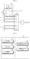
- FIG. 1 is a block diagram showing a functional configuration of a battery management apparatus 100 according to an embodiment of the present disclosure
- FIG. 2 is a circuit diagram showing a functional configuration of a battery pack 1 including the battery management apparatus 100 according to an embodiment of the present disclosure
- FIGS. 3 and 4 are circuit diagrams showing a current path according to an operation state of a first switching element 123.
- the battery pack 1 includes a first input and output terminal P+, a second input and output terminal P-, a first battery module 11, a second battery module 12, a bus bar 20, a contactor 30 and a battery management apparatus 100.
- the first battery module 11 includes a plurality of battery cells C1 1 , ..., C1 n .
- the second battery module 12 includes a plurality of battery cells C2 1 , ..., C2 n .
- the first battery module 11 includes a positive electrode terminal 11a and a negative electrode terminal 11b.
- the second battery module 12 includes a positive electrode terminal 12a and a negative electrode terminal 12b.
- a battery pack according to another embodiment may include at least one battery module. That is, the battery pack according to another embodiment may include one battery module or three or more battery modules.
- the bus bar 20 is installed at a high potential side or a low potential side of the battery pack 1.
- the bus bar 20 is electrically connected to the first input and output terminal P+ or the second input and output terminal P- of the battery pack 1.
- the high potential side may be a high current path between the positive electrode terminal 11a of the first battery module 11 and the first input and output terminal P+
- the low potential side may be a high current path between the negative electrode terminal 12b of the second battery module 12 and the second input and output terminal P-.
- bus bar 20 may be electrically connected to a contactor 30, explained later.
- bus bar 20 may be electrically connected to the contactor 30 installed at the high potential side of the battery pack 1.
- the bus bar 20 may have one end electrically connected to the positive electrode terminal 11a of the first battery module 11 and the other end electrically connected to the contactor 30.
- the contactor 30 is installed at the high potential side or the low potential side of the battery pack 1. An operation state of the contactor 30 is controlled into a turn-on state or a turn-off state according to a switching signal from a processor 130 of the battery management apparatus 100, explained later.
- a pack current may flow through the high current path of the battery pack 1. Meanwhile, while the contactor 30 is in the turn-off state, the flow of the pack current through the high current path of the battery pack 1 is interrupted.
- the battery management apparatus 100 includes a voltage measurement unit 110, a measurement target changing unit 120 and a processor 130.
- the battery management apparatus 100 may further include a communication unit 140.
- the voltage measurement unit 110 is implemented using ASICs (application specific integrated circuits) or the like.
- the voltage measurement unit 110 includes a plurality of measurement channels S 1 , ..., S n+1 respectively electrically connected to the plurality of battery cells C1 1 , ..., C1 n included in the first battery module 11 and measures voltages applied to the plurality of measurement channels S 1 , ..., S n+1 from the plurality of battery cells C1 1 , ..., C1 n , respectively.
- the voltage measurement unit 110 may further include at least one voltage sensor (not shown).
- the plurality of measurement channels S 1 , ..., S n+1 may be electrically connected to the plurality of battery cells C1 1 , ..., C1 n provided in the first battery module 11, respectively. More specifically, among the plurality of measurement channels S 1 , ..., S n+1 , the first measurement channel S 1 is electrically connected to a positive electrode terminal of a battery cell "C1 1 " located at the high potential side among the plurality of battery cells C1 1 , ..., C1 n . Among the plurality of measurement channels S 1 , ..., S n+1 , the second to n th measurement channels S 2 , ..., S n are electrically connected between the battery cells "C1 2 " to "C1 n ", respectively.
- the n+1 th measurement channel S n+1 is electrically connected to a negative electrode terminal of the battery cell "C1 n " located at the low potential side among the plurality of battery cells C1 1 , ..., C1 n .
- the voltage measurement unit 110 may include three measurement channels S 1 , S 2 , S 3 .
- the first measurement channel S 1 is electrically connected to a positive electrode terminal of the battery cell "C1 1 " located at the high potential side among the two battery cells C1 1 , C1 2 .
- the second measurement channel S 2 is electrically connected between the battery cell "C1 2 " and the battery cell "C1 2 ".
- the third measurement channel S 3 is electrically connected to a negative electrode terminal of the battery cell "C1 2 " located at the low potential side among the two battery cells C1 1 , C1 2 .
- a voltage obtained by composing the cell voltages of the plurality of battery cells C1 1 , ..., C1 n may be applied to the first measurement channel S 1 .
- the voltage measurement unit 110 may output a signal indicating the voltage applied to each of the plurality of measurement channels S 1 , ..., S n+1 to the processor 130.
- the measurement target changing unit 120 includes a first measurement line 121, a second measurement line 122 and a first switching element 123.
- the first measurement line 121 electrically connects the positive electrode terminal of the first battery cell C1 1 among the plurality of battery cells C1 1 , ..., C1 n to the first measurement channel S 1 among the plurality of measurement channels S 1 , ..., S n+1 .
- one end of the first measurement line 121 is electrically connected to the positive electrode terminal 11a of the first battery module 11 and thus electrically connected to the positive electrode terminal of the first battery cell C1 1 .
- one end of the first measurement line 121 is electrically connected to one end of the bus bar 20.
- the other end of the first measurement line 121 is electrically connected to the first measurement channel S 1 .
- the second measurement line 122 electrically connects the bus bar 20 to the first measurement channel S 1 .
- one end of the second measurement line 122 is electrically connected to the other end of the bus bar 20.
- the other end of the second measurement line 122 is electrically connected to the first measurement channel S 1 .
- the first switching element 123 electrically connects or disconnects the second measurement line 122. Specifically, the first switching element 123 is installed at the second measurement line 122. The operation state of the first switching element 123 is controlled into a turn-on state or a turn-off state according to the switching signal from the processor 130 of the battery management apparatus 100, explained later.
- the voltage applied to the first measurement channel S 1 may be the voltage of the positive electrode terminal 11a of the first battery module 11, which is equal to the voltage applied to the positive electrode terminal of the first battery cell C1 1 .
- the processor 130 is operably coupled to the voltage measurement unit 110 and the measurement target changing unit 120.
- the processor 130 may also be operably coupled to the contactor 30 and the communication unit 140.
- the processor 130 controls the operation state of the first switching element 123 into a turn-off state.
- the processor 130 calculates a voltage difference between voltages applied to neighboring measurement channel among the plurality of measurement channels S 1 , ..., S n+1 as the cell voltage of each of the plurality of battery cells C1 1 , ..., C1 n . Specifically, the processor 130 calculates a voltage difference of the voltages respectively applied to the n th measurement channel S n and the n+1 th measurement channel S n+1 as the cell voltage of the n th battery cell C1 n .
- n may be a constant of 1 or above.
- the processor 130 calculates a voltage difference of the voltages respectively applied to the second measurement channel S 2 and the third measurement channel S 3 as the cell voltage of the second battery cell C1 2 .
- the processor 130 controls the operation state of the first switching element 123 in order to calculate the cell voltage of the first battery cell C1 1 . Specifically, the processor 130 controls the operation state of the first switching element 123 into a turn-off state and calculates a voltage difference of the voltages respectively applied to the first measurement channel S 1 and the second measurement channel S 2 as the cell voltage of the first battery cell C1 1 .
- the processor 130 controls the operation state of the first switching element 123 into a turn-off state or a turn-on state.
- the processor 130 controls the operation state of the first switching element 123 and calculates the bus bar voltage applied to the bus bar 20 based on the voltage applied to the first measurement channel S 1 and the voltage applied to measurement channels S 2 , ..., S n+1 other than the first measurement channel S 1 among the plurality of measurement channels S 1 , ..., S n+1 .
- the bus bar voltage may be a voltage applied between one end and the other end of the bus bar 20.
- the processor 130 calculates the bus bar voltage after controlling the operation state of the first switching element 123 into a turn-on state.
- the processor 130 calculates the cell voltage of each of battery cells C1 2 , ..., C1 n other than the first battery cell C1 1 among the plurality of battery cells C1 1 , ..., C1 n based on the voltage applied to measurement channels S 2 , ..., S n+1 other than the first measurement channel S 1 .
- the processor 130 calculates a first voltage difference between the voltage applied to the first measurement channel S 1 and the voltage applied to the second measurement channel S 2 electrically connected to the negative electrode terminal of the first battery cell C1 1 .
- the processor 130 calculates a bus bar voltage by using the calculated first voltage difference and the cell voltage.
- the processor 130 calculates a cell voltage average of the cell voltages of the battery cells C1 2 , ..., C1 n other than the first battery cell C1 1 , and calculates a voltage difference between the first voltage difference and the cell voltage average as the bus bar voltage.
- the processor 130 controls the first switching element 123 into a turn-on state, as shown in FIG. 3 , a voltage obtained by composing the cell voltage of each of all battery cells C1 1 , ..., C1 n and the bus bar voltage applied to the bus bar 20 is applied to the first measurement channel S 1 , and a voltage obtained by composing the cell voltages of the battery cells C1 2 , ..., C1 n other than the first battery cell C1 1 is applied to the second measurement channel S 2 . Accordingly, in a state where the operation state of the first switching element 123 is controlled into a turn-on state, the first voltage difference calculated by the processor 130 may be a voltage obtained by composing the cell voltage of the first battery cell C1 1 and the bus bar voltage.
- the cell voltage average of the cell voltages of the battery cells C1 2 , ..., C1 n other than the first battery cell C1 1 may be estimated as the cell voltage of the first battery cell C1 1 .
- the processor 130 calculates a voltage difference between the first voltage difference and the cell voltage average as the bus bar voltage.
- a battery management apparatus may be different from the battery management apparatus 100 according to an embodiment of the present disclosure only in the process where a processor 130' calculates a bus bar voltage.
- the processor 130' may calculate a bus bar voltage by using the second voltage difference between the voltage applied to the first measurement channel S 1 after the operation state of the first switching element 123 is controlled into a turn-on state and the voltage applied to the first measurement channel S 1 before the operation state of the first switching element 123 is controlled into a turn-on state.
- the processor 130' stores the voltage applied to the first measurement channel S 1 before the operation state of the first switching element 123 is controlled into a turn-on state. That is, the processor 130' according to another embodiment stores the voltage applied to the first measurement channel S 1 when the operation state of the first switching element 123 is a turn-off state.
- the processor 130' controls the operation state of the first switching element 123 into a turn-on state and stores the voltage applied to the first measurement channel S 1 when the operation state of the first switching element 123 is a turn-on state.
- the processor 130' controls the first switching element 123 into a turn-on state, as shown in FIG. 3 , a voltage obtained by composing the cell voltage of each of all battery cells C1 1 , ..., C1 n and the bus bar voltage applied to the bus bar 20 is applied to the first measurement channel S 1 .
- the processor 130' controls the first switching element 123 into a turn-off state as shown in FIG. 4 , a voltage obtained by composing only the cell voltages of all battery cells C1 1 , ..., C1 n is applied to the first measurement channel S 1 .
- the processor 130' may calculates the second voltage difference between the voltage applied to the first measurement channel S 1 after the operation state of the first switching element 123 is controlled into a turn-on state and the voltage applied to the first measurement channel S 1 before the operation state of the first switching element 123 is controlled into a turn-on state as the bus bar voltage.
- any one measurement channel among the measurement channels of the voltage measurement unit 110 for measuring the cell voltage of each of the plurality of battery cells included in the battery module it is possible to measure the bus bar voltage by utilizing the voltage measurement unit 110 having a limited number of measurement channels.
- the processor 130, 130' may be is implemented in hardware by using at least one of application specific integrated circuits (ASICs), digital signal processors (DSPs), digital signal processing devices (DSPDs), programmable logic devices (PLDs), field programmable gate arrays (FPGAs), microcontrollers, and electrical units for performing other functions.
- ASICs application specific integrated circuits
- DSPs digital signal processors
- DSPDs digital signal processing devices
- PLDs programmable logic devices
- FPGAs field programmable gate arrays
- microcontrollers and electrical units for performing other functions.
- the processor 130, 130' may have a built-in memory. In the memory, a program for executing a method explained later and various data may be stored.
- the memory may include, for example, at least type of storage media selected from a flash memory type, a hard disk type, a solid state disk (SSD) type, a silicon disk drive type, a multimedia card micro type, a random access memory (RAM), a static random access memory (SRAM), a read-only memory (ROM), an electrically erasable programmable read-only memory (EEPROM), and a programmable read-only memory (PROM).
- a flash memory type a hard disk type, a solid state disk (SSD) type, a silicon disk drive type, a multimedia card micro type, a random access memory (RAM), a static random access memory (SRAM), a read-only memory (ROM), an electrically erasable programmable read-only memory (EEPROM), and a programmable read-only memory (PROM).
- the communication unit 140 is configured to support bidirectional communication between the processor 130 and an external device 2.
- the communication unit 140 may transmit a message indicating the bus bar voltage calculated by the processor 130 to the external device 2.
- the communication unit 140 may transmit a command from the external device 2 to the processor 130.
- FIG. 5 is a block diagram showing a functional configuration of a battery management apparatus 100" according to still another embodiment of the present disclosure
- FIG. 6 is a circuit diagram showing a functional configuration of a battery pack 1 including the battery management apparatus 100" according to still another embodiment of the present disclosure
- FIG. 7 is a circuit diagram showing a current path according to operation states of a first switching element 123 and a second switching element 124".
- a battery management apparatus 100" according to still another embodiment of the present disclosure is different from the battery management apparatus 100 according to an embodiment of the present disclosure in the point that the configuration of the measurement target changing unit 120" and the role of the processor 130" are partially different and a current measurement unit 150" is further included. Except for them, the components included in the battery management apparatus 100" according to still another embodiment of the present disclosure and their roles may be identical to those of the battery management apparatus 100 according to an embodiment of the present disclosure. Thus, repeated explanations will be omitted.
- the measurement target changing unit 120" of the battery management apparatus 100" includes a first measurement line 121, a second measurement line 122, a first switching element 123 and a second switching element 124".
- the second switching element 124" electrically connects or disconnects the first measurement line 121. Specifically, the second switching element 124" is installed to the first measurement line 121. The operation state of the second switching element 124" is controlled into a turn-on state or a turn-off state according to a switching signal from the processor 130".
- the processor 130" may calculate the bus bar voltage of the bus bar 20 in the same way as the processor 130 according to an embodiment and the processor 130' according to another embodiment.
- the processor 130" according to still another embodiment further controls the second switching element 124" in addition to the first switching element 123, and thus the bus bar voltage of the bus bar 20 may be calculated using at least one of the voltages applied to the plurality of plurality of measurement channels S 1 , ..., S n+1 of the voltage measurement unit 110.
- the current measurement unit 150" measures a pack current flowing through the high current path of the battery pack 1.
- the current measurement unit 150" may be installed between the negative electrode terminal 12b of the second battery module 12 and the second input and output terminal P-.
- the current measurement unit 150" may also be installed between the positive electrode terminal 11a of the first battery module 11 and the first input and output terminal P+.
- the current measurement unit 150" outputs a current signal indicating the measured pack current to the processor 130".
- the processor 130" diagnoses whether a failure occurs at the bus bar 20, based on the calculated bus bar voltage and the measured pack current.
- the processor 130" calculates a bus bar resistance of the bus bar 20 by using the calculated bus bar voltage and the measured pack current, and diagnoses whether a failure occurs at the bus bar 20 by comparing the calculated bus bar resistance with a reference resistance.
- the processor 130" calculates the bus bar resistance by using Equation 1 below.
- R b V b / I p
- R b is a bus bar resistance
- V b is a bus bar voltage
- I p is a pack current
- the processor 130" diagnoses that a failure occurs at the bus bar 20 if the calculated bus bar resistance is greater than the reference resistance. On the contrary, the processor 130" according to still another embodiment diagnoses that a failure does not occur at the bus bar 20 if the calculated bus bar resistance is smaller than the reference resistance.
- the failure may mean a state where a crack is generated at the bus bar 20 or the bus bar 20 is separated from a pack case of the battery pack 1 without being closely attached thereto.
- the processor 130" controls the operation state of at least one of the first switching element 123 and the second switching element 124" based on the diagnosing result on whether a failure occurs at the bus bar 20.
- the processor 130" controls the operation states of the first switching element 123 and the second switching element 124" into a turn-off state. Accordingly, as shown in FIG. 7 , the bus bar voltage may not be applied to the first measurement channel S 1 of the voltage measurement unit 110.
- the processor 130" does not control the operation states of both of the first switching element 123 and the second switching element 124" into a turn-off state.
- the operation states of the first switching element 123 and the second switching element 124" are controlled into a turn-off state, thereby preventing a phenomenon that a high voltage applied to the bus bar 20 is applied to the first measurement channel S 1 of the voltage measurement unit 110 as a failure occurs to increase the resistance.
- the communication unit 140 may transmit a diagnosis message indicating the diagnosing result from the processor 130" to the external device 2.
- the embodiments of the present disclosure described above may not be implemented only through an apparatus and a method, but may be implemented through a program that realizes a function corresponding to the configuration of the embodiments of the present disclosure or a recording medium on which the program is recorded.
- the program or recording medium may be easily implemented by those skilled in the art from the above description of the embodiments.
Landscapes
- Physics & Mathematics (AREA)
- General Physics & Mathematics (AREA)
- Chemical & Material Sciences (AREA)
- Chemical Kinetics & Catalysis (AREA)
- Electrochemistry (AREA)
- General Chemical & Material Sciences (AREA)
- Engineering & Computer Science (AREA)
- Manufacturing & Machinery (AREA)
- Microelectronics & Electronic Packaging (AREA)
- Mechanical Engineering (AREA)
- Power Engineering (AREA)
- Secondary Cells (AREA)
- Testing Of Short-Circuits, Discontinuities, Leakage, Or Incorrect Line Connections (AREA)
- Tests Of Electric Status Of Batteries (AREA)
- Charge And Discharge Circuits For Batteries Or The Like (AREA)
- Battery Mounting, Suspending (AREA)
- Connection Of Batteries Or Terminals (AREA)
Abstract
Description
- The present application claims priority to Korean Patent Application No.
10-2018-0107983 filed on September 10, 2018 - The present disclosure relates to a battery management apparatus, and more particularly, to a battery management apparatus for monitoring a state of a bus bar installed to an input and output terminal of a battery pack.
- Recently, as the demand for portable electronic products such as laptops, video cameras, mobile phones, and the like is rapidly increased and the development of electric vehicles, storage batteries for energy storage, robots, satellites, and the like is in earnest, high-performance batteries capable of repeatedly charging and discharging is actively studied.
- Batteries currently commercialized include nickel cadmium batteries, nickel hydride batteries, nickel zinc batteries, and lithium batteries. Among them, the lithium batteries have almost no memory effect compared to nickel-based batteries, to freely charge and discharge, and have a very low high self-discharge rate and a high energy density. Thus, lithium batteries have attracted much attention.
- Recently, in order to provide a high voltage, the demand for a battery pack including two or more battery modules connected in series through a bus bar and having bus bars installed at input and output terminals for charging and discharging has increased. One end of the bus bar installed between the battery modules is connected to a positive electrode terminal of one battery module and the other end of the bus bar is connected to a negative electrode terminal of the other battery module, thus providing a current path through the two battery modules. In addition, one of the bus bars installed to the input and output terminals of the battery pack is connected to a positive electrode terminal of the battery module having the highest potential, and the other bus bar is connected to a negative electrode terminal of the battery module having the lowest potential.
- However, due to an external shock or aging of the bus bar itself, the connection state between the bus bar and the battery module may become worse. For example, if a crack occurs in the bus bar or the contact area between one end of the bus bar and the terminal of the battery module decreases, the resistance of the current path between the two battery modules may increase, causing serious heat generation. In a severe case, the two battery modules may be completely electrically disconnected.
- Accordingly, there is an increasing need for a technique of properly diagnosing a failure of the bus bar that that provides a current path between two battery modules and to the input and output terminal of the battery pack.
- To this end, the conventional bus bar diagnosis device electrically connects the bus bar to measurement channels of a voltage measurement unit to measure a voltage of the bus bar and diagnoses a failure of the bus bar using the measured voltage of the bus bar.
- In this case, some of the measurement channels of the voltage measurement unit for measuring a voltage of each of a plurality of battery modules, a voltage of a plurality of battery cells included in each of the battery modules, or the like should be used for measuring the voltage of the bus bar.
- Accordingly, the conventional bus bar diagnosis device must include a plurality of voltage measurement units to increase the number of measurement channels in order to measure the voltages of the plurality of battery modules and the plurality of battery cells and further measure the voltage of the bus bar.
- The present disclosure is designed to solve the problems of the related art, and therefore the present disclosure is directed to providing a battery management apparatus capable of measuring a voltage of a bus bar installed to an input and output terminal of a battery pack by using a measurement channel of a voltage measurement unit for measuring a cell voltage of a battery cell.
- In addition, the present disclosure is directed to providing a battery management apparatus capable of diagnosing a failure of the bus bar based on the voltage of the bus bar and the cell voltage of the battery cell.
- These and other objects and advantages of the present disclosure may be understood from the following detailed description and will become more fully apparent from the exemplary embodiments of the present disclosure. Also, it will be easily understood that the objects and advantages of the present disclosure may be realized by the means shown in the appended claims and combinations thereof.
- Various embodiments of the present disclosure for accomplishing the above objects are as follows.
- A battery management apparatus according to the present disclosure monitors a state of a bus bar electrically connected to an input and output terminal of a battery pack including at least one battery module.
- The battery management apparatus comprises: a voltage measurement unit having a plurality of measurement channels respectively electrically connected to a plurality of battery cells included in the battery module and configured to measure voltages applied to the plurality of measurement channels; a measurement target changing unit having a first measurement line for electrically connecting a positive electrode terminal of a first battery cell among the plurality of battery cells to a first measurement channel among the plurality of measurement channels, a second measurement line for electrically connecting the bus bar to the first measurement channel, and a first switching element for electrically connecting or disconnecting the second measurement line; and a processor configured to control an operation state of the first switching element and calculate a bus bar voltage applied to the bus bar based on a voltage applied to the first measurement channel and a voltage applied to a measurement channel other than the first measurement channel among the plurality of measurement channels.
- The processor may control the operation state of the first switching element into a turn-on state and calculate the bus bar voltage.
- After the operation state of the first switching element is controlled into a turn-on state, the processor may calculate a cell voltage of each of battery cells other than the first battery cell among the plurality of battery cells based on the voltage applied to the measurement channel other than the first measurement channel, calculate a first voltage difference between the voltage applied to the first measurement channel and a voltage applied to a second measurement channel electrically connected to a negative electrode terminal of the first battery cell, and calculate the bus bar voltage by using the first voltage difference and the cell voltage.
- The processor may calculate the bus bar voltage by using a second voltage difference between the voltage applied to the first measurement channel after the operation state of the first switching element is controlled into a turn-on state and the voltage applied to the first measurement channel before the operation state of the first switching element is controlled into a turn-on state.
- The processor may control the operation state of the first switching element into a turn-off state, when a cell voltage measurement request signal requesting to measure a cell voltage of each of the plurality of battery cells is received.
- After the operation state of the first switching element is controlled into a turn-off state, the processor may calculate a second voltage difference between the voltage applied to the first measurement channel and a voltage applied to a second measurement channel electrically connected to a negative electrode terminal of the first battery cell as the cell voltage of the first battery cell.
- The battery management apparatus may further comprise a current measurement unit configured to measure a pack current flowing at the input and output terminal of the battery pack.
- The measurement target changing unit may include a second switching element configured to electrically connect or disconnect the first measurement line.
- The processor may diagnose whether a failure occurs at the bus bar based on the pack current and the bus bar voltage and control an operation state of at least one of the first switching element and the second switching element based on the diagnosing result.
- When it is diagnosed that a failure occurs at the bus bar, the processor may control the operation states of the first switching element and the second switching element into a turn-off state.
- A battery pack according to the present disclosure comprises the battery management apparatus.
- A vehicle according to the present disclosure comprises the battery management apparatus.
- According to at least one of the embodiments of the present disclosure, since a voltage of a bus bar installed to an input and output terminal of a battery pack is measured using a measurement channel of a voltage measurement unit for measuring a cell voltage of a battery cell, it is possible to decrease the number of measurement channels that must be provided in the voltage measurement unit.
- In addition, according to at least one of the embodiments of the present disclosure, it is possible to suitably diagnose a failure of the bus bar installed to the input and output terminal of the battery pack.
- The effects of the present disclosure are not limited to the effects mentioned above, and other effects not mentioned will be clearly understood by those skilled in the art from the description of the claims.
- The accompanying drawings illustrate a preferred embodiment of the present disclosure and together with the foregoing disclosure, serve to provide further understanding of the technical features of the present disclosure, and thus, the present disclosure is not construed as being limited to the drawing.
-
FIG. 1 is a block diagram showing a functional configuration of a battery management apparatus according to an embodiment of the present disclosure. -
FIG. 2 is a circuit diagram showing a functional configuration of a battery pack including the battery management apparatus according to an embodiment of the present disclosure. -
FIGS. 3 and4 are circuit diagrams showing a current path according to an operation state of a first switching element. -
FIG. 5 is a block diagram showing a functional configuration of a battery management apparatus according to still another embodiment of the present disclosure. -
FIG. 6 is a circuit diagram showing a functional configuration of a battery pack including the battery management apparatus according to still another embodiment of the present disclosure. -
FIG. 7 is a circuit diagram showing a current path according to operation states of a first switching element and a second switching element. - Hereinafter, preferred embodiments of the present disclosure will be described in detail with reference to the accompanying drawings. Prior to the description, it should be understood that the terms used in the specification and the appended claims should not be construed as limited to general and dictionary meanings, but interpreted based on the meanings and concepts corresponding to technical aspects of the present disclosure on the basis of the principle that the inventor is allowed to define terms appropriately for the best explanation.
- Therefore, the description proposed herein is just a preferable example for the purpose of illustrations only, not intended to limit the scope of the disclosure, so it should be understood that other equivalents and modifications could be made thereto without departing from the scope of the disclosure.
- In addition, in describing the present disclosure, if it is determined that detailed description of a related configuration or function may obscure the gist of the present disclosure, the detailed description will be omitted.
- Terms including ordinal numbers, such as first and second, are used for the purpose of distinguishing any one of various components from the others, and are not used to limit the components by the terms.
- Throughout the specification, when a part "includes" a certain component, it means that the part may further include other components, without excluding other components, unless otherwise stated.
- In addition, throughout the specification, when a part is "connected" to another part, this includes not only the case where these parts are "directly connected" but also the case where these parts are "indirectly connected" with another element being interposed therebetween.
-
FIG. 1 is a block diagram showing a functional configuration of abattery management apparatus 100 according to an embodiment of the present disclosure,FIG. 2 is a circuit diagram showing a functional configuration of abattery pack 1 including thebattery management apparatus 100 according to an embodiment of the present disclosure, andFIGS. 3 and4 are circuit diagrams showing a current path according to an operation state of afirst switching element 123. - Referring to
FIGS. 1 to 4 , thebattery pack 1 includes a first input and output terminal P+, a second input and output terminal P-, a first battery module 11, asecond battery module 12, abus bar 20, acontactor 30 and abattery management apparatus 100. - The first battery module 11 includes a plurality of battery cells C11, ..., C1n. The
second battery module 12 includes a plurality of battery cells C21, ..., C2n. The first battery module 11 includes apositive electrode terminal 11a and anegative electrode terminal 11b. Thesecond battery module 12 includes apositive electrode terminal 12a and anegative electrode terminal 12b. - Even though it is described that the
battery pack 1 according to an embodiment of the present disclosure includes two battery modules, a battery pack according to another embodiment may include at least one battery module. That is, the battery pack according to another embodiment may include one battery module or three or more battery modules. - The
bus bar 20 is installed at a high potential side or a low potential side of thebattery pack 1. Thebus bar 20 is electrically connected to the first input and output terminal P+ or the second input and output terminal P- of thebattery pack 1. Here, the high potential side may be a high current path between thepositive electrode terminal 11a of the first battery module 11 and the first input and output terminal P+, and the low potential side may be a high current path between thenegative electrode terminal 12b of thesecond battery module 12 and the second input and output terminal P-. - In addition, the
bus bar 20 may be electrically connected to acontactor 30, explained later. - For example, the
bus bar 20 may be electrically connected to thecontactor 30 installed at the high potential side of thebattery pack 1. - That is, the
bus bar 20 may have one end electrically connected to thepositive electrode terminal 11a of the first battery module 11 and the other end electrically connected to thecontactor 30. - The
contactor 30 is installed at the high potential side or the low potential side of thebattery pack 1. An operation state of thecontactor 30 is controlled into a turn-on state or a turn-off state according to a switching signal from aprocessor 130 of thebattery management apparatus 100, explained later. - While the
contactor 30 is in the turn-on state, a pack current may flow through the high current path of thebattery pack 1. Meanwhile, while thecontactor 30 is in the turn-off state, the flow of the pack current through the high current path of thebattery pack 1 is interrupted. - The
battery management apparatus 100 includes avoltage measurement unit 110, a measurementtarget changing unit 120 and aprocessor 130. Thebattery management apparatus 100 may further include acommunication unit 140. - The
voltage measurement unit 110 is implemented using ASICs (application specific integrated circuits) or the like. Thevoltage measurement unit 110 includes a plurality of measurement channels S1, ..., Sn+1 respectively electrically connected to the plurality of battery cells C11, ..., C1n included in the first battery module 11 and measures voltages applied to the plurality of measurement channels S1, ..., Sn+1 from the plurality of battery cells C11, ..., C1n, respectively. - For this, the
voltage measurement unit 110 may further include at least one voltage sensor (not shown). - The plurality of measurement channels S1, ..., Sn+1 may be electrically connected to the plurality of battery cells C11, ..., C1n provided in the first battery module 11, respectively. More specifically, among the plurality of measurement channels S1, ..., Sn+1, the first measurement channel S1 is electrically connected to a positive electrode terminal of a battery cell "C11" located at the high potential side among the plurality of battery cells C11, ..., C1n. Among the plurality of measurement channels S1, ..., Sn+1, the second to nth measurement channels S2, ..., Sn are electrically connected between the battery cells "C12" to "C1n", respectively. Among the plurality of measurement channels S1, ..., Sn+1, the n+1th measurement channel Sn+1 is electrically connected to a negative electrode terminal of the battery cell "C1n" located at the low potential side among the plurality of battery cells C11, ..., C1n.
- For example, if the first battery module 11 includes two battery cells C11, C12, the
voltage measurement unit 110 may include three measurement channels S1, S2, S3. At this time, among the three measurement channels S1, S2, S3, the first measurement channel S1 is electrically connected to a positive electrode terminal of the battery cell "C11" located at the high potential side among the two battery cells C11, C12. Among the three measurement channels S1, S2, S3, the second measurement channel S2 is electrically connected between the battery cell "C12" and the battery cell "C12". Among the three measurement channels S1, S2, S3, the third measurement channel S3 is electrically connected to a negative electrode terminal of the battery cell "C12" located at the low potential side among the two battery cells C11, C12. - Accordingly, a voltage obtained by composing the cell voltages of the plurality of battery cells C11, ..., C1n may be applied to the first measurement channel S1.
- The
voltage measurement unit 110 may output a signal indicating the voltage applied to each of the plurality of measurement channels S1, ..., Sn+1 to theprocessor 130. - The measurement
target changing unit 120 includes afirst measurement line 121, asecond measurement line 122 and afirst switching element 123. - The
first measurement line 121 electrically connects the positive electrode terminal of the first battery cell C11 among the plurality of battery cells C11, ..., C1n to the first measurement channel S1 among the plurality of measurement channels S1, ..., Sn+1. For this, one end of thefirst measurement line 121 is electrically connected to thepositive electrode terminal 11a of the first battery module 11 and thus electrically connected to the positive electrode terminal of the first battery cell C11. In addition, one end of thefirst measurement line 121 is electrically connected to one end of thebus bar 20. The other end of thefirst measurement line 121 is electrically connected to the first measurement channel S1. - The
second measurement line 122 electrically connects thebus bar 20 to the first measurement channel S1. For this, one end of thesecond measurement line 122 is electrically connected to the other end of thebus bar 20. The other end of thesecond measurement line 122 is electrically connected to the first measurement channel S1. - The
first switching element 123 electrically connects or disconnects thesecond measurement line 122. Specifically, thefirst switching element 123 is installed at thesecond measurement line 122. The operation state of thefirst switching element 123 is controlled into a turn-on state or a turn-off state according to the switching signal from theprocessor 130 of thebattery management apparatus 100, explained later. - While the
first switching element 123 is in the turn-on state, a current does not flow through thefirst measurement line 121 but a current flows through thesecond measurement line 122, so that the voltage applied to the other end of thebus bar 20 is applied to the first measurement channel S1. - On the contrary, while the
first switching element 123 is in the turn-off state, a current is interrupted to thesecond measurement line 122 and a current flows through thefirst measurement line 121, so that the voltage of the positive electrode terminal of the first battery cell C11 is applied to the first measurement channel S1. Here, while thefirst switching element 123 is in the turn-off state, the voltage applied to the first measurement channel S1 may be the voltage of thepositive electrode terminal 11a of the first battery module 11, which is equal to the voltage applied to the positive electrode terminal of the first battery cell C11. - The
processor 130 is operably coupled to thevoltage measurement unit 110 and the measurementtarget changing unit 120. Theprocessor 130 may also be operably coupled to thecontactor 30 and thecommunication unit 140. - If a cell voltage measurement request signal requesting to measure a cell voltage of each of the plurality of battery cells C11, ..., C1n is received, the
processor 130 controls the operation state of thefirst switching element 123 into a turn-off state. - After that, the
processor 130 calculates a voltage difference between voltages applied to neighboring measurement channel among the plurality of measurement channels S1, ..., Sn+1 as the cell voltage of each of the plurality of battery cells C11, ..., C1n. Specifically, theprocessor 130 calculates a voltage difference of the voltages respectively applied to the nth measurement channel Sn and the n+1th measurement channel Sn+1 as the cell voltage of the nth battery cell C1n. Here, n may be a constant of 1 or above. For example, theprocessor 130 calculates a voltage difference of the voltages respectively applied to the second measurement channel S2 and the third measurement channel S3 as the cell voltage of the second battery cell C12. - At this time, the
processor 130 controls the operation state of thefirst switching element 123 in order to calculate the cell voltage of the first battery cell C11. Specifically, theprocessor 130 controls the operation state of thefirst switching element 123 into a turn-off state and calculates a voltage difference of the voltages respectively applied to the first measurement channel S1 and the second measurement channel S2 as the cell voltage of the first battery cell C11. - Meanwhile, a bus bar voltage measurement request signal requesting to measure a bus bar voltage of the
bus bar 20 is received, theprocessor 130 controls the operation state of thefirst switching element 123 into a turn-off state or a turn-on state. - The
processor 130 controls the operation state of thefirst switching element 123 and calculates the bus bar voltage applied to thebus bar 20 based on the voltage applied to the first measurement channel S1 and the voltage applied to measurement channels S2, ..., Sn+1 other than the first measurement channel S1 among the plurality of measurement channels S1, ..., Sn+1. Here, the bus bar voltage may be a voltage applied between one end and the other end of thebus bar 20. - The
processor 130 calculates the bus bar voltage after controlling the operation state of thefirst switching element 123 into a turn-on state. - Specifically, after the operation state of the
first switching element 123 is controlled into a turn-on state, theprocessor 130 calculates the cell voltage of each of battery cells C12, ..., C1n other than the first battery cell C11 among the plurality of battery cells C11, ..., C1n based on the voltage applied to measurement channels S2, ..., Sn+1 other than the first measurement channel S1. - After that, in a state where the operation state of the
first switching element 123 is controlled into a turn-on state, theprocessor 130 calculates a first voltage difference between the voltage applied to the first measurement channel S1 and the voltage applied to the second measurement channel S2 electrically connected to the negative electrode terminal of the first battery cell C11. - Next, the
processor 130 calculates a bus bar voltage by using the calculated first voltage difference and the cell voltage. - At this time, the
processor 130 calculates a cell voltage average of the cell voltages of the battery cells C12, ..., C1n other than the first battery cell C11, and calculates a voltage difference between the first voltage difference and the cell voltage average as the bus bar voltage. - If the
processor 130 controls thefirst switching element 123 into a turn-on state, as shown inFIG. 3 , a voltage obtained by composing the cell voltage of each of all battery cells C11, ..., C1n and the bus bar voltage applied to thebus bar 20 is applied to the first measurement channel S1, and a voltage obtained by composing the cell voltages of the battery cells C12, ..., C1n other than the first battery cell C11 is applied to the second measurement channel S2. Accordingly, in a state where the operation state of thefirst switching element 123 is controlled into a turn-on state, the first voltage difference calculated by theprocessor 130 may be a voltage obtained by composing the cell voltage of the first battery cell C11 and the bus bar voltage. - Meanwhile, since the cell voltages of the plurality of battery cells C11, ..., C1n included in the same battery module have a predetermined voltage difference, the cell voltage average of the cell voltages of the battery cells C12, ..., C1n other than the first battery cell C11 may be estimated as the cell voltage of the first battery cell C11.
- By using this, the
processor 130 calculates a voltage difference between the first voltage difference and the cell voltage average as the bus bar voltage. - A battery management apparatus according to another embodiment of the present disclosure may be different from the
battery management apparatus 100 according to an embodiment of the present disclosure only in the process where a processor 130' calculates a bus bar voltage. - Specifically, the processor 130' according to another embodiment may calculate a bus bar voltage by using the second voltage difference between the voltage applied to the first measurement channel S1 after the operation state of the
first switching element 123 is controlled into a turn-on state and the voltage applied to the first measurement channel S1 before the operation state of thefirst switching element 123 is controlled into a turn-on state. - Specifically, if a bus bar voltage measurement request signal is received, the processor 130' according to another embodiment stores the voltage applied to the first measurement channel S1 before the operation state of the
first switching element 123 is controlled into a turn-on state. That is, the processor 130' according to another embodiment stores the voltage applied to the first measurement channel S1 when the operation state of thefirst switching element 123 is a turn-off state. - After that, the processor 130' according to another embodiment controls the operation state of the
first switching element 123 into a turn-on state and stores the voltage applied to the first measurement channel S1 when the operation state of thefirst switching element 123 is a turn-on state. - As described above, if the processor 130' controls the
first switching element 123 into a turn-on state, as shown inFIG. 3 , a voltage obtained by composing the cell voltage of each of all battery cells C11, ..., C1n and the bus bar voltage applied to thebus bar 20 is applied to the first measurement channel S1. On the contrary, if the processor 130' controls thefirst switching element 123 into a turn-off state, as shown inFIG. 4 , a voltage obtained by composing only the cell voltages of all battery cells C11, ..., C1n is applied to the first measurement channel S1. - By using this, the processor 130' according to another embodiment may calculates the second voltage difference between the voltage applied to the first measurement channel S1 after the operation state of the
first switching element 123 is controlled into a turn-on state and the voltage applied to the first measurement channel S1 before the operation state of thefirst switching element 123 is controlled into a turn-on state as the bus bar voltage. - According to the present disclosure, by using any one measurement channel among the measurement channels of the
voltage measurement unit 110 for measuring the cell voltage of each of the plurality of battery cells included in the battery module, it is possible to measure the bus bar voltage by utilizing thevoltage measurement unit 110 having a limited number of measurement channels. - The
processor 130, 130' may be is implemented in hardware by using at least one of application specific integrated circuits (ASICs), digital signal processors (DSPs), digital signal processing devices (DSPDs), programmable logic devices (PLDs), field programmable gate arrays (FPGAs), microcontrollers, and electrical units for performing other functions. Theprocessor 130, 130' may have a built-in memory. In the memory, a program for executing a method explained later and various data may be stored. The memory may include, for example, at least type of storage media selected from a flash memory type, a hard disk type, a solid state disk (SSD) type, a silicon disk drive type, a multimedia card micro type, a random access memory (RAM), a static random access memory (SRAM), a read-only memory (ROM), an electrically erasable programmable read-only memory (EEPROM), and a programmable read-only memory (PROM). - The
communication unit 140 is configured to support bidirectional communication between theprocessor 130 and anexternal device 2. Thecommunication unit 140 may transmit a message indicating the bus bar voltage calculated by theprocessor 130 to theexternal device 2. Thecommunication unit 140 may transmit a command from theexternal device 2 to theprocessor 130. - Hereinafter, a
battery management apparatus 100" according to still another embodiment will be described. -
FIG. 5 is a block diagram showing a functional configuration of abattery management apparatus 100" according to still another embodiment of the present disclosure,FIG. 6 is a circuit diagram showing a functional configuration of abattery pack 1 including thebattery management apparatus 100" according to still another embodiment of the present disclosure, andFIG. 7 is a circuit diagram showing a current path according to operation states of afirst switching element 123 and asecond switching element 124". - Referring to
FIGS. 5 to 7 , abattery management apparatus 100" according to still another embodiment of the present disclosure is different from thebattery management apparatus 100 according to an embodiment of the present disclosure in the point that the configuration of the measurementtarget changing unit 120" and the role of theprocessor 130" are partially different and acurrent measurement unit 150" is further included. Except for them, the components included in thebattery management apparatus 100" according to still another embodiment of the present disclosure and their roles may be identical to those of thebattery management apparatus 100 according to an embodiment of the present disclosure. Thus, repeated explanations will be omitted. - The measurement
target changing unit 120" of thebattery management apparatus 100" according to still another embodiment of the present disclosure includes afirst measurement line 121, asecond measurement line 122, afirst switching element 123 and asecond switching element 124". - The
second switching element 124" electrically connects or disconnects thefirst measurement line 121. Specifically, thesecond switching element 124" is installed to thefirst measurement line 121. The operation state of thesecond switching element 124" is controlled into a turn-on state or a turn-off state according to a switching signal from theprocessor 130". - At this time, while the
second switching element 124" is in a turn-off state and thefirst switching element 123 is in a turn-on state, a current does not flow through thefirst measurement line 121 but a current flows through thesecond measurement line 122, so that a voltage applied to the other end of thebus bar 20 is applied to the first measurement channel S1. - In addition, while the
second switching element 124" is in a turn-on state and thefirst switching element 123 is in a turn-off state, a current is interrupted to thesecond measurement line 122 and a current flows through thefirst measurement line 121, so that the voltage of the positive electrode terminal of the first battery cell C11 is applied to the first measurement channel S1. - Also, while the
second switching element 124" and thefirst switching element 123 are in a turn-off state, a current is interrupted to thefirst measurement line 121 and thesecond measurement line 122, so that a voltage is not applied to the first measurement channel S1. - The
processor 130" according to still another embodiment may calculate the bus bar voltage of thebus bar 20 in the same way as theprocessor 130 according to an embodiment and the processor 130' according to another embodiment. - However, the
processor 130" according to still another embodiment further controls thesecond switching element 124" in addition to thefirst switching element 123, and thus the bus bar voltage of thebus bar 20 may be calculated using at least one of the voltages applied to the plurality of plurality of measurement channels S1, ..., Sn+1 of thevoltage measurement unit 110. - The
current measurement unit 150" measures a pack current flowing through the high current path of thebattery pack 1. For example, as shown in the figures, thecurrent measurement unit 150" may be installed between thenegative electrode terminal 12b of thesecond battery module 12 and the second input and output terminal P-. Here, thecurrent measurement unit 150" may also be installed between thepositive electrode terminal 11a of the first battery module 11 and the first input and output terminal P+. Thecurrent measurement unit 150" outputs a current signal indicating the measured pack current to theprocessor 130". - The
processor 130" according to still another embodiment diagnoses whether a failure occurs at thebus bar 20, based on the calculated bus bar voltage and the measured pack current. - Specifically, the
processor 130" according to still another embodiment calculates a bus bar resistance of thebus bar 20 by using the calculated bus bar voltage and the measured pack current, and diagnoses whether a failure occurs at thebus bar 20 by comparing the calculated bus bar resistance with a reference resistance. - At this time, the
processor 130" according to still another embodiment calculates the bus bar resistance by usingEquation 1 below.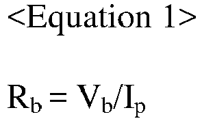
- Here, Rb is a bus bar resistance, Vb is a bus bar voltage, and Ip is a pack current.
- The
processor 130" according to still another embodiment diagnoses that a failure occurs at thebus bar 20 if the calculated bus bar resistance is greater than the reference resistance. On the contrary, theprocessor 130" according to still another embodiment diagnoses that a failure does not occur at thebus bar 20 if the calculated bus bar resistance is smaller than the reference resistance. - Here, the failure may mean a state where a crack is generated at the
bus bar 20 or thebus bar 20 is separated from a pack case of thebattery pack 1 without being closely attached thereto. - The
processor 130" according to still another embodiment controls the operation state of at least one of thefirst switching element 123 and thesecond switching element 124" based on the diagnosing result on whether a failure occurs at thebus bar 20. - Specifically, if it is diagnosed that a failure occurs at the
bus bar 20, theprocessor 130" according to still another embodiment controls the operation states of thefirst switching element 123 and thesecond switching element 124" into a turn-off state. Accordingly, as shown inFIG. 7 , the bus bar voltage may not be applied to the first measurement channel S1 of thevoltage measurement unit 110. - On the contrary, if it is diagnosed that a failure does not occur at the
bus bar 20, theprocessor 130" according to still another embodiment does not control the operation states of both of thefirst switching element 123 and thesecond switching element 124" into a turn-off state. - According to the present disclosure, if a failure does not occur at the
bus bar 20, the operation states of thefirst switching element 123 and thesecond switching element 124" are controlled into a turn-off state, thereby preventing a phenomenon that a high voltage applied to thebus bar 20 is applied to the first measurement channel S1 of thevoltage measurement unit 110 as a failure occurs to increase the resistance. - The
communication unit 140 may transmit a diagnosis message indicating the diagnosing result from theprocessor 130" to theexternal device 2. - The embodiments of the present disclosure described above may not be implemented only through an apparatus and a method, but may be implemented through a program that realizes a function corresponding to the configuration of the embodiments of the present disclosure or a recording medium on which the program is recorded. The program or recording medium may be easily implemented by those skilled in the art from the above description of the embodiments.
- The present disclosure has been described in detail. However, it should be understood that the detailed description and specific examples, while indicating preferred embodiments of the disclosure, are given by way of illustration only, since various changes and modifications within the scope of the disclosure will become apparent to those skilled in the art from this detailed description.
- In addition, since the present disclosure described above can be substituted, modified and changed in various ways by those skilled in the art without departing from the technical idea of the present disclosure, the present disclosure is not limited by the embodiments described above and the accompanying drawings, and all or some of the embodiments may be selectively combined to enable various modifications.
-
- 1: battery pack
- 11: first battery module
- 12: second battery module
- 20: bus bar
- 30: contactor
- 100, 100": battery management apparatus
- 110: voltage measurement unit
- 120, 120": measurement target changing unit
- 130, 130', 130": processor
- 140: communication unit
- 150": current measurement unit
Claims (10)
- A battery management apparatus, which monitors a state of a bus bar electrically connected to an input and output terminal of a battery pack including at least one battery module, the battery management apparatus comprising:a voltage measurement unit having a plurality of measurement channels respectively electrically connected to a plurality of battery cells included in the battery module and configured to measure voltages applied to the plurality of measurement channels;a measurement target changing unit having a first measurement line for electrically connecting a positive electrode terminal of a first battery cell among the plurality of battery cells to a first measurement channel among the plurality of measurement channels, a second measurement line for electrically connecting the bus bar to the first measurement channel, and a first switching element for electrically connecting or disconnecting the second measurement line; anda processor configured to control an operation state of the first switching element and calculate a bus bar voltage applied to the bus bar based on a voltage applied to the first measurement channel and a voltage applied to a measurement channel other than the first measurement channel among the plurality of measurement channels.
- The battery management apparatus according to claim 1,
wherein the processor is configured to control the operation state of the first switching element into a turn-on state and calculate the bus bar voltage. - The battery management apparatus according to claim 2,
wherein after the operation state of the first switching element is controlled into a turn-on state, the processor is configured to calculate a cell voltage of each of battery cells other than the first battery cell among the plurality of battery cells based on the voltage applied to the measurement channel other than the first measurement channel, calculate a first voltage difference between the voltage applied to the first measurement channel and a voltage applied to a second measurement channel electrically connected to a negative electrode terminal of the first battery cell, and calculate the bus bar voltage by using the first voltage difference and the cell voltage. - The battery management apparatus according to claim 2,
wherein the processor is configured to calculate the bus bar voltage by using a second voltage difference between the voltage applied to the first measurement channel after the operation state of the first switching element is controlled into a turn-on state and the voltage applied to the first measurement channel before the operation state of the first switching element is controlled into a turn-on state. - The battery management apparatus according to claim 1,
wherein the processor is configured to control the operation state of the first switching element into a turn-off state, when a cell voltage measurement request signal requesting to measure a cell voltage of each of the plurality of battery cells is received. - The battery management apparatus according to claim 5,
wherein after the operation state of the first switching element is controlled into a turn-off state, the processor is configured to calculate a second voltage difference between the voltage applied to the first measurement channel and a voltage applied to a second measurement channel electrically connected to a negative electrode terminal of the first battery cell as the cell voltage of the first battery cell. - The battery management apparatus according to claim 1, further comprising:a current measurement unit configured to measure a pack current flowing at the input and output terminal of the battery pack,wherein the measurement target changing unit includes a second switching element configured to electrically connect or disconnect the first measurement line, andwherein the processor is configured to diagnose whether a failure occurs at the bus bar based on the pack current and the bus bar voltage and control an operation state of at least one of the first switching element and the second switching element based on the diagnosing result.
- The battery management apparatus according to claim 7,
wherein when it is diagnosed that a failure occurs at the bus bar, the processor is configured to control the operation states of the first switching element and the second switching element into a turn-off state. - A battery pack, comprising the battery management apparatus according to any one of claims 1 to 8.
- A vehicle, comprising the battery management apparatus according to any one of claims 1 to 8.
Applications Claiming Priority (2)
| Application Number | Priority Date | Filing Date | Title |
|---|---|---|---|
| KR1020180107983A KR102627843B1 (en) | 2018-09-10 | 2018-09-10 | Battery management apparatus |
| PCT/KR2019/011753 WO2020055117A1 (en) | 2018-09-10 | 2019-09-10 | Battery management device |
Publications (3)
| Publication Number | Publication Date |
|---|---|
| EP3757588A1 true EP3757588A1 (en) | 2020-12-30 |
| EP3757588A4 EP3757588A4 (en) | 2021-06-02 |
| EP3757588B1 EP3757588B1 (en) | 2023-11-15 |
Family
ID=69776548
Family Applications (1)
| Application Number | Title | Priority Date | Filing Date |
|---|---|---|---|
| EP19859461.6A Active EP3757588B1 (en) | 2018-09-10 | 2019-09-10 | Battery management apparatus |
Country Status (8)
| Country | Link |
|---|---|
| US (1) | US11346886B2 (en) |
| EP (1) | EP3757588B1 (en) |
| JP (1) | JP6933329B2 (en) |
| KR (1) | KR102627843B1 (en) |
| CN (1) | CN111630398B (en) |
| ES (1) | ES2970810T3 (en) |
| HU (1) | HUE065785T2 (en) |
| WO (1) | WO2020055117A1 (en) |
Families Citing this family (8)
| Publication number | Priority date | Publication date | Assignee | Title |
|---|---|---|---|---|
| US11703547B2 (en) * | 2018-04-03 | 2023-07-18 | Maxim Integrated Products, Inc. | Software-configurable battery management systems and methods |
| KR102877552B1 (en) * | 2020-10-06 | 2025-10-27 | 주식회사 엘지에너지솔루션 | Battery apparatus and method for measuring cell voltage |
| KR102807492B1 (en) * | 2020-10-12 | 2025-05-13 | 주식회사 엘지에너지솔루션 | Battery apparatus, battery management system, and method for diagnosing connection status |
| CN115461634B (en) * | 2020-11-27 | 2025-10-28 | 株式会社Lg新能源 | Battery diagnostic device, battery diagnostic method, battery pack, and vehicle |
| KR102580396B1 (en) * | 2020-12-16 | 2023-09-20 | 현대모비스 주식회사 | Battery management system with resistance detection function and resistance detection method between battery cells |
| KR20220086231A (en) | 2020-12-16 | 2022-06-23 | 현대모비스 주식회사 | Battery management system and battery cell voltage measuring method thereof |
| KR102888277B1 (en) * | 2021-01-21 | 2025-11-18 | 주식회사 엘지에너지솔루션 | Busbar diagnosis apparatus, battery pack, energy storage system, and busbar diagnosis method |
| US20230085882A1 (en) * | 2021-09-21 | 2023-03-23 | Texas Instruments Incorporated | Busbar bypass for battery monitors |
Family Cites Families (25)
| Publication number | Priority date | Publication date | Assignee | Title |
|---|---|---|---|---|
| US7772803B2 (en) * | 2007-01-07 | 2010-08-10 | Enerdel, Inc. | Method and system to measure series-connected cell voltages using a flying capacitor |
| US20090079418A1 (en) * | 2007-09-26 | 2009-03-26 | Stegen James A | Systems and Methods for Monitoring Voltage |
| JP5272978B2 (en) * | 2009-09-02 | 2013-08-28 | 三菱自動車工業株式会社 | Battery device |
| KR101084211B1 (en) | 2009-11-20 | 2011-11-17 | 삼성에스디아이 주식회사 | Battery pack and charging control method of the battery pack |
| JP5508180B2 (en) | 2010-08-02 | 2014-05-28 | 日立ビークルエナジー株式会社 | Power storage device, power storage device charge / discharge method, power storage device driving method, and vehicle |
| JP5110154B2 (en) * | 2010-11-10 | 2012-12-26 | 株式会社デンソー | Voltage detection device and voltage detection system |
| KR101182923B1 (en) | 2010-12-01 | 2012-09-13 | 삼성에스디아이 주식회사 | Analog switch, battery pack having the same and method for measuring voltage of battery |
| KR101310733B1 (en) | 2011-01-07 | 2013-09-24 | 주식회사 엘지화학 | Apparatus and method for managing battery pack |
| KR101473397B1 (en) * | 2012-06-07 | 2014-12-16 | 주식회사 엘지화학 | Apparatus and method for checking current sensor abnormality in battery pack |
| KR20140055065A (en) * | 2012-10-30 | 2014-05-09 | 주식회사 엘지화학 | Apparatus and method for managing battery pack |
| JP5907050B2 (en) | 2012-12-10 | 2016-04-20 | 株式会社デンソー | Battery system |
| JP5989620B2 (en) * | 2013-09-17 | 2016-09-07 | 株式会社東芝 | Battery pack module and disconnection detection method |
| JP6442822B2 (en) | 2013-10-01 | 2018-12-26 | 株式会社Gsユアサ | Abnormality judgment device |
| KR20150094167A (en) * | 2014-02-10 | 2015-08-19 | 삼성에스디아이 주식회사 | Battery management system |
| KR101655377B1 (en) * | 2014-12-05 | 2016-09-07 | 현대오트론 주식회사 | Apparatus and method for diagnosing failure of battery bus bar |
| US10620274B2 (en) * | 2014-12-10 | 2020-04-14 | Datang NXP Semiconductor Co., Ltd. | Method and apparatus for contact detection in battery packs |
| KR101785537B1 (en) * | 2015-02-26 | 2017-10-16 | 주식회사 엘지화학 | System of Verifying function of Secondary Battery Management Apparatus |
| KR101749731B1 (en) | 2015-03-10 | 2017-07-03 | 주식회사 엘지화학 | Two-way checking device and method of bus bar locking |
| JP6558204B2 (en) * | 2015-10-21 | 2019-08-14 | 株式会社デンソー | Abnormality judgment device |
| US11201478B2 (en) * | 2016-09-13 | 2021-12-14 | Sanyo Electric Co., Ltd. | Management device and power supply system for improved cell voltage detection accuracy |
| KR101856067B1 (en) | 2016-11-09 | 2018-05-09 | 현대오트론 주식회사 | Apparatus and method for diagnosing degree of sensing precision in battery management system |
| KR102033001B1 (en) | 2017-02-28 | 2019-10-16 | 주식회사 유라코퍼레이션 | Frame assembly, method of manufacturing frame assembly, and method of manufacturing battery module |
| KR102398245B1 (en) * | 2017-02-06 | 2022-05-13 | 에스케이온 주식회사 | Battery pack and method for detecting busbar open using the battery pack |
| KR20180107983A (en) | 2017-03-23 | 2018-10-04 | 한국전자통신연구원 | Apparatus for creating and executing virtual platforms and method for the same |
| US11703547B2 (en) * | 2018-04-03 | 2023-07-18 | Maxim Integrated Products, Inc. | Software-configurable battery management systems and methods |
-
2018
- 2018-09-10 KR KR1020180107983A patent/KR102627843B1/en active Active
-
2019
- 2019-09-10 CN CN201980009521.4A patent/CN111630398B/en active Active
- 2019-09-10 WO PCT/KR2019/011753 patent/WO2020055117A1/en not_active Ceased
- 2019-09-10 ES ES19859461T patent/ES2970810T3/en active Active
- 2019-09-10 JP JP2020538669A patent/JP6933329B2/en active Active
- 2019-09-10 US US16/965,691 patent/US11346886B2/en active Active
- 2019-09-10 EP EP19859461.6A patent/EP3757588B1/en active Active
- 2019-09-10 HU HUE19859461A patent/HUE065785T2/en unknown
Also Published As
| Publication number | Publication date |
|---|---|
| EP3757588B1 (en) | 2023-11-15 |
| HUE065785T2 (en) | 2024-06-28 |
| CN111630398B (en) | 2022-10-04 |
| KR102627843B1 (en) | 2024-01-19 |
| KR20200029305A (en) | 2020-03-18 |
| US11346886B2 (en) | 2022-05-31 |
| ES2970810T3 (en) | 2024-05-30 |
| JP2021511494A (en) | 2021-05-06 |
| JP6933329B2 (en) | 2021-09-08 |
| US20200355747A1 (en) | 2020-11-12 |
| WO2020055117A1 (en) | 2020-03-19 |
| CN111630398A (en) | 2020-09-04 |
| EP3757588A4 (en) | 2021-06-02 |
Similar Documents
| Publication | Publication Date | Title |
|---|---|---|
| EP3757588B1 (en) | Battery management apparatus | |
| US11774499B2 (en) | Relay diagnosis device, relay diagnosis method, battery system, and electric vehicle | |
| KR102194842B1 (en) | battery management system and method for optimizing an internal resistance of a battery | |
| EP3641095A1 (en) | Battery charge management device and method | |
| CN107850643A (en) | Device and method for diagnosing faults of switching elements | |
| US12613289B2 (en) | Battery diagnosis apparatus, battery pack, electric vehicle, and battery diagnosis method | |
| EP3754350B1 (en) | Switch diagnosing apparatus and method | |
| EP4163653B1 (en) | Busbar diagnosis device, battery pack, energy storage system, and busbar diagnosis method | |
| US10545185B2 (en) | Apparatus and method for diagnosing current sensor | |
| US12322766B2 (en) | Battery management system, battery pack, electric vehicle and battery management method | |
| KR102781341B1 (en) | Apparatus for battery diagnosis, nergy storage system including same, and method thereof | |
| US11258274B2 (en) | Apparatus and method for battery module balancing | |
| KR102267589B1 (en) | Apparatus and method for measuring current | |
| KR102761622B1 (en) | Apparatus and method for battery current measurement, and battery pack | |
| KR102452596B1 (en) | Apparatus and method for diagnosing MOSFET | |
| US11929740B2 (en) | Relay control apparatus | |
| EP4303600A1 (en) | Voltage determination circuit | |
| KR20200025945A (en) | Apparatus for diagnosing a pump | |
| EP3958376A1 (en) | Heating pad control device |
Legal Events
| Date | Code | Title | Description |
|---|---|---|---|
| STAA | Information on the status of an ep patent application or granted ep patent |
Free format text: STATUS: THE INTERNATIONAL PUBLICATION HAS BEEN MADE |
|
| PUAI | Public reference made under article 153(3) epc to a published international application that has entered the european phase |
Free format text: ORIGINAL CODE: 0009012 |
|
| STAA | Information on the status of an ep patent application or granted ep patent |
Free format text: STATUS: REQUEST FOR EXAMINATION WAS MADE |
|
| 17P | Request for examination filed |
Effective date: 20200922 |
|
| AK | Designated contracting states |
Kind code of ref document: A1 Designated state(s): AL AT BE BG CH CY CZ DE DK EE ES FI FR GB GR HR HU IE IS IT LI LT LU LV MC MK MT NL NO PL PT RO RS SE SI SK SM TR |
|
| AX | Request for extension of the european patent |
Extension state: BA ME |
|
| A4 | Supplementary search report drawn up and despatched |
Effective date: 20210503 |
|
| RIC1 | Information provided on ipc code assigned before grant |
Ipc: G01R 31/364 20190101AFI20210427BHEP Ipc: G01R 31/396 20190101ALI20210427BHEP Ipc: G01R 31/3835 20190101ALI20210427BHEP Ipc: H01M 10/48 20060101ALI20210427BHEP Ipc: H01M 10/42 20060101ALI20210427BHEP |
|
| DAV | Request for validation of the european patent (deleted) | ||
| DAX | Request for extension of the european patent (deleted) | ||
| RAP1 | Party data changed (applicant data changed or rights of an application transferred) |
Owner name: LG ENERGY SOLUTION LTD. |
|
| RAP3 | Party data changed (applicant data changed or rights of an application transferred) |
Owner name: LG ENERGY SOLUTION, LTD. |
|
| GRAP | Despatch of communication of intention to grant a patent |
Free format text: ORIGINAL CODE: EPIDOSNIGR1 |
|
| STAA | Information on the status of an ep patent application or granted ep patent |
Free format text: STATUS: GRANT OF PATENT IS INTENDED |
|
| INTG | Intention to grant announced |
Effective date: 20230713 |
|
| P01 | Opt-out of the competence of the unified patent court (upc) registered |
Effective date: 20230801 |
|
| GRAS | Grant fee paid |
Free format text: ORIGINAL CODE: EPIDOSNIGR3 |
|
| GRAA | (expected) grant |
Free format text: ORIGINAL CODE: 0009210 |
|
| STAA | Information on the status of an ep patent application or granted ep patent |
Free format text: STATUS: THE PATENT HAS BEEN GRANTED |
|
| AK | Designated contracting states |
Kind code of ref document: B1 Designated state(s): AL AT BE BG CH CY CZ DE DK EE ES FI FR GB GR HR HU IE IS IT LI LT LU LV MC MK MT NL NO PL PT RO RS SE SI SK SM TR |
|
| REG | Reference to a national code |
Ref country code: CH Ref legal event code: EP Ref country code: GB Ref legal event code: FG4D |
|
| REG | Reference to a national code |
Ref country code: DE Ref legal event code: R096 Ref document number: 602019041654 Country of ref document: DE |
|
| REG | Reference to a national code |
Ref country code: IE Ref legal event code: FG4D |
|
| REG | Reference to a national code |
Ref country code: LT Ref legal event code: MG9D |
|
| REG | Reference to a national code |
Ref country code: NL Ref legal event code: MP Effective date: 20231115 |
|
| PG25 | Lapsed in a contracting state [announced via postgrant information from national office to epo] |
Ref country code: GR Free format text: LAPSE BECAUSE OF FAILURE TO SUBMIT A TRANSLATION OF THE DESCRIPTION OR TO PAY THE FEE WITHIN THE PRESCRIBED TIME-LIMIT Effective date: 20240216 |
|
| PG25 | Lapsed in a contracting state [announced via postgrant information from national office to epo] |
Ref country code: IS Free format text: LAPSE BECAUSE OF FAILURE TO SUBMIT A TRANSLATION OF THE DESCRIPTION OR TO PAY THE FEE WITHIN THE PRESCRIBED TIME-LIMIT Effective date: 20240315 |
|
| PG25 | Lapsed in a contracting state [announced via postgrant information from national office to epo] |
Ref country code: LT Free format text: LAPSE BECAUSE OF FAILURE TO SUBMIT A TRANSLATION OF THE DESCRIPTION OR TO PAY THE FEE WITHIN THE PRESCRIBED TIME-LIMIT Effective date: 20231115 |
|
| REG | Reference to a national code |
Ref country code: AT Ref legal event code: MK05 Ref document number: 1632247 Country of ref document: AT Kind code of ref document: T Effective date: 20231115 |
|
| PG25 | Lapsed in a contracting state [announced via postgrant information from national office to epo] |
Ref country code: NL Free format text: LAPSE BECAUSE OF FAILURE TO SUBMIT A TRANSLATION OF THE DESCRIPTION OR TO PAY THE FEE WITHIN THE PRESCRIBED TIME-LIMIT Effective date: 20231115 |
|
| PG25 | Lapsed in a contracting state [announced via postgrant information from national office to epo] |
Ref country code: AT Free format text: LAPSE BECAUSE OF FAILURE TO SUBMIT A TRANSLATION OF THE DESCRIPTION OR TO PAY THE FEE WITHIN THE PRESCRIBED TIME-LIMIT Effective date: 20231115 |
|
| PG25 | Lapsed in a contracting state [announced via postgrant information from national office to epo] |
Ref country code: NL Free format text: LAPSE BECAUSE OF FAILURE TO SUBMIT A TRANSLATION OF THE DESCRIPTION OR TO PAY THE FEE WITHIN THE PRESCRIBED TIME-LIMIT Effective date: 20231115 Ref country code: LT Free format text: LAPSE BECAUSE OF FAILURE TO SUBMIT A TRANSLATION OF THE DESCRIPTION OR TO PAY THE FEE WITHIN THE PRESCRIBED TIME-LIMIT Effective date: 20231115 Ref country code: IS Free format text: LAPSE BECAUSE OF FAILURE TO SUBMIT A TRANSLATION OF THE DESCRIPTION OR TO PAY THE FEE WITHIN THE PRESCRIBED TIME-LIMIT Effective date: 20240315 Ref country code: GR Free format text: LAPSE BECAUSE OF FAILURE TO SUBMIT A TRANSLATION OF THE DESCRIPTION OR TO PAY THE FEE WITHIN THE PRESCRIBED TIME-LIMIT Effective date: 20240216 Ref country code: BG Free format text: LAPSE BECAUSE OF FAILURE TO SUBMIT A TRANSLATION OF THE DESCRIPTION OR TO PAY THE FEE WITHIN THE PRESCRIBED TIME-LIMIT Effective date: 20240215 Ref country code: AT Free format text: LAPSE BECAUSE OF FAILURE TO SUBMIT A TRANSLATION OF THE DESCRIPTION OR TO PAY THE FEE WITHIN THE PRESCRIBED TIME-LIMIT Effective date: 20231115 Ref country code: PT Free format text: LAPSE BECAUSE OF FAILURE TO SUBMIT A TRANSLATION OF THE DESCRIPTION OR TO PAY THE FEE WITHIN THE PRESCRIBED TIME-LIMIT Effective date: 20240315 |
|
| REG | Reference to a national code |
Ref country code: ES Ref legal event code: FG2A Ref document number: 2970810 Country of ref document: ES Kind code of ref document: T3 Effective date: 20240530 |
|
| PG25 | Lapsed in a contracting state [announced via postgrant information from national office to epo] |
Ref country code: SE Free format text: LAPSE BECAUSE OF FAILURE TO SUBMIT A TRANSLATION OF THE DESCRIPTION OR TO PAY THE FEE WITHIN THE PRESCRIBED TIME-LIMIT Effective date: 20231115 Ref country code: RS Free format text: LAPSE BECAUSE OF FAILURE TO SUBMIT A TRANSLATION OF THE DESCRIPTION OR TO PAY THE FEE WITHIN THE PRESCRIBED TIME-LIMIT Effective date: 20231115 Ref country code: PL Free format text: LAPSE BECAUSE OF FAILURE TO SUBMIT A TRANSLATION OF THE DESCRIPTION OR TO PAY THE FEE WITHIN THE PRESCRIBED TIME-LIMIT Effective date: 20231115 Ref country code: NO Free format text: LAPSE BECAUSE OF FAILURE TO SUBMIT A TRANSLATION OF THE DESCRIPTION OR TO PAY THE FEE WITHIN THE PRESCRIBED TIME-LIMIT Effective date: 20240215 Ref country code: LV Free format text: LAPSE BECAUSE OF FAILURE TO SUBMIT A TRANSLATION OF THE DESCRIPTION OR TO PAY THE FEE WITHIN THE PRESCRIBED TIME-LIMIT Effective date: 20231115 Ref country code: HR Free format text: LAPSE BECAUSE OF FAILURE TO SUBMIT A TRANSLATION OF THE DESCRIPTION OR TO PAY THE FEE WITHIN THE PRESCRIBED TIME-LIMIT Effective date: 20231115 |
|
| REG | Reference to a national code |
Ref country code: HU Ref legal event code: AG4A Ref document number: E065785 Country of ref document: HU |
|
| PG25 | Lapsed in a contracting state [announced via postgrant information from national office to epo] |
Ref country code: DK Free format text: LAPSE BECAUSE OF FAILURE TO SUBMIT A TRANSLATION OF THE DESCRIPTION OR TO PAY THE FEE WITHIN THE PRESCRIBED TIME-LIMIT Effective date: 20231115 |
|
| PG25 | Lapsed in a contracting state [announced via postgrant information from national office to epo] |
Ref country code: CZ Free format text: LAPSE BECAUSE OF FAILURE TO SUBMIT A TRANSLATION OF THE DESCRIPTION OR TO PAY THE FEE WITHIN THE PRESCRIBED TIME-LIMIT Effective date: 20231115 |
|
| PG25 | Lapsed in a contracting state [announced via postgrant information from national office to epo] |
Ref country code: SK Free format text: LAPSE BECAUSE OF FAILURE TO SUBMIT A TRANSLATION OF THE DESCRIPTION OR TO PAY THE FEE WITHIN THE PRESCRIBED TIME-LIMIT Effective date: 20231115 |
|
| PG25 | Lapsed in a contracting state [announced via postgrant information from national office to epo] |
Ref country code: SM Free format text: LAPSE BECAUSE OF FAILURE TO SUBMIT A TRANSLATION OF THE DESCRIPTION OR TO PAY THE FEE WITHIN THE PRESCRIBED TIME-LIMIT Effective date: 20231115 Ref country code: SK Free format text: LAPSE BECAUSE OF FAILURE TO SUBMIT A TRANSLATION OF THE DESCRIPTION OR TO PAY THE FEE WITHIN THE PRESCRIBED TIME-LIMIT Effective date: 20231115 Ref country code: RO Free format text: LAPSE BECAUSE OF FAILURE TO SUBMIT A TRANSLATION OF THE DESCRIPTION OR TO PAY THE FEE WITHIN THE PRESCRIBED TIME-LIMIT Effective date: 20231115 Ref country code: IT Free format text: LAPSE BECAUSE OF FAILURE TO SUBMIT A TRANSLATION OF THE DESCRIPTION OR TO PAY THE FEE WITHIN THE PRESCRIBED TIME-LIMIT Effective date: 20231115 Ref country code: EE Free format text: LAPSE BECAUSE OF FAILURE TO SUBMIT A TRANSLATION OF THE DESCRIPTION OR TO PAY THE FEE WITHIN THE PRESCRIBED TIME-LIMIT Effective date: 20231115 Ref country code: DK Free format text: LAPSE BECAUSE OF FAILURE TO SUBMIT A TRANSLATION OF THE DESCRIPTION OR TO PAY THE FEE WITHIN THE PRESCRIBED TIME-LIMIT Effective date: 20231115 Ref country code: CZ Free format text: LAPSE BECAUSE OF FAILURE TO SUBMIT A TRANSLATION OF THE DESCRIPTION OR TO PAY THE FEE WITHIN THE PRESCRIBED TIME-LIMIT Effective date: 20231115 |
|
| REG | Reference to a national code |
Ref country code: DE Ref legal event code: R097 Ref document number: 602019041654 Country of ref document: DE |
|
| PLBE | No opposition filed within time limit |
Free format text: ORIGINAL CODE: 0009261 |
|
| STAA | Information on the status of an ep patent application or granted ep patent |
Free format text: STATUS: NO OPPOSITION FILED WITHIN TIME LIMIT |
|
| 26N | No opposition filed |
Effective date: 20240819 |
|
| PG25 | Lapsed in a contracting state [announced via postgrant information from national office to epo] |
Ref country code: SI Free format text: LAPSE BECAUSE OF FAILURE TO SUBMIT A TRANSLATION OF THE DESCRIPTION OR TO PAY THE FEE WITHIN THE PRESCRIBED TIME-LIMIT Effective date: 20231115 |
|
| PG25 | Lapsed in a contracting state [announced via postgrant information from national office to epo] |
Ref country code: SI Free format text: LAPSE BECAUSE OF FAILURE TO SUBMIT A TRANSLATION OF THE DESCRIPTION OR TO PAY THE FEE WITHIN THE PRESCRIBED TIME-LIMIT Effective date: 20231115 |
|
| PG25 | Lapsed in a contracting state [announced via postgrant information from national office to epo] |
Ref country code: MC Free format text: LAPSE BECAUSE OF FAILURE TO SUBMIT A TRANSLATION OF THE DESCRIPTION OR TO PAY THE FEE WITHIN THE PRESCRIBED TIME-LIMIT Effective date: 20231115 |
|
| REG | Reference to a national code |
Ref country code: CH Ref legal event code: PL |
|
| PG25 | Lapsed in a contracting state [announced via postgrant information from national office to epo] |
Ref country code: LU Free format text: LAPSE BECAUSE OF NON-PAYMENT OF DUE FEES Effective date: 20240910 |
|
| PG25 | Lapsed in a contracting state [announced via postgrant information from national office to epo] |
Ref country code: CH Free format text: LAPSE BECAUSE OF NON-PAYMENT OF DUE FEES Effective date: 20240930 |
|
| PG25 | Lapsed in a contracting state [announced via postgrant information from national office to epo] |
Ref country code: IE Free format text: LAPSE BECAUSE OF NON-PAYMENT OF DUE FEES Effective date: 20240910 |
|
| PG25 | Lapsed in a contracting state [announced via postgrant information from national office to epo] |
Ref country code: FI Free format text: LAPSE BECAUSE OF FAILURE TO SUBMIT A TRANSLATION OF THE DESCRIPTION OR TO PAY THE FEE WITHIN THE PRESCRIBED TIME-LIMIT Effective date: 20231115 |
|
| PGFP | Annual fee paid to national office [announced via postgrant information from national office to epo] |
Ref country code: DE Payment date: 20250820 Year of fee payment: 7 |
|
| PGFP | Annual fee paid to national office [announced via postgrant information from national office to epo] |
Ref country code: HU Payment date: 20250929 Year of fee payment: 7 Ref country code: BE Payment date: 20250820 Year of fee payment: 7 Ref country code: GB Payment date: 20250820 Year of fee payment: 7 |
|
| PGFP | Annual fee paid to national office [announced via postgrant information from national office to epo] |
Ref country code: FR Payment date: 20250821 Year of fee payment: 7 |
|
| PG25 | Lapsed in a contracting state [announced via postgrant information from national office to epo] |
Ref country code: CY Free format text: LAPSE BECAUSE OF FAILURE TO SUBMIT A TRANSLATION OF THE DESCRIPTION OR TO PAY THE FEE WITHIN THE PRESCRIBED TIME-LIMIT; INVALID AB INITIO Effective date: 20190910 |
|
| PGFP | Annual fee paid to national office [announced via postgrant information from national office to epo] |
Ref country code: ES Payment date: 20251007 Year of fee payment: 7 |