EP3757501B1 - Ensemble de réservoir pour échangeur de chaleur - Google Patents
Ensemble de réservoir pour échangeur de chaleur Download PDFInfo
- Publication number
- EP3757501B1 EP3757501B1 EP19461546.4A EP19461546A EP3757501B1 EP 3757501 B1 EP3757501 B1 EP 3757501B1 EP 19461546 A EP19461546 A EP 19461546A EP 3757501 B1 EP3757501 B1 EP 3757501B1
- Authority
- EP
- European Patent Office
- Prior art keywords
- connector
- tank
- opening
- assembly according
- guiding means
- Prior art date
- Legal status (The legal status is an assumption and is not a legal conclusion. Google has not performed a legal analysis and makes no representation as to the accuracy of the status listed.)
- Active
Links
- 238000009826 distribution Methods 0.000 claims description 39
- 238000007789 sealing Methods 0.000 claims description 32
- 239000002826 coolant Substances 0.000 claims description 5
- 239000012530 fluid Substances 0.000 claims description 5
- 241001449342 Chlorocrambe hastata Species 0.000 claims description 3
- 238000003780 insertion Methods 0.000 claims description 2
- 230000037431 insertion Effects 0.000 claims description 2
- 238000004519 manufacturing process Methods 0.000 description 2
- 230000000712 assembly Effects 0.000 description 1
- 238000000429 assembly Methods 0.000 description 1
- 230000008878 coupling Effects 0.000 description 1
- 238000010168 coupling process Methods 0.000 description 1
- 238000005859 coupling reaction Methods 0.000 description 1
- 238000005520 cutting process Methods 0.000 description 1
- 230000001419 dependent effect Effects 0.000 description 1
- 230000000694 effects Effects 0.000 description 1
- 230000002349 favourable effect Effects 0.000 description 1
- 230000003100 immobilizing effect Effects 0.000 description 1
- 239000000463 material Substances 0.000 description 1
- 239000002184 metal Substances 0.000 description 1
- 238000000034 method Methods 0.000 description 1
- 238000009877 rendering Methods 0.000 description 1
- 229920002994 synthetic fiber Polymers 0.000 description 1
- 230000008646 thermal stress Effects 0.000 description 1
- 239000013585 weight reducing agent Substances 0.000 description 1
Images

Classifications
-
- F—MECHANICAL ENGINEERING; LIGHTING; HEATING; WEAPONS; BLASTING
- F28—HEAT EXCHANGE IN GENERAL
- F28F—DETAILS OF HEAT-EXCHANGE AND HEAT-TRANSFER APPARATUS, OF GENERAL APPLICATION
- F28F9/00—Casings; Header boxes; Auxiliary supports for elements; Auxiliary members within casings
- F28F9/02—Header boxes; End plates
- F28F9/0246—Arrangements for connecting header boxes with flow lines
- F28F9/0248—Arrangements for sealing connectors to header boxes
-
- F—MECHANICAL ENGINEERING; LIGHTING; HEATING; WEAPONS; BLASTING
- F28—HEAT EXCHANGE IN GENERAL
- F28F—DETAILS OF HEAT-EXCHANGE AND HEAT-TRANSFER APPARATUS, OF GENERAL APPLICATION
- F28F2275/00—Fastening; Joining
- F28F2275/08—Fastening; Joining by clamping or clipping
-
- F—MECHANICAL ENGINEERING; LIGHTING; HEATING; WEAPONS; BLASTING
- F28—HEAT EXCHANGE IN GENERAL
- F28F—DETAILS OF HEAT-EXCHANGE AND HEAT-TRANSFER APPARATUS, OF GENERAL APPLICATION
- F28F2275/00—Fastening; Joining
- F28F2275/14—Fastening; Joining by using form fitting connection, e.g. with tongue and groove
-
- F—MECHANICAL ENGINEERING; LIGHTING; HEATING; WEAPONS; BLASTING
- F28—HEAT EXCHANGE IN GENERAL
- F28F—DETAILS OF HEAT-EXCHANGE AND HEAT-TRANSFER APPARATUS, OF GENERAL APPLICATION
- F28F2275/00—Fastening; Joining
- F28F2275/20—Fastening; Joining with threaded elements
-
- F—MECHANICAL ENGINEERING; LIGHTING; HEATING; WEAPONS; BLASTING
- F28—HEAT EXCHANGE IN GENERAL
- F28F—DETAILS OF HEAT-EXCHANGE AND HEAT-TRANSFER APPARATUS, OF GENERAL APPLICATION
- F28F2280/00—Mounting arrangements; Arrangements for facilitating assembling or disassembling of heat exchanger parts
- F28F2280/04—Means for preventing wrong assembling of parts
Definitions
- the invention relates to a tank assembly for a heat exchanger, in particular to a heat exchanger for a motor vehicle.
- the heat exchangers are expected to operate at a desired efficiency level, yet on the other hand, it is continuously required to aim for a size and weight reduction.
- One of the ways to increase available space within the engine bay is to create serviceable connections, which would enable quick connection and disconnection.
- One of solutions to accomplish this goal is to provide quick connectors to connect the heat exchangers to further components of the heat exchange loop.
- the assemblies held in place by an elastic clip secured to the connector may be disadvantageous, due their complexity and vulnerability to be damaged.
- the complexity of assembling system may not be favorable in financial terms, i.e. high costs of tooling for crafting complicated shapes often make the production process not feasible.
- the quick connectors known in the art focus mainly on securing the connection between the heat exchanger and a hose supplying the heat exchanger fluid to the heat exchanger or receiving it from said heat exchanger.
- these applications are usually dedicated to a specific heat exchanger, i.e. they do not provide the universal connection for most of the heat exchangers.
- the applications known in the art have complicated connection means, rendering the entire heat exchangers difficult to service.
- most of the connectors need a long travel of the sub-components to effect the disassembly. This requires more space for the connector, even if the connector itself is of small dimensions.
- the object of the invention a tank assembly according to claim 1.
- the tank comprises a tank projection bulging from the distribution body, the tank projection disposed between two far ends of the distribution body; the tank projection being adapted to accommodate the second opening.
- the second opening is disposed on the lateral side of the distribution body with respect to the first opening.
- the second opening is disposed on the opposite side of the distribution body with respect to the first opening.
- the connector comprises a connector body, the connector body being of essentially tubular shape which widens on the end adjacent to the tank, thereby forming a collar.
- the protruding portion is in a form of a snap-fit protrusion comprising a spearhead tip configured to slide through the guiding means and anchor to it.
- the connector body comprises a sealing region disposed in the vicinity of the outer perimeter of the guiding means for accommodating sealing means.
- the sealing region comprises at least one set of sealing guides, the sealing guide comprising at least two protrusions on the inner perimeter of the sealing region and at least one protrusion on the outer perimeter of the sealing region, so that a sealing means are preserved from rotating against the connector body after insertion into the sealing region.
- the sealing means is in a form of a rubber seal.
- the object of the invention is also a heat exchanger comprising a tank assembly as described above.
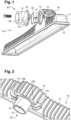
- Fig.1 presents a tank 10 for a heat exchanger 1, in particular for a motor vehicle.
- the tank 10 comprises a distribution body 11 responsible for distributing a coolant fluid across the heat exchanger 1 and a connector 20 that introduces the coolant fluid into the distribution body 11. Accordingly, in case of a reversed direction of the flow, the distribution body 11 and the connector 20 can play a role of the collecting devices.
- Both connector 20 and distribution body 11 can be made either of metal or synthetic material.
- the tank 10 distributes a coolant fluid by a first opening 12 disposed along the longitudinal direction of the distribution body 11.
- the first opening 12 has a substantially rectangular cross-section for receiving a header with tubes.
- the shape of the distribution body 11 presented in the Fig.1 is proven to ensure a homogenous distribution of coolant, yet other shapes of distribution body 11 that will provide similar or better performance are also allowed.
- the distribution body 11 comprises a plurality of transverse ribs deployed alternately in a direction perpendicular to the longitudinal direction of the distribution body 11. Ribs provide rigidity of distribution body 11 at high pressures and ensure reduced deformations of the tank 10.
- the distribution body 11 widens at the side of the opening to enable tight connection with the header (not shown).
- the tank 10 comprises a protrusion 16 bulging from the distribution body 11.
- the protrusion 16 is disposed between two far ends of the distribution body 11. This enables forming a second opening 13 either on the lateral side of the distribution body 11 or on the upper side thereof.
- the diameter of the second opening 13 disposed on the lateral side of the distribution body 11 is limited by the size of protrusion 16, whereas the diameter of the second opening 13 disposed on the upper side of the distribution body 11 is limited by the width of the distribution body 11, i.e. the diameter of the second opening 13 disposed on the upper side of the distribution body 11 is substantially equal to the length of the shorter side of the first opening 12.
- the protrusion 16 is of a greater dimensions than the second opening 13.
- the second opening 13 is disposed on the lateral side of the distribution body 11, as presented in the Figs 1, 2 , 5 and 6 .
- the second opening 13 is configured to receive a connector 20.
- the connector 20 is configured to assume at least two distinct angular positions with respect to the second opening 13.
- a second angular position allows connector 20 to be assembled to or disassembled from the tank 10, whereas a first angular position prevents the connector 20 from moving in the axis of the second opening 13 of the tank 10.
- the connector 20 in the first angular position is blocked from moving in the axis of the second opening 13, and is allowed to move in the axis of the second opening 13 in the second angular position.
- the tank assembly comprises guiding means 14, 15 and at the protruding portions 28, 29.
- the guiding means 14, 15 and the protruding portions 28, 29 are configured to cooperate with each other so as to engage the connector 20 with the tank 10 in a first angular position to prevent the connector 20 from moving in the axis of the second opening 13, and to disengage the connector 20 from the tank 10 in a second angular position in the plane delimited by the second opening 13.
- the guiding means 14, 15 comprise a guide 17a, 17b, 17c, 17d and the protruding portion 28, 29 comprise a protrusion 23a, 23b, 23c, 23d, wherein one of them is located on a tank 10 and a second one is located on the connector 20.
- the protrusion 23a, 23b, 23c, 23d is adapted to be engaged in the guide 17a, 17b, 17c, 17d, thereby restricting movement of the connector 20 in the axis of the second opening 13.
- Fig. 2 presents a tank 10 assembly comprising a distribution body 11 and the connector 20.
- the assembly is carried out by introducing the connector 20 to the second opening 13 and rotating it from second angular position to the first angular position, so that the connector is immobilized with respect to the tank 10.
- Immobilizing the connector 20 is carried out by the guiding means 14, 15 which are deployed in the vicinity of the second opening 13.
- the tank 10 comprises two guiding means 14, 15 deployed on the opposite sides of the second opening 13.
- the guiding means come into contact with the connector 20 after rotating it in the plane delimited by the second opening 13, so that the guiding means 14, 15 prevent the connector from moving outwardly from the distribution body 11.
- the embodiments comprising only one or more than two guiding means 14, 15 are also executable.
- the guiding means 14, 15 and the protruding portions 28, 29 shall also be distributed evenly at the circumference of the second opening 13.
- the guiding means 14, 15 comprise at least one guide 17a, 17b, 17c, 17d and the protruding portions 28, 29 comprise at least one protrusion 23a, 23b, 23c, 23d.
- the guides 17a, 17b, 17c, 17d are deployed on the tank 10 and the protrusions 23a, 23b, 23c, 23d are deployed on the connector 20.
- the guides 17a, 17b, 17c, 17d being deployed on the connector 20 and the protrusions 23a, 23b, 23c, 23d being deployed on the tank 10 are also envisaged.
- the guides 17a and 17b presented in the Fig. 2 protrude from the tank 10.
- guides 17a and 17b presented in the Fig. 2 protrude from the tank 10.
- guides are hereby presented.
- the friction guide 17a prevents the connector 20 from moving in an outward direction with respect to the tank 10 and it prevents rotation of the connector 20 in one direction after assembling it with the tank 10.
- the inner wall of the friction is sloping towards the outer wall of the tank 10, so that the distance between the adjacent walls of the friction is steadily reduced and consequently the friction between the connector 20 and the tank 10 inhibits movement of the connector 20 with respect to the tank 10.
- the outer wall of the friction guide 17a comprises ribs configured to prevent outward movement of the friction guide 17a with respect to the distribution body 11.
- a snap-fit guide 17b located opposite the friction guide 17a, as shown in Fig. 2 , prevents the connector 20 from moving in an outward direction in reference to the tank 10 and it prevents rotation of the connector 20 in two directions after assembling it with the tank 10.
- the snap-fit guide 17b may be L-shaped.
- the snap-fit guide 17b is configured as the hitching point for the connector 20.
- the outer wall of the snap-fit guide 17b comprises ribs configured to prevent outward movement of the snap-fit guiding means 17b with respect to the distribution body 11.
- the bolt-in guide 17c shares the functionality of the snap-fit guide 17b, i.e. it prevents the connector 20 from moving in an outward direction in reference to the tank 10 and it prevents rotation of the connector 20 in two directions after assembling it with the tank 10.
- the bolt-in guide 17c is in a form of the blind opening, which is configured to receive the threaded bolt, as shown in Fig. 1 and 5 . Moreover, it allows adjusting the tightness of the connection between the connector 20 and the tank 10.
- the bolt-in guide 17c cooperates with the bolt in order to immobilize the connector 20.
- the arched guide 17d presented in the Fig.6 is providing enough tightness to keep the connector 20 properly assembled with the tank 10.
- the arched guide 17d is in a form of a rounded portion that extends along the outer perimeter of the second opening 13.
- the arched guide 17d comprises a blocking-locking portion on one end to minimize the risk of disassembling the connector 20 from the tank 10.
- the invention includes different combinations of guiding means, i.e. the guiding means 14, 15 may be of different kind and/or different number.
- the distribution body 11 may comprise one snap-fit guide 17b and two friction guides 17a.
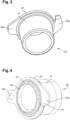
- the connector 20 comprises the connector body 21 and the collar 22 that comprises at least one protruding portion 28, 29 and a guiding means 26.
- the collar 22 is optional and an embodiment, wherein at least one protruding portion deployed directly on the connector body 21 is also feasible.
- the connector 20 comprises an essentially tubular connector body 21 extending in a longitudinal direction.
- the connector 20 may be beveled on both ends to facilitate assembling to other elements of the system.
- the inner diameter of the connector 20 remains constant, while its outer diameter may vary while comparing different cross-sections.
- the opening with a smaller cross-section is configured to receive the hose and the opening with a larger cross-section forms a collar 22 of the connector 20.
- the collar 22 is a portion of a circular shape protruding from the collector body 21 that is in a physical contact with the distribution body 11 when assembled. It plays multiple roles - for example, it makes the whole connector 20 more resistant to diagonal forces, provides even force distribution on the surface of the tank 10, prevents the hose from being introduced too far over the connector 20 and aligns the connector 20 for proper sealing.
- the collar 22 comprises at least one protrusion 23a, 23b, 23c, 23d.
- the protrusions 23a, 23b, 23c, 23d are configured to ensure firm connection between the tank 10 and the connector 20.
- the protrusion 23a, 23b, 23c, 23d cooperate with the guides 17a, 17b, 17c, 17d of the tank 10.
- a winglet protrusion 23a protruding from the collar 22 may have the shape of a cut rectangle with rounded corners, as presented in the Figs 3 and 4 .
- the winglet protrusion 23a is coupled with the friction guiding means 17a.
- the shape of the winglet protrusion 23a enables precise alignment before coupling it with the guiding means.
- the winglet protrusion 23a comprises also an outer wall sloping towards the shorter edge of the winglet protrusion 23a. The sloping wall causes the connector 20 to be tightened to the tank 10. Further rotation of the connector 20 is blocked by the shorter wall of the winglet potion 23a leaning against the inner wall of the friction guiding means 17a.
- a snap-fit protrusion 23b is presented in the Figs 2 and 3 comprises a protrusion that is configured to be inserted into the snap-fit guide 17b.
- the connector 20 is assembled with the tank 10 by the means of the snap-fit protrusion 23b comprising a spearhead tip configured to slide through the opening of the snap-fit guide 17b and anchor to it.
- a bolt-in opening protrusion 23c is configured to receive the bolt that tightens the connector 20 to the tank 10.
- the bolt-in opening protrusion 23c is preferably of a circular shape, yet a semicircular or D-shaped opening is also possible.
- D-shape is defined by cutting out a part of the material from circular opening visible in the Fig.4 along the plane defined essentially by the diameter thereof. D-shaped opening will immobilize the connector 20 in a transverse and outward direction and prevent its rotation as good as the opening of a fully circular shape.
- an arched protrusion 23d protrudes from the collar 22.
- the protrusion extends along the outer perimeter of the collar 21 so as to be coupled with the arched guide 17d.
- the arched protrusion 23d occupies from 30% to 50% of the perimeter of the collar 22. In the basic embodiment of an invention, the arched protrusion occupies about 40% of the outer perimeter of the collar 22.
- the invention includes different combinations of protruding portions 28, 29, i.e. the protruding portions 28, 29 may be of different kind and/or different number, for example, the connector 20 may comprise one snap-fit protrusion 23b and two winglet protrusions 23a. Preferably, all of the protruding portions 28, 29 should be equally spaced.
- the connector 20 must be tightly connected to the tank 10 in order to provide a sealing that will sustain pressure and temperature variations.
- the tight connection may be carried out by the guiding means 26 that protrude from the connector body 11.
- the guiding means 26 may have an inner diameter equal to the inner diameter of the connector body 11 and the outer diameter of the guiding means 26 may be slightly smaller than the diameter of the second opening 13. The difference in dimensions is selected so as to unable play between the connector 20 in reference to the tank 10, but enable smooth rotation of these two elements.
- the connector 20 comprises a sealing region 27 located in the vicinity of the outer perimeter of guiding means 26, on the bottom of the connector body 21.
- the sealing region 27 is essentially a groove in the connector body 21 configured to receive a sealing means 40 (e.g. gasket).
- the sealing region 27 comprises at least one sealing guide 41.
- the sealing guide 41 comprises two protrusions deployed on the inner perimeter of the sealing region 27 and one protrusion on the outer perimeter of the sealing region 27. The sealing guide 41 preserves pinching and rotating the sealing means 40 in reference to the connector body 21.
Landscapes
- Engineering & Computer Science (AREA)
- Physics & Mathematics (AREA)
- Thermal Sciences (AREA)
- Mechanical Engineering (AREA)
- General Engineering & Computer Science (AREA)
- Cooling, Air Intake And Gas Exhaust, And Fuel Tank Arrangements In Propulsion Units (AREA)
Claims (11)
- Ensemble réservoir comprenant un réservoir (10) pour un échangeur de chaleur, en particulier pour un véhicule à moteur, comprenant :un corps de distribution (11) destiné à distribuer un fluide réfrigérant dans l'échangeur de chaleur ;une première ouverture (12) disposée le long de la direction longitudinale du corps de distribution (11), la première ouverture (12) ayant une forme sensiblement rectangulaire destinée à recevoir un collecteur muni de tubes ;une seconde ouverture (13) disposée sur la surface du corps de distribution (11), la seconde ouverture (13) ayant une forme circulaire ;au moins un moyen de guidage (14, 15) disposé au voisinage de la seconde ouverture (13), etun raccord (20) comprenant au moins une partie en saillie (28, 29) coopérant avec le moyen de guidage (14, 15), le raccord (20) étant conçu pour être assemblé avec le réservoir (10),dans lequel le moyen de guidage (14, 15) et la partie en saillie (28, 29) sont conçus pour mettre en prise le raccord (20) avec le réservoir (10) dans une première position angulaire pour empêcher le raccord (20) de se déplacer dans l'axe de la seconde ouverture (13), et pour dégager le raccord (20) du réservoir (10) dans une seconde position angulaire dans le plan défini par la seconde ouverture (13), dans lequel le moyen de guidage (14, 15) comprend un guide (17a, 17b, 17c, 17d) et la partie en saillie (28, 29) comprend une protubérance (23a, 23b, 23c, 23d), dans lequel l'un des deux est situé sur le réservoir (10) et l'autre est situé sur le raccord (20), dans lequel la protubérance (23a, 23b, 23c, 23d) est conçue pour venir en prise dans le guide (17a, 17b, 17c, 17d), limitant ainsi le déplacement du raccord (20) dans l'axe de la seconde ouverture (13), dans lequel le guide (17a, 17b, 17c, 17d) est conçu pour fixer le raccord (20) de façon détachable dans la première position angulaire,caractérisé en ce que la partie en saillie (28, 29) se présente sous la forme d'une ailette (23a), l'ailette (23a) étant de forme aplatie et comprenant une pente conçue pour interagir avec le guide (14, 15).
- Ensemble réservoir selon la revendication 1, dans lequel le réservoir (10) comprend une projection de réservoir (16) formant un renflement sur le corps de distribution (11), la projection de réservoir (16) étant disposée entre deux extrémités éloignées du corps de distribution (11) ; la projection de réservoir (16) étant conçue pour loger la seconde ouverture (13).
- Ensemble réservoir selon l'une quelconque des revendications précédentes, dans lequel la seconde ouverture (13) est disposée sur le côté latéral du corps de distribution (11) par rapport à la première ouverture (12) .
- Ensemble réservoir selon l'une quelconque des revendications précédentes, dans lequel la seconde ouverture (13) est disposée sur le côté opposé du corps de distribution (11) par rapport à la première ouverture (12) .
- Ensemble réservoir selon l'une quelconque des revendications précédentes, dans lequel le raccord (20) comprend un corps de raccord (21), le corps de raccord (21) étant de forme essentiellement tubulaire qui s'élargit sur l'extrémité adjacente au réservoir (10), formant ainsi un collier (22).
- Ensemble réservoir selon l'une quelconque des revendications précédentes, dans lequel la partie en saillie (28, 29) se présente sous la forme d'une protubérance à emboîtement (23b) comprenant une pointe avant conçue pour coulisser à travers le moyen de guidage (14, 15) et s'ancrer à celui-ci.
- Ensemble réservoir selon l'une quelconque des revendications précédentes, dans lequel le corps de raccord (21) comprend une région d'étanchéité (27) disposée au voisinage du périmètre externe du moyen de guidage (26) pour loger un moyen d'étanchéité (40).
- Ensemble réservoir selon la revendication 6, dans lequel la région d'étanchéité (27) comprend au moins un ensemble de guides d'étanchéité (41), le guide d'étanchéité (41) comprenant au moins deux protubérances sur le périmètre interne de la région d'étanchéité (27) et au moins une protubérance sur le périmètre externe de la région d'étanchéité (27), de sorte qu'un moyen d'étanchéité (40) est empêché de tourner à l'encontre du corps de raccord (21) après son insertion dans la région d'étanchéité (27).
- Ensemble réservoir selon l'une quelconque des revendications précédentes, dans lequel le moyen d'étanchéité (40) se présente sous la forme d'un joint d'étanchéité en caoutchouc.
- Ensemble réservoir selon l'une quelconque des revendications précédentes, dans lequel une pluralité de protubérances (23a, 23b, 23c, 23d) sont situées sur les côtés opposés du raccord (20).
- Échangeur de chaleur comprenant un ensemble réservoir selon toutes les revendications précédentes.
Priority Applications (2)
| Application Number | Priority Date | Filing Date | Title |
|---|---|---|---|
| EP19461546.4A EP3757501B1 (fr) | 2019-06-26 | 2019-06-26 | Ensemble de réservoir pour échangeur de chaleur |
| PCT/EP2020/067511 WO2020260287A1 (fr) | 2019-06-26 | 2020-06-23 | Ensemble réservoir pour échangeur de chaleur |
Applications Claiming Priority (1)
| Application Number | Priority Date | Filing Date | Title |
|---|---|---|---|
| EP19461546.4A EP3757501B1 (fr) | 2019-06-26 | 2019-06-26 | Ensemble de réservoir pour échangeur de chaleur |
Publications (2)
| Publication Number | Publication Date |
|---|---|
| EP3757501A1 EP3757501A1 (fr) | 2020-12-30 |
| EP3757501B1 true EP3757501B1 (fr) | 2023-03-15 |
Family
ID=67105965
Family Applications (1)
| Application Number | Title | Priority Date | Filing Date |
|---|---|---|---|
| EP19461546.4A Active EP3757501B1 (fr) | 2019-06-26 | 2019-06-26 | Ensemble de réservoir pour échangeur de chaleur |
Country Status (2)
| Country | Link |
|---|---|
| EP (1) | EP3757501B1 (fr) |
| WO (1) | WO2020260287A1 (fr) |
Family Cites Families (3)
| Publication number | Priority date | Publication date | Assignee | Title |
|---|---|---|---|---|
| DE4129397C1 (fr) * | 1991-09-04 | 1993-03-11 | Rasmussen Gmbh, 6457 Maintal, De | |
| DE60100862T3 (de) * | 2000-05-29 | 2011-03-17 | Valeo Thermique Moteur | Endkammer für einen gelöteten wärmetauscher |
| JP4689065B2 (ja) * | 2001-03-26 | 2011-05-25 | カルソニックカンセイ株式会社 | 管体の仮固定構造 |
-
2019
- 2019-06-26 EP EP19461546.4A patent/EP3757501B1/fr active Active
-
2020
- 2020-06-23 WO PCT/EP2020/067511 patent/WO2020260287A1/fr active Application Filing
Also Published As
| Publication number | Publication date |
|---|---|
| WO2020260287A1 (fr) | 2020-12-30 |
| EP3757501A1 (fr) | 2020-12-30 |
Similar Documents
| Publication | Publication Date | Title |
|---|---|---|
| TWI681139B (zh) | 用於接合管元件之聯結器 | |
| CN108779883B (zh) | 带有弹簧的联接器 | |
| EP0800631B1 (fr) | Connecteur rapide enclenchable | |
| EP2516916B1 (fr) | Connecteur à baïonnette mâle | |
| KR102044649B1 (ko) | 탭이 형성된 리테이너 및 관찰 구멍을 가지는 피팅 | |
| US11692653B2 (en) | Pre-assembled pipe coupling with an insertion boundary for axial receipt of pipe ends | |
| US5542716A (en) | Quick connector with snap-on retainer | |
| US20100052315A1 (en) | Quick connector coupling with lateral stabilization | |
| CN108291662B (zh) | 具有定中心支承突出部的阀联接件 | |
| WO2008106654A2 (fr) | Adaptateur à bride en deux pièces | |
| EP3757501B1 (fr) | Ensemble de réservoir pour échangeur de chaleur | |
| US5271460A (en) | Tube fastener | |
| EP2717009A2 (fr) | Échangeur de chaleur doté d'un élément de support | |
| BRPI1004419A2 (pt) | conjunto de acoplamento, unidade de condicionamento de ar, e, método para acoplar um componente tubular de uma unidade de condicionamento de ar para veiculo a uma parte de conexão | |
| US20140300061A1 (en) | Bullet Nose Grommet for Radiator Assembly | |
| EP1637791A2 (fr) | Raccord de fluide rapide avec un dispositif de retenue coulissant | |
| US20190339028A1 (en) | Fluid inlet-outlet manifold | |
| KR20180124660A (ko) | 파형관 연결장치 | |
| EP1653143A1 (fr) | Raccord rapide pour fluides avec un adaptateur | |
| US9488290B2 (en) | Disc check valve system and method | |
| JP3798357B2 (ja) | 継手構造 | |
| JP2018059560A (ja) | 配管接続構造 | |
| EP3789720A1 (fr) | Échangeur de chaleur | |
| DE69620917T2 (de) | Schnellkupplung | |
| RU2000522C1 (ru) | Устройство дл соединени секций воздуховода круглого сечени |
Legal Events
| Date | Code | Title | Description |
|---|---|---|---|
| PUAI | Public reference made under article 153(3) epc to a published international application that has entered the european phase |
Free format text: ORIGINAL CODE: 0009012 |
|
| STAA | Information on the status of an ep patent application or granted ep patent |
Free format text: STATUS: THE APPLICATION HAS BEEN PUBLISHED |
|
| AK | Designated contracting states |
Kind code of ref document: A1 Designated state(s): AL AT BE BG CH CY CZ DE DK EE ES FI FR GB GR HR HU IE IS IT LI LT LU LV MC MK MT NL NO PL PT RO RS SE SI SK SM TR |
|
| AX | Request for extension of the european patent |
Extension state: BA ME |
|
| STAA | Information on the status of an ep patent application or granted ep patent |
Free format text: STATUS: REQUEST FOR EXAMINATION WAS MADE |
|
| 17P | Request for examination filed |
Effective date: 20210623 |
|
| RBV | Designated contracting states (corrected) |
Designated state(s): AL AT BE BG CH CY CZ DE DK EE ES FI FR GB GR HR HU IE IS IT LI LT LU LV MC MK MT NL NO PL PT RO RS SE SI SK SM TR |
|
| GRAP | Despatch of communication of intention to grant a patent |
Free format text: ORIGINAL CODE: EPIDOSNIGR1 |
|
| STAA | Information on the status of an ep patent application or granted ep patent |
Free format text: STATUS: GRANT OF PATENT IS INTENDED |
|
| INTG | Intention to grant announced |
Effective date: 20221123 |
|
| GRAS | Grant fee paid |
Free format text: ORIGINAL CODE: EPIDOSNIGR3 |
|
| GRAA | (expected) grant |
Free format text: ORIGINAL CODE: 0009210 |
|
| STAA | Information on the status of an ep patent application or granted ep patent |
Free format text: STATUS: THE PATENT HAS BEEN GRANTED |
|
| AK | Designated contracting states |
Kind code of ref document: B1 Designated state(s): AL AT BE BG CH CY CZ DE DK EE ES FI FR GB GR HR HU IE IS IT LI LT LU LV MC MK MT NL NO PL PT RO RS SE SI SK SM TR |
|
| REG | Reference to a national code |
Ref country code: CH Ref legal event code: EP Ref country code: GB Ref legal event code: FG4D |
|
| REG | Reference to a national code |
Ref country code: DE Ref legal event code: R096 Ref document number: 602019026386 Country of ref document: DE |
|
| REG | Reference to a national code |
Ref country code: IE Ref legal event code: FG4D |
|
| REG | Reference to a national code |
Ref country code: AT Ref legal event code: REF Ref document number: 1554227 Country of ref document: AT Kind code of ref document: T Effective date: 20230415 |
|
| REG | Reference to a national code |
Ref country code: LT Ref legal event code: MG9D |
|
| P01 | Opt-out of the competence of the unified patent court (upc) registered |
Effective date: 20230528 |
|
| REG | Reference to a national code |
Ref country code: NL Ref legal event code: MP Effective date: 20230315 |
|
| PG25 | Lapsed in a contracting state [announced via postgrant information from national office to epo] |
Ref country code: RS Free format text: LAPSE BECAUSE OF FAILURE TO SUBMIT A TRANSLATION OF THE DESCRIPTION OR TO PAY THE FEE WITHIN THE PRESCRIBED TIME-LIMIT Effective date: 20230315 Ref country code: NO Free format text: LAPSE BECAUSE OF FAILURE TO SUBMIT A TRANSLATION OF THE DESCRIPTION OR TO PAY THE FEE WITHIN THE PRESCRIBED TIME-LIMIT Effective date: 20230615 Ref country code: LV Free format text: LAPSE BECAUSE OF FAILURE TO SUBMIT A TRANSLATION OF THE DESCRIPTION OR TO PAY THE FEE WITHIN THE PRESCRIBED TIME-LIMIT Effective date: 20230315 Ref country code: LT Free format text: LAPSE BECAUSE OF FAILURE TO SUBMIT A TRANSLATION OF THE DESCRIPTION OR TO PAY THE FEE WITHIN THE PRESCRIBED TIME-LIMIT Effective date: 20230315 Ref country code: HR Free format text: LAPSE BECAUSE OF FAILURE TO SUBMIT A TRANSLATION OF THE DESCRIPTION OR TO PAY THE FEE WITHIN THE PRESCRIBED TIME-LIMIT Effective date: 20230315 |
|
| REG | Reference to a national code |
Ref country code: AT Ref legal event code: MK05 Ref document number: 1554227 Country of ref document: AT Kind code of ref document: T Effective date: 20230315 |
|
| PG25 | Lapsed in a contracting state [announced via postgrant information from national office to epo] |
Ref country code: SE Free format text: LAPSE BECAUSE OF FAILURE TO SUBMIT A TRANSLATION OF THE DESCRIPTION OR TO PAY THE FEE WITHIN THE PRESCRIBED TIME-LIMIT Effective date: 20230315 Ref country code: NL Free format text: LAPSE BECAUSE OF FAILURE TO SUBMIT A TRANSLATION OF THE DESCRIPTION OR TO PAY THE FEE WITHIN THE PRESCRIBED TIME-LIMIT Effective date: 20230315 Ref country code: GR Free format text: LAPSE BECAUSE OF FAILURE TO SUBMIT A TRANSLATION OF THE DESCRIPTION OR TO PAY THE FEE WITHIN THE PRESCRIBED TIME-LIMIT Effective date: 20230616 Ref country code: FI Free format text: LAPSE BECAUSE OF FAILURE TO SUBMIT A TRANSLATION OF THE DESCRIPTION OR TO PAY THE FEE WITHIN THE PRESCRIBED TIME-LIMIT Effective date: 20230315 |
|
| PG25 | Lapsed in a contracting state [announced via postgrant information from national office to epo] |
Ref country code: SM Free format text: LAPSE BECAUSE OF FAILURE TO SUBMIT A TRANSLATION OF THE DESCRIPTION OR TO PAY THE FEE WITHIN THE PRESCRIBED TIME-LIMIT Effective date: 20230315 Ref country code: RO Free format text: LAPSE BECAUSE OF FAILURE TO SUBMIT A TRANSLATION OF THE DESCRIPTION OR TO PAY THE FEE WITHIN THE PRESCRIBED TIME-LIMIT Effective date: 20230315 Ref country code: PT Free format text: LAPSE BECAUSE OF FAILURE TO SUBMIT A TRANSLATION OF THE DESCRIPTION OR TO PAY THE FEE WITHIN THE PRESCRIBED TIME-LIMIT Effective date: 20230717 Ref country code: ES Free format text: LAPSE BECAUSE OF FAILURE TO SUBMIT A TRANSLATION OF THE DESCRIPTION OR TO PAY THE FEE WITHIN THE PRESCRIBED TIME-LIMIT Effective date: 20230315 Ref country code: EE Free format text: LAPSE BECAUSE OF FAILURE TO SUBMIT A TRANSLATION OF THE DESCRIPTION OR TO PAY THE FEE WITHIN THE PRESCRIBED TIME-LIMIT Effective date: 20230315 Ref country code: CZ Free format text: LAPSE BECAUSE OF FAILURE TO SUBMIT A TRANSLATION OF THE DESCRIPTION OR TO PAY THE FEE WITHIN THE PRESCRIBED TIME-LIMIT Effective date: 20230315 Ref country code: AT Free format text: LAPSE BECAUSE OF FAILURE TO SUBMIT A TRANSLATION OF THE DESCRIPTION OR TO PAY THE FEE WITHIN THE PRESCRIBED TIME-LIMIT Effective date: 20230315 |
|
| PG25 | Lapsed in a contracting state [announced via postgrant information from national office to epo] |
Ref country code: SK Free format text: LAPSE BECAUSE OF FAILURE TO SUBMIT A TRANSLATION OF THE DESCRIPTION OR TO PAY THE FEE WITHIN THE PRESCRIBED TIME-LIMIT Effective date: 20230315 Ref country code: PL Free format text: LAPSE BECAUSE OF FAILURE TO SUBMIT A TRANSLATION OF THE DESCRIPTION OR TO PAY THE FEE WITHIN THE PRESCRIBED TIME-LIMIT Effective date: 20230315 Ref country code: IS Free format text: LAPSE BECAUSE OF FAILURE TO SUBMIT A TRANSLATION OF THE DESCRIPTION OR TO PAY THE FEE WITHIN THE PRESCRIBED TIME-LIMIT Effective date: 20230715 |
|
| REG | Reference to a national code |
Ref country code: DE Ref legal event code: R097 Ref document number: 602019026386 Country of ref document: DE |
|
| PG25 | Lapsed in a contracting state [announced via postgrant information from national office to epo] |
Ref country code: MC Free format text: LAPSE BECAUSE OF FAILURE TO SUBMIT A TRANSLATION OF THE DESCRIPTION OR TO PAY THE FEE WITHIN THE PRESCRIBED TIME-LIMIT Effective date: 20230315 |
|
| PLBE | No opposition filed within time limit |
Free format text: ORIGINAL CODE: 0009261 |
|
| STAA | Information on the status of an ep patent application or granted ep patent |
Free format text: STATUS: NO OPPOSITION FILED WITHIN TIME LIMIT |
|
| PG25 | Lapsed in a contracting state [announced via postgrant information from national office to epo] |
Ref country code: SI Free format text: LAPSE BECAUSE OF FAILURE TO SUBMIT A TRANSLATION OF THE DESCRIPTION OR TO PAY THE FEE WITHIN THE PRESCRIBED TIME-LIMIT Effective date: 20230315 Ref country code: MC Free format text: LAPSE BECAUSE OF FAILURE TO SUBMIT A TRANSLATION OF THE DESCRIPTION OR TO PAY THE FEE WITHIN THE PRESCRIBED TIME-LIMIT Effective date: 20230315 Ref country code: DK Free format text: LAPSE BECAUSE OF FAILURE TO SUBMIT A TRANSLATION OF THE DESCRIPTION OR TO PAY THE FEE WITHIN THE PRESCRIBED TIME-LIMIT Effective date: 20230315 |
|
| REG | Reference to a national code |
Ref country code: CH Ref legal event code: PL |
|
| 26N | No opposition filed |
Effective date: 20231218 |
|
| REG | Reference to a national code |
Ref country code: BE Ref legal event code: MM Effective date: 20230630 |
|
| GBPC | Gb: european patent ceased through non-payment of renewal fee |
Effective date: 20230626 |
|
| PG25 | Lapsed in a contracting state [announced via postgrant information from national office to epo] |
Ref country code: LU Free format text: LAPSE BECAUSE OF NON-PAYMENT OF DUE FEES Effective date: 20230626 |
|
| REG | Reference to a national code |
Ref country code: IE Ref legal event code: MM4A |
|
| PG25 | Lapsed in a contracting state [announced via postgrant information from national office to epo] |
Ref country code: LU Free format text: LAPSE BECAUSE OF NON-PAYMENT OF DUE FEES Effective date: 20230626 |
|
| PG25 | Lapsed in a contracting state [announced via postgrant information from national office to epo] |
Ref country code: IE Free format text: LAPSE BECAUSE OF NON-PAYMENT OF DUE FEES Effective date: 20230626 |
|
| PG25 | Lapsed in a contracting state [announced via postgrant information from national office to epo] |
Ref country code: IE Free format text: LAPSE BECAUSE OF NON-PAYMENT OF DUE FEES Effective date: 20230626 Ref country code: CH Free format text: LAPSE BECAUSE OF NON-PAYMENT OF DUE FEES Effective date: 20230630 Ref country code: GB Free format text: LAPSE BECAUSE OF NON-PAYMENT OF DUE FEES Effective date: 20230626 |
|
| PG25 | Lapsed in a contracting state [announced via postgrant information from national office to epo] |
Ref country code: IT Free format text: LAPSE BECAUSE OF FAILURE TO SUBMIT A TRANSLATION OF THE DESCRIPTION OR TO PAY THE FEE WITHIN THE PRESCRIBED TIME-LIMIT Effective date: 20230315 Ref country code: BE Free format text: LAPSE BECAUSE OF NON-PAYMENT OF DUE FEES Effective date: 20230630 |
|
| PGFP | Annual fee paid to national office [announced via postgrant information from national office to epo] |
Ref country code: DE Payment date: 20240613 Year of fee payment: 6 |
|
| PGFP | Annual fee paid to national office [announced via postgrant information from national office to epo] |
Ref country code: FR Payment date: 20240625 Year of fee payment: 6 |