EP3757499B1 - Röhrenwärmetauscher - Google Patents
Röhrenwärmetauscher Download PDFInfo
- Publication number
- EP3757499B1 EP3757499B1 EP20174592.4A EP20174592A EP3757499B1 EP 3757499 B1 EP3757499 B1 EP 3757499B1 EP 20174592 A EP20174592 A EP 20174592A EP 3757499 B1 EP3757499 B1 EP 3757499B1
- Authority
- EP
- European Patent Office
- Prior art keywords
- flange plate
- heat exchanger
- tubular heat
- flange
- central axis
- Prior art date
- Legal status (The legal status is an assumption and is not a legal conclusion. Google has not performed a legal analysis and makes no representation as to the accuracy of the status listed.)
- Active
Links
Images




Classifications
-
- F—MECHANICAL ENGINEERING; LIGHTING; HEATING; WEAPONS; BLASTING
- F28—HEAT EXCHANGE IN GENERAL
- F28D—HEAT-EXCHANGE APPARATUS, NOT PROVIDED FOR IN ANOTHER SUBCLASS, IN WHICH THE HEAT-EXCHANGE MEDIA DO NOT COME INTO DIRECT CONTACT
- F28D7/00—Heat-exchange apparatus having stationary tubular conduit assemblies for both heat-exchange media, the media being in contact with different sides of a conduit wall
- F28D7/16—Heat-exchange apparatus having stationary tubular conduit assemblies for both heat-exchange media, the media being in contact with different sides of a conduit wall the conduits being arranged in parallel spaced relation
-
- B—PERFORMING OPERATIONS; TRANSPORTING
- B33—ADDITIVE MANUFACTURING TECHNOLOGY
- B33Y—ADDITIVE MANUFACTURING, i.e. MANUFACTURING OF THREE-DIMENSIONAL [3D] OBJECTS BY ADDITIVE DEPOSITION, ADDITIVE AGGLOMERATION OR ADDITIVE LAYERING, e.g. BY 3D PRINTING, STEREOLITHOGRAPHY OR SELECTIVE LASER SINTERING
- B33Y80/00—Products made by additive manufacturing
-
- F—MECHANICAL ENGINEERING; LIGHTING; HEATING; WEAPONS; BLASTING
- F28—HEAT EXCHANGE IN GENERAL
- F28D—HEAT-EXCHANGE APPARATUS, NOT PROVIDED FOR IN ANOTHER SUBCLASS, IN WHICH THE HEAT-EXCHANGE MEDIA DO NOT COME INTO DIRECT CONTACT
- F28D7/00—Heat-exchange apparatus having stationary tubular conduit assemblies for both heat-exchange media, the media being in contact with different sides of a conduit wall
- F28D7/10—Heat-exchange apparatus having stationary tubular conduit assemblies for both heat-exchange media, the media being in contact with different sides of a conduit wall the conduits being arranged one within the other, e.g. concentrically
-
- F—MECHANICAL ENGINEERING; LIGHTING; HEATING; WEAPONS; BLASTING
- F28—HEAT EXCHANGE IN GENERAL
- F28F—DETAILS OF HEAT-EXCHANGE AND HEAT-TRANSFER APPARATUS, OF GENERAL APPLICATION
- F28F19/00—Preventing the formation of deposits or corrosion, e.g. by using filters or scrapers
-
- F—MECHANICAL ENGINEERING; LIGHTING; HEATING; WEAPONS; BLASTING
- F28—HEAT EXCHANGE IN GENERAL
- F28F—DETAILS OF HEAT-EXCHANGE AND HEAT-TRANSFER APPARATUS, OF GENERAL APPLICATION
- F28F9/00—Casings; Header boxes; Auxiliary supports for elements; Auxiliary members within casings
- F28F9/02—Header boxes; End plates
- F28F9/0219—Arrangements for sealing end plates into casing or header box; Header box sub-elements
-
- F—MECHANICAL ENGINEERING; LIGHTING; HEATING; WEAPONS; BLASTING
- F28—HEAT EXCHANGE IN GENERAL
- F28F—DETAILS OF HEAT-EXCHANGE AND HEAT-TRANSFER APPARATUS, OF GENERAL APPLICATION
- F28F9/00—Casings; Header boxes; Auxiliary supports for elements; Auxiliary members within casings
- F28F9/02—Header boxes; End plates
- F28F9/026—Header boxes; End plates with static flow control means, e.g. with means for uniformly distributing heat exchange media into conduits
-
- F—MECHANICAL ENGINEERING; LIGHTING; HEATING; WEAPONS; BLASTING
- F28—HEAT EXCHANGE IN GENERAL
- F28F—DETAILS OF HEAT-EXCHANGE AND HEAT-TRANSFER APPARATUS, OF GENERAL APPLICATION
- F28F9/00—Casings; Header boxes; Auxiliary supports for elements; Auxiliary members within casings
- F28F9/02—Header boxes; End plates
- F28F9/026—Header boxes; End plates with static flow control means, e.g. with means for uniformly distributing heat exchange media into conduits
- F28F9/0263—Header boxes; End plates with static flow control means, e.g. with means for uniformly distributing heat exchange media into conduits by varying the geometry or cross-section of header box
-
- F—MECHANICAL ENGINEERING; LIGHTING; HEATING; WEAPONS; BLASTING
- F28—HEAT EXCHANGE IN GENERAL
- F28F—DETAILS OF HEAT-EXCHANGE AND HEAT-TRANSFER APPARATUS, OF GENERAL APPLICATION
- F28F9/00—Casings; Header boxes; Auxiliary supports for elements; Auxiliary members within casings
- F28F9/02—Header boxes; End plates
- F28F9/04—Arrangements for sealing elements into header boxes or end plates
- F28F9/06—Arrangements for sealing elements into header boxes or end plates by dismountable joints
- F28F9/12—Arrangements for sealing elements into header boxes or end plates by dismountable joints by flange-type connections
-
- F—MECHANICAL ENGINEERING; LIGHTING; HEATING; WEAPONS; BLASTING
- F28—HEAT EXCHANGE IN GENERAL
- F28F—DETAILS OF HEAT-EXCHANGE AND HEAT-TRANSFER APPARATUS, OF GENERAL APPLICATION
- F28F9/00—Casings; Header boxes; Auxiliary supports for elements; Auxiliary members within casings
- F28F9/02—Header boxes; End plates
- F28F9/04—Arrangements for sealing elements into header boxes or end plates
- F28F9/16—Arrangements for sealing elements into header boxes or end plates by permanent joints, e.g. by rolling
- F28F9/18—Arrangements for sealing elements into header boxes or end plates by permanent joints, e.g. by rolling by welding
-
- F—MECHANICAL ENGINEERING; LIGHTING; HEATING; WEAPONS; BLASTING
- F28—HEAT EXCHANGE IN GENERAL
- F28F—DETAILS OF HEAT-EXCHANGE AND HEAT-TRANSFER APPARATUS, OF GENERAL APPLICATION
- F28F9/00—Casings; Header boxes; Auxiliary supports for elements; Auxiliary members within casings
- F28F9/26—Arrangements for connecting different sections of heat-exchange elements, e.g. of radiators
-
- F—MECHANICAL ENGINEERING; LIGHTING; HEATING; WEAPONS; BLASTING
- F28—HEAT EXCHANGE IN GENERAL
- F28F—DETAILS OF HEAT-EXCHANGE AND HEAT-TRANSFER APPARATUS, OF GENERAL APPLICATION
- F28F9/00—Casings; Header boxes; Auxiliary supports for elements; Auxiliary members within casings
- F28F9/02—Header boxes; End plates
- F28F2009/0285—Other particular headers or end plates
-
- F—MECHANICAL ENGINEERING; LIGHTING; HEATING; WEAPONS; BLASTING
- F28—HEAT EXCHANGE IN GENERAL
- F28F—DETAILS OF HEAT-EXCHANGE AND HEAT-TRANSFER APPARATUS, OF GENERAL APPLICATION
- F28F9/00—Casings; Header boxes; Auxiliary supports for elements; Auxiliary members within casings
- F28F9/02—Header boxes; End plates
- F28F2009/0285—Other particular headers or end plates
- F28F2009/029—Other particular headers or end plates with increasing or decreasing cross-section, e.g. having conical shape
Definitions
- the invention relates to a tubular heat exchanger according to the preamble of claim 1.
- a tubular heat exchanger is from U.S. 4,207,944 known.
- Shell and tube heat exchangers generally have a housing in which a plurality of tubes that run essentially parallel are arranged. During operation, a first medium flows inside the tubes and a second medium, also called secondary medium, flows around the tubes inside the housing.
- the area in which the first medium flows is referred to as the primary side of the tube heat exchanger and the area of the heat exchanger interior in which the second medium flows is referred to as the secondary side of the tube heat exchanger.
- At least one end of the housing is closed off by a flange plate, which also represents a connection piece to other process areas.
- the flange plate is designed in such a way that it has passages through which the first medium can flow out of the tubular heat exchanger.
- the tubes can be attached to these passages.
- the inner diameter of the passages is chosen to correspond to the inner diameter of the tubes.
- the tubes can be inserted into the passages.
- the inner diameter of the passages is preferably selected in such a way that the outer diameter of the tubes is only slightly smaller than the inner diameter of the passages.
- the surface of the inside of the flange plate is flat and essentially perpendicular to the tubes.
- the surface of the inside of the flange plate is flat and essentially perpendicular to the tubes. Said side walls typically run parallel to the tubes.
- tubular heat exchangers have one or more flange plates, for example as a cover and/or base piece, which on the side facing the interior of the heat exchanger (secondary side) has an essentially flat surface perpendicular to the tubes and thus typically also to the housing (also called jacket tube ), exhibit.
- Both the known tubular heat exchangers according to the invention and those described below can be designed, for example, so that the secondary medium flows through an inlet into the interior of the heat exchanger, where it flows along the tubes to an outlet through which it leaves the interior of the heat exchanger, flowing around the tubes .
- the flow direction in the inlet and/or outlet ie the inflow direction or outflow direction, can in particular be perpendicular to the longitudinal direction of the tubes. That is, the longitudinal direction of tubes or nozzles forming the inlet and outlet respectively can be perpendicular to the longitudinal direction of the tubes.
- dead zones can arise, particularly in an area diametrically opposed to the entry or exit on the secondary side.
- the area “diametrically to the inlet or outlet on the secondary side” means that which lies opposite the inlet or outlet of the secondary medium. This can in particular include the area of the side wall of the heat exchanger interior opposite the inlet or outlet. There can also be a less well-flowed area in the area of the necking of the inlet or outlet facing the flange plate.
- Another problem is that the second medium lingers longer in the areas of the dead zones than in others. A broader residence time spectrum is thus obtained. This leads to an uneven heat exchange.
- the flange plate has an uneven, ie three-dimensional flange surface on the secondary side, for example a single or multiple curved surface.
- Such a configuration makes it possible to specifically influence the flow in the area around the flange surface, in particular to accelerate it in selected areas.
- the flange plate thus has a flange surface with elevations or shaped surfaces.
- the deepest points of the sections of the flange surface lying between the sockets can at least partially lie on different planes perpendicular to the direction in which the receiving sockets or the passages extend. This means that, for example, in a cross section with a section plane parallel to said direction of extension, which runs through a first, second and third receiving socket (or passage), the minimum height of the relief between a first and a second receiving socket (or passage) is one has a different value than the minimum height of the relief between the second and the third receiving socket or passage.
- the surface of the flange plate pointing towards the interior of the heat exchanger can in particular be designed in such a way that more than 30%, in particular more than 40%, in particular more than 50% of the surface of the flange plate facing towards the interior of the heat exchanger has a curvature other than 0.
- the surface of the flange plate pointing towards the inside of the heat exchanger can be designed in particular in such a way that more than 30%, in particular more than 40%, in particular more than 50% of the surface of the flange plate pointing towards the inside of the heat exchanger has a slope other than 0 with respect to a connection piece or Have passages perpendicular plane.
- the flange surface can in particular be contoured in such a way that the dead zones described above, in particular in the area opposite the inlet and outlet opening of the secondary space and directly in the flow shadow at the inlet and outlet, be avoided.
- the contours can be designed in such a way that right angles are avoided.
- the flange plate is thus designed in such a way that the flow of a medium (second medium) is improved, in particular the flow speed is increased in the dead zones.
- a medium second medium
- the flow speed is increased in the dead zones.
- the flange plate is connected to the tubes in such a way that a medium (first medium) can flow into or out of the tubes through the passages.
- the flange plate can comprise a plurality of essentially hollow-cylindrical receiving sockets, each for receiving one of the tubes of the tubular heat exchanger on the side facing the interior of the heat exchanger, with an outside of the receiving sockets opening into the flange surface.
- the flange surface is the contact surface of the outer surface of the receiving socket.
- the receiving sockets are also referred to as approaches for the weld seam.
- the receiving sockets can also be viewed as extensions of the passages.
- the distance between the receiving sockets and the primary-side surface of the flange plate is constant for all receiving sockets.
- the inside diameter of the receiving socket can be selected in particular in such a way that the tubes can be received in the receiving socket, the outside diameter of the tubes being only slightly smaller than the inside diameter of the receiving socket.
- the tubes can also be inserted through the flange plate. In other words, the tubes can extend through the entire thickness of the flange plate.
- a relief of the flange surface in cross section, in particular through the central axis of the flange plate, is curved once or multiple times. That is, the curvature may be non-zero in one or more regions of the relief. However, the relief can also have areas without curvature.
- the central axis is an axis that runs parallel to the passages and through the geometric center of gravity of the base area, for example through the center point of the circle in the case of a circular base area.
- an area with a certain sign of curvature i.e. a convex or concave area
- a convex or concave area is to be understood as a continuous section of the relief in which the sign of curvature is the same, i.e. the continuous section of the relief between two adjacent turning points.
- two adjacent sections that connect to a passageway or socket and have the same sign of curvature are also considered to be part of the same area.
- an area can include adjacent sections with the same sign of curvature, in particular also adjacent sections with the same sign of curvature that are separated by a receiving socket or a passage.
- a region can extend across a passage or receiving socket, which is the case when a section with the same sign of curvature adjoins the receiving socket or the passage on both sides of the receiving socket or the passage.
- the slope in one, several or all areas of the relief can be non-zero.
- cross-section is meant here a cross-section through a surface parallel to the passages in the gland plate or tubes.
- the relief describes the height of the flange surface in the respective cross-section. It can also be called a profile.
- the height can be defined in relation to any reference surface that is perpendicular to the cross-sectional surface and is arranged towards the outside of the heat exchanger in such a way that it does not intersect the flange surface. If the side of the flange plate opposite the flange surface, i.e. the side facing the outside of the heat exchanger, is flat, this can be used as a reference surface.
- curvatures and gradients of the relief can in principle apply to reliefs of any selected cross section.
- the statements can apply, for example, to one, several, or all cross sections through the central axis. In the latter case, a rotational symmetry then results.
- the statements can, for example, also apply to all parallel cross sections along a specific direction.
- the relief has at least one concave and at least one convex area. This means that the relief can have at least one area with a positive curvature and one area with a negative curvature, ie at least two areas with opposite signs of curvature.
- the amount of curvature can be the same for the entire relief or different at different locations in the relief.
- the relief may have a convex area between two concave areas.
- the convex area in particular can have the greatest height of the relief, in particular on the central axis of the flange plate or directly adjacent to a receiving socket for one of the tubes or a passage through which the central axis runs.
- the height of the concave area can have the greatest height of the relief.
- a flange plate can be an inlet-side flange plate and be designed and arranged in such a way that such a relief is present along the inflow direction of the secondary medium into the heat exchanger interior when used as intended.
- the flange plate can alternatively be a flange plate on the outlet side and can be designed and arranged in such a way that such a relief is present along the outflow direction of the secondary medium from the interior of the heat exchanger when used as intended.
- the minimum height of the relief in a first of the two concave areas can be lower than the minimum height of the relief in the other of the two concave areas.
- the entire concave area can have a lower height than the entire convex area.
- the flange plate may be an upstream flange plate and the first of the two concave regions may be upstream of the other of the two concave regions, or the flange plate may be a downstream flange plate and the second of the two concave regions may be upstream of the other of the two concave regions be.
- Upstream refers to the inflow or outflow direction of the secondary medium described above.
- the first region may be closer to the inlet than the second region, and in the case of a downstream flange plate, the first region may be closer to the outlet than the second region.
- the relief can, in particular, have a convex area and, in particular, a concave area, located at least partially on different sides of the central axis of the flange plate.
- the height of the relief can have a minimum in the concave area and a maximum in the convex area.
- the concave portion may be located upstream of the convex portion, or in the case of a downstream flange plate, the convex portion may be located upstream of the concave portion.
- Upstream refers in each case to the above-described inflow or outflow direction of the secondary medium.
- the concave portion in the case of an upstream flange plate, the concave portion may be closer to the inlet than the convex portion, and in the case of a downstream flange plate, the concave portion may be closer to the outlet than the convex portion.
- the flange surface can be rotationally symmetrical and/or axially symmetrical in relation to the central axis of the flange plate.
- rotational symmetry this means that the relief is the same for every cross-section through the central axis of the flange plate.
- axisymmetry this means that the relief for each cross-section through the flange plate is axisymmetric with respect to the central axis.
- Other symmetries of the flange surface are also conceivable, in particular mirror symmetry in relation to a plane which is perpendicular to the flange plate and in which the central axis of the flange plate runs.
- the flange surface can be designed asymmetrically, for example in relation to the central axis of the flange plate, in particular it can be designed asymmetrically in such a way that the flow velocities in the flow shadow are increased.
- a surface of the flange plate facing towards the outside of the heat exchanger can also be contoured, for example as described above.
- the flange plate can be produced by means of an electrochemical removal process or an additive or generative manufacturing process, in particular 3D printing. These manufacturing processes make it possible to produce a flange plate with a complex geometry at low cost without reducing the surface quality.
- the invention also relates to a system for short-term heating of beverage products comprising one of the tubular heat exchangers described above, designed such that product that has already been heated flows on the primary side of the tubular heat exchanger and product to be heated flows on the secondary side of the tubular heat exchanger.
- the area in which the first medium flows when used as intended is referred to as the primary side of the tubular heat exchanger and the area of the heat exchanger interior in which the second medium flows is referred to as the secondary side of the tubular heat exchanger.
- the installation can include a bottling installation, in particular a beverage bottling installation, for filling containers, in particular beverage containers such as kegs or bottles.
- FIG. 1 shows a cross section through a tubular heat exchanger 1.
- the tubular heat exchanger comprises an inlet 2 and an outlet 3 for a second medium and an inlet 4 and an outlet 5 for a first medium.
- the tube heat exchanger comprises a housing 6 and tubes 7 arranged within the housing and arranged spaced parallel to one another.
- the tube heat exchanger here comprises two flange plates 8 which each have passages 9 for the tubes.
- the tubes can each extend into a passage (not shown in detail here for the sake of simplicity) and are attached to the flange plate, typically welded.
- the passages each extend through the entire flange plate. This arrangement allows the first medium to flow from the inlet 4 through the passages in one flange plate, the tubes 7 and the passages in the other flange plate into the outlet 5 .
- the direction of flow is marked with the arrow 10 here.
- the inlet 2 and outlet 3 for the second medium are fluidically connected to the inner space 1a of the tubular heat exchanger (also referred to as the heat exchanger interior) which is delimited by the housing and the flange plates.
- This arrangement allows the second medium to flow, for example along flow direction 11, through the interior of the tubular heat exchanger and, for example along the inflow direction or outflow direction, which are parallel here and are indicated by arrow 15, into or out of the heat exchanger interior inside of the heat exchanger. Since the tubes are also arranged in the interior, the second medium then flows around the tubes, so that heat is exchanged between the first and the second medium.
- the inlet and outlet can also be swapped in each case.
- the inlet and outlet of only the first or only the second medium can be changed.
- the two media would then flow in the same direction.
- the housing and the flange plates can (not visible here due to the perspective) have a substantially circular base.
- the housing can in particular be designed in the form of a hollow cylinder.
- the tubes can be arranged therein, for example at regular intervals, as shown in the figure. However, this is not necessarily the case.
- the tubes can be arranged concentrically around the central axis 12 of the tubular heat exchanger, for example the housing, and/or a central axis 14 of at least one of the flange plates.
- the central axis can also run through one of the tubes and the other tubes can be arranged concentrically around this tube, as in figure 1 shown.
- the central axis 14 of one or both flange plates can in particular coincide with the central axis 12 of the tubular heat exchanger.
- a flange surface facing the inside of the heat exchanger is contoured, which in figure 1 is indicated for both flange plates.
- Possible designs for flange plates with a contoured flange surface are described below and are in the Figures 2 to 5 shown. However, it goes without saying that flange plates with differently contoured flange surfaces can also be used.
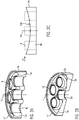
- the Figures 2A and 2B show oblique views of the inside of two cross sections through the central axis 14 of a flange plate 8a of a first example.
- the central axis 14 of the flange plate can also correspond, for example, to the central axis 12 of the tubular heat exchanger.
- the relief of the flange face 13a of the flange plate is exclusively concave in both cross-sections. So the curvature has the same sign everywhere, it is negative here.
- Receptacles 16 and passageways 9a are shown, the receptacles being extensions of the passageways and adapted to receive and secure the tubes.
- the receiving sockets are designed here, for example, in such a way that they all extend the same distance into the interior of the heat exchanger, which enables simple attachment.
- the receiving sockets can also be omitted. However, due to the contoured surface, it must then be taken into account that the openings of the passages are arranged at different positions along the central axis of the heat exchanger, so that the length of the tubes may also have to be adjusted.
- Figure 2C shows schematically the cross-sectional shape that corresponds to the cross-section in Figure 2A is equivalent to.
- the cross-sectional shape shown is advantageous in the case of an inlet-side flange plate, in particular in a cut surface parallel to the inflow direction, which is marked here by the arrow 15 .
- the position of the inlet is then also indicated by the arrow 15, with the arrow pointing away from the inlet.
- the preferred direction of flow along the flange plate is thus also illustrated with the arrow.
- the passages 9a and receiving sockets, as well as the rounded corners are only indicated with dashed lines and an exemplary imaginary continuation of the flange surface is also indicated.
- the shape shown can also be used for a flange plate on the outlet side, in particular in a cut surface parallel to the outflow direction.
- Figures 3A and 3B show oblique views of the inside of two cross sections through the central axis 14 of a flange plate 8b of a second example.
- the central axis 14 of the flange plate can also correspond, for example, to the central axis 12 of the tubular heat exchanger.
- the relief of the flange face 13b of the flange plate is exclusively convex in both cross-sections. So the curvature has the same sign everywhere, it is positive here.
- Figure 3C shows schematically the cross-sectional shape that corresponds to the cross-section in Figure 3A is equivalent to.
- the relief would have the same shape in all cross sections, including those not shown here, through the central axis of the flange plate.
- Figure 3C shows the cross-sectional shape schematically.
- the cross-sectional shape shown is advantageous in the case of an inlet-side flange plate, in particular in a cut surface parallel to the inflow direction, which is marked here by the arrow 15 .
- the position of the inlet is then also indicated by the arrow 15, with the arrow pointing away from the inlet.
- the preferred direction of flow along the flange plate is thus also illustrated with the arrow.
- the passages and receiving sockets, as well as the rounded corners are only indicated with dashed lines for better recognition of the shape and an exemplary imaginary continuation of the flange surface is also indicated.
- the shape shown can also be used for a flange plate on the outlet side, in particular in a cut surface parallel to the outflow direction.
- the Figures 4A and 4B show an oblique view of the inside of a cross section through the central axis 14 of a flange plate 8c of a third embodiment and a schematic cross-sectional shape.
- the central axis 14 of the flange plate can also correspond, for example, to the central axis 12 of the tubular heat exchanger.
- the relief of the flange surface 13c in cross section through the central axis 14 of the flange plate has a convex region 18b between two concave regions 18a, 18c in the region of the central axis. This means that a concave area 18a or 18c adjoins the central convex area 18b in both directions.
- the curvature of the two immediately adjacent to the receiving socket has the same sign for each receiving socket.
- the areas therefore each also extend beyond the corresponding receiving socket.
- the relief has the greatest height Hb of the relief in the convex region 18b , namely adjacent to the central one of the receiving sockets 16, through which the central axis runs.
- the relief here is not symmetrical.
- the curvature in the two concave areas is different.
- the concave portion 18a goes further down than the other concave portion 18c. That is, the minimum height H a in the concave portion 18a is lower than the minimum height H c in the concave portion 18c.
- the height H a can also be smaller than H c .
- the height of the relief may be less than or equal to the entire concave area 18a and/or the entire concave area 18c than the entire convex area 18b.
- Figure 4C Figure 12 shows schematically a similar structure with a central convex area 18b and two adjacent concave areas 18a and 18c, here being symmetrical with respect to the central axis 14 of the flange plate.
- H a and H c are equal in this example.
- the cross-sectional shape shown is advantageous in the case of an inlet-side flange plate, in particular in a cut surface parallel to the inflow direction, which is marked here by the arrow 15 .
- the position of the inlet is then also indicated by the arrow 15, with the arrow pointing away from the inlet.
- the preferred direction of flow along the flange plate is thus also illustrated with the arrow.
- the passages and receiving sockets, as well as the rounded corners are only indicated with dashed lines for better recognition of the shape and an exemplary imaginary continuation of the flange surface is also indicated. It goes without saying that the shape shown can also be used for a flange plate on the outlet side, in particular in a cut surface parallel to the outflow direction.
- FIG. 4D Another modification is shown schematically in Figure 4D shown.
- the flange plate is essentially as in Figure 4B formed, in which case the height H a is greater than the height H c .
- the height H a can also be smaller than H c .
- Figures 4A to 4D show a flow forms around the truncated cone formed by the convex area in the center of the flange plate. This will direct more liquid to the area opposite the entrance. This leads to an increased flow rate and thus less fouling and improved cleaning.
- Figures 4A and 4B show an asymmetric structure, which compared to the symmetric structure in Figure 4C a deflection of the flow in the direction of the z-axis is improved at the point where the two partial flows (around the truncated cone) meet.
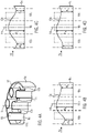
- FIG. 4E to 4H An example flange plate shown in the Figures 4E to 4H is shown combining different profiles, similar to the Figures 4B to 4D shown profiles.
- FIG 4E a top view of the flange plate is shown, in which a plane AA is shown, which runs perpendicularly to the inflow direction 15, here by way of example through the center of the flange plate and three sockets or passages. Furthermore, two planes BB and B'-B' are shown, which run parallel to the inflow direction, in each case in an area between the nozzles or passages and once in the area through the center of the flange plate, based on the flow direction.
- the flange plate cross-section is shown in the plane AA.
- the flange plate cross-section is shown in the plane BB.
- Figure 4H the flange plate cross-section is shown in the plane B'-B'.
- the value of quantity H b is equal to H 2 .
- a kind of flow saddle is formed.
- the flow saddle allows the flow to be better split, guided around the cone formed by the flange face and recombined opposite.
- FIG. 12 shows schematically another possible configuration of a flange plate 8d, in which the relief of the flange face 13d in cross-section through the central axis 14 of the flange plate has a concave area 19a and a convex area 19b located on different sides of the central axis of the flange plate.
- it is an upstream flange plate.
- the cross-sectional shape shown is particularly advantageous parallel to the inflow direction. That is, for example, here the concave area is arranged upstream of the convex area, with “upstream” referring to the inflow direction.
- the concave area 19a has the lowest height H a of the relief.
- the entire concave area is deeper than the entire convex area. That is, the height of the relief is smaller in the entire concave portion 19a than in the entire convex portion 19b in this example.
- a shape as in figure 5 shown is also conceivable for a flange plate on the outlet side. It is then advantageous if the convex area is arranged upstream of the concave area, "upstream" referring to the outflow direction.
- passages and receiving sockets are only indicated in dashed lines in the schematic representation for better recognition of the shape of the flange surface and an exemplary imaginary continuation of the flange surface is also indicated.
Landscapes
- Engineering & Computer Science (AREA)
- Physics & Mathematics (AREA)
- Thermal Sciences (AREA)
- Mechanical Engineering (AREA)
- General Engineering & Computer Science (AREA)
- Geometry (AREA)
- Chemical & Material Sciences (AREA)
- Manufacturing & Machinery (AREA)
- Materials Engineering (AREA)
- Heat-Exchange Devices With Radiators And Conduit Assemblies (AREA)
Description
- Die Erfindung betrifft einen Röhrenwärmetauscher nach dem Oberbegriff des Anspruchs 1. So ein Röhrenwärmetauscher ist aus
US 4 207 944 bekannt. - Röhrenwärmetauscher weisen in der Regel ein Gehäuse auf, in dem eine Mehrzahl von Röhren angeordnet ist, die im Wesentlichen parallel verlaufen. Im Betrieb strömt ein erstes Medium im Inneren der Röhren und ein zweites Medium, auch Sekundärmedium genannt, umströmt die Röhren im Inneren des Gehäuses.
- Der Bereich, in dem das erste Medium strömt, wird als Primärseite des Röhrenwärmetauschers bezeichnet und der Bereich des Wärmetauscherinneren, in dem das zweite Medium strömt, wird als Sekundärseite des Röhrenwärmetauschers bezeichnet.
- An mindestens einem Ende wird das Gehäuses mittels einer Flanschplatte abgeschlossen, die auch ein Anschlussstück zu anderen Prozessbereichen darstellt. Die Flanschplatte ist derart ausgebildet, dass sie Durchgänge aufweist, durch die das erste Medium aus dem Röhrenwärmetauscher ausströmen kann. Die Röhren können an diese Durchgänge angesetzt werden. In diesem Fall ist der Innendurchmesser der Durchgänge derart gewählt, dass dieser dem Innendurchmesser der Röhren entspricht. Alternativ können die Röhren in die Durchgänge hineingesteckt werden. In diesem Fall ist der Innendurchmesser der Durchgänge vorzugsweise derart gewählt, dass der Außendurchmesser der Röhren möglichst nur unwesentlich kleiner ist als der Innendurchmesser der Durchgänge. Durch Verschweißen der Röhren und der Flanschplatte werden die Röhren befestigt und die Verbindung zwischen Flanschplatte und Röhren wird abgedichtet. Somit ermöglicht die Flanschplatte, die Röhren stabil zu positionieren, die beiden Medien zuverlässig voneinander zu trennen und das Innere des Röhrenwärmetauschers nach außen hin abzudichten.
- Bei diesen Röhrenwärmetauschern ist dabei die Oberfläche der Innenseite der Flanschplatte eben und im Wesentlichen senkrecht zu den Röhren.
- Als Alternative ist bekannt, hohlzylinderförmige Verlängerungen der Durchgänge zum Wärmetauscherinneren hin vorzusehen, deren Innenwand am Wärmetauscherinneren zugewandten Ende eine Stufe aufweist. Die Stufe ist so geformt, dass der dem Wärmetauscherinneren zugewandte Abschnitt der Verlängerung einen Innendurchmesser aufweist, der unwesentlich größer als der Außendurchmesser der Röhre ist, und der andere Abschnitt der Verlängerung einen Innendurchmesser aufweist, der dem Innendurchmesser der Röhre und des Durchgangs entspricht. Das Ende jeder Röhre wird der Seitenwand der jeweiligen Verlängerung verschweißt.
- Auch bei diesen Röhrenwärmetauschern ist, mit Ausnahme der Seitenwände der Verlängerung, die Oberfläche der Innenseite der Flanschplatte eben und im Wesentlichen senkrecht zu den Röhren. Besagte Seitenwände verlaufen typischerweise parallel zu den Röhren.
- Mit anderen Worten haben bekannte Röhrenwärmetauscher eine oder mehrere Flanschplatten, beispielsweise als Deckel- und/oder Bodenstück, welche auf der dem Wärmetauscherinneren zugewandten Seite (Sekundärseite) eine im Wesentlichen ebene Fläche senkrecht zu den Röhren, und somit typischerweise auch zum Gehäuse (auch Mantelrohr genannt), aufweisen.
- Sowohl die bekannten als auch die im Folgenden beschriebenen erfindungsgemäßen Röhrenwärmetauscher können beispielsweise so ausgebildet sein, dass das Sekundärmedium durch einen Einlauf in das Wärmetauscherinnere strömt, wo es entlang der Röhren zu einem Auslauf, durch den es das Wärmetauscherinnere verlässt, strömt und dabei die Röhren umströmt. Die Strömungsrichtung im Zulauf und/oder im Ablauf, also die Zuströmrichtung bzw. Ausströmrichtung, kann dabei insbesondere senkrecht zu der Längsrichtung der Röhren sein. Das heißt, die Längsrichtung von Rohren oder Stutzen, die den Einlauf bzw. Auslauf bilden kann senkrecht zu der Längsrichtung der Röhren sein.
- Bei der bekannten Konstruktionsweise können sich Totzonen ergeben, insbesondere in einem Bereich diametral zum sekundärseitigen Eintritt- bzw. Austritt. Mit dem Bereich "diametral zum sekundärseitigen Eintritt- bzw. Austritt" ist jener gemeint, der gegenüber dem Zulauf bzw. Ablauf des Sekundärmediums liegt. Das kann insbesondere den dem Zulauf bzw. Ablauf gegenüberliegenden Bereich der Seitenwand des Wärmetauscherinneren umfassen. Auch im zur Flanschplatte gewandten Bereich der Aushalsung des Zulaufs bzw. Auslaufs kann es einen weniger gut durchströmten Bereich geben.
- Das Problem wird verstärkt, wenn die Flanschplatte ein Bodenstück bildet und die ebene Fläche waagerecht angeordnet ist. In den Totzonen sind die Strömungsgeschwindigkeiten des zweiten Mediums niedriger als in anderen Bereichen. Man bezeichnet diese Bereiche auch als Strömungsschatten. In diesen Bereichen kann sich wegen geringerer Durchspülung Produkt ablagern bzw. anbacken. Außerdem ist auch die Reinigung, beispielsweise während eines Clean-In-Place (CIP)-Prozesses, dort erschwert. Somit wird Fouling beschleunigt. Bei Produktwärmetauschern, bei denen das zweite Medium, welches die Röhren umströmt, ein Produkt darstellt, besteht dann auch die Gefahr, dass das Produkt verunreinigt wird.
- Ein weiteres Problem besteht darin, dass das zweite Medium in den Bereichen der Totzonen länger verweilt als in anderen. Man erhält also ein breiteres Verweilzeitspektrum. Dieses führt zu einem ungleichmäßigen Wärmeaustausch.
- Es ist also eine Aufgabe der vorliegenden Erfindung einen Röhrenwärmetauscher bereitzustellen, der Ablagerungen und Fouling reduziert und gleichmäßige Wärmetauscheigenschaften und ein verbessertes Reinigungsverhalten aufweist.
- Die Aufgabe wird durch den Gegenstand des Anspruchs 1 gelöst.
- Mit anderen Worten weist die Flanschplatte eine unebene, also dreidimensionale Flanschfläche auf der Sekundärseite auf, beispielsweise eine einfach oder mehrfach gewölbte Fläche. Eine solche Konfiguration ermöglicht, gezielt die Strömung im Bereich um die Flanschfläche zu beeinflussen, insbesondere in ausgewählten Bereichen zu beschleunigen. Die Flanschplatte hat also eine Flanschfläche mit Erhebungen bzw. Formflächen.
- Dabei können die tiefsten Punkte der zwischen den Stutzen liegenden Abschnitte der Flanschfläche zumindest teilweise auf unterschiedlichen Ebenen senkrecht zur Erstreckungsrichtung der Aufnahmestutzen bzw. den Durchgängen liegen. Das heißt, dass beispielsweise in einem Querschnitt mit einer Schnittebene parallel zu besagter Erstreckungsrichtung, der durch einen ersten, zweiten und dritten Aufnahmestutzen (bzw. Durchgang) verläuft, die minimale Höhe des Reliefs zwischen einem ersten und einem zweiten Aufnahmestutzen (bzw. Durchgang) einen anderen Wert aufweist als die minimale Höhe des Reliefs zwischen dem zweiten und dem dritten Aufnahmestutzen bzw. Durchgang.
- Die zum Wärmetauscherinneren weisende Oberfläche der Flanschplatte kann insbesondere derart ausgebildet sein, dass mehr als 30 %, insbesondere mehr als 40 %, insbesondere mehr als 50 % der zum Wärmetauscherinneren weisende Oberfläche der Flanschplatte eine Krümmung ungleich 0 aufweisen. Alternativ oder zusätzlich kann die zum Wärmetauscherinneren weisende Oberfläche der Flanschplatte insbesondere derart ausgebildet sein, dass mehr als 30 %, insbesondere mehr als 40 %, insbesondere mehr als 50 % der zum Wärmetauscherinneren weisende Oberfläche der Flanschplatte eine Steigung ungleich 0 bezüglich einer zu den Aufnahmestutzen bzw. Durchgängen senkrechten Ebene aufweisen.
- Bei der beanspruchten Konfiguration der Flanschplatte kann sich die Strömung an der Flanschplatte besser ausbilden. Die Flanschfläche kann insbesondere derart konturiert sein, dass die oben beschriebenen Totzonen, insbesondere im Bereich gegenüber der Eintritts- und Austrittsöffnung des Sekundärraums sowie direkt im Strömungsschatten am Ein- und Austritt, vermieden werden. Insbesondere können die Konturierungen so ausgebildet sein, dass rechte Winkel vermieden werden.
- Die Flanschplatte ist also derart ausgebildet, dass die Strömung eines Mediums (zweites Medium) verbessert wird, insbesondere in den Totzonen die Strömungsgeschwindigkeit erhöht wird. Durch eine Erhöhung der Strömungsgeschwindigkeit in den Totzonen wird die Belagsbildung und Menge an Ablagerungen reduziert und die Reinigungswirkung verbessert. Außerdem wird das Verweilzeitspektrum schmaler und die Wärmetauscheigenschaften werden gleichmäßiger.
- Die Flanschplatte ist derart mit den Röhren verbunden, dass ein Medium (erstes Medium) durch die Durchgänge in die Röhren einströmen oder aus den Röhren ausströmen kann.
- Die Flanschplatte kann eine Mehrzahl von im Wesentlichen hohlzylinderförmigen Aufnahmestutzen jeweils zum Aufnehmen einer der Röhren des Röhrenwärmetauschers auf der dem Wärmetauscherinneren zugewandten Seite umfassen, wobei eine Außenseite der Aufnahmestutzen in die Flanschfläche mündet. Dabei ist die Flanschfläche die Ansatzfläche der Außenfläche der Aufnahmestutzen. Die Aufnahmestutzen werden auch als Ansätze für die Schweißnaht bezeichnet. Die Aufnahmestutzen können auch als Verlängerungen der Durchgänge betrachtet werden.
- In einer besonderen Ausführungsform ist der Abstand zwischen den Aufnahmestutzen und der primärseitigen Fläche der Flanschplatte für alle Aufnahmestutzen konstant.
- Der Innendurchmesser der Aufnahmestutzen kann insbesondere derart gewählt sein, dass die Röhren in dem Aufnahmestutzen aufgenommen werden können, wobei der Außendurchmesser der Röhren nur unwesentlich kleiner ist als der Innendurchmesser der Aufnahmestutzen. Durch Verschweißen der Röhren und der Aufnahmestutzen werden die Röhren befestigt und die Verbindung zwischen Aufnahmestutzen und Röhren wird abgedichtet. In einer alternativen Ausführungsform können die Röhren auch durch die Flanschplatte gesteckt sein. Mit anderen Worten können sich die Röhren durch die gesamte Dicke der Flanschplatte erstrecken.
- Ein Relief der Flanschfläche im Querschnitt, insbesondere durch die Mittelachse der Flanschplatte, ist einfach oder mehrfach gekrümmt. Das heißt, die Krümmung kann in einem oder mehreren Bereichen des Reliefs ungleich Null sein. Das Relief kann jedoch auch Bereiche ohne Krümmung aufweisen. Die Mittelachse ist dabei eine Achse, die parallel zu den Durchgängen und durch den geometrischen Schwerpunkt der Grundfläche verläuft, bei einer kreisförmigen Grundfläche beispielsweise durch den Mittelpunkt des Kreises.
- Als ein Bereich mit einem bestimmten Krümmungsvorzeichen, sprich ein konvexer oder konkaver Bereich, ist in dieser Anmeldung ein zusammenhängender Abschnitt des Reliefs zu verstehen, in dem das Krümmungsvorzeichen gleich ist, sprich, der zusammenhängende Abschnitt des Reliefs zwischen zwei benachbarten Wendepunkten. Außerdem werden auch zwei benachbarte Abschnitte, die sich an einen Durchgang oder einen Aufnahmestutzen anschließen und das gleiche Krümmungsvorzeichen haben als Teil desselben Bereichs betrachtet. Das bedeutet, dass ein Bereich benachbarte Abschnitte mit gleichem Krümmungsvorzeichen umfassen kann, insbesondere auch benachbarte Abschnitte mit gleichem Krümmungsvorzeichen, die durch einen Aufnahmestutzen oder einen Durchgang getrennt sind. Mit anderen Worten kann sich ein Bereich über einen Durchgang bzw. Aufnahmestutzen hinweg erstrecken, was der Fall ist, wenn sich an beiden Seiten des Aufnahmestutzens bzw. des Durchgangs ein Abschnitt mit gleichem Krümmungsvorzeichen an den Aufnahmestutzen bzw. den Durchgang anschließt.
- Die Steigung in einem, mehreren oder allen Bereichen des Reliefs kann ungleich Null sein.
- Mit Querschnitt ist hier ein Querschnitt durch eine Fläche gemeint, die parallel zu den Durchgängen in der Flanschplatte bzw. den Röhren verläuft. Das Relief beschreibt den Höhenverlauf der Flanschfläche in dem jeweiligen Querschnitt. Es kann auch als Profil bezeichnet werden. Dabei kann die Höhe bezogen auf eine beliebige Referenzfläche, die senkrecht zu der Querschnittsfläche ist und zum Wärmetauscheräußeren hin derart angeordnet ist, dass sie die Flanschfläche nicht schneidet, definiert werden. Wenn die der Flanschfläche gegenüberliegende Seite der Flanschplatte, sprich die zum Wärmetauscheräußeren weisende Seite, eben ist, kann diese als Referenzfläche verwendet werden.
- Die in dieser Anmeldung beschriebenen Aussagen zu den Krümmungen und Steigungen des Reliefs können grundsätzlich für Reliefs beliebig gewählter Querschnitte gelten. Insbesondere können die Aussagen beispielsweise für einen, mehrere, oder alle Querschnitte durch die Mittelachse gelten. In letzteren Fall ergibt sich dann eine Rotationssymmetrie. Die Aussagen können beispielsweise auch für alle parallelen Querschnitte entlang einer bestimmten Richtung gelten.
- Das Relief weisst mindestens einen konkaven und mindestens einen konvexen Bereich auf. Das heißt, dass das Relief mindestens einen Bereich mit positiver und einen Bereich mit negativer Krümmung aufweisen kann, sprich mindestens zwei Bereiche mit entgegengesetztem Krümmungsvorzeichen. Der Betrag der Krümmung kann für das gesamte Relief gleich oder an verschiedenen Stellen des Reliefs unterschiedlich sein.
- Das Relief kann einen konvexen Bereich zwischen zwei konkaven Bereichen aufweisen. Dabei kann insbesondere der konvexe Bereich die größte Höhe des Reliefs aufweisen, insbesondere an der Mittelachse der Flanschplatte oder unmittelbar angrenzend an einen Aufnahmestutzen für eine der Röhren oder einen Durchgang, durch den die Mittelachse verläuft. In einer weiteren Ausführungsform kann die Höhe des konkaven Bereichs die größte Höhe des Reliefs aufweisen.
- Insbesondere kann eine Flanschplatte eine einlaufseitige Flanschplatte sein und derart ausgebildet und angeordnet sein, dass ein solches Relief entlang der Einströmrichtung des Sekundärmediums in das Wärmetauscherinnere im bestimmungsgemäßen Gebrauch vorliegt.
- Bei einer derartigen Konfiguration bildet sich eine Strömung um den durch den konvexen Bereich gebildeten Kegel in der Mitte der Flanschplatte aus. Dadurch wird mehr Flüssigkeit in den Bereich diametral zum sekundärseitigen Eintritt geführt, beispielsweise in einen Bereich der Flanschplatte und/oder Seitenwand gegenüber dem Zulauf. Dies führt zu einer erhöhten Strömungsgeschwindigkeit und somit zu geringerem Fouling und verbesserter Reinigung.
- Es versteht sich, dass die Flanschplatte alternativ eine auslaufseitige Flanschplatte sein und derart ausgebildet und angeordnet sein kann, dass ein solches Relief entlang der Ausströmrichtung des Sekundärmediums aus dem Wärmetauscherinneren im bestimmungsgemäßen Gebrauch vorliegt.
- Es ist ebenfalls denkbar, dass sowohl die einlaufseitige als auch die auslaufseitige Flanschplatte des Wärmetauschers entsprechend ausgebildet sind.
- Die minimale Höhe des Reliefs in einem ersten der beiden konkaven Bereiche kann niedriger sein als die minimale Höhe des Reliefs in dem anderen der beiden konkaven Bereiche. Insbesondere kann der gesamte konkave Bereich eine geringere Höhe haben als der gesamte konvexe Bereich.
- Die Flanschplatte kann eine einlaufseitige Flanschplatte sein und der erste der beiden konkaven Bereiche kann bezüglich des anderen der beiden konkaven Bereiche stromaufwärts angeordnet sein oder die Flanschplatte kann eine auslaufseitige Flanschplatte sein und der zweite der beiden konkaven Bereiche kann bezüglich des anderen der beiden konkaven Bereiche stromaufwärts angeordnet sein. Stromaufwärts bezieht sich dabei auf die oben beschriebene Ein- bzw. Ausströmrichtung des Sekundärmediums. Mit anderen Worten kann im Falle einer einlaufseitigen Flanschplatte der erste Bereich näher am Einlauf sein als der zweite Bereich und im Falle einer auslaufseitigen Flanschplatte kann der erste Bereich näher am Auslauf sein als der zweite Bereich. Der Vorteil hiervon ist, dass ein besonders vorteilhaftes Strömungsprofil erreicht werden kann.
- Das Relief kann, insbesondere genau, einen konvexen Bereich und, insbesondere genau, einen konkaven Bereich aufweisen, die zumindest teilweise auf verschiedenen Seiten der Mittelachse der Flanschplatte angeordnet sind. Dabei kann die Höhe des Reliefs im konkaven Bereich ein Minimum und im konvexen Bereich ein Maximum aufweisen. Insbesondere kann im Falle einer einlaufseitigen Flanschplatte der konkave Bereich bezüglich des konvexen Bereichs stromaufwärts angeordnet sein oder im Falle einer auslaufseitigen Flanschplatte der konvexe Bereich bezüglich des konkaven Bereichs stromaufwärts angeordnet sein. Stromaufwärts bezieht sich dabei jeweils auf die oben beschriebene Ein- bzw. Ausströmrichtung des Sekundärmediums. Mit anderen Worten kann im Falle einer einlaufseitigen Flanschplatte der konkave Bereich näher am Einlauf sein als der konvexe Bereich und im Falle einer auslaufseitigen Flanschplatte kann der konkave Bereich näher am Auslauf sein als der konvexe Bereich.
- Die oben beschriebene Anordnung ermöglicht ebenfalls ein besonders vorteilhaftes Strömungsprofil.
- Die Flanschfläche kann bezogen auf die Mittelachse der Flanschplatte rotationssymmetrisch und/oder achsensymmetrisch ausgeführt sein. Das bedeutet im Falle einer Rotationssymmetrie, dass das Relief für jeden Querschnitt durch die Mittelachse der Flanschplatte gleich ist. Im Falle der Achsensymmetrie bedeutet dies, dass das Relief für jeden Querschnitt durch die Flanschplatte achsensymmetrisch bezogen auf die Mittelachse ist. Andere Symmetrien der Flanschfläche sind ebenfalls denkbar, insbesondere eine Spiegelsymmetrie bezogen auf eine auf der Flanschplatte senkrecht stehenden Ebene, in der die Mittelachse der Flanschplatte verläuft.
- Die Flanschfläche kann, beispielsweise bezogen auf die Mittelachse der Flanschplatte, asymmetrisch ausgebildet sein, insbesondere derart asymmetrisch ausgebildet sein, dass die Strömungsgeschwindigkeiten im Strömungsschatten erhöht werden.
- Eine zum Wärmetauscheräußeren weisende Fläche der Flanschplatte kann ebenfalls, beispielsweise wie oben beschrieben, konturiert sein.
- Die Flanschplatte kann mittels eines elektrochemischen Abtragungsverfahrens oder eines additiven oder generativen Fertigungsverfahrens, insbesondere 3D-Druck, hergestellt sein. Diese Fertigungsverfahren ermöglichen, kostengünstig eine Flanschplatte mit komplexer Geometrie herzustellen, ohne dabei die Oberflächengüte herabzusetzen.
- Die Erfindung betrifft auch eine Anlage zum Kurzzeiterhitzen von Getränkeprodukten umfassend einen der oben beschriebenen Röhrenwärmetauscher, derart ausgebildet, dass auf der Primärseite des Röhrenwärmetauschers bereits erhitztes Produkt und auf der Sekundärseite des Röhrenwärmetauschers zu erhitzendes Produkt fließt.
- Wie oben erläutert, wird dabei der Bereich, in dem im bestimmungsgemäßen Gebrauch das erste Medium strömt, als Primärseite des Röhrenwärmetauschers bezeichnet und der Bereich des Wärmetauscherinneren, in dem das zweite Medium strömt, als Sekundärseite des Röhrenwärmetauschers.
- Die Anlage kann eine Abfüllanlage umfassen, insbesondere eine Getränkeabfüllanlage, zur Abfüllung von Behältern, insbesondere Getränkebehältern wie Fässer oder Flaschen.
- Weitere Merkmale und Vorteile werden nachfolgend anhand der beispielhaften Figuren erläutert. Dabei zeigen:
- Figur 1
- eine schematische, nicht maßstabsgetreue Querschnittsansicht eines Röhrenwärmetauschers;
- Figuren 2A bis 2C
- schematische, nicht maßstabsgetreue Ansichten einer Flanschplatte nach einem ersten Beispiel nicht gemäß der Erfindung; und
- Figuren 3A bis 3C
- schematische, nicht maßstabsgetreue Ansichten einer Flanschplatte nach einem zweiten Beispiel nicht gemäß der Erfindung;
- Figuren 4A bis 4H
- schematische, nicht maßstabsgetreue Ansichten einer Flanschplatte gemäß einer dritten Ausführungsform und Abwandlungen dieser Flanschplatte; und
- Figur 5
- einen schematischen, nicht maßstabsgetreuen Querschnitt einer Flanschplatte gemäß einer vierten Ausführungsform.
-
Figur 1 zeigt einen Querschnitt durch einen Röhrenwärmetauscher 1. Der Röhrenwärmetauscher umfasst einen Zulauf 2 und einen Ablauf 3 für ein zweites Medium und einen Zulauf 4 und einen Ablauf 5 für ein erstes Medium. Außerdem umfasst der Röhrenwärmetauscher ein Gehäuse 6 und innerhalb des Gehäuses angeordnete, parallel zueinander beabstandet angeordnete Röhren 7. Der Röhrenwärmetauscher umfasst hier zwei Flanschplatten 8, die jeweils Durchgänge 9 für die Röhren aufweisen. Die Röhren können sich dabei jeweils in einen Durchgang hinein (hier zur Vereinfachung nicht im Detail dargestellt) erstrecken und sind an der Flanschplatte befestigt, typischerweise verschweißt. - Die Durchgänge erstrecken sich jeweils durch die gesamte Flanschplatte. Durch diese Anordnung kann das erste Medium aus dem Zulauf 4 durch die Durchgänge der einen Flanschplatte, die Röhren 7 und die Durchgänge in der anderen Flanschplatte in den Ablauf 5 strömen. Die Strömungsrichtung ist hier mit dem Pfeil 10 gekennzeichnet.
- Der Zulauf 2 und Ablauf 3 für das zweite Medium sind fluidisch mit dem durch das Gehäuse und die Flanschplatten begrenzten Innenraum 1a des Röhrenwärmetauschers (auch als Wärmetauscherinneres bezeichnet) verbunden. Durch diese Anordnung kann das zweite Medium, beispielsweise entlang der Strömungsrichtung 11, durch den Innenraum des Röhrenwärmetauschers strömen und, beispielsweise entlang der Einströmrichtung bzw. Ausströmrichtung, welche hier parallel sind und durch den Pfeil 15 gekennzeichnet sind, in das Wärmetauscherinnere hinein bzw. aus dem Wärmetauscherinneren heraus. Da die Röhren ebenfalls im Innenraum angeordnet sind, umströmt das zweite Medium dann die Röhren, so dass ein Wärmeaustausch zwischen dem ersten und dem zweiten Medium erfolgt.
- Zulauf und Ablauf können jeweils auch vertauscht werden. Insbesondere können Zulauf und Ablauf nur des ersten oder nur des zweiten Mediums geändert werden. Im Gegensatz zu den in der Figur gezeigten entgegengesetzten Strömungsrichtungen im Bereich des Wärmeaustauschs, würden die beiden Medien dann in die gleiche Richtung strömen.
- Das Gehäuse und die Flanschplatten können (hier aufgrund der Perspektive nicht ersichtlich) eine im Wesentlichen kreisförmige Grundfläche haben. Das Gehäuse kann insbesondere hohlzylinderförmig ausgebildet sein. Die Röhren können darin, wie in der Figur dargestellt, beispielsweise in regelmäßigen Abständen angeordnet sein. Dies ist aber nicht zwingend der Fall. Alternativ oder zusätzlich können die Röhren konzentrisch um die Mittelachse 12 des Röhrenwärmetauschers, beispielsweise des Gehäuses, und/oder einer Mittelachse 14 mindestens einer der Flanschplatten, angeordnet sein. Optional kann die Mittelachse auch durch eine der Röhren verlaufen und die übrigen Röhren konzentrisch um diese Röhre angeordnet sein, wie in
Figur 1 gezeigt. Die Mittelachse 14 einer oder beider Flanschplatten kann insbesondere mit der Mittelachse 12 des Röhrenwärmetauschers übereinstimmen. - Erfindungsgemäß ist bei mindestens einer der beiden Flanschplatten eine dem Wärmetauscherinneren zugewandte Flanschfläche konturiert, was in
Figur 1 für beide Flanschplatten angedeutet ist. Mögliche Ausführungen für Flanschplatten mit einer konturierten Flanschfläche werden im Folgenden beschrieben und sind in denFiguren 2 bis 5 gezeigt. Es versteht sich jedoch, dass auch Flanschplatten mit anderweitig konturierten Flanschflächen verwendet werden können. - Die
Figuren 2A und 2B zeigen Schrägansichten auf die Innenseite zweier Querschnitte durch die Mittelachse 14 einer Flanschplatte 8a eines ersten Beispiels. Die Mittelachse 14 der Flanschplatte kann, wie oben erläutert, beispielsweise auch der Mittelachse 12 des Röhrenwärmetauschers entsprechen. In dieser Ausführungsform ist das Relief der Flanschfläche 13a der Flanschplatte in beiden Querschnitten ausschließlich konkav. Die Krümmung hat also überall das gleiche Vorzeichen, sie ist hier negativ. Insbesondere kann hier auch eine Rotationssymmetrie um die Mittelachse der Flanschplatte vorliegen. Dann hätte das Relief in allen, auch den hier nicht gezeigten, Querschnitten durch die Mittelachse der Flanschplatte die gleiche Form. - In den
Figuren 2A bis 2C sind Aufnahmestutzen 16 und Durchgänge 9a gezeigt, wobei die Aufnahmestutzen Verlängerungen der Durchgänge darstellen und zum Aufnehmen und Befestigen der Röhren ausgebildet sind. Die Aufnahmestutzen sind hier beispielhaft derart ausgebildet, dass sie sich alle gleich weit ins Wärmetauscherinnere erstrecken, was eine einfache Befestigung ermöglicht. - Die Aufnahmestutzen können auch weggelassen werden. Dann ist jedoch aufgrund der konturierten Oberfläche zu berücksichtigen, dass die Öffnungen der Durchgänge an verschiedenen Positionen entlang der Mittelachse des Wärmetauschers angeordnet sind, so dass unter Umständen auch die Länge der Röhren angepasst werden muss.
- Man kann in den
Figuren 2A bis 2C erkennen, dass der Übergang zwischen den Aufnahmestutzen und der Flanschfläche kein scharfes Eck bildet, sondern abgerundet ist. Diese Abrundung ist zum Bestimmen der Krümmung und Steigung der Flanschfläche in allen hier beschriebenen Beispielen außer Acht zu lassen. Dies gilt analog für den Übergang der Flanschfläche in den Rand 17, wo ebenfalls ein abgerundetes Eck vorliegen kann. -
Figur 2C zeigt schematisch die Querschnittsform, die dem Querschnitt inFigur 2A entspricht. Die gezeigte Querschnittsform ist bei einer zulaufseitigen Flanschplatte, insbesondere in einer Schnittfläche parallel zur Einströmrichtung, die hier mit dem Pfeil 15 gekennzeichnet ist, vorteilhaft. Mit dem Pfeil 15 ist dann auch die Lage des Einlaufs angedeutet, wobei der Pfeil vom Einlauf weg zeigt. Somit wird mit dem Pfeil auch die Vorzugsströmungsrichtung entlang der Flanschplatte verdeutlicht. In der schematischen Darstellung sind zur besseren Erkennbarkeit der Form der Flanschfläche die Durchgänge 9a und Aufnahmestutzen, sowie die abgerundeten Ecken, lediglich gestrichelt angedeutet und eine beispielhafte gedankliche Fortsetzung der Flanschfläche ist ebenfalls angedeutet. Es versteht sich, dass die gezeigte Form auch für eine ablaufseitige Flanschplatte verwendet werden kann, insbesondere in einer Schnittfläche parallel zur Ausströmrichtung. -
Figuren 3A und 3B zeigen Schrägansichten auf die Innenseite zweier Querschnitte durch die Mittelachse 14 einer Flanschplatte 8b eines zweiten Beispiels. Die Mittelachse 14 der Flanschplatte kann, wie oben erläutert, beispielsweise auch der Mittelachse 12 des Röhrenwärmetauschers entsprechen. In diesem Beispiel ist das Relief der Flanschfläche 13b der Flanschplatte in beiden Querschnitten ausschließlich konvex. Die Krümmung hat also überall das gleiche Vorzeichen, sie ist hier positiv. Insbesondere kann hier auch eine Rotationssymmetrie um die Mittelachse der Flanschplatte vorliegen. Dann hätte das Relief in allen, auch den hier nicht gezeigten, Querschnitten durch die Mittelachse der Flanschplatte die gleiche Form.Figur 3C zeigt schematisch die Querschnittsform, die dem Querschnitt inFigur 3A entspricht. Insbesondere kann hier auch eine Rotationssymmetrie um die Mittelachse der Flanschplatte vorliegen. Dann hätte das Relief in allen, auch den hier nicht gezeigten, Querschnitten durch die Mittelachse der Flanschplatte die gleiche Form. -
Figur 3C zeigt schematisch die Querschnittsform. Die gezeigte Querschnittsform ist bei einer zulaufseitigen Flanschplatte, insbesondere in einer Schnittfläche parallel zur Einströmrichtung, die hier mit dem Pfeil 15 gekennzeichnet ist, vorteilhaft. Mit dem Pfeil 15 ist dann auch die Lage des Einlaufs angedeutet, wobei der Pfeil vom Einlauf weg zeigt. Somit wird mit dem Pfeil auch die Vorzugsströmungsrichtung entlang der Flanschplatte verdeutlicht. In der schematischen Darstellung sind zur besseren Erkennbarkeit der Form die Durchgänge und Aufnahmestutzen, sowie die abgerundeten Ecken, lediglich gestrichelt angedeutet und eine beispielhafte gedankliche Fortsetzung der Flanschfläche ist ebenfalls angedeutet. Es versteht sich, dass die gezeigte Form auch für eine ablaufseitige Flanschplatte verwendet werden kann, insbesondere in einer Schnittfläche parallel zur Ausströmrichtung. - Die
Figuren 4A und 4B zeigen eine Schrägansicht auf die Innenseite eines Querschnitts durch die Mittelachse 14 einer Flanschplatte 8c einer dritten Ausführungsform und eine schematische Querschnittsform. Die Mittelachse 14 der Flanschplatte kann, wie oben erläutert, beispielsweise auch der Mittelachse 12 des Röhrenwärmetauschers entsprechen. - Bei der hier gezeigten Flanschplatte weist das Relief der Flanschfläche 13c im Querschnitt durch die Mittelachse 14 der Flanschplatte im Bereich der Mittelachse einen konvexen Bereich 18b zwischen zwei konkaven Bereichen 18a, 18c auf. Das heißt, an den zentralen konvexen Bereich 18b schließt sich in beide Richtungen je ein konkaver Bereich 18a bzw. 18c an.
- Wie hier erkennbar ist, hat für jeden Aufnahmestutzen die Krümmung der beiden unmittelbar an den Aufnahmestutzen angrenzt das gleiche Vorzeichen. Daher erstrecken sich die Bereiche jeweils auch über den entsprechenden Aufnahmestutzen hinweg.
- Im hier gezeigten Beispiel weist das Relief in dem konvexen Bereich 18b die größte Höhe Hb des Reliefs auf, nämlich angrenzend an den mittleren der Aufnahmestutzen 16, durch den die Mittelachse verläuft.
- Das Relief ist hier nicht symmetrisch. Die Krümmung in den beiden konkaven Bereichen ist unterschiedlich groß. Der konkave Bereich 18a geht zudem weiter nach unten als der andere konkave Bereich 18c. Das heißt, die minimale Höhe Ha im konkaven Bereich 18a ist niedriger als die minimale Höhe Hc im konkaven Bereich 18c. Alternativ kann aber auch die Höhe Ha kleiner als Hc sein. Die Höhe des Reliefs kann im gesamten konkaven Bereich 18a und/oder im gesamten konkaven Bereich 18c kleiner oder gleich sein als im gesamten konvexen Bereich 18b.
-
Figur 4C zeigt schematisch eine ähnliche Struktur mit einem mittigen konvexen Bereich 18b und zwei angrenzenden konkaven Bereichen 18a und 18c, wobei hier eine Symmetrie bezüglich der Mittelachse 14 der Flanschplatte vorliegt. Somit sind insbesondere Ha und Hc in diesem Beispiel gleich. - Die gezeigte Querschnittsform ist bei einer zulaufseitigen Flanschplatte, insbesondere in einer Schnittfläche parallel zur Einströmrichtung, die hier mit dem Pfeil 15 gekennzeichnet ist, vorteilhaft. Mit dem Pfeil 15 ist dann auch die Lage des Einlaufs angedeutet, wobei der Pfeil vom Einlauf weg zeigt. Somit wird mit dem Pfeil auch die Vorzugsströmungsrichtung entlang der Flanschplatte verdeutlicht. In den schematischen Darstellungen sind zur besseren Erkennbarkeit der Form die Durchgänge und Aufnahmestutzen, sowie die abgerundeten Ecken, lediglich gestrichelt angedeutet und eine beispielhafte gedankliche Fortsetzung der Flanschfläche ist ebenfalls angedeutet. Es versteht sich, dass die gezeigte Form auch für eine auslaufseitige Flanschplatte verwendet werden kann, insbesondere in einer Schnittfläche parallel zur Ausströmrichtung.
- Eine weitere Abwandlung ist schematisch in
Figur 4D gezeigt. Die Flanschplatte ist im Wesentlichen wie inFigur 4B ausgebildet, wobei hier die Höhe Ha größer ist als die Höhe Hc. Alternativ kann aber auch die Höhe Ha kleiner als Hc sein. - Bei den Varianten, die in
Figuren 4A bis 4D gezeigt sind, bildet sich eine Strömung um den durch den konvexen Bereich gebildeten Kegelstumpf in der Mitte der Flanschplatte aus. Dadurch wird mehr Flüssigkeit in den Bereich gegenüber des Eintritts geführt. Dies führt zu einer erhöhten Strömungsgeschwindigkeit und somit zu geringerem Fouling und verbesserter Reinigung.Figuren 4A und 4B zeigen dabei eine asymmetrische Struktur, die im Vergleich zu der symmetrischen Struktur inFigur 4C eine Umlenkung der Strömung in Richtung z-Achse an der Stelle verbessert, an der die beiden Teilströmungen (um den Kegelstumpf) aufeinandertreffen. - Eine beispielhafte Flanschplatte, die in den
Figuren 4E bis 4H gezeigt ist, kombiniert verschiedene Profile, ähnlich zu denFiguren 4B bis 4D gezeigten Profilen. - In
Figur 4E ist eine Draufsicht auf die Flanschplatte gezeigt, darin ist eine Ebene A-A gezeigt, die senkrecht zur Einströmrichtung 15, hier beispielhaft durch die Mitte der Flanschplatte und drei Stutzen bzw. Durchgänge, verläuft. Weiterhin sind zwei Ebenen B-B und B'-B' gezeigt, die parallel zur Einströmrichtung verlaufen und zwar jeweils in einem Bereich zwischen den Stutzen bzw. Durchgängen und einmal im Bereich durch die Mitte der Flanschplatte, bezogen auf die Strömungsrichtung. InFigur 4F ist der Flanschplattenquerschnitt in der Ebene A-A gezeigt. InFigur 4G ist der Flanschplattenquerschnitt in der Ebene B-B gezeigt. InFigur 4H ist der Flanschplattenquerschnitt in der Ebene B'-B' gezeigt. - In diesem Beispiel sind die Werte der oben beschriebenen Größen Ha und Hc im Schnitt B'-B' gleich, wobei Ha = Hc = T1. Im Schnitt B-B sind die Werte von Ha und Hc ebenfalls gleich, wobei Ha = Hc = T2. Im Schnitt A-A sind die Werte von Ha und Hc ebenfalls gleich, wobei Ha = Hc = T3. Dabei ist T1 > T2 > T3. In diesem Beispiel ist der Wert der oben beschriebene Größe Hb im Schnitt B'-B' gleich dem Wert der Größe Hb im Schnitt A-A, wobei Hb = H1. Im Schnitt B-B ist der Wert der Größe Hb gleich H2. Dabei ist H1 > H2.
- Bei der in den
Figuren 4E bis 4H gezeigten Konfiguration wird eine Art Strömungssattel ausgebildet. Der Strömungssattel ermöglicht, dass die Strömung besser aufgeteilt, um den durch die Flanschfläche gebildeten Kegel geführt und gegenüber wieder zusammengeführt wird. -
Figur 5 zeigt schematisch eine weitere mögliche Konfiguration einer Flanschplatte 8d, bei der das Relief der Flanschfläche 13d im Querschnitt durch die Mittelachse 14 der Flanschplatte einen konkaven Bereich 19a und einen konvexen Bereich 19b aufweist, die auf verschiedenen Seiten der Mittelachse der Flanschplatte angeordnet sind. In diesem Beispiel handelt es sich um eine zulaufseitige Flanschplatte. Wie durch den Pfeil 15 angedeutet, ist die gezeigte Querschnittsform insbesondere parallel zur Einströmrichtung vorteilhaft. Das heißt, beispielhaft ist hier der konkave Bereich stromaufwärts zum konvexen Bereich angeordnet, wobei sich "stromaufwärts" auf die Einströmrichtung bezieht. Im vorliegenden Beispiel weist der konkave Bereich 19a die niedrigste Höhe Ha des Reliefs auf. Insbesondere liegt hier der gesamte konkave Bereich tiefer als der gesamte konvexe Bereich. Das heißt, die Höhe des Reliefs ist in diesem Beispiel im gesamten konkaven Bereich 19a kleiner als im gesamten konvexen Bereich 19b. Eine Form wie inFigur 5 gezeigt ist auch für eine auslaufseitige Flanschplatte denkbar. Dann ist es vorteilhaft, wenn der konvexe Bereich stromaufwärts zum konkaven Bereich angeordnet, wobei sich "stromaufwärts" auf die Ausströmrichtung bezieht. - Auch hier sind in der schematischen Darstellung zur besseren Erkennbarkeit der Form der Flanschfläche die Durchgänge und Aufnahmestutzen, sowie die abgerundeten Ecken, lediglich gestrichelt angedeutet und eine beispielhafte gedankliche Fortsetzung der Flanschfläche ist ebenfalls angedeutet.
- Es versteht sich, dass in den zuvor beschriebenen Ausführungsformen genannte Merkmale nicht auf diese speziellen Kombinationen beschränkt sind und auch in beliebigen anderen Kombinationen möglich sind.
Claims (12)
- Röhrenwärmetauscher (1) umfassend mehrere Röhren (7) und mindestens eine Flanschplatte (8, 8a, 8b, 8c, 8d) mit mehreren Durchgängen (9, 9a, 9b, 9c, 9d) für die Röhren (7) und mit einer dem Wärmetauscherinneren (1a) zugewandten Flanschfläche (13a, 13b, 13c, 13d),wobei die Flanschfläche (13a, 13b, 13c, 13d) konturiert ist,wobei ein Relief der Flanschfläche (13a, 13b, 13c, 13d) im Querschnitt, insbesondere durch eine Mittelachse (14) der Flanschplatte (8, 8a, 8b, 8c, 8d), einfach oder mehrfach gekrümmt ist unddadurch gekennzeichent, dassdas Relief mindestens einen konkaven Bereich (18a, 18c, 19a) und mindestens einen konvexen Bereich (18b, 19b) aufweist.
- Röhrenwärmetauscher (1) nach Anspruch 1, wobei das Relief einen konvexen Bereich (18b) zwischen zwei konkaven Bereichen (18a, 18c) aufweist.
- Röhrenwärmetauscher (1) nach Anspruch 2, wobei der konvexe Bereich (18b) insbesondere eine größte Höhe (Hb) des Reliefs aufweist, insbesondere an der Mittelachse (14) der Flanschplatte (8, 8a, 8b, 8c, 8d) oder angrenzend an einen Aufnahmestutzen (16) für eine der Röhren (7), durch den die Mittelachse (14) der Flanschplatte (8, 8a, 8b, 8c, 8d) verläuft, oder angrenzend an einen Durchgang (9, 9a, 9b, 9c, 9d), durch den die Mittelachse (14) der Flanschplatte (8, 8a, 8b, 8c, 8d) verläuft.
- Röhrenwärmetauscher (1) nach Anspruch 2 oder 3, wobei eine minimale Höhe (Ha) in einem ersten Bereich (18a) der beiden konkaven Bereiche (18a, 18c) niedriger ist als die minimale Höhe (Hc) in dem anderen Bereich (18c) der beiden konkaven Bereiche (18a, 18c).
- Röhrenwärmetauscher (1) nach Anspruch 4,wobei die mindestens eine Flanschplatte eine einlaufseitige Flanschplatte umfasst und der erste der beiden konkaven Bereiche der einlaufseitigen Flanschplatte bezüglich des anderen der beiden konkaven Bereiche stromaufwärts angeordnet ist, und/oderwobei die mindestens eine Flanschplatte eine auslaufseitige Flanschplatte umfasst und der andere der beiden konkaven Bereiche der auslaufseitigen Flanschplatte bezüglich des ersten der beiden konkaven Bereiche stromaufwärts angeordnet ist.
- Röhrenwärmetauscher (1) nach Anspruch 1, wobei das Relief einen konkaven Bereich (19a) und einen konvexen Bereich (19b) aufweist, die auf verschiedenen Seiten einer bzw. der Mittelachse (14) der Flanschplatte (8, 8a, 8b, 8c, 8d) angeordnet sind.
- Röhrenwärmetauscher (1) nach Anspruch 6,wobei eine Höhe des Reliefs im konkaven Bereich (19a) ein Minimum und im konvexen Bereich (19b) ein Maximum aufweist undwobei die mindestens eine Flanschplatte eine einlaufseitige Flanschplatte umfasst und der konkave Bereich der einlaufseitigen Flanschplatte bezüglich des konvexen Bereichs stromaufwärts angeordnet ist, und/oderwobei die mindestens eine Flanschplatte eine auslaufseitige Flanschplatte umfasst und der konvexe Bereich der auslaufseitigen Flanschplatte bezüglich des konkaven Bereichs der auslaufseitige Flanschplatte stromaufwärts angeordnet ist.
- Röhrenwärmetauscher (1) nach einem der vorangegangenen Ansprüche, wobei die Flanschfläche (13a, 13b, 13c, 13d) bezogen auf eine bzw. die Mittelachse (14) der Flanschplatte (8, 8a, 8b, 8c, 8d) rotationssymmetrisch und/oder achsensymmetrisch ausgebildet ist.
- Röhrenwärmetauscher (1) nach einem der vorangegangenen Ansprüche, wobei die Flanschfläche (13a, 13b, 13c, 13d) bezogen auf eine bzw. die Mittelachse (14) der Flanschplatte (8, 8a, 8b, 8c, 8d) derart asymmetrisch ausgebildet ist, dass die Strömungsgeschwindigkeiten im Strömungsschatten erhöht werden.
- Röhrenwärmetauscher (1) nach einem der vorangegangenen Ansprüche, wobei die Flanschplatte (8, 8a, 8b, 8c, 8d) mittels eines elektrochemischen Abtragungsverfahrens oder eines additiven oder generativen Fertigungsverfahrens, insbesondere 3D-Druck hergestellt ist.
- Anlage zum Kurzzeiterhitzen von Getränkeprodukten umfassend den Röhrenwärmetauscher (1) gemäß einem der vorangegangenen Ansprüche, derart ausgebildet, dass auf einer Primärseite des Röhrenwärmetauschers (1) bereits erhitztes Produkt und auf einer Sekundärseite des Röhrenwärmetauschers (1) zu erhitzendes Produkt fließt.
- Anlage nach Anspruch 11 mit einer Abfüllanlage, insbesondere Getränkeabfüllanlage, zur Abfüllung von Behältern, insbesondere Getränkebehältern wie Fässer oder Flaschen.
Applications Claiming Priority (1)
| Application Number | Priority Date | Filing Date | Title |
|---|---|---|---|
| DE102019209222.5A DE102019209222A1 (de) | 2019-06-26 | 2019-06-26 | Röhrenwärmetauscher |
Publications (2)
| Publication Number | Publication Date |
|---|---|
| EP3757499A1 EP3757499A1 (de) | 2020-12-30 |
| EP3757499B1 true EP3757499B1 (de) | 2022-09-28 |
Family
ID=70736661
Family Applications (1)
| Application Number | Title | Priority Date | Filing Date |
|---|---|---|---|
| EP20174592.4A Active EP3757499B1 (de) | 2019-06-26 | 2020-05-14 | Röhrenwärmetauscher |
Country Status (3)
| Country | Link |
|---|---|
| EP (1) | EP3757499B1 (de) |
| CN (1) | CN112146476B (de) |
| DE (1) | DE102019209222A1 (de) |
Families Citing this family (1)
| Publication number | Priority date | Publication date | Assignee | Title |
|---|---|---|---|---|
| CN118776357B (zh) * | 2024-08-16 | 2024-12-13 | 陕西四季春清洁热源股份有限公司 | 一种用于抽取中深层地热源且具有防腐蚀结构的金属换热器 |
Family Cites Families (13)
| Publication number | Priority date | Publication date | Assignee | Title |
|---|---|---|---|---|
| US1980627A (en) * | 1934-04-11 | 1934-11-13 | Charles H Leach | Heat exchange apparatus |
| CH489259A (de) * | 1968-06-08 | 1970-04-30 | Dietzsch Gmbh Hans Joachim | Verfahren zur Herstellung von kapillaren Austauschern |
| CH524122A (de) * | 1969-05-27 | 1972-06-15 | Ciba Geigy Ag | Kapillaren-Stoffaustauscher |
| US4207944A (en) * | 1978-02-15 | 1980-06-17 | Joseph Oat Corporation | Heat exchanger for withstanding cyclic changes in temperature |
| CN1134647C (zh) * | 1995-12-14 | 2004-01-14 | 利乐拉瓦尔集团及财务有限公司 | 壳管式热交换器的改进 |
| CN1158516C (zh) * | 2000-01-21 | 2004-07-21 | 华南理工大学 | 一种预应力管壳式换热器及其制造方法 |
| DE102006037192A1 (de) * | 2006-08-09 | 2008-02-14 | Modine Manufacturing Co., Racine | Bodenteil für einen Sammelkasten eines Wärmeaustauschers |
| DE102008038140A1 (de) * | 2008-08-18 | 2010-02-25 | Krones Ag | Röhrenwärmeüberträger, Doppelumlenkbogen für Röhrenwärmeüberträger, Adapter für Röhrenwärmeüberträger sowie System und Verfahren zur Wärmeübertragung zwischen wenigstens zwei Lebensmittelströmen |
| CN205482517U (zh) * | 2015-12-21 | 2016-08-17 | 上海沃迪自动化装备股份有限公司 | 一种应用于管式换热器的法兰管板 |
| US10821509B2 (en) * | 2016-01-20 | 2020-11-03 | General Electric Company | Additive heat exchanger mixing chambers |
| CN108731538A (zh) * | 2017-04-20 | 2018-11-02 | 山西汾西重工有限责任公司 | 一种适用于摇晃工况的板翅式换热器封头 |
| DE102017218526A1 (de) * | 2017-10-17 | 2019-04-18 | Volkswagen Aktiengesellschaft | Rohrboden für einen Wärmetauscher mit mindestens einer Öffnung zum Einstecken eines Tauscherrohrs sowie Wärmetauscher mit einem solchen Rohrboden |
| CN109506501A (zh) * | 2018-12-11 | 2019-03-22 | 湖北宏晟石化设备制造有限公司 | 一种紊流浮头式换热器 |
-
2019
- 2019-06-26 DE DE102019209222.5A patent/DE102019209222A1/de not_active Withdrawn
-
2020
- 2020-05-14 EP EP20174592.4A patent/EP3757499B1/de active Active
- 2020-06-23 CN CN202010578352.0A patent/CN112146476B/zh active Active
Also Published As
| Publication number | Publication date |
|---|---|
| CN112146476A (zh) | 2020-12-29 |
| CN112146476B (zh) | 2022-06-14 |
| DE102019209222A1 (de) | 2020-12-31 |
| EP3757499A1 (de) | 2020-12-30 |
Similar Documents
| Publication | Publication Date | Title |
|---|---|---|
| EP2851118B1 (de) | Vorrichtung zum Mischen und zum Wärmetausch und Verfahren zu seiner Herstellung | |
| DE60210817T2 (de) | Zyclonabscheider, Flüssigkeitssammelbehälter und Druckbehälter | |
| CH652371A5 (de) | Tauchrohr. | |
| EP2674375B1 (de) | Schwallwandelement und Schwallwandanordnung, Tankcontainer und Behälter damit | |
| EP3052387B1 (de) | Vorrichtung zur veränderung der strahlform von fliessfähigen produkten | |
| EP2796195B1 (de) | Kontinuierlicher rohrreaktor | |
| DE69215506T2 (de) | Wärmetauschersammlerrohr und Verfahren zu dessen Herstellung | |
| DE3619322C2 (de) | ||
| DE3875690T2 (de) | Verdampfer fuer kuehlfluessigkeiten. | |
| DE353695C (de) | Rohrkruemmer | |
| DE102014108463A1 (de) | Wärmeübertragerrohr und Verfahren zur Herstellung eines Wärmeübertragerrohrs | |
| DE102013010460B4 (de) | Vorrichtung zur Einflussnahme auf den Abströmbereich einer Rohrträgerplatte eines Rohrbündel-Wärmeaustauschers | |
| EP3757499A1 (de) | Röhrenwärmetauscher | |
| WO2014127964A1 (de) | Wärmeübertrager | |
| DE2263683A1 (de) | Strangpressvorrichtung zum herstellen von rohren aus thermoplastischem material | |
| AT410658B (de) | Ausgiessvorrichtung für einen flüssigkeitsbehälter | |
| DE2303699A1 (de) | Fluessigkeitsgekuehltes auslassventil fuer eine brennkraftmaschine und herstellungsverfahren | |
| EP2381202A2 (de) | Verbindungselement für Röhrenwärmetauscher | |
| EP4089357B1 (de) | Wärmetauscher | |
| EP3873852B1 (de) | Vorrichtung und verfahren zur reinigung von fluiden sowie ein hierfür vorgesehener düseneinsatz und deren verwendung | |
| DE19634988C1 (de) | Spiralwärmetauscher | |
| AT516150A4 (de) | Zylinderkopf einer brennkraftmaschine | |
| EP0483563A2 (de) | Wärmetauscher | |
| DE3904250C2 (de) | Flachrohr für Wärmeaustauscher | |
| DE19519106B4 (de) | Drosselvorrichtung |
Legal Events
| Date | Code | Title | Description |
|---|---|---|---|
| PUAI | Public reference made under article 153(3) epc to a published international application that has entered the european phase |
Free format text: ORIGINAL CODE: 0009012 |
|
| STAA | Information on the status of an ep patent application or granted ep patent |
Free format text: STATUS: THE APPLICATION HAS BEEN PUBLISHED |
|
| AK | Designated contracting states |
Kind code of ref document: A1 Designated state(s): AL AT BE BG CH CY CZ DE DK EE ES FI FR GB GR HR HU IE IS IT LI LT LU LV MC MK MT NL NO PL PT RO RS SE SI SK SM TR |
|
| AX | Request for extension of the european patent |
Extension state: BA ME |
|
| STAA | Information on the status of an ep patent application or granted ep patent |
Free format text: STATUS: REQUEST FOR EXAMINATION WAS MADE |
|
| 17P | Request for examination filed |
Effective date: 20210531 |
|
| RBV | Designated contracting states (corrected) |
Designated state(s): AL AT BE BG CH CY CZ DE DK EE ES FI FR GB GR HR HU IE IS IT LI LT LU LV MC MK MT NL NO PL PT RO RS SE SI SK SM TR |
|
| GRAP | Despatch of communication of intention to grant a patent |
Free format text: ORIGINAL CODE: EPIDOSNIGR1 |
|
| STAA | Information on the status of an ep patent application or granted ep patent |
Free format text: STATUS: GRANT OF PATENT IS INTENDED |
|
| RIC1 | Information provided on ipc code assigned before grant |
Ipc: F28F 19/00 20060101ALI20220318BHEP Ipc: F28F 9/26 20060101ALI20220318BHEP Ipc: F28F 9/02 20060101ALI20220318BHEP Ipc: F28D 7/10 20060101AFI20220318BHEP |
|
| INTG | Intention to grant announced |
Effective date: 20220421 |
|
| GRAS | Grant fee paid |
Free format text: ORIGINAL CODE: EPIDOSNIGR3 |
|
| GRAA | (expected) grant |
Free format text: ORIGINAL CODE: 0009210 |
|
| STAA | Information on the status of an ep patent application or granted ep patent |
Free format text: STATUS: THE PATENT HAS BEEN GRANTED |
|
| AK | Designated contracting states |
Kind code of ref document: B1 Designated state(s): AL AT BE BG CH CY CZ DE DK EE ES FI FR GB GR HR HU IE IS IT LI LT LU LV MC MK MT NL NO PL PT RO RS SE SI SK SM TR |
|
| REG | Reference to a national code |
Ref country code: GB Ref legal event code: FG4D Free format text: NOT ENGLISH |
|
| REG | Reference to a national code |
Ref country code: CH Ref legal event code: EP |
|
| REG | Reference to a national code |
Ref country code: AT Ref legal event code: REF Ref document number: 1521492 Country of ref document: AT Kind code of ref document: T Effective date: 20221015 |
|
| REG | Reference to a national code |
Ref country code: DE Ref legal event code: R096 Ref document number: 502020001761 Country of ref document: DE |
|
| REG | Reference to a national code |
Ref country code: IE Ref legal event code: FG4D Free format text: LANGUAGE OF EP DOCUMENT: GERMAN |
|
| REG | Reference to a national code |
Ref country code: SE Ref legal event code: TRGR |
|
| REG | Reference to a national code |
Ref country code: LT Ref legal event code: MG9D |
|
| PG25 | Lapsed in a contracting state [announced via postgrant information from national office to epo] |
Ref country code: RS Free format text: LAPSE BECAUSE OF FAILURE TO SUBMIT A TRANSLATION OF THE DESCRIPTION OR TO PAY THE FEE WITHIN THE PRESCRIBED TIME-LIMIT Effective date: 20220928 Ref country code: NO Free format text: LAPSE BECAUSE OF FAILURE TO SUBMIT A TRANSLATION OF THE DESCRIPTION OR TO PAY THE FEE WITHIN THE PRESCRIBED TIME-LIMIT Effective date: 20221228 Ref country code: LV Free format text: LAPSE BECAUSE OF FAILURE TO SUBMIT A TRANSLATION OF THE DESCRIPTION OR TO PAY THE FEE WITHIN THE PRESCRIBED TIME-LIMIT Effective date: 20220928 Ref country code: LT Free format text: LAPSE BECAUSE OF FAILURE TO SUBMIT A TRANSLATION OF THE DESCRIPTION OR TO PAY THE FEE WITHIN THE PRESCRIBED TIME-LIMIT Effective date: 20220928 Ref country code: FI Free format text: LAPSE BECAUSE OF FAILURE TO SUBMIT A TRANSLATION OF THE DESCRIPTION OR TO PAY THE FEE WITHIN THE PRESCRIBED TIME-LIMIT Effective date: 20220928 |
|
| REG | Reference to a national code |
Ref country code: NL Ref legal event code: MP Effective date: 20220928 |
|
| PG25 | Lapsed in a contracting state [announced via postgrant information from national office to epo] |
Ref country code: HR Free format text: LAPSE BECAUSE OF FAILURE TO SUBMIT A TRANSLATION OF THE DESCRIPTION OR TO PAY THE FEE WITHIN THE PRESCRIBED TIME-LIMIT Effective date: 20220928 Ref country code: GR Free format text: LAPSE BECAUSE OF FAILURE TO SUBMIT A TRANSLATION OF THE DESCRIPTION OR TO PAY THE FEE WITHIN THE PRESCRIBED TIME-LIMIT Effective date: 20221229 |
|
| PG25 | Lapsed in a contracting state [announced via postgrant information from national office to epo] |
Ref country code: SM Free format text: LAPSE BECAUSE OF FAILURE TO SUBMIT A TRANSLATION OF THE DESCRIPTION OR TO PAY THE FEE WITHIN THE PRESCRIBED TIME-LIMIT Effective date: 20220928 Ref country code: RO Free format text: LAPSE BECAUSE OF FAILURE TO SUBMIT A TRANSLATION OF THE DESCRIPTION OR TO PAY THE FEE WITHIN THE PRESCRIBED TIME-LIMIT Effective date: 20220928 Ref country code: PT Free format text: LAPSE BECAUSE OF FAILURE TO SUBMIT A TRANSLATION OF THE DESCRIPTION OR TO PAY THE FEE WITHIN THE PRESCRIBED TIME-LIMIT Effective date: 20230130 Ref country code: ES Free format text: LAPSE BECAUSE OF FAILURE TO SUBMIT A TRANSLATION OF THE DESCRIPTION OR TO PAY THE FEE WITHIN THE PRESCRIBED TIME-LIMIT Effective date: 20220928 Ref country code: CZ Free format text: LAPSE BECAUSE OF FAILURE TO SUBMIT A TRANSLATION OF THE DESCRIPTION OR TO PAY THE FEE WITHIN THE PRESCRIBED TIME-LIMIT Effective date: 20220928 |
|
| PG25 | Lapsed in a contracting state [announced via postgrant information from national office to epo] |
Ref country code: SK Free format text: LAPSE BECAUSE OF FAILURE TO SUBMIT A TRANSLATION OF THE DESCRIPTION OR TO PAY THE FEE WITHIN THE PRESCRIBED TIME-LIMIT Effective date: 20220928 Ref country code: PL Free format text: LAPSE BECAUSE OF FAILURE TO SUBMIT A TRANSLATION OF THE DESCRIPTION OR TO PAY THE FEE WITHIN THE PRESCRIBED TIME-LIMIT Effective date: 20220928 Ref country code: IS Free format text: LAPSE BECAUSE OF FAILURE TO SUBMIT A TRANSLATION OF THE DESCRIPTION OR TO PAY THE FEE WITHIN THE PRESCRIBED TIME-LIMIT Effective date: 20230128 Ref country code: EE Free format text: LAPSE BECAUSE OF FAILURE TO SUBMIT A TRANSLATION OF THE DESCRIPTION OR TO PAY THE FEE WITHIN THE PRESCRIBED TIME-LIMIT Effective date: 20220928 |
|
| P01 | Opt-out of the competence of the unified patent court (upc) registered |
Effective date: 20230523 |
|
| REG | Reference to a national code |
Ref country code: DE Ref legal event code: R097 Ref document number: 502020001761 Country of ref document: DE |
|
| PG25 | Lapsed in a contracting state [announced via postgrant information from national office to epo] |
Ref country code: NL Free format text: LAPSE BECAUSE OF FAILURE TO SUBMIT A TRANSLATION OF THE DESCRIPTION OR TO PAY THE FEE WITHIN THE PRESCRIBED TIME-LIMIT Effective date: 20220928 Ref country code: AL Free format text: LAPSE BECAUSE OF FAILURE TO SUBMIT A TRANSLATION OF THE DESCRIPTION OR TO PAY THE FEE WITHIN THE PRESCRIBED TIME-LIMIT Effective date: 20220928 |
|
| PG25 | Lapsed in a contracting state [announced via postgrant information from national office to epo] |
Ref country code: DK Free format text: LAPSE BECAUSE OF FAILURE TO SUBMIT A TRANSLATION OF THE DESCRIPTION OR TO PAY THE FEE WITHIN THE PRESCRIBED TIME-LIMIT Effective date: 20220928 |
|
| PLBE | No opposition filed within time limit |
Free format text: ORIGINAL CODE: 0009261 |
|
| STAA | Information on the status of an ep patent application or granted ep patent |
Free format text: STATUS: NO OPPOSITION FILED WITHIN TIME LIMIT |
|
| 26N | No opposition filed |
Effective date: 20230629 |
|
| PG25 | Lapsed in a contracting state [announced via postgrant information from national office to epo] |
Ref country code: SI Free format text: LAPSE BECAUSE OF FAILURE TO SUBMIT A TRANSLATION OF THE DESCRIPTION OR TO PAY THE FEE WITHIN THE PRESCRIBED TIME-LIMIT Effective date: 20220928 |
|
| REG | Reference to a national code |
Ref country code: CH Ref legal event code: PL |
|
| PG25 | Lapsed in a contracting state [announced via postgrant information from national office to epo] |
Ref country code: MC Free format text: LAPSE BECAUSE OF FAILURE TO SUBMIT A TRANSLATION OF THE DESCRIPTION OR TO PAY THE FEE WITHIN THE PRESCRIBED TIME-LIMIT Effective date: 20220928 |
|
| REG | Reference to a national code |
Ref country code: BE Ref legal event code: MM Effective date: 20230531 |
|
| PG25 | Lapsed in a contracting state [announced via postgrant information from national office to epo] |
Ref country code: MC Free format text: LAPSE BECAUSE OF FAILURE TO SUBMIT A TRANSLATION OF THE DESCRIPTION OR TO PAY THE FEE WITHIN THE PRESCRIBED TIME-LIMIT Effective date: 20220928 Ref country code: LU Free format text: LAPSE BECAUSE OF NON-PAYMENT OF DUE FEES Effective date: 20230514 Ref country code: LI Free format text: LAPSE BECAUSE OF NON-PAYMENT OF DUE FEES Effective date: 20230531 Ref country code: CH Free format text: LAPSE BECAUSE OF NON-PAYMENT OF DUE FEES Effective date: 20230531 |
|
| REG | Reference to a national code |
Ref country code: IE Ref legal event code: MM4A |
|
| PG25 | Lapsed in a contracting state [announced via postgrant information from national office to epo] |
Ref country code: IE Free format text: LAPSE BECAUSE OF NON-PAYMENT OF DUE FEES Effective date: 20230514 |
|
| PG25 | Lapsed in a contracting state [announced via postgrant information from national office to epo] |
Ref country code: IE Free format text: LAPSE BECAUSE OF NON-PAYMENT OF DUE FEES Effective date: 20230514 |
|
| PG25 | Lapsed in a contracting state [announced via postgrant information from national office to epo] |
Ref country code: IT Free format text: LAPSE BECAUSE OF FAILURE TO SUBMIT A TRANSLATION OF THE DESCRIPTION OR TO PAY THE FEE WITHIN THE PRESCRIBED TIME-LIMIT Effective date: 20220928 Ref country code: FR Free format text: LAPSE BECAUSE OF NON-PAYMENT OF DUE FEES Effective date: 20230531 Ref country code: BE Free format text: LAPSE BECAUSE OF NON-PAYMENT OF DUE FEES Effective date: 20230531 |
|
| PG25 | Lapsed in a contracting state [announced via postgrant information from national office to epo] |
Ref country code: BG Free format text: LAPSE BECAUSE OF FAILURE TO SUBMIT A TRANSLATION OF THE DESCRIPTION OR TO PAY THE FEE WITHIN THE PRESCRIBED TIME-LIMIT Effective date: 20220928 |
|
| PG25 | Lapsed in a contracting state [announced via postgrant information from national office to epo] |
Ref country code: BG Free format text: LAPSE BECAUSE OF FAILURE TO SUBMIT A TRANSLATION OF THE DESCRIPTION OR TO PAY THE FEE WITHIN THE PRESCRIBED TIME-LIMIT Effective date: 20220928 |
|
| GBPC | Gb: european patent ceased through non-payment of renewal fee |
Effective date: 20240514 |
|
| PG25 | Lapsed in a contracting state [announced via postgrant information from national office to epo] |
Ref country code: GB Free format text: LAPSE BECAUSE OF NON-PAYMENT OF DUE FEES Effective date: 20240514 |
|
| PGFP | Annual fee paid to national office [announced via postgrant information from national office to epo] |
Ref country code: DE Payment date: 20250402 Year of fee payment: 6 |
|
| PGFP | Annual fee paid to national office [announced via postgrant information from national office to epo] |
Ref country code: AT Payment date: 20250721 Year of fee payment: 5 |
|
| PG25 | Lapsed in a contracting state [announced via postgrant information from national office to epo] |
Ref country code: CY Free format text: LAPSE BECAUSE OF FAILURE TO SUBMIT A TRANSLATION OF THE DESCRIPTION OR TO PAY THE FEE WITHIN THE PRESCRIBED TIME-LIMIT; INVALID AB INITIO Effective date: 20200514 |
|
| PGFP | Annual fee paid to national office [announced via postgrant information from national office to epo] |
Ref country code: SE Payment date: 20250411 Year of fee payment: 6 |
|
| PG25 | Lapsed in a contracting state [announced via postgrant information from national office to epo] |
Ref country code: HU Free format text: LAPSE BECAUSE OF FAILURE TO SUBMIT A TRANSLATION OF THE DESCRIPTION OR TO PAY THE FEE WITHIN THE PRESCRIBED TIME-LIMIT; INVALID AB INITIO Effective date: 20200514 |
|
| PG25 | Lapsed in a contracting state [announced via postgrant information from national office to epo] |
Ref country code: TR Free format text: LAPSE BECAUSE OF FAILURE TO SUBMIT A TRANSLATION OF THE DESCRIPTION OR TO PAY THE FEE WITHIN THE PRESCRIBED TIME-LIMIT Effective date: 20220928 |