EP3757486A1 - Systeme und verfahren zur steuerung des differentiellen kältemitteldrucks - Google Patents
Systeme und verfahren zur steuerung des differentiellen kältemitteldrucks Download PDFInfo
- Publication number
- EP3757486A1 EP3757486A1 EP20182370.5A EP20182370A EP3757486A1 EP 3757486 A1 EP3757486 A1 EP 3757486A1 EP 20182370 A EP20182370 A EP 20182370A EP 3757486 A1 EP3757486 A1 EP 3757486A1
- Authority
- EP
- European Patent Office
- Prior art keywords
- pressure
- setpoint
- subcooling
- liquid line
- compressor
- Prior art date
- Legal status (The legal status is an assumption and is not a legal conclusion. Google has not performed a legal analysis and makes no representation as to the accuracy of the status listed.)
- Granted
Links
Images


Classifications
-
- F—MECHANICAL ENGINEERING; LIGHTING; HEATING; WEAPONS; BLASTING
- F25—REFRIGERATION OR COOLING; COMBINED HEATING AND REFRIGERATION SYSTEMS; HEAT PUMP SYSTEMS; MANUFACTURE OR STORAGE OF ICE; LIQUEFACTION SOLIDIFICATION OF GASES
- F25B—REFRIGERATION MACHINES, PLANTS OR SYSTEMS; COMBINED HEATING AND REFRIGERATION SYSTEMS; HEAT PUMP SYSTEMS
- F25B49/00—Arrangement or mounting of control or safety devices
- F25B49/02—Arrangement or mounting of control or safety devices for compression type machines, plants or systems
- F25B49/025—Motor control arrangements
-
- F—MECHANICAL ENGINEERING; LIGHTING; HEATING; WEAPONS; BLASTING
- F25—REFRIGERATION OR COOLING; COMBINED HEATING AND REFRIGERATION SYSTEMS; HEAT PUMP SYSTEMS; MANUFACTURE OR STORAGE OF ICE; LIQUEFACTION SOLIDIFICATION OF GASES
- F25B—REFRIGERATION MACHINES, PLANTS OR SYSTEMS; COMBINED HEATING AND REFRIGERATION SYSTEMS; HEAT PUMP SYSTEMS
- F25B31/00—Compressor arrangements
- F25B31/006—Cooling of compressor or motor
- F25B31/008—Cooling of compressor or motor by injecting a liquid
-
- F—MECHANICAL ENGINEERING; LIGHTING; HEATING; WEAPONS; BLASTING
- F04—POSITIVE - DISPLACEMENT MACHINES FOR LIQUIDS; PUMPS FOR LIQUIDS OR ELASTIC FLUIDS
- F04B—POSITIVE-DISPLACEMENT MACHINES FOR LIQUIDS; PUMPS
- F04B49/00—Control, e.g. of pump delivery, or pump pressure of, or safety measures for, machines, pumps, or pumping installations, not otherwise provided for, or of interest apart from, groups F04B1/00 - F04B47/00
- F04B49/08—Regulating by delivery pressure
-
- F—MECHANICAL ENGINEERING; LIGHTING; HEATING; WEAPONS; BLASTING
- F25—REFRIGERATION OR COOLING; COMBINED HEATING AND REFRIGERATION SYSTEMS; HEAT PUMP SYSTEMS; MANUFACTURE OR STORAGE OF ICE; LIQUEFACTION SOLIDIFICATION OF GASES
- F25B—REFRIGERATION MACHINES, PLANTS OR SYSTEMS; COMBINED HEATING AND REFRIGERATION SYSTEMS; HEAT PUMP SYSTEMS
- F25B1/00—Compression machines, plants or systems with non-reversible cycle
-
- F—MECHANICAL ENGINEERING; LIGHTING; HEATING; WEAPONS; BLASTING
- F25—REFRIGERATION OR COOLING; COMBINED HEATING AND REFRIGERATION SYSTEMS; HEAT PUMP SYSTEMS; MANUFACTURE OR STORAGE OF ICE; LIQUEFACTION SOLIDIFICATION OF GASES
- F25B—REFRIGERATION MACHINES, PLANTS OR SYSTEMS; COMBINED HEATING AND REFRIGERATION SYSTEMS; HEAT PUMP SYSTEMS
- F25B39/00—Evaporators; Condensers
- F25B39/04—Condensers
-
- F—MECHANICAL ENGINEERING; LIGHTING; HEATING; WEAPONS; BLASTING
- F25—REFRIGERATION OR COOLING; COMBINED HEATING AND REFRIGERATION SYSTEMS; HEAT PUMP SYSTEMS; MANUFACTURE OR STORAGE OF ICE; LIQUEFACTION SOLIDIFICATION OF GASES
- F25B—REFRIGERATION MACHINES, PLANTS OR SYSTEMS; COMBINED HEATING AND REFRIGERATION SYSTEMS; HEAT PUMP SYSTEMS
- F25B41/00—Fluid-circulation arrangements
- F25B41/30—Expansion means; Dispositions thereof
- F25B41/31—Expansion valves
- F25B41/34—Expansion valves with the valve member being actuated by electric means, e.g. by piezoelectric actuators
-
- F—MECHANICAL ENGINEERING; LIGHTING; HEATING; WEAPONS; BLASTING
- F25—REFRIGERATION OR COOLING; COMBINED HEATING AND REFRIGERATION SYSTEMS; HEAT PUMP SYSTEMS; MANUFACTURE OR STORAGE OF ICE; LIQUEFACTION SOLIDIFICATION OF GASES
- F25B—REFRIGERATION MACHINES, PLANTS OR SYSTEMS; COMBINED HEATING AND REFRIGERATION SYSTEMS; HEAT PUMP SYSTEMS
- F25B49/00—Arrangement or mounting of control or safety devices
- F25B49/02—Arrangement or mounting of control or safety devices for compression type machines, plants or systems
- F25B49/022—Compressor control arrangements
-
- F—MECHANICAL ENGINEERING; LIGHTING; HEATING; WEAPONS; BLASTING
- F25—REFRIGERATION OR COOLING; COMBINED HEATING AND REFRIGERATION SYSTEMS; HEAT PUMP SYSTEMS; MANUFACTURE OR STORAGE OF ICE; LIQUEFACTION SOLIDIFICATION OF GASES
- F25B—REFRIGERATION MACHINES, PLANTS OR SYSTEMS; COMBINED HEATING AND REFRIGERATION SYSTEMS; HEAT PUMP SYSTEMS
- F25B2341/00—Details of ejectors not being used as compression device; Details of flow restrictors or expansion valves
- F25B2341/06—Details of flow restrictors or expansion valves
- F25B2341/063—Feed forward expansion valves
-
- F—MECHANICAL ENGINEERING; LIGHTING; HEATING; WEAPONS; BLASTING
- F25—REFRIGERATION OR COOLING; COMBINED HEATING AND REFRIGERATION SYSTEMS; HEAT PUMP SYSTEMS; MANUFACTURE OR STORAGE OF ICE; LIQUEFACTION SOLIDIFICATION OF GASES
- F25B—REFRIGERATION MACHINES, PLANTS OR SYSTEMS; COMBINED HEATING AND REFRIGERATION SYSTEMS; HEAT PUMP SYSTEMS
- F25B2400/00—Component parts or details not otherwise provided for in this subclass
- F25B2400/07—Details of compressors or related parts
- F25B2400/072—Intercoolers therefor
-
- F—MECHANICAL ENGINEERING; LIGHTING; HEATING; WEAPONS; BLASTING
- F25—REFRIGERATION OR COOLING; COMBINED HEATING AND REFRIGERATION SYSTEMS; HEAT PUMP SYSTEMS; MANUFACTURE OR STORAGE OF ICE; LIQUEFACTION SOLIDIFICATION OF GASES
- F25B—REFRIGERATION MACHINES, PLANTS OR SYSTEMS; COMBINED HEATING AND REFRIGERATION SYSTEMS; HEAT PUMP SYSTEMS
- F25B2500/00—Problems to be solved
- F25B2500/07—Exceeding a certain pressure value in a refrigeration component or cycle
-
- F—MECHANICAL ENGINEERING; LIGHTING; HEATING; WEAPONS; BLASTING
- F25—REFRIGERATION OR COOLING; COMBINED HEATING AND REFRIGERATION SYSTEMS; HEAT PUMP SYSTEMS; MANUFACTURE OR STORAGE OF ICE; LIQUEFACTION SOLIDIFICATION OF GASES
- F25B—REFRIGERATION MACHINES, PLANTS OR SYSTEMS; COMBINED HEATING AND REFRIGERATION SYSTEMS; HEAT PUMP SYSTEMS
- F25B2600/00—Control issues
- F25B2600/02—Compressor control
- F25B2600/027—Compressor control by controlling pressure
-
- F—MECHANICAL ENGINEERING; LIGHTING; HEATING; WEAPONS; BLASTING
- F25—REFRIGERATION OR COOLING; COMBINED HEATING AND REFRIGERATION SYSTEMS; HEAT PUMP SYSTEMS; MANUFACTURE OR STORAGE OF ICE; LIQUEFACTION SOLIDIFICATION OF GASES
- F25B—REFRIGERATION MACHINES, PLANTS OR SYSTEMS; COMBINED HEATING AND REFRIGERATION SYSTEMS; HEAT PUMP SYSTEMS
- F25B2600/00—Control issues
- F25B2600/11—Fan speed control
- F25B2600/111—Fan speed control of condenser fans
-
- F—MECHANICAL ENGINEERING; LIGHTING; HEATING; WEAPONS; BLASTING
- F25—REFRIGERATION OR COOLING; COMBINED HEATING AND REFRIGERATION SYSTEMS; HEAT PUMP SYSTEMS; MANUFACTURE OR STORAGE OF ICE; LIQUEFACTION SOLIDIFICATION OF GASES
- F25B—REFRIGERATION MACHINES, PLANTS OR SYSTEMS; COMBINED HEATING AND REFRIGERATION SYSTEMS; HEAT PUMP SYSTEMS
- F25B2600/00—Control issues
- F25B2600/17—Control issues by controlling the pressure of the condenser
-
- F—MECHANICAL ENGINEERING; LIGHTING; HEATING; WEAPONS; BLASTING
- F25—REFRIGERATION OR COOLING; COMBINED HEATING AND REFRIGERATION SYSTEMS; HEAT PUMP SYSTEMS; MANUFACTURE OR STORAGE OF ICE; LIQUEFACTION SOLIDIFICATION OF GASES
- F25B—REFRIGERATION MACHINES, PLANTS OR SYSTEMS; COMBINED HEATING AND REFRIGERATION SYSTEMS; HEAT PUMP SYSTEMS
- F25B2600/00—Control issues
- F25B2600/25—Control of valves
- F25B2600/2513—Expansion valves
-
- F—MECHANICAL ENGINEERING; LIGHTING; HEATING; WEAPONS; BLASTING
- F25—REFRIGERATION OR COOLING; COMBINED HEATING AND REFRIGERATION SYSTEMS; HEAT PUMP SYSTEMS; MANUFACTURE OR STORAGE OF ICE; LIQUEFACTION SOLIDIFICATION OF GASES
- F25B—REFRIGERATION MACHINES, PLANTS OR SYSTEMS; COMBINED HEATING AND REFRIGERATION SYSTEMS; HEAT PUMP SYSTEMS
- F25B2700/00—Sensing or detecting of parameters; Sensors therefor
- F25B2700/19—Pressures
- F25B2700/193—Pressures of the compressor
- F25B2700/1931—Discharge pressures
-
- F—MECHANICAL ENGINEERING; LIGHTING; HEATING; WEAPONS; BLASTING
- F25—REFRIGERATION OR COOLING; COMBINED HEATING AND REFRIGERATION SYSTEMS; HEAT PUMP SYSTEMS; MANUFACTURE OR STORAGE OF ICE; LIQUEFACTION SOLIDIFICATION OF GASES
- F25B—REFRIGERATION MACHINES, PLANTS OR SYSTEMS; COMBINED HEATING AND REFRIGERATION SYSTEMS; HEAT PUMP SYSTEMS
- F25B2700/00—Sensing or detecting of parameters; Sensors therefor
- F25B2700/19—Pressures
- F25B2700/193—Pressures of the compressor
- F25B2700/1933—Suction pressures
-
- F—MECHANICAL ENGINEERING; LIGHTING; HEATING; WEAPONS; BLASTING
- F25—REFRIGERATION OR COOLING; COMBINED HEATING AND REFRIGERATION SYSTEMS; HEAT PUMP SYSTEMS; MANUFACTURE OR STORAGE OF ICE; LIQUEFACTION SOLIDIFICATION OF GASES
- F25B—REFRIGERATION MACHINES, PLANTS OR SYSTEMS; COMBINED HEATING AND REFRIGERATION SYSTEMS; HEAT PUMP SYSTEMS
- F25B2700/00—Sensing or detecting of parameters; Sensors therefor
- F25B2700/19—Pressures
- F25B2700/195—Pressures of the condenser
-
- F—MECHANICAL ENGINEERING; LIGHTING; HEATING; WEAPONS; BLASTING
- F25—REFRIGERATION OR COOLING; COMBINED HEATING AND REFRIGERATION SYSTEMS; HEAT PUMP SYSTEMS; MANUFACTURE OR STORAGE OF ICE; LIQUEFACTION SOLIDIFICATION OF GASES
- F25B—REFRIGERATION MACHINES, PLANTS OR SYSTEMS; COMBINED HEATING AND REFRIGERATION SYSTEMS; HEAT PUMP SYSTEMS
- F25B2700/00—Sensing or detecting of parameters; Sensors therefor
- F25B2700/21—Temperatures
- F25B2700/2116—Temperatures of a condenser
- F25B2700/21163—Temperatures of a condenser of the refrigerant at the outlet of the condenser
-
- Y—GENERAL TAGGING OF NEW TECHNOLOGICAL DEVELOPMENTS; GENERAL TAGGING OF CROSS-SECTIONAL TECHNOLOGIES SPANNING OVER SEVERAL SECTIONS OF THE IPC; TECHNICAL SUBJECTS COVERED BY FORMER USPC CROSS-REFERENCE ART COLLECTIONS [XRACs] AND DIGESTS
- Y02—TECHNOLOGIES OR APPLICATIONS FOR MITIGATION OR ADAPTATION AGAINST CLIMATE CHANGE
- Y02B—CLIMATE CHANGE MITIGATION TECHNOLOGIES RELATED TO BUILDINGS, e.g. HOUSING, HOUSE APPLIANCES OR RELATED END-USER APPLICATIONS
- Y02B30/00—Energy efficient heating, ventilation or air conditioning [HVAC]
- Y02B30/70—Efficient control or regulation technologies, e.g. for control of refrigerant flow, motor or heating
Definitions
- This disclosure is directed to compressor systems and methods of operating compressor systems to control airflow and expansion valve opening to ensure a sufficient differential refrigerant pressure for cooling components of the compressor system.
- Cooling systems for some compressors use a pressure differential within the compressor system to provide cooling to compressor system components such as the compressor motor or an inverter.
- the pressure differential may need to be maintained at or above a threshold value to ensure that the cooling system functions properly.
- the differential pressure may vary depending on ambient temperature, water temperature at an evaporator in chiller systems, and the operational parameters of the compressor system.
- This disclosure is directed to compressor systems and methods of operating compressor systems to control airflow and expansion valve opening to ensure a sufficient differential refrigerant pressure for cooling components of the compressor system.
- Refrigerant pressure differentials such as a differential in pressure between the intermediate pressure within a compressor of the compressor system and a liquid line of the compressor system, may be used to provide cooling to compressor system components such as motors, inverters, bearings, and the like. In some compressor systems, refrigerant pressure differentials must be maintained at or above a threshold value for proper cooling of those components.
- operation of the compressor system may be adjusted to ensure that a refrigerant pressure differential sufficient for cooling is maintained by controlling the airflow and the aperture of an expansion device.
- a method of controlling a compressor system includes determining a pressure target based on an intermediate pressure within a compressor of the compressor system and a threshold cooling differential pressure value. The method also includes determining a pressure ratio setpoint based on the pressure target and a liquid line pressure within a liquid line of the compressor system. The method includes operating a condenser blower at speed determined based on the determined pressure ratio setpoint. The method further includes determining an subcooling setpoint based on the pressure target and the liquid line pressure in the compressor system, and operating an expansion device based on the determined subcooling setpoint.
- the intermediate pressure is determined based on a suction pressure of the compressor and a discharge pressure of the compressor.
- determining the pressure ratio setpoint includes comparing the pressure target and the liquid line pressure, when the pressure target exceeds the liquid line pressure, setting the pressure ratio setpoint to a current pressure ratio multiplied by a ratio of the pressure target to the liquid line pressure, when the liquid line pressure meets or exceeds the pressure target, setting the pressure ratio setpoint to the current pressure ratio.
- determining the speed comprises referencing a mathematical model correlating pressure ratio and condenser blower speed. In an embodiment, the method further includes applying a smoothing function to control a rate of change of the pressure ratio setpoint.
- the method further includes comparing the determined pressure ratio setpoint to a pressure ratio limit and setting the pressure ratio setpoint to the pressure ratio limit when the determined pressure ratio setpoint exceeds the pressure ratio limit.
- determining the subcooling setpoint includes determining a liquid pressure difference based on the pressure target and the liquid line pressure, determining a subcooling offset based on the liquid pressure difference, determining the subcooling setpoint based on the subcooling offset and a current subcooling value.
- determining the subcooling offset includes referencing a mathematical model correlating the subcooling offset with the liquid pressure difference. In an embodiment, the method further includes applying a smoothing function to control a rate of change in the subcooling setpoint.
- operating the expansion device based on the subcooling setpoint comprises setting an aperture size of the expansion device based on the subcooling setpoint.
- a compressor system includes a compressor, a condenser, an expansion device fluidly connected to the condenser by a liquid line, a liquid line pressure sensor at a liquid line of the compressor system, an evaporator, a blower configured to drive an airflow over the condenser and a controller.
- the controller is configured to determine a pressure target based on an intermediate pressure within the compressor and a threshold cooling differential pressure value, determine a pressure ratio setpoint based on the pressure target and a liquid line pressure measured by the liquid line pressure sensor, control the blower to operate at a speed determined based on the determined pressure ratio setpoint, determine a subcooling setpoint based on the pressure target and the liquid line pressure in the compressor system, and control the expansion device to operate based on the subcooling setpoint.
- the expansion device is a controllable electronic expansion valve.
- the processor is configured to control the expansion device to operate based on the subcooling setpoint by setting an aperture size for the controllable electronic expansion valve.
- the processor is further configured to determine the intermediate pressure within the compressor based on a suction pressure measured by the suction pressure sensor and a discharge pressure measured by the discharge pressure sensor.
- the controller is configured to determine a pressure ratio setpoint by comparing the pressure target and the liquid line pressure, when the pressure target exceeds the liquid line pressure, setting the pressure ratio setpoint to a current pressure ratio multiplied by a ratio of the pressure target to the liquid line pressure, when the liquid line pressure meets or exceeds the pressure target, setting the pressure ratio setpoint to the current pressure ratio.
- the controller is configured to determine a subcooling setpoint by determining a liquid pressure difference based on the pressure target and the liquid line pressure, determining a subcooling offset based on the liquid pressure difference, and determining the subcooling setpoint based on the subcooling offset and a current subcooling value.
- This disclosure is directed to compressor systems and methods of operating compressor systems to control airflow and expansion valve opening to ensure a sufficient differential refrigerant pressure for cooling components of the compressor system.
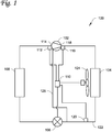
- FIG. 1 shows a compressor system 100 according to an embodiment.
- Compressor system 100 includes compressor 102, condenser 104, expansion device 106 and evaporator 108, fluidly connected to one another.
- Compressor system 100 also includes controller 110.
- Compressor system 100 further includes suction pressure sensor 112 at suction 114 of compressor 102, a discharge pressure sensor 116 at discharge 118 of compressor 102, and a liquid line sensor 120 located along a liquid line 122 between the condenser 104 and expansion device 106 with respect to the flow of working fluid through compressor system 100.
- a cooling line 126 may run from liquid line 122 to compressor 102 and/or other components of compressor system 100.
- Compressor 102 is a compressor that compresses a working fluid of the compressor system 100.
- Compressor 102 may be, for example, a centrifugal compressor, or any other suitable type of compressor.
- Compressor 102 may include a motor.
- the motor of compressor 102 is configured to be cooled by the working fluid of compressor system 100.
- the cooling of the motor of compressor 102 may be affected by a pressure differential within the compressor system 102.
- cooling may be provided by introducing working fluid from liquid line 122 via cooling line 126 into parts of compressor 102. The working fluid introduced into those parts of compressor 102 expands, absorbing heat and cooling the parts of compressor 102, then the working fluid joins other working fluid of compressor system 100, and is compressed by compressor 102.
- Compressor 102 receives the working fluid at suction 114 and compressed working fluid leaves compressor 102 at discharge 118. The compressed working fluid then passes to condenser 104.
- the compressor 102 may have a pressure ratio, determined by the pressure at discharge 118 divided by the pressure at suction 114.
- Condenser 104 includes a heat exchanger. Condenser 104 receives the compressed working fluid from compressor 102, and the working fluid rejects heat via the heat exchanger at condenser 104. The rejection of heat at condenser 104 condenses the working fluid to a liquid. Condenser 104 may be in thermal communication with an ambient environment, and reject heat to that ambient environment.
- One or more blowers 124 may provide airflow over the condenser 104. The one or more blowers may be controlled by controller 110 to provide a variable airflow. In an embodiment, the one or more blowers are operated at a value corresponding to a percentage of the airflow that can be provided by the one or more blowers 124.
- the one or more blowers may affect the heat transfer of the working fluid within condenser 104.
- the heat transfer at condenser 104 affects the pressure at condenser 104 and may influence the suction pressure at suction 114 and the pressure ratio of the compressor. Heat transfer at condenser 104, affected by the operation of the one or more blowers 124, also may affect the liquid line pressure at liquid line 122.
- Liquid line 122 provides fluid connection between condenser 104 and expansion device 106.
- One or more liquid line sensors 120 may be located along liquid line 122.
- the one or more liquid line sensors 120 include a pressure sensor to measure the pressure of the fluid within liquid line 122.
- the pressure sensor may be any suitable pressure sensor for measuring pressure of the fluid within liquid line 122.
- the one or more liquid line sensors 120 further include a temperature sensor.
- Cooling line 126 may provide a fluid connection between liquid line 122 and components of compressor system 100 that are to be cooled. Cooling line 126 may convey some of the working fluid from liquid line 122 to the compressor system 100 components that are to be cooled, such as a motor and/or an inverter of compressor 102. The working fluid from cooling line 126 may be expanded, absorbing heat at the compressor system 100 components being cooled. For the components of compressor 102, the expansion of the working fluid from cooling line 126 may be expansion to the intermediate pressure of the compressor 102.
- Expansion device 106 is a device configured to reduce the pressure of the working fluid. As a result, a portion of the working fluid is converted to a gaseous form. Expansion device 106 may be, for example, an expansion valve, orifice, or other suitable expander to reduce pressure of a refrigerant such as the working fluid. In an embodiment, expansion device 106 includes multiple orifices. In an embodiment, the multiple orifices of expansion device 106 have different sizes. Expansion device 106 may be a controllable expansion device having a variable aperture. In an embodiment, expansion device 106 is an electronic expansion valve. Expansion device 106 may be controlled by controller 110 to adjust its effects on flow and expansion of the working fluid, for example by controlling aperture size of an expansion valve or the number and size of orifices in use based on a signal from controller 110.
- Evaporator 108 receives working fluid from expansion device 106.
- Evaporator 106 includes a heat exchanger where the working fluid can absorb heat, for example absorbing heat from an airflow to be provided to a building to cool the airflow.
- Compressor system 100 may be part of an HVACR system.
- the HVACR system may be, for example, an air-cooled water chiller. This airflow exchanges heat with the working fluid in the evaporator 108, which absorbs heat from the airflow and evaporates the working fluid.
- Controller 110 is a controller which may be operatively coupled to at least suction pressure sensor 112, discharge pressure sensor 116, the one or more liquid line sensors 120, expansion device 106, and the one or more blowers 124. Controller 110 may be operatively coupled to suction pressure sensor 112, discharge pressure sensor 116, and the one or more liquid line sensors 120 such that controller 110 receives pressure readings from each. Controller 110 may further be operatively connected to the one or more liquid line sensors 120 such that controller 120 receives a liquid line temperature. Controller 110 may be operatively coupled to expansion device 106 such that controller 110 can provide commands to expansion device 106. Controller 110 may be operatively connected to the one or more blowers 124 such that it can provide commands to the one or more blowers 124. Controller 110 may include one or more processors and one or more memories.
- Controller 110 may be configured to determine a pressure target based on an intermediate pressure within the compressor 102 and a threshold cooling differential pressure value.
- the pressure target may be a sum of the intermediate pressure in compressor 102 and the threshold cooling differential pressure value.
- the threshold cooling differential pressure value is a value stored in a memory of controller 110.
- Controller 110 may be configured to determine the intermediate pressure in compressor 102. In an embodiment, controller 110 is configured to determine the intermediate pressure based on the suction pressure measured by 112 and the discharge pressure measured by 116. In an embodiment, controller 110 determines the intermediate pressure in compressor 102 by taking a square root of the product of the suction pressure measured by 112 and the discharge pressure measured by 116.
- Controller 110 may be configured to determine a pressure ratio setpoint based on the pressure target and a liquid line pressure measured by the one or more liquid line sensors 120.
- the pressure ratio setpoint may be a desired pressure ratio.
- the pressure ratio may be defined by the discharge pressure of compressor 102 divided by the suction pressure of compressor 102.
- Airflow over condenser 104 may affect the condensation of the working fluid in condenser 104 that is received from discharge 118 of compressor 102 and pressure within condenser 104. The airflow over condenser 104 may thus affect the discharge pressure and pressure ratio of compressor 102.
- the pressure ratio setpoint is determined by comparing the pressure target with the pressure in liquid line 122, measured by the one or more liquid line sensors 120, and when the pressure target exceeds the pressure in liquid line 122, setting the pressure ratio target to the current pressure ratio multiplied by the ratio of the pressure target to the pressure in liquid line 122.
- the pressure ratio setpoint may be maintained at a current level.
- Controller 110 may be configured to control the one or more blowers to operate at a speed determined based on the determined pressure ratio setpoint.
- the control of the blower may be any suitable control loop used to control airflow from the one or more blowers 124 to achieve the determined pressure ratio setpoint.
- the control loop used to control the airflow is a closed-loop control.
- the control loop used to control the airflow includes a proportional-integral-derivative (PID) control loop.
- PID proportional-integral-derivative
- Controller 110 may be configured to determine a subcooling setpoint based on the pressure target and the liquid line pressure in the compressor system.
- the subcooling setpoint is a setpoint that may be used as a control parameter for expansion device 106. Expansion device 106 controls flow out of liquid line 122, and thus the subcooling setpoint and corresponding control of expansion device 106 may affect the differential pressure in compressor system 100.
- controller 110 is configured to determine the subcooling setpoint by determining a liquid pressure difference based on the difference between the pressure target and the actual pressure within liquid line 122 measured by the one or more liquid line sensors 120. The pressure difference may be converted to a temperature offset for subcooling. The temperature offset may then be applied to a current subcooling value to obtain the subcooling setpoint.
- Controller 110 may be configured to control the expansion device 106 based on the subcooling setpoint, for example by adjusting an aperture size within expansion device 106.
- the control of expansion valve 106 may be through any suitable control loop for controlling expansion device 106 based on the subcooling setpoint.
- the control of the expansion device 106 may reference a liquid line temperature measured by the one or more liquid line sensors 120.
- the control loop used to control the expansion device 106 is a closed-loop control.
- the control loop used to control the expansion device 106 includes a PID control loop.
- FIG. 2 shows a flowchart of a method 200 of controlling a compressor system according to an embodiment.
- a pressure target is determined 202.
- a liquid line pressure is received 204.
- a pressure ratio setpoint is determined 206, and a condenser blower is operated based on the pressure ratio setpoint 208.
- a subcooling setpoint is determined 210, and an expansion device is operated based on the subcooling setpoint 212.
- a pressure target is determined 202.
- the pressure target may be a pressure level to maintain cooling of components of one or more compressor system components such as a compressor motor, an inverter, or any other component cooled at least in part using a working fluid of the compressor system.
- the pressure target may be determined based on a pressure differential used to provide cooling to the one or more compressor system components.
- the pressure target may be based on an intermediate pressure within the compressor and a threshold cooling differential pressure value.
- the pressure target is determined by adding a minimum compressor cooling differential pressure value to an intermediate pressure within the compressor.
- the intermediate pressure is determined 218 based on measured suction and discharge pressures.
- the minimum compressor cooling differential pressure value may be a value stored in memory.
- the threshold cooling differential may be determined based on the cooling demand of components of the compressor system. In an embodiment, the threshold cooling differential may be a value calculated based on one or more operational parameters of the compressor. In an embodiment, the threshold cooling differential may be determined based on a mathematical model correlating pressure required for cooling with the one or more operational parameters of the compressor.
- a liquid line pressure is received 204.
- the liquid line pressure may be a value measured by a pressure sensor located along the liquid line, such as the one or more liquid line sensors 120 along liquid line 122 as shown in Figure 1 and described above.
- a pressure ratio setpoint is determined 206.
- the pressure ratio setpoint may be based on the pressure target determined at 202 and the liquid line pressure received at 204.
- the pressure ratio may be defined by the discharge pressure of the compressor of the compressor system divided by the suction pressure of the compressor. Airflow over a condenser of the compressor system may affect the discharge pressure, and thus the pressure ratio.
- the pressure ratio setpoint thus may be used to control airflow over the condenser and the pressure at compressor discharge and the liquid line pressure. In turn, this affects the differential between liquid line pressure and the intermediate pressure and thus the cooling provided to components of the compressor system.
- the pressure ratio setpoint may be determined by comparing the pressure target and the liquid line target and based on that comparison, determining the pressure ratio setpoint, as shown in Figure 3 and described below.
- a condenser blower is operated based on the pressure ratio setpoint 208.
- the operation of the condenser blower based on the pressure ratio setpoint 208 may be accomplished through a control loop for condenser blower airflow including pressure ratio setpoint as a variable.
- a mathematical model correlating pressure ratio setpoint with airflow may be referenced to operate the condenser blower according to the pressure ratio setpoint 208.
- the speed of rotation of the condenser blower is adjusted according to the control loop.
- the control loop used to control the airflow is a closed-loop control.
- the control loop used to control the airflow includes a proportional-integral-derivative (PID) control loop.
- PID proportional-integral-derivative
- a subcooling setpoint is determined 210.
- the subcooling setpoint may be a value for subcooling used in control of an expansion device of the compressor system.
- the expansion device may control flow out of a liquid line of the compressor system, and thus the expansion device may control the liquid line pressure for the compressor system.
- the liquid line pressure may affect whether one or more compressor system components may be cooled by a cooling system, for example when such cooling systems rely on a pressure difference between the liquid line and an intermediate pressure within the compressor.
- the subcooling setpoint may be based on a subcooling value and an offset, the offset computed based on the pressure target determined at 202 and the liquid line pressure received at 204.
- the subcooling setpoint may be determined by determining a liquid pressure difference, determining a subcooling offset, and adding the subcooling offset to a current subcooling value as shown in Figure 4 and described below.
- An expansion device is operated based on the subcooling setpoint 212.
- the operation of the expansion device according to the subcooling setpoint 212 may be accomplished through a control loop including subcooling setpoint as a variable.
- the expansion device may be, for example, expansion device 106 shown in Figure 1 and described above.
- the expansion device may have a controllable aperture size.
- the expansion device is an electronic expansion valve.
- an aperture size of the expansion device is controlled based on the subcooling setpoint 212.
- a mathematical model correlating expansion device position with subcooling setpoint is referenced to operate the expansion device.
- Control based on the subcooling setpoint may reference a current liquid line temperature.
- the liquid line temperature may be measured by a temperature sensor.
- the control loop used to control the expansion device is a closed-loop control.
- the control loop used to control the expansion device includes a PID control loop.
- method 200 may include receiving the suction pressure 214, receiving the discharge pressure 216, and/or determining the intermediate pressure in the compressor 218.
- the suction pressure may be received from a pressure sensor at a suction port of the compressor, such as suction pressure sensor 112 shown in Figure 1 and described above.
- the discharge pressure may be received from a pressure sensor at the discharge port of the compressor, such as discharge pressure sensor 116 shown in Figure 1 and described above.
- the intermediate pressure is determined 218 based on one or more of the suction pressure received at 214 and the discharge pressure received at 216.
- the intermediate pressure is determined 218 by taking the square root of the product of the suction pressure received at 214 and the discharge pressure received at 216.
- the intermediate pressure determined at 218 is used to determine the pressure target 202.
- the method 200 may iterate, for example by returning from operating the condenser blower 208 and operating the expansion device 212 to receiving the suction pressure 214, receiving the discharge pressure 216, or determining the pressure target 202.
- the iteration may be continuous, periodic, or triggered based on conditions such as changes to the operating profile of the compressor system, temperature in components of the compressor system, or ambient environmental conditions.
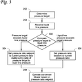
- Figure 3 shows a flowchart of an example method for determining a pressure ratio setpoint according to an embodiment.
- the pressure target determined at 202 and the liquid line pressure received at 204 are compared 302.
- the pressure ratio setpoint is determined based on the current pressure ratio multiplied by a ratio of the pressure target to the liquid line pressure 304.
- the pressure ratio setpoint may be maintained at the current pressure ratio 306.
- the condenser blower may be controlled 208 based on the pressure ratio setpoint 204, as described above.
- Figure 4 shows a flowchart of an example method for determining a subcooling setpoint according to an embodiment. After the target pressure is determined at 202 and the liquid line pressure is received at 204, a liquid pressure difference is determined 402, a subcooling offset is determined 404, and the subcooling offset is added to a current subcooling value 406.
- a liquid pressure difference is determined 402.
- the liquid pressure difference may be a value in units of pressure, for example kPa.
- the liquid pressure difference may be a difference between the target pressure determined at 202 and the liquid line pressure received at 204.
- the liquid pressure difference is determined 402 by subtracting the liquid line pressure received at 204 from the target pressure determined at 202.
- a subcooling offset is determined 404 based on the liquid pressure difference determined at 402.
- the subcooling offset may be a temperature value having units in °F, °C, or K.
- a function is used to convert the liquid pressure difference determined at 402 into a subcooling offset.
- a mathematical model correlating liquid pressure difference and subcooling offset is referenced.
- a lookup table correlating liquid pressure difference and subcooling offset is referenced.
- the subcooling offset determined at 404 is proportional to the liquid pressure difference determined at 402.
- the subcooling offset is added to a current subcooling value 406.
- the subcooling setpoint determined by adding the subcooling offset to the current subcooling value at 406 may then be used to control an expansion device 212 as described above.
Landscapes
- Engineering & Computer Science (AREA)
- Mechanical Engineering (AREA)
- General Engineering & Computer Science (AREA)
- Physics & Mathematics (AREA)
- Thermal Sciences (AREA)
- Control Of Positive-Displacement Air Blowers (AREA)
- Control Of Positive-Displacement Pumps (AREA)
- Air Conditioning Control Device (AREA)
Priority Applications (1)
| Application Number | Priority Date | Filing Date | Title |
|---|---|---|---|
| EP23187681.4A EP4253878A3 (de) | 2019-06-28 | 2020-06-25 | Systeme und verfahren zur steuerung des differentiellen kältemitteldrucks |
Applications Claiming Priority (1)
| Application Number | Priority Date | Filing Date | Title |
|---|---|---|---|
| US16/457,351 US10935293B2 (en) | 2019-06-28 | 2019-06-28 | Systems and methods for controlling differential refrigerant pressure |
Related Child Applications (1)
| Application Number | Title | Priority Date | Filing Date |
|---|---|---|---|
| EP23187681.4A Division EP4253878A3 (de) | 2019-06-28 | 2020-06-25 | Systeme und verfahren zur steuerung des differentiellen kältemitteldrucks |
Publications (2)
| Publication Number | Publication Date |
|---|---|
| EP3757486A1 true EP3757486A1 (de) | 2020-12-30 |
| EP3757486B1 EP3757486B1 (de) | 2023-07-26 |
Family
ID=71170351
Family Applications (2)
| Application Number | Title | Priority Date | Filing Date |
|---|---|---|---|
| EP20182370.5A Active EP3757486B1 (de) | 2019-06-28 | 2020-06-25 | Systeme und verfahren zur steuerung des differentiellen kältemitteldrucks |
| EP23187681.4A Pending EP4253878A3 (de) | 2019-06-28 | 2020-06-25 | Systeme und verfahren zur steuerung des differentiellen kältemitteldrucks |
Family Applications After (1)
| Application Number | Title | Priority Date | Filing Date |
|---|---|---|---|
| EP23187681.4A Pending EP4253878A3 (de) | 2019-06-28 | 2020-06-25 | Systeme und verfahren zur steuerung des differentiellen kältemitteldrucks |
Country Status (3)
| Country | Link |
|---|---|
| US (2) | US10935293B2 (de) |
| EP (2) | EP3757486B1 (de) |
| CN (2) | CN112146309B (de) |
Families Citing this family (3)
| Publication number | Priority date | Publication date | Assignee | Title |
|---|---|---|---|---|
| CN115653932B (zh) * | 2022-10-31 | 2025-11-28 | 珠海格力电器股份有限公司 | 一种轴承供气系统及其方法 |
| US12571568B2 (en) * | 2023-06-09 | 2026-03-10 | Trane International Inc. | Refrigerant circuit expansion valve control |
| CN119042868A (zh) * | 2024-09-30 | 2024-11-29 | 深圳市英维克科技股份有限公司 | 一种制冷系统的压力检测方法、装置、设备及介质 |
Citations (2)
| Publication number | Priority date | Publication date | Assignee | Title |
|---|---|---|---|---|
| JPH01114668A (ja) * | 1987-10-28 | 1989-05-08 | Toshiba Corp | 2段圧縮冷凍サイクル装置 |
| US20180031292A1 (en) * | 2016-07-26 | 2018-02-01 | Mingsheng Liu | Condenser Pressure Control System and Method |
Family Cites Families (12)
| Publication number | Priority date | Publication date | Assignee | Title |
|---|---|---|---|---|
| IT1298522B1 (it) | 1998-01-30 | 2000-01-12 | Rc Condizionatori Spa | Impianto frigorifero con inverter di controllo del compressore raffreddato mediante fluido dell'impianto,e procedimento |
| US7181928B2 (en) | 2004-06-29 | 2007-02-27 | York International Corporation | System and method for cooling a compressor motor |
| US8516850B2 (en) * | 2008-07-14 | 2013-08-27 | Johnson Controls Technology Company | Motor cooling applications |
| US8434323B2 (en) | 2008-07-14 | 2013-05-07 | Johnson Controls Technology Company | Motor cooling applications |
| JP2012072920A (ja) * | 2010-09-27 | 2012-04-12 | Hitachi Appliances Inc | 冷凍装置 |
| US10228168B2 (en) | 2013-03-25 | 2019-03-12 | Carrier Corporation | Compressor bearing cooling |
| WO2017031428A1 (en) * | 2015-08-19 | 2017-02-23 | Gilbert Staffend | High efficiency heating and/or cooling system and methods |
| KR102435203B1 (ko) * | 2015-10-20 | 2022-08-24 | 삼성전자주식회사 | 공기조화기 및 그 제어방법 |
| WO2017133774A1 (en) * | 2016-02-04 | 2017-08-10 | Franke Technology And Trademark Ltd | Refrigeration apparatus with a valve |
| CN108072198B (zh) * | 2016-11-16 | 2020-09-18 | 艾默生环境优化技术(苏州)有限公司 | 压缩机组件及其控制方法和制冷/制热系统 |
| US11448441B2 (en) * | 2017-07-27 | 2022-09-20 | Bergstrom, Inc. | Refrigerant system for cooling electronics |
| CN111417825B (zh) | 2017-10-10 | 2022-07-19 | 江森自控科技公司 | 密封型马达冷却系统 |
-
2019
- 2019-06-28 US US16/457,351 patent/US10935293B2/en active Active
-
2020
- 2020-06-25 EP EP20182370.5A patent/EP3757486B1/de active Active
- 2020-06-25 EP EP23187681.4A patent/EP4253878A3/de active Pending
- 2020-06-28 CN CN202010600695.2A patent/CN112146309B/zh active Active
- 2020-06-28 CN CN202510807416.2A patent/CN120760359A/zh active Pending
-
2021
- 2021-03-01 US US17/188,496 patent/US11604021B2/en active Active
Patent Citations (2)
| Publication number | Priority date | Publication date | Assignee | Title |
|---|---|---|---|---|
| JPH01114668A (ja) * | 1987-10-28 | 1989-05-08 | Toshiba Corp | 2段圧縮冷凍サイクル装置 |
| US20180031292A1 (en) * | 2016-07-26 | 2018-02-01 | Mingsheng Liu | Condenser Pressure Control System and Method |
Also Published As
| Publication number | Publication date |
|---|---|
| US20210180847A1 (en) | 2021-06-17 |
| CN120760359A (zh) | 2025-10-10 |
| US20200408450A1 (en) | 2020-12-31 |
| US10935293B2 (en) | 2021-03-02 |
| EP4253878A3 (de) | 2024-04-03 |
| EP3757486B1 (de) | 2023-07-26 |
| CN112146309B (zh) | 2025-07-08 |
| US11604021B2 (en) | 2023-03-14 |
| CN112146309A (zh) | 2020-12-29 |
| EP4253878A2 (de) | 2023-10-04 |
Similar Documents
| Publication | Publication Date | Title |
|---|---|---|
| US11604021B2 (en) | Systems and methods for controlling differential refrigerant pressure | |
| CN109520136B (zh) | 热泵热水器控制方法和热泵热水器 | |
| US10401068B2 (en) | Air cooled chiller with heat recovery | |
| JP6570746B2 (ja) | 熱媒体循環システム | |
| US10527330B2 (en) | Refrigeration cycle device | |
| EP3267127B1 (de) | Steuerungsvorrichtung und -verfahren für kältekreislaufvorrichtung | |
| EP3365618B1 (de) | Verfahren zur steuerung eines dampfkompressionssystems mit einem variablen empfängerdrucksollwert | |
| CN110691950B (zh) | 空调装置 | |
| JP5240183B2 (ja) | 空気調和装置 | |
| JP6609417B2 (ja) | 空気調和機 | |
| KR101602741B1 (ko) | 항온액 순환 장치 및 그 운전 방법 | |
| JP5229208B2 (ja) | 空気調和装置 | |
| US10941951B2 (en) | Systems and methods for temperature and humidity control | |
| US20110000239A1 (en) | Refrigeration system | |
| EP3460357A1 (de) | Kältemittelkreislaufsystem und verfahren zur steuerung eines kühlmittelkreislaufsystems | |
| EP3411642B9 (de) | Verfahren zur steuerung eines gebläses eines dampfkompressionssystems in übereinstimmung mit einem variablen temperatursollwert | |
| US20220178603A1 (en) | Refrigeration cycle apparatus | |
| EP3353476A1 (de) | System und verfahren zur steuerung eines ölflusses in einem kühlsystem | |
| EP3628942B1 (de) | Verfahren zur steuerung eines dampfkompressionssystems bei reduziertem saugdruck | |
| JP2019052817A (ja) | 空気調和装置 | |
| US11585578B2 (en) | Refrigeration cycle apparatus | |
| GB2561096A (en) | Air conditioner | |
| JP4711852B2 (ja) | 温度調整装置および冷凍サイクル | |
| EP3165846B1 (de) | Kühl- und klimaanlagenvorrichtung | |
| KR20080059911A (ko) | 공기조화기 및 그 제어방법 |
Legal Events
| Date | Code | Title | Description |
|---|---|---|---|
| PUAI | Public reference made under article 153(3) epc to a published international application that has entered the european phase |
Free format text: ORIGINAL CODE: 0009012 |
|
| STAA | Information on the status of an ep patent application or granted ep patent |
Free format text: STATUS: THE APPLICATION HAS BEEN PUBLISHED |
|
| AK | Designated contracting states |
Kind code of ref document: A1 Designated state(s): AL AT BE BG CH CY CZ DE DK EE ES FI FR GB GR HR HU IE IS IT LI LT LU LV MC MK MT NL NO PL PT RO RS SE SI SK SM TR |
|
| AX | Request for extension of the european patent |
Extension state: BA ME |
|
| STAA | Information on the status of an ep patent application or granted ep patent |
Free format text: STATUS: REQUEST FOR EXAMINATION WAS MADE |
|
| 17P | Request for examination filed |
Effective date: 20210628 |
|
| RBV | Designated contracting states (corrected) |
Designated state(s): AL AT BE BG CH CY CZ DE DK EE ES FI FR GB GR HR HU IE IS IT LI LT LU LV MC MK MT NL NO PL PT RO RS SE SI SK SM TR |
|
| GRAP | Despatch of communication of intention to grant a patent |
Free format text: ORIGINAL CODE: EPIDOSNIGR1 |
|
| STAA | Information on the status of an ep patent application or granted ep patent |
Free format text: STATUS: GRANT OF PATENT IS INTENDED |
|
| INTG | Intention to grant announced |
Effective date: 20230118 |
|
| GRAS | Grant fee paid |
Free format text: ORIGINAL CODE: EPIDOSNIGR3 |
|
| P01 | Opt-out of the competence of the unified patent court (upc) registered |
Effective date: 20230511 |
|
| GRAA | (expected) grant |
Free format text: ORIGINAL CODE: 0009210 |
|
| STAA | Information on the status of an ep patent application or granted ep patent |
Free format text: STATUS: THE PATENT HAS BEEN GRANTED |
|
| AK | Designated contracting states |
Kind code of ref document: B1 Designated state(s): AL AT BE BG CH CY CZ DE DK EE ES FI FR GB GR HR HU IE IS IT LI LT LU LV MC MK MT NL NO PL PT RO RS SE SI SK SM TR |
|
| REG | Reference to a national code |
Ref country code: CH Ref legal event code: EP |
|
| REG | Reference to a national code |
Ref country code: IE Ref legal event code: FG4D |
|
| REG | Reference to a national code |
Ref country code: DE Ref legal event code: R096 Ref document number: 602020014326 Country of ref document: DE |
|
| REG | Reference to a national code |
Ref country code: NO Ref legal event code: T2 Effective date: 20230726 |
|
| REG | Reference to a national code |
Ref country code: SE Ref legal event code: TRGR |
|
| REG | Reference to a national code |
Ref country code: LT Ref legal event code: MG9D |
|
| REG | Reference to a national code |
Ref country code: NL Ref legal event code: MP Effective date: 20230726 |
|
| REG | Reference to a national code |
Ref country code: AT Ref legal event code: MK05 Ref document number: 1592341 Country of ref document: AT Kind code of ref document: T Effective date: 20230726 |
|
| PG25 | Lapsed in a contracting state [announced via postgrant information from national office to epo] |
Ref country code: NL Free format text: LAPSE BECAUSE OF FAILURE TO SUBMIT A TRANSLATION OF THE DESCRIPTION OR TO PAY THE FEE WITHIN THE PRESCRIBED TIME-LIMIT Effective date: 20230726 |
|
| PG25 | Lapsed in a contracting state [announced via postgrant information from national office to epo] |
Ref country code: GR Free format text: LAPSE BECAUSE OF FAILURE TO SUBMIT A TRANSLATION OF THE DESCRIPTION OR TO PAY THE FEE WITHIN THE PRESCRIBED TIME-LIMIT Effective date: 20231027 |
|
| PG25 | Lapsed in a contracting state [announced via postgrant information from national office to epo] |
Ref country code: IS Free format text: LAPSE BECAUSE OF FAILURE TO SUBMIT A TRANSLATION OF THE DESCRIPTION OR TO PAY THE FEE WITHIN THE PRESCRIBED TIME-LIMIT Effective date: 20231126 |
|
| PG25 | Lapsed in a contracting state [announced via postgrant information from national office to epo] |
Ref country code: RS Free format text: LAPSE BECAUSE OF FAILURE TO SUBMIT A TRANSLATION OF THE DESCRIPTION OR TO PAY THE FEE WITHIN THE PRESCRIBED TIME-LIMIT Effective date: 20230726 Ref country code: PT Free format text: LAPSE BECAUSE OF FAILURE TO SUBMIT A TRANSLATION OF THE DESCRIPTION OR TO PAY THE FEE WITHIN THE PRESCRIBED TIME-LIMIT Effective date: 20231127 Ref country code: LV Free format text: LAPSE BECAUSE OF FAILURE TO SUBMIT A TRANSLATION OF THE DESCRIPTION OR TO PAY THE FEE WITHIN THE PRESCRIBED TIME-LIMIT Effective date: 20230726 Ref country code: LT Free format text: LAPSE BECAUSE OF FAILURE TO SUBMIT A TRANSLATION OF THE DESCRIPTION OR TO PAY THE FEE WITHIN THE PRESCRIBED TIME-LIMIT Effective date: 20230726 Ref country code: IS Free format text: LAPSE BECAUSE OF FAILURE TO SUBMIT A TRANSLATION OF THE DESCRIPTION OR TO PAY THE FEE WITHIN THE PRESCRIBED TIME-LIMIT Effective date: 20231126 Ref country code: HR Free format text: LAPSE BECAUSE OF FAILURE TO SUBMIT A TRANSLATION OF THE DESCRIPTION OR TO PAY THE FEE WITHIN THE PRESCRIBED TIME-LIMIT Effective date: 20230726 Ref country code: GR Free format text: LAPSE BECAUSE OF FAILURE TO SUBMIT A TRANSLATION OF THE DESCRIPTION OR TO PAY THE FEE WITHIN THE PRESCRIBED TIME-LIMIT Effective date: 20231027 Ref country code: FI Free format text: LAPSE BECAUSE OF FAILURE TO SUBMIT A TRANSLATION OF THE DESCRIPTION OR TO PAY THE FEE WITHIN THE PRESCRIBED TIME-LIMIT Effective date: 20230726 Ref country code: AT Free format text: LAPSE BECAUSE OF FAILURE TO SUBMIT A TRANSLATION OF THE DESCRIPTION OR TO PAY THE FEE WITHIN THE PRESCRIBED TIME-LIMIT Effective date: 20230726 |
|
| PG25 | Lapsed in a contracting state [announced via postgrant information from national office to epo] |
Ref country code: PL Free format text: LAPSE BECAUSE OF FAILURE TO SUBMIT A TRANSLATION OF THE DESCRIPTION OR TO PAY THE FEE WITHIN THE PRESCRIBED TIME-LIMIT Effective date: 20230726 |
|
| PG25 | Lapsed in a contracting state [announced via postgrant information from national office to epo] |
Ref country code: ES Free format text: LAPSE BECAUSE OF FAILURE TO SUBMIT A TRANSLATION OF THE DESCRIPTION OR TO PAY THE FEE WITHIN THE PRESCRIBED TIME-LIMIT Effective date: 20230726 |
|
| REG | Reference to a national code |
Ref country code: DE Ref legal event code: R097 Ref document number: 602020014326 Country of ref document: DE |
|
| PG25 | Lapsed in a contracting state [announced via postgrant information from national office to epo] |
Ref country code: SM Free format text: LAPSE BECAUSE OF FAILURE TO SUBMIT A TRANSLATION OF THE DESCRIPTION OR TO PAY THE FEE WITHIN THE PRESCRIBED TIME-LIMIT Effective date: 20230726 Ref country code: RO Free format text: LAPSE BECAUSE OF FAILURE TO SUBMIT A TRANSLATION OF THE DESCRIPTION OR TO PAY THE FEE WITHIN THE PRESCRIBED TIME-LIMIT Effective date: 20230726 Ref country code: ES Free format text: LAPSE BECAUSE OF FAILURE TO SUBMIT A TRANSLATION OF THE DESCRIPTION OR TO PAY THE FEE WITHIN THE PRESCRIBED TIME-LIMIT Effective date: 20230726 Ref country code: EE Free format text: LAPSE BECAUSE OF FAILURE TO SUBMIT A TRANSLATION OF THE DESCRIPTION OR TO PAY THE FEE WITHIN THE PRESCRIBED TIME-LIMIT Effective date: 20230726 Ref country code: DK Free format text: LAPSE BECAUSE OF FAILURE TO SUBMIT A TRANSLATION OF THE DESCRIPTION OR TO PAY THE FEE WITHIN THE PRESCRIBED TIME-LIMIT Effective date: 20230726 Ref country code: CZ Free format text: LAPSE BECAUSE OF FAILURE TO SUBMIT A TRANSLATION OF THE DESCRIPTION OR TO PAY THE FEE WITHIN THE PRESCRIBED TIME-LIMIT Effective date: 20230726 Ref country code: SK Free format text: LAPSE BECAUSE OF FAILURE TO SUBMIT A TRANSLATION OF THE DESCRIPTION OR TO PAY THE FEE WITHIN THE PRESCRIBED TIME-LIMIT Effective date: 20230726 |
|
| PG25 | Lapsed in a contracting state [announced via postgrant information from national office to epo] |
Ref country code: IT Free format text: LAPSE BECAUSE OF FAILURE TO SUBMIT A TRANSLATION OF THE DESCRIPTION OR TO PAY THE FEE WITHIN THE PRESCRIBED TIME-LIMIT Effective date: 20230726 |
|
| PLBE | No opposition filed within time limit |
Free format text: ORIGINAL CODE: 0009261 |
|
| STAA | Information on the status of an ep patent application or granted ep patent |
Free format text: STATUS: NO OPPOSITION FILED WITHIN TIME LIMIT |
|
| 26N | No opposition filed |
Effective date: 20240429 |
|
| PG25 | Lapsed in a contracting state [announced via postgrant information from national office to epo] |
Ref country code: SI Free format text: LAPSE BECAUSE OF FAILURE TO SUBMIT A TRANSLATION OF THE DESCRIPTION OR TO PAY THE FEE WITHIN THE PRESCRIBED TIME-LIMIT Effective date: 20230726 |
|
| PG25 | Lapsed in a contracting state [announced via postgrant information from national office to epo] |
Ref country code: BG Free format text: LAPSE BECAUSE OF FAILURE TO SUBMIT A TRANSLATION OF THE DESCRIPTION OR TO PAY THE FEE WITHIN THE PRESCRIBED TIME-LIMIT Effective date: 20230726 |
|
| PG25 | Lapsed in a contracting state [announced via postgrant information from national office to epo] |
Ref country code: BG Free format text: LAPSE BECAUSE OF FAILURE TO SUBMIT A TRANSLATION OF THE DESCRIPTION OR TO PAY THE FEE WITHIN THE PRESCRIBED TIME-LIMIT Effective date: 20230726 |
|
| PG25 | Lapsed in a contracting state [announced via postgrant information from national office to epo] |
Ref country code: MC Free format text: LAPSE BECAUSE OF FAILURE TO SUBMIT A TRANSLATION OF THE DESCRIPTION OR TO PAY THE FEE WITHIN THE PRESCRIBED TIME-LIMIT Effective date: 20230726 |
|
| PG25 | Lapsed in a contracting state [announced via postgrant information from national office to epo] |
Ref country code: LU Free format text: LAPSE BECAUSE OF NON-PAYMENT OF DUE FEES Effective date: 20240625 |
|
| PG25 | Lapsed in a contracting state [announced via postgrant information from national office to epo] |
Ref country code: IE Free format text: LAPSE BECAUSE OF NON-PAYMENT OF DUE FEES Effective date: 20240625 |
|
| PG25 | Lapsed in a contracting state [announced via postgrant information from national office to epo] |
Ref country code: BE Free format text: LAPSE BECAUSE OF NON-PAYMENT OF DUE FEES Effective date: 20240630 |
|
| REG | Reference to a national code |
Ref country code: BE Ref legal event code: MM Effective date: 20240630 |
|
| PGFP | Annual fee paid to national office [announced via postgrant information from national office to epo] |
Ref country code: DE Payment date: 20250520 Year of fee payment: 6 |
|
| PGFP | Annual fee paid to national office [announced via postgrant information from national office to epo] |
Ref country code: GB Payment date: 20250520 Year of fee payment: 6 |
|
| PGFP | Annual fee paid to national office [announced via postgrant information from national office to epo] |
Ref country code: NO Payment date: 20250522 Year of fee payment: 6 |
|
| PGFP | Annual fee paid to national office [announced via postgrant information from national office to epo] |
Ref country code: FR Payment date: 20250520 Year of fee payment: 6 |
|
| PGFP | Annual fee paid to national office [announced via postgrant information from national office to epo] |
Ref country code: SE Payment date: 20250520 Year of fee payment: 6 |
|
| PGFP | Annual fee paid to national office [announced via postgrant information from national office to epo] |
Ref country code: CH Payment date: 20250701 Year of fee payment: 6 |
|
| PG25 | Lapsed in a contracting state [announced via postgrant information from national office to epo] |
Ref country code: CY Free format text: LAPSE BECAUSE OF FAILURE TO SUBMIT A TRANSLATION OF THE DESCRIPTION OR TO PAY THE FEE WITHIN THE PRESCRIBED TIME-LIMIT; INVALID AB INITIO Effective date: 20200625 |
|
| PG25 | Lapsed in a contracting state [announced via postgrant information from national office to epo] |
Ref country code: HU Free format text: LAPSE BECAUSE OF FAILURE TO SUBMIT A TRANSLATION OF THE DESCRIPTION OR TO PAY THE FEE WITHIN THE PRESCRIBED TIME-LIMIT; INVALID AB INITIO Effective date: 20200625 |