EP3756913A1 - Hvac-modul - Google Patents
Hvac-modul Download PDFInfo
- Publication number
- EP3756913A1 EP3756913A1 EP19183282.3A EP19183282A EP3756913A1 EP 3756913 A1 EP3756913 A1 EP 3756913A1 EP 19183282 A EP19183282 A EP 19183282A EP 3756913 A1 EP3756913 A1 EP 3756913A1
- Authority
- EP
- European Patent Office
- Prior art keywords
- air
- path
- evaporator
- hvac module
- side path
- Prior art date
- Legal status (The legal status is an assumption and is not a legal conclusion. Google has not performed a legal analysis and makes no representation as to the accuracy of the status listed.)
- Granted
Links
- 238000010438 heat treatment Methods 0.000 claims abstract description 76
- 238000011144 upstream manufacturing Methods 0.000 claims abstract description 25
- 238000001816 cooling Methods 0.000 claims abstract description 6
- 238000007599 discharging Methods 0.000 claims description 3
- 238000005192 partition Methods 0.000 claims description 2
- 230000005484 gravity Effects 0.000 description 10
- 239000012530 fluid Substances 0.000 description 5
- 238000007791 dehumidification Methods 0.000 description 3
- 238000005265 energy consumption Methods 0.000 description 3
- 238000009423 ventilation Methods 0.000 description 3
- 238000004519 manufacturing process Methods 0.000 description 2
- 238000004378 air conditioning Methods 0.000 description 1
- 238000004891 communication Methods 0.000 description 1
- 238000010276 construction Methods 0.000 description 1
- 230000001419 dependent effect Effects 0.000 description 1
- 230000004069 differentiation Effects 0.000 description 1
- 238000001914 filtration Methods 0.000 description 1
- 239000007788 liquid Substances 0.000 description 1
- 230000001105 regulatory effect Effects 0.000 description 1
- 238000000926 separation method Methods 0.000 description 1
Images


Classifications
-
- B—PERFORMING OPERATIONS; TRANSPORTING
- B60—VEHICLES IN GENERAL
- B60H—ARRANGEMENTS OF HEATING, COOLING, VENTILATING OR OTHER AIR-TREATING DEVICES SPECIALLY ADAPTED FOR PASSENGER OR GOODS SPACES OF VEHICLES
- B60H1/00—Heating, cooling or ventilating [HVAC] devices
- B60H1/00642—Control systems or circuits; Control members or indication devices for heating, cooling or ventilating devices
- B60H1/00814—Control systems or circuits characterised by their output, for controlling particular components of the heating, cooling or ventilating installation
- B60H1/00821—Control systems or circuits characterised by their output, for controlling particular components of the heating, cooling or ventilating installation the components being ventilating, air admitting or air distributing devices
- B60H1/00871—Air directing means, e.g. blades in an air outlet
-
- B—PERFORMING OPERATIONS; TRANSPORTING
- B60—VEHICLES IN GENERAL
- B60H—ARRANGEMENTS OF HEATING, COOLING, VENTILATING OR OTHER AIR-TREATING DEVICES SPECIALLY ADAPTED FOR PASSENGER OR GOODS SPACES OF VEHICLES
- B60H1/00—Heating, cooling or ventilating [HVAC] devices
- B60H1/00007—Combined heating, ventilating, or cooling devices
- B60H1/00021—Air flow details of HVAC devices
- B60H1/00064—Air flow details of HVAC devices for sending air streams of different temperatures into the passenger compartment
-
- B—PERFORMING OPERATIONS; TRANSPORTING
- B60—VEHICLES IN GENERAL
- B60H—ARRANGEMENTS OF HEATING, COOLING, VENTILATING OR OTHER AIR-TREATING DEVICES SPECIALLY ADAPTED FOR PASSENGER OR GOODS SPACES OF VEHICLES
- B60H1/00—Heating, cooling or ventilating [HVAC] devices
- B60H1/00007—Combined heating, ventilating, or cooling devices
- B60H1/00021—Air flow details of HVAC devices
-
- B—PERFORMING OPERATIONS; TRANSPORTING
- B60—VEHICLES IN GENERAL
- B60H—ARRANGEMENTS OF HEATING, COOLING, VENTILATING OR OTHER AIR-TREATING DEVICES SPECIALLY ADAPTED FOR PASSENGER OR GOODS SPACES OF VEHICLES
- B60H1/00—Heating, cooling or ventilating [HVAC] devices
- B60H1/00321—Heat exchangers for air-conditioning devices
- B60H1/00328—Heat exchangers for air-conditioning devices of the liquid-air type
-
- B—PERFORMING OPERATIONS; TRANSPORTING
- B60—VEHICLES IN GENERAL
- B60H—ARRANGEMENTS OF HEATING, COOLING, VENTILATING OR OTHER AIR-TREATING DEVICES SPECIALLY ADAPTED FOR PASSENGER OR GOODS SPACES OF VEHICLES
- B60H1/00—Heating, cooling or ventilating [HVAC] devices
- B60H1/00485—Valves for air-conditioning devices, e.g. thermostatic valves
-
- B—PERFORMING OPERATIONS; TRANSPORTING
- B60—VEHICLES IN GENERAL
- B60H—ARRANGEMENTS OF HEATING, COOLING, VENTILATING OR OTHER AIR-TREATING DEVICES SPECIALLY ADAPTED FOR PASSENGER OR GOODS SPACES OF VEHICLES
- B60H1/00—Heating, cooling or ventilating [HVAC] devices
- B60H1/00507—Details, e.g. mounting arrangements, desaeration devices
- B60H1/00514—Details of air conditioning housings
- B60H1/00542—Modular assemblies
-
- B—PERFORMING OPERATIONS; TRANSPORTING
- B60—VEHICLES IN GENERAL
- B60H—ARRANGEMENTS OF HEATING, COOLING, VENTILATING OR OTHER AIR-TREATING DEVICES SPECIALLY ADAPTED FOR PASSENGER OR GOODS SPACES OF VEHICLES
- B60H1/00—Heating, cooling or ventilating [HVAC] devices
- B60H1/00642—Control systems or circuits; Control members or indication devices for heating, cooling or ventilating devices
- B60H1/00814—Control systems or circuits characterised by their output, for controlling particular components of the heating, cooling or ventilating installation
- B60H1/00878—Control systems or circuits characterised by their output, for controlling particular components of the heating, cooling or ventilating installation the components being temperature regulating devices
-
- B—PERFORMING OPERATIONS; TRANSPORTING
- B60—VEHICLES IN GENERAL
- B60H—ARRANGEMENTS OF HEATING, COOLING, VENTILATING OR OTHER AIR-TREATING DEVICES SPECIALLY ADAPTED FOR PASSENGER OR GOODS SPACES OF VEHICLES
- B60H1/00—Heating, cooling or ventilating [HVAC] devices
- B60H1/00007—Combined heating, ventilating, or cooling devices
- B60H1/00021—Air flow details of HVAC devices
- B60H2001/00078—Assembling, manufacturing or layout details
- B60H2001/00092—Assembling, manufacturing or layout details of air deflecting or air directing means inside the device
-
- B—PERFORMING OPERATIONS; TRANSPORTING
- B60—VEHICLES IN GENERAL
- B60H—ARRANGEMENTS OF HEATING, COOLING, VENTILATING OR OTHER AIR-TREATING DEVICES SPECIALLY ADAPTED FOR PASSENGER OR GOODS SPACES OF VEHICLES
- B60H1/00—Heating, cooling or ventilating [HVAC] devices
- B60H1/00007—Combined heating, ventilating, or cooling devices
- B60H1/00021—Air flow details of HVAC devices
- B60H2001/00114—Heating or cooling details
- B60H2001/00128—Electric heaters
-
- B—PERFORMING OPERATIONS; TRANSPORTING
- B60—VEHICLES IN GENERAL
- B60H—ARRANGEMENTS OF HEATING, COOLING, VENTILATING OR OTHER AIR-TREATING DEVICES SPECIALLY ADAPTED FOR PASSENGER OR GOODS SPACES OF VEHICLES
- B60H1/00—Heating, cooling or ventilating [HVAC] devices
- B60H1/00007—Combined heating, ventilating, or cooling devices
- B60H1/00021—Air flow details of HVAC devices
- B60H2001/0015—Temperature regulation
- B60H2001/00164—Temperature regulation with more than one by-pass
Landscapes
- Physics & Mathematics (AREA)
- Thermal Sciences (AREA)
- Engineering & Computer Science (AREA)
- Mechanical Engineering (AREA)
- Air-Conditioning For Vehicles (AREA)
Abstract
Description
- The present invention concerns a HVAC module, in particular for an automotive vehicle. The invention also concerns a motor vehicle equipped with such a HVAC module.
- So-called HVAC modules ("Heating-Ventilation-Air Conditioning Module") are often used to create pleasant air conditions for passengers in the passenger compartment of a motor vehicle. Such HVAC modules usually have an evaporator for dehumidifying and cooling the air, a heating device for heating the air and several air outlets which are fluidically connected to several ventilation openings limiting the vehicle interior. The ventilation openings shall be adjacent to different compartments of the vehicle interior, such as a foot compartment, a compartment in the area of a window pane, or an area along a central axis of the vehicle interior.
- It is important to supply air outlets of the HVAC module with air that is adapted to the needs of the vehicle occupants in terms of temperature, humidity and air volume.
- It is therefore a task of the present invention to create an improved or at least alternative HVAC module, which allows the simultaneous generation of air with spatially varying air temperature and humidity, which can be individually supplied to different areas of a vehicle interior.
- This task is solved by the subject of independent claims. Advantageous embodiments are the subject of the dependent claims.
- The basic idea of the invention is therefore to divide an air path of a HVAC module with an evaporator and a heating device into a main path leading through the evaporator and the heating device and into a side path leading past the evaporator and the heating device and, in addition, to control, by means of a first and a second valve flap, the sectional flow of the air through the main and side path in such a way that different air outlets of the HVAC module can be supplied with a different throughput of air and/or with air of different temperature and/or humidity.
- In this way, when the HVAC module is installed, different areas of the vehicle interior of a motor vehicle can be supplied with individually adjustable quantities of air - adapted to the individual needs and wishes of the occupants - while at the same time both temperature and humidty of the air can also be individually adjusted. This means that individually adapted ventilation conditions can be achieved for different parts of the vehicle interior, which are pleasant for the individual occupants.
- A HVAC module in accordance with the invention, in particular for a motor vehicle, comprises an air path for the passage of air, in which an evaporator for cooling and dehumidifying the air and a heating device for heating the air are arranged. The evaporator and the heating device divide the air path into a main path, which passes through the evaporator and the heating device, and a side path, which runs fluidically parallel to the main path and passes the evaporator and the heating device. The side path branches off from the main path upstream of the evaporator, flows back into the main path downstream of the heating device and is also fluidically connected to the main path between the evaporator and the heating device. The HVAC module also includes a first side path portion of the side path passing the evaporator and a second side path portion of the side path passing the heater. In addition, the HVAC module has a first valve flap arranged in the air path and adjustable between a closed position and an open position such that in the closed position no air upstream of the evaporator can flow from the main path directly into the first side path portion and in the open position air upstream of the evaporator can flow from the main path directly into the first side path portion. The HVAC module also has a second valve flap arranged in the air path and adjustable between a first, second and third position such that in the first position air can flow from the first side path portion directly into a main path intermediate portion formed between the evaporator and the heater, but no air can flow from the first side path portion and from the main path intermediate portion directly into the second side path portion. In the second position, air can flow from the main path intermediate portion directly into the second side path portion, but no air can flow from the first side path portion directly into the main path intermediate portion and directly into the second side path portion. In the third position, air can flow from both the first side path portion and the main intermediate path portion directly into the second side path portion. In this way, by means of only two valve flaps, a large number of flow paths can be set for the flow paths through the main and side path, so that in portions of the side path and the main path a different amount of air and also air of different temperature or humidity can flow in each case.
- According to a preferred embodiment, the second valve flap is arranged in the air path and adjustable between the second and third positions such that in the second position the flow cross-section for air that can be led from the intermediate main path portion directly into the second side path portion is larger than in the third position. With this embodiment, the amount of air flowing from the first side path portion and from the main path intermediate portion to the second side path portion can be variably adjusted.
- The HVAC module advantageously comprises control means arranged to adjust the first valve flap between the closed position and the open position and to adjust the second valve flap between the first, second and third positions and, in use, to control the first valve flap and the second valve flap. This allows the control of both valve flaps for easy setting of different operating states of the HVAC module.
- According to another preferred embodiment, the HVAC module has a first operating condition in which the first valve flap is in the closed position and the second valve flap is in the first position so that air can flow upstream of the evaporator from the main path through the evaporator but not directly into the first side path portion, and air can flow from the main path intermediate portion through the heater, but not directly into the second side path portion. This embodiment enables particularly strong dehumidification and heating of the air supplied to the HVAC module and is particularly advantageous for humid and cold air supplied to the HVAC module.
- According to another preferred embodiment, the HVAC module has a second operating condition in which the first valve flap is in the open position and the second valve flap is in the first position so that air can flow upstream of the evaporator from the main path through the evaporator and directly into the first side path portion, and air can flow from the main path intermediate portion through the heater, but not directly into the second side path portion. This type of embodiment enables particularly strong heating of the air supplied to the HVAC module and is particularly advantageous for dry and very cold air supplied to the HVAC module. At the same time the evaporator can be operated with reduced capacity or switched off so that the energy consumption of the HVAC module is reduced.
- According to another preferred embodiment, the HVAC module has a third operating state in which the first valve flap is in the closed position and the second valve flap is in the second position so that air can flow upstream from the evaporator from the main path through the evaporator, but not directly into the first side path portion, and air can flow from the main path intermediate portion through the heater and directly into the second side path portion. This embodiment enables particularly strong dehumidification and cooling of the air supplied to the HVAC module and is particularly advantageous when the air supplied to the HVAC module is particularly warm and/or humid. In addition, this version allows the heater to be operated at reduced power or to be switched off so that the energy consumption of the HVAC module can be reduced.
- According to another preferred embodiment, the HVAC module has a fourth operating condition in which the first valve flap is in the open position and the second valve flap is in the third position so that air can flow upstream of the evaporator from the main path through the evaporator and directly into the first side path portion, and air can flow from the main path intermediate portion through the heater and directly into the second side path portion. This embodiment allows a strong heating of the air supplied to the HVAC module and is particularly advantageous when the air supplied to the HVAC module is particularly dry and cold. In addition, with this embodiment the evaporator can be operated with reduced output or switched off. The same applies, alternatively or additionally, to a blower for feeding air into the HVAC module. In other words, the HVAC-module can be operated at maximum throughput of air and lowest electrical consumption.
- According to another preferred embodiment, the HVAC module has a fifth operating state in which the first valve flap is in the closed position and the second valve flap is in the third position so that air can flow upstream from the evaporator from the main path through the evaporator but not directly into the first side path portion, and air can flow from the main path intermediate portion through the heater and directly into the second side path portion. This embodiment enables particularly strong dehumidification and heating of the air supplied to the HVAC module and is particularly advantageous for humid and cold air supplied to the HVAC module. In addition, with this version, the heater can be operated at reduced power or switched off so that the energy consumption of the HVAC module can be reduced.
- The air path is preferably formed exclusively by the main path and the side path. This embodiment enables a particularly compact geometry of the HVAC module and, in addition, a particularly efficient flow through the air path.
- Prefebably, the air path is divided into the main path and the side path without dividing walls. This embodiment also enables a particularly efficient air flow through the air path and additionally reduces the manufacturing costs of the HVAC module.
- In accordance with another advantageous embodiment, the main path and the side path are bounded by a common housing. This embodiment also enables a particularly compact geometry of the HVAC module and, in addition, a particularly efficient flow through the air path.
- According to another advantageous embodiment, the main path and the side path do not cross. This embodiment also enables a particularly compact geometry of the HVAC module and, in addition, a particularly efficient air flow through the air path.
- According to another advantageous embodiment, the first side path portion and the second side path portion pass the evaporator and the heating device respectively on the same side of the main path. This embodiment also enables a particularly compact geometry of the HVAC module and, in addition, a particularly efficient flow through the air path. In addition, air outlets arranged in an extension of the side path can be flowed through in this way with a larger quantity of air than air outlets arranged in an extension of the main path.
- The heating device preferably comprises a plurality of heating portions, the heating device being configured in such a way that the individual heating portions can be heated individually. In this way, air outlets downstream of the heating portions of the heating device can be supplied with air of different heated air intensity and thus with air of different air temperature - and supplied via these different zones of the vehicle interior.
- In another preferred embodiment, the HVAC module includes an air outlet assembly arranged in the air path with a plurality of air outlets for removing air from the HVAC module, the air outlets being adjacent to each other. This embodiment enables a particularly compact geometry of the HVAC module. In addition, a particularly simple and cost-effective production of the HVAC module is achieved in this way.
- According to another preferred embodiment, the majority of air outlets are arranged in a grid pattern in at least two grid rows and in at least two grid columns. This embodiment requires very little construction space. It is also possible to supply the individual air outlets with air at different temperature/humidity and/or with different air flow rates.
- According to another preferred embodiment, the air outlets of each grid line have a common adjustable air flap for closing the outlet openings of the air outlets of the grid line in question. The respective air damper can be adjusted between a closed state, in which no air can flow through the respective outlet openings, and an open state with maximum opening. It goes without saying that a large number of intermediate positions between the closed position and the open position can also be set in the air damper. In this way, the air mass flow, which exits the module via the air outlets assigned to the respective air flap and is fed to a vehicle interior fluidly connected downstream of the module, can be flexibly adjusted and thus also varied.
- In accordance with a particularly advantageous embodiment, the air flaps of a respective grid line extend along a direction, preferably the vertical direction, orthogonal to a direction, preferably the transverse direction, along which the heating portions of the heating device are arranged side by side.
- In this way, air can flow through air outlets fluidically connected downstream of the heating portions of the heating device, the quantity and temperature of which can be individually controlled or regulated for air outlets in different grid lines and different grid columns, in a particularly large number of combinations and also with particular precision.
- In accordance with a preferred embodiment, the air outlets are arranged in at least one, preferably exactly one, grid line in an extension of the side path. This means that air outlets arranged in an extension of the side path can be flowed through with a particularly high quantity of air.
- According to another preferred embodiment, the air outlets are arranged in at least one, preferably exactly two, grid lines in an extension of the main path. With this embodiment, air outlets arranged in the extension of the main path can thus be flowed through with an air of particularly high temperature.
- According to another preferred embodiment, the air outlets are arranged in at least one, preferably exactly one, grid line, both in a lengthening of the side path and in an extension of the main path. In this way, air outlets arranged in an extension of the main path and the side path can be flowed through with air at particularly high temperatures and in particularly large quantities.
- The invention also concerns an automotive motor vehicle with a vehicle interior and with at least one fresh air path which, in order to supply the vehicle interior with fresh air, fluidically connects the vehicle interior with an external environment of the motor vehicle. The motor vehicle also comprises a HVAC module, as invented, arranged in at least one fresh air path. Advantages of the HVAC module according to the invention are thus also transferred to the motor vehicle according to the invention.
- When the HVAC module is installed in the vehicle, it is advantageous that the heating device is arranged in the air path in such a way that no air can flow past it in the direction of gravity below the heating device.
- A particular advantage of the HVAC module when installed in a motor vehicle is that the evaporator is arranged in the air path in such a way that no air can flow past the evaporator in the direction of gravity below it.
- In this way, a particularly robust and efficient design of the HVAC module can be achieved, especially for collecting and discharging condensate condensed in the area of the evaporator.
- Further important features and advantages of the invention result from the claims, the drawings and the accompanying figure description on the basis of the drawings.
- It goes without saying that the features mentioned above and the features to be explained below may not only be used in the combination indicated, but also in other combinations or in a unique position, without leaving the scope of this invention.
- Preferred examples of the execution of the invention are shown in the drawings and are explained in more detail in the following description, whereby identical reference signs refer to identical or similar or functionally identical components.
- They show, each schematically:
- Fig. 1
- a simplified representation of a HVAC module in a sectional view,
- Fig. 2
- a simplified representation of a HVAC module with connected fan compartment in a sectional view perpendicular to the view of
Figure 1 , - Fig. 3
- a detailed view of an outlet arrangement of the HVAC module,
- Fig. 4
- a detailed view of the HVAC module in a first operating state,
- Fig. 5
- a detailed view of the HVAC module in a second operating state,
- Fig. 6
- a detailed view of the HVAC module in a third operating state,
- Fig. 7
- shows a detailed view of the HVAC module in a fourth operating state,
- Fig. 8
- a detailed view of the HVAC module in a fifth operating state.
-
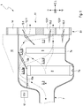
Figure 1 shows an example of aHVAC module 1 without aconnected blower room 24 in a sectional view along a principal extension direction E - hereinafter also referred to as longitudinal direction L - of an air path 2 and along a vertical direction H which extends perpendicularly to the longitudinal direction L or principal extension direction E of air path 2. A transverse direction Q extends perpendicularly to both the vertical direction H and the longitudinal direction L. - The
HVAC module 1 comprises anair path housing 7 which limits an air path 2 for the passage of air supplied to theHVAC module 1. Air path 2 contains anevaporator 8 for cooling and dehumidifying the air and aheating device 9 downstream of theevaporator 8 for heating the air. Theevaporator 8 and theheating device 9 divide the air path 2 into a main path 3, which leads through theevaporator 8 and theheating device 9, and a side path 4, which runs fluidically parallel to the main path 3 and leads past theevaporator 8 and theheating device 9. In the context of this invention, fluidic parallel fluid paths are not geometrically parallel fluid paths, but fluid paths which are connected to each other at a branch point and at an orifice point, whereby the fluid paths can also be connected to each other between the branch point and the orifice point. Fluidically parallel fluid paths, however, can also be geometrically parallel to each other or not geometrically parallel to each other. - The side path 4 branches off from the main path 3 upstream of the
evaporator 8 and flows back into the main path 3 downstream of theheating device 9. Between theevaporator 8 and theheating device 9, the side path 4 is fluidically connected to an intermediate main path portion 6 of the main path 3 arranged between theevaporator 8 and theheating device 9. A first side path portion 5a of side path 4 passes theevaporator 8. A second side path portion 5b of the side path 4 leads past theheating device 9. - In the examples of
figures 1 and2 , air path 2 is exclusively formed by the main path 3 and the side path 4. As shown, air path 2 can be divided into main path 3 and side path 4 without a partition wall. Infigures 4 to 8 , separation of the air path 2 into the main path 3 and the side path 4 is indicated by a virtual dividing line T. - The air path 2 is divided into the main path 3 and the side path 4 by a virtual dividing line T. The air path 2 is divided into the main path 3 and the side path 4 by a virtual dividing line T.
- In
figures 1 and2 it can also be seen that the main path 3 and the side path 4 are bounded by acommon housing 7. The main path 3 and the side path 4 are designed in such a way that they do not cross each other. The first side path portion 5a and the second side path portion 5b lead past theevaporator 8 and theheating device 9 respectively on the same side of the main path 3 inFigure 1 . - As shown in
Figure 1 ,module 1 comprises afirst valve flap 10a and asecond valve flap 10b. Thefirst valve flap 10a is located in the air path 2 and is adjustable between a closed position and an open position, such that in the closed position no air can flow upstream of theevaporator 8 from the main path 3 directly into the first side path portion 5a. In the open position, on the other hand, air can flow upstream ofevaporator 8 from main path 3 directly into the first side path portion 5a. - In the context of this invention, a direct flow is understood to mean a flow in which the air does not flow through the
evaporator 8 or through theheating device 9. Thesecond valve flap 10b is arranged in the air path 2 and adjustable between a first, second and third position, so that in the first position air can flow from the first side path portion 5a directly into the main path intermediate portion 6. However, in the first position of thesecond valve flap 10b no air can flow from the first side path portion 5a and from the main path portion 6 directly into the second side path portion 5b. In the second position of thesecond valve flap 10b, air from the main path intermediate portion 6 can flow directly into the second side path portion 5b, but no air from the first side path portion 5a can flow directly into the main path intermediate portion 6 and directly into the second side path portion 5b. In the third position of thesecond valve flap 10b, air can flow directly from both the first side path portion 5a and the main-path intermediate portion 6 to the second side path portion 5b. - As an example,
Figure 1 shows thefirst valve flap 10a in the closing position and thesecond valve flap 10b in the first position.Figure 1 shows afirst valve flap 10a in the furnace position with dotted lines and asecond valve flap 10b in the second position. Thesecond valve flap 10b in the example inFigure 1 is arranged in air path 2 and is adjustable between the second and the third position in such a way that in the second position a flow cross-section for air that can be guided directly from the intermediate main path portion 6 to the second side path portion 5b is larger than in the third position. In other words, in the second position of thesecond valve flap 10b more air can flow from the main path intermediate portion 6 directly into the second side path portion 5b than in the third position. - In
Figure 1 it can be seen that themodule 1 comprises acontrol device 17 which is set up for adjusting thefirst valve flap 10a between the closed position and the open position and for adjusting thesecond valve flap 10b between the first, second and third position (the communication of thecontrol device 17 with the first and second valve flaps 10a and 10b is not shown inFigure 1 for reasons of clarity). WhenHVAC module 1 1 is in operation, thecontrol unit 17 controls the first and second valve flaps 10a, 10b to adjust the first and second valve flaps 10a, 10b, respectively. In the example scenario of the figures, the first and second valve flaps 10a, 10b can be controlled independently of each other by thecontrol system 17 and can therefore be adjusted independently of each other. - By adjusting the two
valve flaps HVAC module 1.Figures 4 to 8 each illustrate a first to fifth operating state ofmodule 1. -
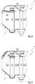
Figure 4 shows a first operating state ofHVAC module 1 in which thefirst valve flap 10a is in the closed position and thesecond valve flap 10b is in the first position. In this operating condition, air can flow upstream from theevaporator 8 from the main path 3 through theevaporator 8, but not directly into the first side path portion 5a, and air can flow from the main path portion 6 through theheater 9, but not directly into the second side path portion 5b. -
Figure 5 shows a second operating state ofHVAC module 1 in which thefirst valve flap 10a is in the open position and thesecond valve flap 10b is in the first position. In this second operating condition, air can flow upstream from theevaporator 8 from the main path 3 through theevaporator 8 and directly into the first side path portion 5a, and air can flow from the main path portion 6 through theheater 9, but not directly into the second side path portion 5b. -
Figure 6 shows a third operating state ofHVAC module 1 in which thefirst valve flap 10a is in the closed position and thesecond valve flap 10b is in the second position. In this third operating condition, air can flow upstream from theevaporator 8 from the main path 3 through theevaporator 8, but not directly into the first side path portion 5a, and air can flow from the main path portion 6 through theheater 9, and directly into the second side path portion 5b. -
Figure 7 shows a fourth operating state ofHVAC module 1 in which thefirst valve flap 10a is in the open position and thesecond valve flap 10b is in the third position. In this fourth operating condition, air can flow upstream from theevaporator 8 from the main path 3 through theevaporator 8 and directly into the first side path portion 5a, and air can flow from the main path portion 6 through theheater 9 and directly into the second side path portion 5b. -
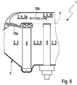
Figure 8 shows a fifth operating state of the HVAC module in which thefirst valve flap 10a is in the closed position and thesecond valve flap 10b is in the third position. In this fifth operating condition, air can flow upstream from theevaporator 8 from the main path 3 through theevaporator 8, but not directly into the first side path portion 5a, and air can flow from the main path portion 6 through theheater 9 and directly into the second side path portion 5b. - In the third operating condition, the flow cross-section for air that can be led from the intermediate main path portion 6 directly into the second side path portion 5b and via the first side path portion 5a is greater than in the fourth and fifth operating condition.
- In the following, reference is made to
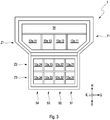
Figure 3 , which shows anair outlet arrangement 11 of theHVAC module 1 in a plan view along the main extension direction E and along the longitudinal direction L, respectively.Module 1 therefore comprises anair outlet assembly 11 arranged in air path 2 with a plurality of air outlets 12 for discharging air frommodule 1, the air outlets 12 being arranged adjacent to each other. The air outlets 12 are arranged in a grid pattern in several grid rows Z and grid columns S. The example inFigure 3 shows three grid lines Z1, Z2, Z3 and four grid columns S1, S2, S3, S4. This means that a total of twelve air outlets 12 are provided in the example. Each individual air outlet 12 is thus assigned both to a specific grid line Z1, Z2, Z3 and to a specific grid column S1, S2, S3, S4. In the following, the nomenclature 12.ZS is used to designate which grid line Z and which grid column S a respective air outlet 12 is assigned to. The air diffuser 12.34 is thus assigned to the third grid line Z3 and the fourth grid column S4. -
Figure 3 also shows that each air outlet 12 includes an outlet opening 12a. The same nomenclature is used for outlet openings 12a as for air outlets 12, i.e. the outlet opening 12a.34 is assigned to the third grid line Z3 and the fourth grid column S4. Theair outlet assembly 11 may include an outlet plate in which the outlet openings 12a are arranged. - Air from the
HVAC module 1 can be directed into different areas of the vehicle interior of a motor vehicle via the different outlet openings 12a. For this purpose, the respective outlet openings 12a can be fluidically connected to different zones of the vehicle interior via suitable air ducts (not shown). It is conceivable, for example, that the outlet opening 12a.11 is fluidically connected via a suitable air duct to the area of a windscreen of the motor vehicle. It is also conceivable, for example, that the outlet opening 12a.31 is fluidically connected to the area of a rear footwell of the vehicle interior via a suitable air duct. - In the example of
Figure 1 , the air outlets 12 of each of the three grid lines Z1 to Z3 can be closed with a common air flap 13.1, 13.2, 13.3. In other words, each of the grid lines Z1 to Z3 is assigned an air flap 13.1, 13.2, 13.3. In this way, the air outlets 12 of the air outlet arrangement can be flowed through with a variable and different amount of air. -
Figure 2 shows an alternative scenario in which each air outlet is assigned an individual air flap to close the respective air outlet openings. In the example ofFigure 2 the four shown air outlets 12.11, 12.12, 12.13, 12.14 of the grid line Z1 shown can be closed with their own air flaps 13.11, 13.12, 13.13 or 13.14. This allows a more individual control of the individual air outlets compared to the example inFigure 1 . On the other hand, the variant offigure 1 is technically simpler and therefore cheaper than the variant offigure 2 . - In the example of
Figure 1 , theair outlet arrangement 11 has exactly one grid line Z1 whose air outlets 12 are arranged in an extension of the side path 4. The air outlets 12 of grid line Z1 are additionally arranged in an extension of main path 3. In the example ofFigure 1 , theair outlet arrangement 11 also has two grid lines Z2, Z3, whose air outlets 12 are arranged in an extension of the main path 3. The extensions of the side path 4 and of the main path 3 extend in the case of the figures along the main extension direction E or the longitudinal direction L. It is also conceivable, however, that an extension of the side path 4 or of the main path 3 is designed as a fluidically downstream extension which is not geometrically linear and follows the side path 4 or the main path 3. Arrows and dashed lines are used to illustrate possible air flow paths. - In an installed condition of the
HVAC module 1 in a motor vehicle, theheating device 9 is appropriately arranged in the air path 2, as indicated, such that no air can flow past theheating device 9 in the direction of gravity G below it. Such a scenario, in which the vertical direction H is opposite to gravity direction G, is shown inFigure 1 . When themodule 1 is installed in the motor vehicle, theheating device 9 can touch alower housing wall 7a of thehousing 7 with respect to the direction of gravity G as shown inFigure 1 . When themodule 1 is installed in the motor vehicle, theheating device 9 is conveniently located below the bypass path 4 with respect to the direction of gravity G. Themodule 1 can also be installed in the motor vehicle with theheating device 9 in the direction of gravity G below the side path 4. In the installed state, theevaporator 8 can also be arranged in air path 2 in such a way that no air in gravity direction G can flow past theevaporator 8 below it, which is also illustrated directly inFigure 1 . When theHVAC module 1 is installed in vehicle, theevaporator 8 can touch alower housing wall 7a of thehousing 7 with respect to the direction of gravity G as shown inFigure 1 . At the lower end of theevaporator 8, in relation to gravity direction G, a condensate path can again be formed for the discharge of liquid condensed in the air path or on theevaporator 8 from HVAC module 1 (the condensate path is not shown in the figures for the sake of clarity). -
Figure 2 shows aHVAC module 1 with aconnected blower room 24 in a sectional view along the main extension direction E and perpendicular to the vertical direction H or perpendicular to the transverse direction Q. Theblower room 24 is limited by ablower housing 23 and is fluidically connected to air path 2 and via anair inlet 16 to areturn path 15. In theblower room 24 there is afilter 27 for filtering air and ablower 25 for conveying air from theblower room 24 into the air path 2 and for sucking air through theair intake 16. Aelectrical motor 26 is connected to theblower 25 to operate theblower 25. Thefeedback path inlet 14 is fluidically connected to the dashedfeedback path 15. - As can also be seen from
Figure 2 , theheater 9 comprises a plurality of heating portions 9a in which air flowing through theheater 9 can be heated. For this purpose, electrical heating elements (not shown) may be arranged in the respective heating portion 9a, which heat the air flowing through the respective heating portion 9a. In the example inFigure 2 , five heating portions 9a are arranged next to each other along the transverse direction Q and at a distance from each other. The five heating portions 9a are additionally marked inFigure 2 with the reference sign 9a.1 to 9a.5 for better differentiation. The five heating portions 9a allow the air guided through the various heating portions 9a to be heated to different degrees, i.e. individually, by setting the electrical heating elements individually for each heating portion 9a. This in turn allows air to be supplied at different temperatures to the various air outlets 12 of theair outlet arrangement 11, which are connected fluidically downstream of theheating device 9. - As
Figure 2 shows, the air outlet 12.11 is presumably primarily traversed by air from heating portion 9a.1. On the other hand, the air diffuser 12.14 is primarily supplied with air from heating portion 9a.5, etc. The configuration of theheating device 9 with the heating portions 9a and theair outlet arrangement 11 with the air outlets 12 presented here thus makes it possible to introduce heated air of varying intensity via the air outlets 12 into different areas of a vehicle interior fluidically following the air outlet arrangement 12 of themodule 1.
Claims (15)
- HVAC module (1), in particular for a motor vehicle,- with an air path (2) for air to flow through, in which an evaporator (8) for cooling and dehumidifying the air and a heating device (9) for heating the air are arranged, which subdivide the air path (2) into a main path (3), which passes through the evaporator (8) and the heating device (9), and into a side path (4) which runs fluidically parallel to the main path (3) and passes the evaporator (8) and the heating device (9),- wherein the side path (4) branches off from the main path (3) upstream of the evaporator (8) and opens into the main path again downstream of the heating device (9) and is fluidically connected to the main path (3) between the evaporator (8) and the heating device (9),- wherein the side path (4) comprises a first side path portion (5a) passing the evaporator (8) and a second side path portion (5b) passing the heater (9),- having a first valve flap (10a) which is arranged in the air path (2) and is adjustable between a closed position and an open position in such a way that:- in the closed position, no air can flow upstream of the evaporator (8) from the main path (3) directly into the first side path portion (5a),- in the open position, air can flow upstream of the evaporator (8) from the main path (3) directly into the first side path portion (5a),- having a second valve flap (10b) which is arranged in the air path (2) and is adjustable between a first, second and third position such that:- in the first position, air can flow directly from the first side path portion (5a) into a main-path intermediate portion (6) formed between the evaporator (8) and the heater (9), but no air can flow directly from the first side path portion (5a) and from the main-path intermediate portion (6) into the second side path portion (5b),- in the second position, air can flow from the main path intermediate portion (6) directly into the second side path portion (5b), but no air can flow from the first side path portion (5a) directly into the main path intermediate portion (6) and directly into the second side path portion (5b),- in the third position, air can flow directly from both the first side path portion (5a) and the main path intermediate portion (6) into the second side path portion (5b).
- HVAC module according to claim 1,
characterized in that
the second valve flap (10b) is arranged in the air path (2) and is adjustable between the second and third positions such that in the second position the flow cross-section for air which can be guided directly from the intermediate main path portion (6) into the second side path portion (5b) is greater than in the third position. - HVAC module according to claim 1 or 2,
characterized in that
the HVAC module comprises a control means (11) which is arranged to adjust the first valve flap (10a) between the closed position and the open position and to adjust the second valve flap (10b) between the first, second and third positions and in operation controls the first valve flap (10a) and the second valve flap (10b). - HVAC module according to claim 1 to 3,
characterized in that
the HVAC module (1) has a (first) operating condition in which the first valve flap (10a) is in the closed position and the second valve flap (10b) is in the first position such that:- air can flow upstream of the evaporator (8) from the main path (3) through the evaporator (8) but not directly into the first side path portion (5a); and- air can flow from the main path intermediate portion (6) through the heater (9) but not directly into the second side path portion (5b). - HVAC module according to one of the previous claims,
characterized in that
the HVAC module (1) has a (second) operating condition in which the first valve flap (10a) is in the open position and the second valve flap (10b) is in the first position such that:- air can flow upstream of the evaporator (8) from the main path (3) through the evaporator (8) and directly into the first side path portion (5a); and- air can flow from the main path intermediate portion (6) through the heater (9) but directly into the second side path portion (5b). - HVAC module according to one of the preceding claims,
characterized in that
the HVAC module has a (third) operating condition in which the first valve flap (10a) is in the closed position and the second valve flap (10b) is in the second position such that:- air can flow upstream of the evaporator (8) from the main path (3) through the evaporator (8) but not directly into the first side path portion (5a); and- air can flow from the main path intermediate portion (6) through the heater (9) and directly into the second side path portion (5b). - HVAC module after claim one of the previous claims,
characterized in that
the HVAC module has a (fourth) operating condition in which the first valve flap (10a) is in the open position and the second valve flap (10b) is in the third position such that:- air can flow upstream of the evaporator (8) from the main path (3) through the evaporator (8) and directly into the first side path portion (5a); and- air can flow from the main path intermediate portion (6) through the heater (9) and directly into the second side path portion (5b). - HVAC module according to one of the previous claims,
characterized in that
the HVAC module has a (fifth) operating condition in which the first valve flap (10a) is in the closed position and the second valve flap (10b) is in the third position such that:- air can flow upstream from the evaporator (8) from the main path (3) through the evaporator (8), but not directly into the first side path portion (5); and- air can flow from the main path intermediate portion (6) through the heater (9) and directly into the second side path portion (5b). - HVAC module according to one of the previous claims,
characterized in that
the air path (2) is formed exclusively by the main path (3) and the side path (4). - HVAC module according to one of the previous claims,
characterized in that
the air path (2) is divided into the main path (3) and the side path (4) without a partition wall. - HVAC module according to one of the preceding claims,
characterized in that
the main path (3) and the side path (4) are bounded by a common housing (7). - HVAC module according to one of the preceding claims,
characterized in that
the main path (3) and the side path (4) do not cross. - HVAC module according to one of the previous claims,
characterized in that
the first side path portion (5a) and the second side path portion (5b) pass the evaporator (8) and the heater (9), respectively, on the same side of the main path (3). - HVAC module according to one of the previous claims,
characterized in that
the heating device (9) comprises a plurality of heating portions (9a), the heating device (9) being designed such that the individual heating portions (9a) can be heated individually. - HVAC module according to one of the previous claims,
characterized in that
the HVAC module (1) comprises an air outlet assembly (11) disposed in the air path (2) having a plurality of air outlets (12) for discharging air from the HVAC module (1), the air outlets (12) being disposed adjacent to each other.
Priority Applications (3)
| Application Number | Priority Date | Filing Date | Title |
|---|---|---|---|
| EP19183282.3A EP3756913B1 (en) | 2019-06-28 | 2019-06-28 | Hvac-modul |
| US16/914,265 US11685231B2 (en) | 2019-06-28 | 2020-06-26 | HVAC-module |
| CN202010596011.6A CN112140833A (en) | 2019-06-28 | 2020-06-28 | HVAC module |
Applications Claiming Priority (1)
| Application Number | Priority Date | Filing Date | Title |
|---|---|---|---|
| EP19183282.3A EP3756913B1 (en) | 2019-06-28 | 2019-06-28 | Hvac-modul |
Publications (2)
| Publication Number | Publication Date |
|---|---|
| EP3756913A1 true EP3756913A1 (en) | 2020-12-30 |
| EP3756913B1 EP3756913B1 (en) | 2022-03-30 |
Family
ID=67137655
Family Applications (1)
| Application Number | Title | Priority Date | Filing Date |
|---|---|---|---|
| EP19183282.3A Active EP3756913B1 (en) | 2019-06-28 | 2019-06-28 | Hvac-modul |
Country Status (3)
| Country | Link |
|---|---|
| US (1) | US11685231B2 (en) |
| EP (1) | EP3756913B1 (en) |
| CN (1) | CN112140833A (en) |
Families Citing this family (1)
| Publication number | Priority date | Publication date | Assignee | Title |
|---|---|---|---|---|
| EP3756913B1 (en) * | 2019-06-28 | 2022-03-30 | MAHLE International GmbH | Hvac-modul |
Citations (4)
| Publication number | Priority date | Publication date | Assignee | Title |
|---|---|---|---|---|
| FR2853722A1 (en) * | 2003-04-11 | 2004-10-15 | Behr Gmbh & Co | Air supply regulation device for vehicles air conditioner, has two air pipes of which one pipe sends one partial air flow towards evaporator and radiator and another pipe directs another air flow around evaporator and radiator |
| US20050115704A1 (en) * | 2003-12-02 | 2005-06-02 | Koji Ito | Vehicle air conditioner |
| EP1616733A1 (en) * | 2004-07-13 | 2006-01-18 | Behr GmbH & Co. KG | Air conditioning unit for a vehicle and method for operating the same |
| US20150174985A1 (en) * | 2013-12-20 | 2015-06-25 | MAHLE Behr GmbH & Co. KG | Air-conditioning system, in particular for a motor vehicle |
Family Cites Families (32)
| Publication number | Priority date | Publication date | Assignee | Title |
|---|---|---|---|---|
| JPH0645293B2 (en) * | 1985-09-23 | 1994-06-15 | 日本電装株式会社 | Automotive air conditioner |
| DE19725127B4 (en) * | 1996-06-17 | 2006-07-06 | Denso Corp., Kariya | Air conditioning for a motor vehicle |
| US6009934A (en) * | 1996-10-31 | 2000-01-04 | Calsonic Corporation | Electronic climate control system for automotive vehicles |
| US6092592A (en) * | 1998-05-28 | 2000-07-25 | Denso Corporation | Air conditioner for vehicle |
| DE10052136A1 (en) * | 2000-10-20 | 2002-05-02 | Valeo Klimasysteme Gmbh | Heating air conditioning |
| KR100723812B1 (en) * | 2001-12-21 | 2007-05-31 | 한라공조주식회사 | Air climate unit for supplying two layer air flowing |
| KR100853174B1 (en) * | 2002-04-26 | 2008-08-20 | 한라공조주식회사 | Air conditioner for supplying two layer air flowing |
| DE10320750B4 (en) * | 2003-05-09 | 2006-06-14 | Daimlerchrysler Ag | Vehicle air conditioning |
| EP1510375B1 (en) * | 2003-08-25 | 2008-06-25 | Behr France Rouffach SAS | Air conditioning installation and method for operating one such installation |
| DE102005038460B3 (en) * | 2005-08-13 | 2007-04-12 | Visteon Global Technologies, Inc. Intellectual Property Department, Van Buren Township | Device for tempering and venting of motor vehicle, has separate through-flowable hot air channel, which is placed outside base housing and is formed as U-shaped hollow body with two external U-shanks and one base U-shank |
| US10029536B2 (en) * | 2009-05-29 | 2018-07-24 | Honda Motor Co., Ltd. | Integrated front and rear HVAC system |
| DE102010029495A1 (en) * | 2010-05-31 | 2011-12-01 | Behr Gmbh & Co. Kg | Temperature control device and method for producing a tempered air flow |
| DE102010035740A1 (en) * | 2010-08-28 | 2012-03-01 | Daimler Ag | Air conditioning for a motor vehicle |
| DE102010042051A1 (en) * | 2010-10-06 | 2012-04-12 | Behr Gmbh & Co. Kg | Air conditioner for motor vehicle, has evaporator and heater, where air flow is conducted into mixing chamber through cold-air duct or warm air duct, and cold-air duct or warm air duct is controlled by stratification valves |
| FR2975344B1 (en) * | 2011-05-20 | 2016-04-29 | Valeo Systemes Thermiques | APPARATUS FOR HEATING, VENTILATION AND / OR AIR CONDITIONING COMPRISING AN AIR CIRCULATION CHANNEL CONVERTING A HEAT EXCHANGER |
| EP2774790B2 (en) * | 2013-03-09 | 2019-03-20 | Volkswagen Aktiengesellschaft | Air conditioning device for a motor vehicle and control method for the same |
| FR3004058B1 (en) * | 2013-03-26 | 2016-12-16 | Valeo Systemes Thermiques | CONTROL MODULE OF AN ELECTRICAL APPARATUS |
| US9919575B2 (en) * | 2013-08-30 | 2018-03-20 | B/E Aerospace, Inc. | Device for reversing chiller airflow in an aircraft galley |
| US9855823B2 (en) * | 2013-09-03 | 2018-01-02 | Tesla, Inc. | HVAC system with positive temperature coefficient varying along length of heat rod |
| FR3022853B1 (en) * | 2014-06-30 | 2016-07-15 | Valeo Systemes Thermiques | METHOD FOR OPERATING A THERMAL CONDITIONING DEVICE OF A MOTOR VEHICLE HABITACLE |
| DE102014224817B4 (en) * | 2014-12-03 | 2023-08-03 | Mahle International Gmbh | air conditioner |
| CN106965640A (en) * | 2015-09-28 | 2017-07-21 | 翰昂汽车零部件有限公司 | Air-conditioning system and the air that air mass flow is oriented in air-conditioning system guide equipment |
| DE102016202444A1 (en) * | 2016-02-17 | 2017-08-17 | Mahle International Gmbh | Air conditioning of a motor vehicle and motor vehicle |
| DE102016202445A1 (en) * | 2016-02-17 | 2017-08-17 | Mahle International Gmbh | Air conditioning of a motor vehicle |
| DE102016203926B4 (en) * | 2016-03-10 | 2022-07-07 | Volkswagen Aktiengesellschaft | Method for operating an air conditioning system of a motor vehicle |
| DE102016214116A1 (en) * | 2016-08-01 | 2018-02-01 | Volkswagen Aktiengesellschaft | Air conditioning device for a motor vehicle |
| JP6915460B2 (en) * | 2017-08-30 | 2021-08-04 | 株式会社デンソー | Air conditioning unit |
| US20190359026A1 (en) * | 2018-05-22 | 2019-11-28 | Calsonic Kansei North America, Inc. | Hvac system with pull-through configuration |
| KR102516601B1 (en) * | 2018-07-11 | 2023-04-03 | 현대자동차주식회사 | Electric heater in vehicle and vehicle including the same |
| CN111002787B (en) * | 2018-10-08 | 2023-04-11 | 翰昂汽车零部件有限公司 | Member with through hole and vehicle air conditioner provided with same |
| CN111619303A (en) * | 2019-02-28 | 2020-09-04 | 法雷奥汽车空调湖北有限公司 | Heating device with housing assembly |
| EP3756913B1 (en) * | 2019-06-28 | 2022-03-30 | MAHLE International GmbH | Hvac-modul |
-
2019
- 2019-06-28 EP EP19183282.3A patent/EP3756913B1/en active Active
-
2020
- 2020-06-26 US US16/914,265 patent/US11685231B2/en active Active
- 2020-06-28 CN CN202010596011.6A patent/CN112140833A/en active Pending
Patent Citations (4)
| Publication number | Priority date | Publication date | Assignee | Title |
|---|---|---|---|---|
| FR2853722A1 (en) * | 2003-04-11 | 2004-10-15 | Behr Gmbh & Co | Air supply regulation device for vehicles air conditioner, has two air pipes of which one pipe sends one partial air flow towards evaporator and radiator and another pipe directs another air flow around evaporator and radiator |
| US20050115704A1 (en) * | 2003-12-02 | 2005-06-02 | Koji Ito | Vehicle air conditioner |
| EP1616733A1 (en) * | 2004-07-13 | 2006-01-18 | Behr GmbH & Co. KG | Air conditioning unit for a vehicle and method for operating the same |
| US20150174985A1 (en) * | 2013-12-20 | 2015-06-25 | MAHLE Behr GmbH & Co. KG | Air-conditioning system, in particular for a motor vehicle |
Also Published As
| Publication number | Publication date |
|---|---|
| US11685231B2 (en) | 2023-06-27 |
| CN112140833A (en) | 2020-12-29 |
| EP3756913B1 (en) | 2022-03-30 |
| US20200406710A1 (en) | 2020-12-31 |
Similar Documents
| Publication | Publication Date | Title |
|---|---|---|
| US4852638A (en) | Air conditioning and heating unit for automotive vehicles | |
| US6668909B2 (en) | Air-conditioning device for motor vehicle | |
| JPH10138735A (en) | Heater of airconditioner for automobile | |
| CN106965640A (en) | Air-conditioning system and the air that air mass flow is oriented in air-conditioning system guide equipment | |
| US20130098595A1 (en) | Temperature control device and method for generating a temperature-controlled air flow | |
| US20210300155A1 (en) | Vehicle air conditioning apparatus | |
| US11685231B2 (en) | HVAC-module | |
| US8944144B2 (en) | Heating and ventilation and/or air conditioning device with a compact construction for a motor vehicle passenger compartment | |
| WO1993019946A1 (en) | An air conditioning/heating module | |
| US7823631B2 (en) | Constructional unit for a heat exchanging device | |
| KR102056122B1 (en) | Air distribution assembly for an air-conditioning system of a motor vehicle | |
| CN101218114A (en) | Air conditioning system for a vehicle | |
| CN112477545B (en) | Air conditioning system for a motor vehicle | |
| JP6215456B2 (en) | Air conditioner for automobile with dual flow structure and cold air distributor | |
| CN110281729B (en) | Air conditioning system for a motor vehicle | |
| KR102136606B1 (en) | Air-conditioning system for a motor vehicle | |
| KR102379897B1 (en) | Modular vehicle air conditioning system | |
| US20070044950A1 (en) | Device for exchanging heat | |
| KR102218419B1 (en) | Air-conditioning system for a motor vehicle | |
| EP1837216B1 (en) | Cold air bypass downstream of the mixing flap | |
| KR102087821B1 (en) | Air-conditioning system for a motor vehicle | |
| HU197695B (en) | Arrangement for heating and ventilating electric motor driven vehicles | |
| US20040226684A1 (en) | Heating and air conditioning plant for motor vehicles with a longitudinally arranged evaporator unit | |
| KR20170004809A (en) | Integrated vehicle-air conditioning system with heat pump function and method for controlling the vehicle-air conditioning system | |
| KR101817748B1 (en) | Air conditioner for vehicle |
Legal Events
| Date | Code | Title | Description |
|---|---|---|---|
| PUAI | Public reference made under article 153(3) epc to a published international application that has entered the european phase |
Free format text: ORIGINAL CODE: 0009012 |
|
| STAA | Information on the status of an ep patent application or granted ep patent |
Free format text: STATUS: THE APPLICATION HAS BEEN PUBLISHED |
|
| AK | Designated contracting states |
Kind code of ref document: A1 Designated state(s): AL AT BE BG CH CY CZ DE DK EE ES FI FR GB GR HR HU IE IS IT LI LT LU LV MC MK MT NL NO PL PT RO RS SE SI SK SM TR |
|
| AX | Request for extension of the european patent |
Extension state: BA ME |
|
| STAA | Information on the status of an ep patent application or granted ep patent |
Free format text: STATUS: REQUEST FOR EXAMINATION WAS MADE |
|
| 17P | Request for examination filed |
Effective date: 20210624 |
|
| RBV | Designated contracting states (corrected) |
Designated state(s): AL AT BE BG CH CY CZ DE DK EE ES FI FR GB GR HR HU IE IS IT LI LT LU LV MC MK MT NL NO PL PT RO RS SE SI SK SM TR |
|
| GRAP | Despatch of communication of intention to grant a patent |
Free format text: ORIGINAL CODE: EPIDOSNIGR1 |
|
| STAA | Information on the status of an ep patent application or granted ep patent |
Free format text: STATUS: GRANT OF PATENT IS INTENDED |
|
| INTG | Intention to grant announced |
Effective date: 20211124 |
|
| GRAS | Grant fee paid |
Free format text: ORIGINAL CODE: EPIDOSNIGR3 |
|
| GRAA | (expected) grant |
Free format text: ORIGINAL CODE: 0009210 |
|
| STAA | Information on the status of an ep patent application or granted ep patent |
Free format text: STATUS: THE PATENT HAS BEEN GRANTED |
|
| AK | Designated contracting states |
Kind code of ref document: B1 Designated state(s): AL AT BE BG CH CY CZ DE DK EE ES FI FR GB GR HR HU IE IS IT LI LT LU LV MC MK MT NL NO PL PT RO RS SE SI SK SM TR |
|
| REG | Reference to a national code |
Ref country code: GB Ref legal event code: FG4D |
|
| REG | Reference to a national code |
Ref country code: CH Ref legal event code: EP |
|
| REG | Reference to a national code |
Ref country code: AT Ref legal event code: REF Ref document number: 1478858 Country of ref document: AT Kind code of ref document: T Effective date: 20220415 |
|
| REG | Reference to a national code |
Ref country code: DE Ref legal event code: R096 Ref document number: 602019012968 Country of ref document: DE |
|
| REG | Reference to a national code |
Ref country code: IE Ref legal event code: FG4D |
|
| REG | Reference to a national code |
Ref country code: LT Ref legal event code: MG9D |
|
| PG25 | Lapsed in a contracting state [announced via postgrant information from national office to epo] |
Ref country code: SE Free format text: LAPSE BECAUSE OF FAILURE TO SUBMIT A TRANSLATION OF THE DESCRIPTION OR TO PAY THE FEE WITHIN THE PRESCRIBED TIME-LIMIT Effective date: 20220330 Ref country code: RS Free format text: LAPSE BECAUSE OF FAILURE TO SUBMIT A TRANSLATION OF THE DESCRIPTION OR TO PAY THE FEE WITHIN THE PRESCRIBED TIME-LIMIT Effective date: 20220330 Ref country code: NO Free format text: LAPSE BECAUSE OF FAILURE TO SUBMIT A TRANSLATION OF THE DESCRIPTION OR TO PAY THE FEE WITHIN THE PRESCRIBED TIME-LIMIT Effective date: 20220630 Ref country code: LT Free format text: LAPSE BECAUSE OF FAILURE TO SUBMIT A TRANSLATION OF THE DESCRIPTION OR TO PAY THE FEE WITHIN THE PRESCRIBED TIME-LIMIT Effective date: 20220330 Ref country code: HR Free format text: LAPSE BECAUSE OF FAILURE TO SUBMIT A TRANSLATION OF THE DESCRIPTION OR TO PAY THE FEE WITHIN THE PRESCRIBED TIME-LIMIT Effective date: 20220330 Ref country code: BG Free format text: LAPSE BECAUSE OF FAILURE TO SUBMIT A TRANSLATION OF THE DESCRIPTION OR TO PAY THE FEE WITHIN THE PRESCRIBED TIME-LIMIT Effective date: 20220630 |
|
| REG | Reference to a national code |
Ref country code: NL Ref legal event code: MP Effective date: 20220330 |
|
| REG | Reference to a national code |
Ref country code: AT Ref legal event code: MK05 Ref document number: 1478858 Country of ref document: AT Kind code of ref document: T Effective date: 20220330 |
|
| PG25 | Lapsed in a contracting state [announced via postgrant information from national office to epo] |
Ref country code: LV Free format text: LAPSE BECAUSE OF FAILURE TO SUBMIT A TRANSLATION OF THE DESCRIPTION OR TO PAY THE FEE WITHIN THE PRESCRIBED TIME-LIMIT Effective date: 20220330 Ref country code: GR Free format text: LAPSE BECAUSE OF FAILURE TO SUBMIT A TRANSLATION OF THE DESCRIPTION OR TO PAY THE FEE WITHIN THE PRESCRIBED TIME-LIMIT Effective date: 20220701 Ref country code: FI Free format text: LAPSE BECAUSE OF FAILURE TO SUBMIT A TRANSLATION OF THE DESCRIPTION OR TO PAY THE FEE WITHIN THE PRESCRIBED TIME-LIMIT Effective date: 20220330 |
|
| PG25 | Lapsed in a contracting state [announced via postgrant information from national office to epo] |
Ref country code: NL Free format text: LAPSE BECAUSE OF FAILURE TO SUBMIT A TRANSLATION OF THE DESCRIPTION OR TO PAY THE FEE WITHIN THE PRESCRIBED TIME-LIMIT Effective date: 20220330 |
|
| PG25 | Lapsed in a contracting state [announced via postgrant information from national office to epo] |
Ref country code: SM Free format text: LAPSE BECAUSE OF FAILURE TO SUBMIT A TRANSLATION OF THE DESCRIPTION OR TO PAY THE FEE WITHIN THE PRESCRIBED TIME-LIMIT Effective date: 20220330 Ref country code: SK Free format text: LAPSE BECAUSE OF FAILURE TO SUBMIT A TRANSLATION OF THE DESCRIPTION OR TO PAY THE FEE WITHIN THE PRESCRIBED TIME-LIMIT Effective date: 20220330 Ref country code: RO Free format text: LAPSE BECAUSE OF FAILURE TO SUBMIT A TRANSLATION OF THE DESCRIPTION OR TO PAY THE FEE WITHIN THE PRESCRIBED TIME-LIMIT Effective date: 20220330 Ref country code: PT Free format text: LAPSE BECAUSE OF FAILURE TO SUBMIT A TRANSLATION OF THE DESCRIPTION OR TO PAY THE FEE WITHIN THE PRESCRIBED TIME-LIMIT Effective date: 20220801 Ref country code: ES Free format text: LAPSE BECAUSE OF FAILURE TO SUBMIT A TRANSLATION OF THE DESCRIPTION OR TO PAY THE FEE WITHIN THE PRESCRIBED TIME-LIMIT Effective date: 20220330 Ref country code: EE Free format text: LAPSE BECAUSE OF FAILURE TO SUBMIT A TRANSLATION OF THE DESCRIPTION OR TO PAY THE FEE WITHIN THE PRESCRIBED TIME-LIMIT Effective date: 20220330 Ref country code: CZ Free format text: LAPSE BECAUSE OF FAILURE TO SUBMIT A TRANSLATION OF THE DESCRIPTION OR TO PAY THE FEE WITHIN THE PRESCRIBED TIME-LIMIT Effective date: 20220330 Ref country code: AT Free format text: LAPSE BECAUSE OF FAILURE TO SUBMIT A TRANSLATION OF THE DESCRIPTION OR TO PAY THE FEE WITHIN THE PRESCRIBED TIME-LIMIT Effective date: 20220330 |
|
| PG25 | Lapsed in a contracting state [announced via postgrant information from national office to epo] |
Ref country code: PL Free format text: LAPSE BECAUSE OF FAILURE TO SUBMIT A TRANSLATION OF THE DESCRIPTION OR TO PAY THE FEE WITHIN THE PRESCRIBED TIME-LIMIT Effective date: 20220330 Ref country code: IS Free format text: LAPSE BECAUSE OF FAILURE TO SUBMIT A TRANSLATION OF THE DESCRIPTION OR TO PAY THE FEE WITHIN THE PRESCRIBED TIME-LIMIT Effective date: 20220730 Ref country code: AL Free format text: LAPSE BECAUSE OF FAILURE TO SUBMIT A TRANSLATION OF THE DESCRIPTION OR TO PAY THE FEE WITHIN THE PRESCRIBED TIME-LIMIT Effective date: 20220330 |
|
| REG | Reference to a national code |
Ref country code: DE Ref legal event code: R119 Ref document number: 602019012968 Country of ref document: DE |
|
| PG25 | Lapsed in a contracting state [announced via postgrant information from national office to epo] |
Ref country code: MC Free format text: LAPSE BECAUSE OF FAILURE TO SUBMIT A TRANSLATION OF THE DESCRIPTION OR TO PAY THE FEE WITHIN THE PRESCRIBED TIME-LIMIT Effective date: 20220330 Ref country code: DK Free format text: LAPSE BECAUSE OF FAILURE TO SUBMIT A TRANSLATION OF THE DESCRIPTION OR TO PAY THE FEE WITHIN THE PRESCRIBED TIME-LIMIT Effective date: 20220330 |
|
| REG | Reference to a national code |
Ref country code: CH Ref legal event code: PL |
|
| PLBE | No opposition filed within time limit |
Free format text: ORIGINAL CODE: 0009261 |
|
| STAA | Information on the status of an ep patent application or granted ep patent |
Free format text: STATUS: NO OPPOSITION FILED WITHIN TIME LIMIT |
|
| REG | Reference to a national code |
Ref country code: BE Ref legal event code: MM Effective date: 20220630 |
|
| 26N | No opposition filed |
Effective date: 20230103 |
|
| PG25 | Lapsed in a contracting state [announced via postgrant information from national office to epo] |
Ref country code: LU Free format text: LAPSE BECAUSE OF NON-PAYMENT OF DUE FEES Effective date: 20220628 Ref country code: LI Free format text: LAPSE BECAUSE OF NON-PAYMENT OF DUE FEES Effective date: 20220630 Ref country code: IE Free format text: LAPSE BECAUSE OF NON-PAYMENT OF DUE FEES Effective date: 20220628 Ref country code: CH Free format text: LAPSE BECAUSE OF NON-PAYMENT OF DUE FEES Effective date: 20220630 |
|
| PG25 | Lapsed in a contracting state [announced via postgrant information from national office to epo] |
Ref country code: SI Free format text: LAPSE BECAUSE OF FAILURE TO SUBMIT A TRANSLATION OF THE DESCRIPTION OR TO PAY THE FEE WITHIN THE PRESCRIBED TIME-LIMIT Effective date: 20220330 Ref country code: DE Free format text: LAPSE BECAUSE OF NON-PAYMENT OF DUE FEES Effective date: 20230103 Ref country code: BE Free format text: LAPSE BECAUSE OF NON-PAYMENT OF DUE FEES Effective date: 20220630 |
|
| PG25 | Lapsed in a contracting state [announced via postgrant information from national office to epo] |
Ref country code: IT Free format text: LAPSE BECAUSE OF FAILURE TO SUBMIT A TRANSLATION OF THE DESCRIPTION OR TO PAY THE FEE WITHIN THE PRESCRIBED TIME-LIMIT Effective date: 20220330 |
|
| PGFP | Annual fee paid to national office [announced via postgrant information from national office to epo] |
Ref country code: FR Payment date: 20230628 Year of fee payment: 5 |
|
| GBPC | Gb: european patent ceased through non-payment of renewal fee |
Effective date: 20230628 |
|
| PG25 | Lapsed in a contracting state [announced via postgrant information from national office to epo] |
Ref country code: MK Free format text: LAPSE BECAUSE OF FAILURE TO SUBMIT A TRANSLATION OF THE DESCRIPTION OR TO PAY THE FEE WITHIN THE PRESCRIBED TIME-LIMIT Effective date: 20220330 Ref country code: CY Free format text: LAPSE BECAUSE OF FAILURE TO SUBMIT A TRANSLATION OF THE DESCRIPTION OR TO PAY THE FEE WITHIN THE PRESCRIBED TIME-LIMIT Effective date: 20220330 Ref country code: GB Free format text: LAPSE BECAUSE OF NON-PAYMENT OF DUE FEES Effective date: 20230628 |