EP3756905B1 - Leichträder und automobil - Google Patents
Leichträder und automobil Download PDFInfo
- Publication number
- EP3756905B1 EP3756905B1 EP19219873.7A EP19219873A EP3756905B1 EP 3756905 B1 EP3756905 B1 EP 3756905B1 EP 19219873 A EP19219873 A EP 19219873A EP 3756905 B1 EP3756905 B1 EP 3756905B1
- Authority
- EP
- European Patent Office
- Prior art keywords
- mounting holes
- holes
- sleeves
- titanium alloy
- ring
- Prior art date
- Legal status (The legal status is an assumption and is not a legal conclusion. Google has not performed a legal analysis and makes no representation as to the accuracy of the status listed.)
- Active
Links
Images




Classifications
-
- B—PERFORMING OPERATIONS; TRANSPORTING
- B60—VEHICLES IN GENERAL
- B60B—VEHICLE WHEELS; CASTORS; AXLES FOR WHEELS OR CASTORS; INCREASING WHEEL ADHESION
- B60B1/00—Spoked wheels; Spokes thereof
- B60B1/006—Spoked wheels; Spokes thereof specially adapted for light-weight wheels, e.g. of strollers or wheel-chairs
-
- B—PERFORMING OPERATIONS; TRANSPORTING
- B60—VEHICLES IN GENERAL
- B60B—VEHICLE WHEELS; CASTORS; AXLES FOR WHEELS OR CASTORS; INCREASING WHEEL ADHESION
- B60B1/00—Spoked wheels; Spokes thereof
- B60B1/02—Wheels with wire or other tension spokes
- B60B1/04—Attaching spokes to rim or hub
- B60B1/043—Attaching spokes to rim
- B60B1/044—Attaching spokes to rim by the use of spoke nipples
-
- B—PERFORMING OPERATIONS; TRANSPORTING
- B60—VEHICLES IN GENERAL
- B60B—VEHICLE WHEELS; CASTORS; AXLES FOR WHEELS OR CASTORS; INCREASING WHEEL ADHESION
- B60B1/00—Spoked wheels; Spokes thereof
- B60B1/02—Wheels with wire or other tension spokes
- B60B1/0215—Wheels with wire or other tension spokes characterised by specific grouping of spokes
- B60B1/0223—Wheels with wire or other tension spokes characterised by specific grouping of spokes the dominant aspect being the spoke arrangement pattern
-
- B—PERFORMING OPERATIONS; TRANSPORTING
- B60—VEHICLES IN GENERAL
- B60B—VEHICLE WHEELS; CASTORS; AXLES FOR WHEELS OR CASTORS; INCREASING WHEEL ADHESION
- B60B1/00—Spoked wheels; Spokes thereof
- B60B1/02—Wheels with wire or other tension spokes
- B60B1/0215—Wheels with wire or other tension spokes characterised by specific grouping of spokes
- B60B1/0238—Wheels with wire or other tension spokes characterised by specific grouping of spokes the dominant aspect being the number of spokes per group
-
- B—PERFORMING OPERATIONS; TRANSPORTING
- B60—VEHICLES IN GENERAL
- B60B—VEHICLE WHEELS; CASTORS; AXLES FOR WHEELS OR CASTORS; INCREASING WHEEL ADHESION
- B60B1/00—Spoked wheels; Spokes thereof
- B60B1/02—Wheels with wire or other tension spokes
- B60B1/0261—Wheels with wire or other tension spokes characterised by spoke form
-
- B—PERFORMING OPERATIONS; TRANSPORTING
- B60—VEHICLES IN GENERAL
- B60B—VEHICLE WHEELS; CASTORS; AXLES FOR WHEELS OR CASTORS; INCREASING WHEEL ADHESION
- B60B1/00—Spoked wheels; Spokes thereof
- B60B1/02—Wheels with wire or other tension spokes
- B60B1/04—Attaching spokes to rim or hub
- B60B1/042—Attaching spokes to hub
-
- B—PERFORMING OPERATIONS; TRANSPORTING
- B60—VEHICLES IN GENERAL
- B60B—VEHICLE WHEELS; CASTORS; AXLES FOR WHEELS OR CASTORS; INCREASING WHEEL ADHESION
- B60B1/00—Spoked wheels; Spokes thereof
- B60B1/02—Wheels with wire or other tension spokes
- B60B1/04—Attaching spokes to rim or hub
- B60B1/043—Attaching spokes to rim
-
- B—PERFORMING OPERATIONS; TRANSPORTING
- B60—VEHICLES IN GENERAL
- B60B—VEHICLE WHEELS; CASTORS; AXLES FOR WHEELS OR CASTORS; INCREASING WHEEL ADHESION
- B60B1/00—Spoked wheels; Spokes thereof
- B60B1/02—Wheels with wire or other tension spokes
- B60B1/04—Attaching spokes to rim or hub
- B60B1/043—Attaching spokes to rim
- B60B1/048—Attaching spokes to rim by the use of screws
-
- B—PERFORMING OPERATIONS; TRANSPORTING
- B60—VEHICLES IN GENERAL
- B60B—VEHICLE WHEELS; CASTORS; AXLES FOR WHEELS OR CASTORS; INCREASING WHEEL ADHESION
- B60B2360/00—Materials; Physical forms thereof
- B60B2360/10—Metallic materials
- B60B2360/102—Steel
-
- B—PERFORMING OPERATIONS; TRANSPORTING
- B60—VEHICLES IN GENERAL
- B60B—VEHICLE WHEELS; CASTORS; AXLES FOR WHEELS OR CASTORS; INCREASING WHEEL ADHESION
- B60B2360/00—Materials; Physical forms thereof
- B60B2360/10—Metallic materials
- B60B2360/108—Titanium
-
- B—PERFORMING OPERATIONS; TRANSPORTING
- B60—VEHICLES IN GENERAL
- B60B—VEHICLE WHEELS; CASTORS; AXLES FOR WHEELS OR CASTORS; INCREASING WHEEL ADHESION
- B60B2360/00—Materials; Physical forms thereof
- B60B2360/30—Synthetic materials
- B60B2360/34—Reinforced plastics
- B60B2360/341—Reinforced plastics with fibres
- B60B2360/3416—Carbone fibres
-
- B—PERFORMING OPERATIONS; TRANSPORTING
- B60—VEHICLES IN GENERAL
- B60B—VEHICLE WHEELS; CASTORS; AXLES FOR WHEELS OR CASTORS; INCREASING WHEEL ADHESION
- B60B2900/00—Purpose of invention
- B60B2900/10—Reduction of
- B60B2900/111—Weight
-
- B—PERFORMING OPERATIONS; TRANSPORTING
- B60—VEHICLES IN GENERAL
- B60B—VEHICLE WHEELS; CASTORS; AXLES FOR WHEELS OR CASTORS; INCREASING WHEEL ADHESION
- B60B2900/00—Purpose of invention
- B60B2900/10—Reduction of
- B60B2900/112—Costs
-
- B—PERFORMING OPERATIONS; TRANSPORTING
- B60—VEHICLES IN GENERAL
- B60B—VEHICLE WHEELS; CASTORS; AXLES FOR WHEELS OR CASTORS; INCREASING WHEEL ADHESION
- B60B2900/00—Purpose of invention
- B60B2900/30—Increase in
- B60B2900/313—Resiliency
-
- B—PERFORMING OPERATIONS; TRANSPORTING
- B60—VEHICLES IN GENERAL
- B60B—VEHICLE WHEELS; CASTORS; AXLES FOR WHEELS OR CASTORS; INCREASING WHEEL ADHESION
- B60B2900/00—Purpose of invention
- B60B2900/30—Increase in
- B60B2900/325—Reliability
-
- B—PERFORMING OPERATIONS; TRANSPORTING
- B60—VEHICLES IN GENERAL
- B60B—VEHICLE WHEELS; CASTORS; AXLES FOR WHEELS OR CASTORS; INCREASING WHEEL ADHESION
- B60B2900/00—Purpose of invention
- B60B2900/30—Increase in
- B60B2900/331—Safety or security
-
- B—PERFORMING OPERATIONS; TRANSPORTING
- B60—VEHICLES IN GENERAL
- B60B—VEHICLE WHEELS; CASTORS; AXLES FOR WHEELS OR CASTORS; INCREASING WHEEL ADHESION
- B60B2900/00—Purpose of invention
- B60B2900/50—Improvement of
- B60B2900/513—Cooling, e.g. of brakes
-
- B—PERFORMING OPERATIONS; TRANSPORTING
- B60—VEHICLES IN GENERAL
- B60B—VEHICLE WHEELS; CASTORS; AXLES FOR WHEELS OR CASTORS; INCREASING WHEEL ADHESION
- B60B2900/00—Purpose of invention
- B60B2900/50—Improvement of
- B60B2900/541—Servicing
-
- Y—GENERAL TAGGING OF NEW TECHNOLOGICAL DEVELOPMENTS; GENERAL TAGGING OF CROSS-SECTIONAL TECHNOLOGIES SPANNING OVER SEVERAL SECTIONS OF THE IPC; TECHNICAL SUBJECTS COVERED BY FORMER USPC CROSS-REFERENCE ART COLLECTIONS [XRACs] AND DIGESTS
- Y02—TECHNOLOGIES OR APPLICATIONS FOR MITIGATION OR ADAPTATION AGAINST CLIMATE CHANGE
- Y02T—CLIMATE CHANGE MITIGATION TECHNOLOGIES RELATED TO TRANSPORTATION
- Y02T10/00—Road transport of goods or passengers
- Y02T10/80—Technologies aiming to reduce greenhouse gasses emissions common to all road transportation technologies
- Y02T10/86—Optimisation of rolling resistance, e.g. weight reduction
Definitions
- the invention relates to the technical field of wheel structures, in particular to lightweight wheels which combines titanium alloy spokes and a carbon fiber rim, and an automobile.
- Wheels are important outer parts and safety parts of automobiles. Therefore, the design and manufacture of wheels must meet the requirements of safety and use. Meanwhile, in order to reduce the fuel consumption of automobiles and improve the braking performance, the light weight of a wheel hub is very important and the effect is also obvious. Balancing the light weight, structural strength and heat dissipation performance of wheels and designing a wheel with high strength, good heat dissipation and light weight have always been the common pursuit of wheel design and production. In addition, for an existing one-piece wheel, when one spoke is broken, the whole wheel has to be scrapped oftentimes, resulting in high replacement and maintenance costs. The firmness, safety and strength of a split type wheel hub are the problems facing design and production. US 2004/155518 A relates to a connection system for a tensile element, particularly applicable to the spoke of a bicycle wheel.
- the invention provides lightweight wheels and an automobile, which can solve the problems in the related art.
- a flange, a plurality of titanium alloy spokes and a carbon fiber rim are designed in a split mode, the plurality of titanium alloy spokes are adopted to connect and fix the flange and the carbon fiber rim, and the titanium alloy spokes ensure the structural strength of the wheel; meanwhile, the weight of the wheel is reduced, the heat dissipation effect is good, the service life of a tire is prolonged, and the running safety of the automobile is effectively guaranteed; and the carbon fiber rim ensures the structural strength of the wheel and further reduces the weight of the wheel, so that under the same power, the braking performance of the wheel is more sensitive compared with that of a pure aluminum alloy hub, the damping effect is better, and the oil consumption is lower.
- the invention provides a lightweight wheel, as specified in any one of claims 1 to 8, including a flange, a plurality of titanium alloy spokes, locking sleeves, steel sleeves, a connecting ring, connecting bolts and a carbon fiber rim, herein an end of each titanium alloy spoke is provided with threads, another end is bent and provided with a flat end, and each flat end is provided with a first assembly hole; the flange is positioned at a middle part of the carbon fiber rim, aside wall of the flange is provided with two layers of ring grooves with one above the other, each layer of ring groove is provided with a plurality of threaded holes uniformly distributed; a plurality of bolts are fastened in the threaded holes of each layer of ring groove and pass through the first assembly holes to mount the flat ends of the titanium alloy spokes on the ring groove; an inner side of the middle part of the carbon fiber rim is provided with a ring-shaped boss, and a plurality of
- a connecting structure of titanium alloy spokes, a flange and a carbon fiber rim is designed; due to the fact that the flange and the titanium alloy spokes are connected through ring grooves, the titanium alloy spokes have the freedom of movement in the circumferential direction of the ring grooves, thus effectively reducing the assembly difficulty and processing cost of the titanium alloy spokes; by means of the matching of spherical surfaces of inner holes of steel sleeves and spherical surfaces of the upper side walls of locking sleeves, the locking sleeves and the titanium alloy spokes can rotate around the spherical centers of the steel sleeves within a certain range, and the structure can realize the spatial layout of the titanium alloy spokes, thereby meeting the requirements on strength, appearance and the like of the wheel; and the design of the connecting parts and the structure effectively reduces the overall weight of the wheel, ensures the structural strength and heat dissipation performance of the wheel, meets the requirement for light weight of the wheel, and has the characteristics of simple structure, convenient assembly, high safety and reliability and stable performance.
- each locking sleeve includes a spherical surface at an upper end and a structural surface at a lower end, the second inner hole is formed in each of the locking sleeves in a vertically through manner, and tightness of each titanium alloy spoke can be adjusted by matching a special tool for tightening with the structural surface of one locking sleeve and rotating the locking sleeve.
- the tightness of each titanium alloy spoke can be adjusted by matching a special tool for tightening with the structural surface of one locking sleeve and then rotating the locking sleeve, the requirement on the coaxiality of the center of the flange and a connecting ring is met, and the wheel has the characteristics of simple structure, convenient assembly, high safety and reliability and stable performance.
- the number of the titanium alloy spokes, the number of the second assembly holes, the number of the first mounting holes, the number of the second mounting holes, and the total number of the threaded holes in the two layers of ring grooves are all equal.
- the number of the titanium alloy spokes, the number of second assembly holes, the number of first mounting holes, the number of the second mounting holes, and the number of threaded holes can be designed as needed, and in the present embodiment, the equal number design is adopted to ensure that the overall shape of the wheel is beautiful and the structure is uniform.
- an upper end of the connecting ring is provided with an annular boss on outside of the upper end, the annular boss is provided with a plurality of second mounting holes and is passed through by the second mounting holes vertically, and a lower end of the connecting ring is uniformly provided with a plurality of first mounting holes and is passed through by the first mounting holes horizontally.
- the structure of the connecting ring is specially designed, making it easier to connect the rim with the spokes, and the wheel has the characteristics of simple structure, convenient assembly, high safety and reliability and stable performance.
- the first mounting holes each have a small inside diameter and a large outside diameter
- the steel sleeves are adapted to the first mounting holes in shape
- the steel sleeves each have a small inside diameter and a large outside diameter
- the first inner hole of the outer side of each of the steel sleeves is provided with aspherical surface.
- matching structures of the steel sleeves and the first mounting holes are designed, so that the assembly is convenient, safe and reliable, and the performance is stable.
- the positions of the first mounting holes are in one-to-one correspondence to the positions of the second mounting holes in the vertical direction.
- the structural correspondence is adopted, and the positions of the connecting bolts correspond to the positions of the spokes, so that the overall shape of the wheel looks more beautiful.
- the positions of the threaded holes in the upper layer of ring groove are in one-to-one correspondence to the positions of the threaded holes in the lower layer of ring groove in the vertical direction.
- a structure in which one ends of two titanium alloy spokes are fixed with one above the other is adopted, and the structural strength of the wheel and the safety, reliability and performance stability of the wheel are ensured by means of the stability of a triangle.
- the invention claims to protect an automobile using the lightweight wheel according to any one of the above embodiments.
- the service life of a tire is prolonged, and the running safety of the automobile is effectively guaranteed; meanwhile, the weight of the wheel is further reduced, so that under the same power, the braking performance of the wheel is more sensitive compared with that of a pure aluminum alloy hub, the damping effect is better, and the oil consumption is lower.
- the invention provides lightweight wheels and an automobile.
- the plurality of titanium alloy spokes are adopted to connect and fix the flange and the carbon fiber rim, and the titanium alloy spokes ensure the structural strength of the wheel; meanwhile, the weight of the wheel is reduced, the heat dissipation effect is good, the service life of the tire is prolonged, and the running safety of the automobile is effectively guaranteed;
- the carbon fiber rim ensures the structural strength of the wheel and further reduces the weight of the wheel, so that under the same power, the braking performance of the wheel is more sensitive compared with that of a pure aluminum alloy hub, the damping effect is better, and the oil consumption is lower;
- a connecting structure of the locking sleeves, the steel sleeves and the connecting ring is specifically designed, so that the assembly difficulty and processing cost of the titanium alloy spokes are effectively reduced, and the spatial layout of the titanium alloy spokes can be realized, thus meeting the requirements on strength, appearance and the like of the wheel; besides, the design of the connecting parts and the structure effectively reduces the
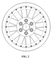
- a lightweight wheel includes a flange 1, a plurality of titanium alloy spokes 2, locking sleeves 3, steel sleeves 4, a connecting ring 5, connecting bolts 6 and a carbon fiber rim 7.
- the flange 1 is positioned at an inner middle part of the carbon fiber rim 7, the plurality of titanium alloy spokes 2 are connected between the flange 1 and the carbon fiber rim 7, and the plurality of titanium alloy spokes 2 are uniformly distributed in pairs along the circumference; and an end of each of the titanium alloy spokes 2 combined in pairs is fixed on the flange 1 in a centralized mode, and another end is fixed separately at the carbon fiber rim 7, making the titanium alloy spokes combined in pairs a fan shape.
- the carbon fiber rim 7 and the titanium alloy spokes 2 in the wheel are formed in such a way as to effectively reduce the overall weight of the wheel.
- each titanium alloy spoke 2 is provided with threads 6-2, another end is bent and provided with a flat end 6-1, and each flat end 6-1 is provided with a first assembly hole.
- the side wall of the flange 1 is provided with two layers of ring grooves 3-1 with one above the other, each layer of ring groove 3-1 is provided with a plurality of threaded holes 3-2uniformly distributed, an end of each of the first assembly holes of the titanium alloy spoke 2 is mounted on a ring groove3-1 through bolt fastened in the threaded hole 3-2 of the ring groove 3-1, the bolt is fastened in the threaded hole 3-2 of the ring groove 3-1 and passthrough the first assembly hole to mount the flat end 6-1 of the titanium alloy spoke 2 on the ring groove 3-1, and the positions of the threaded holes in the upper layer of ring groove are in one-to-one correspondence to the positions of the threaded holes in the lower layer of ring groove in the vertical direction.
- the titanium alloy spokes 2 Due to the fact that the flange 1 and the titanium alloy spokes 2 are connected through the ring grooves 3-1, the titanium alloy spokes 2 have the freedom of movement in the circumferential direction of the ring grooves 3-1, thus effectively reducing the assembly difficulty and processing cost of the titanium alloy spokes 2.
- the inner side of the middle part of the carbon fiber rim 7 is provided with a ring-shaped boss, and a plurality of second assembly holes are uniformly distributed in the ring-shaped boss.
- the outer side of the upper end of the connecting ring 5 is provided with an annular boss, a plurality of second mounting holes 8-2 are uniformly formed in the annular boss, and perforated by the annular boss vertically, and the lower end of the connecting ring 5 is uniformly provided with a plurality of first mounting holes 8-1 and perforated by the first mounting holes horizontally.
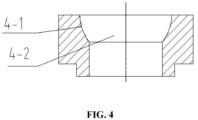
- the side wall and the upper end face of the connecting ring 5 are respectively provided with a plurality of first mounting holes 8-1 and a plurality of second mounting holes 8-2 which are uniformly distributed, the steel sleeves 4 are mounted in the first mounting holes 8-1, a plurality of first inner holes are formed in the steel sleeves 4, and the first inner holes on an outer side of each of the steel sleeves are spherical surfaces, for details, see the spherical surface of first inner hole of steel sleeve (4-1) and the first inner hole of steel sleeve (4-2) in FIG. 4 .
- the first mounting holes 8-1 each have a small inside diameter and a large outside diameter
- the steel sleeves 4 are adapted to the first mounting holes 8-1 in shape
- the steel sleeves 4 each have a small inside diameter and a large outside diameter
- the first inner holes on the outer side of each of the steel sleeves 4 is provided with a spherical surface.
- the connecting bolts 6 passthrough the second mounting holes 8-2 and the second assembly holes and are matched with to fix the carbon fiber rim 7 and the connecting ring 5.
- the number of the titanium alloy spokes 2, the number of the second assembly holes, the number of the first mounting holes 8-1, the number of the second mounting holes 8-2, and the total number of the threaded holes 3-2 in the two layers of ring grooves are all equal.
- the positions of the first mounting holes 8-1 are in one-to-one correspondence to the positions of the second mounting holes8-2 in the vertical direction.
- Each locking sleeve 3 includes a spherical surface at the upper end and a structural surface at the lower end, a plurality of second inner holes are formed in the locking sleeves 3 in a vertically through manner, the upper side wall of each of the locking sleeves 3 is provided with a spherical surface, and the upper side wall of each of the locking sleeves 3 is mounted in the first inner holes of the steel sleeves 4 and is matched with the spherical surface of the first inner hole of each of the steel sleeves 4.
- the second inner hole formed in each locking sleeve 3 see the structure of a locking sleeve 3 in FIG.
- 5 herein reference sign 5-1 denotes the structural surface of the locking sleeve, 5-2 denotes the second inner hole of the locking sleeve, and 5-3 denotes the spherical surface of the locking sleeve.
- the second inner hole of each locking sleeve 3 is a threaded hole, the second inner hole of each locking sleeve 3 is matched with the threads at one end of the corresponding titanium alloy spoke 2 to fix an end of the titanium alloy spoke 2 to the second inner hole of the locking sleeve 3, and the tightness of the titanium alloy spoke 2 can be adjusted by matching a special tool for tightening with the structural surface of the locking sleeve 3androtating the locking sleeve 3.By means of the matching of the spherical surface of the first inner hole of each of the steel sleeves 4 and the spherical surface of the upper side wall of each of the locking sleeves 3, the locking sleeves 3 and the titanium alloy spokes 2 can rotate around the spherical centers of the steel sleeves 4 within a certain range, and the structure can realize the spatial layout of the titanium alloy spokes 2, thereby meeting the requirements on strength, appearance and the like of wheels.
- a series of locking sleeves 3 are enabled to pass through the steel sleeves 4, the spherical surfaces of the first inner holes of the steel sleeves 4 are matched with the spherical surface of the upper side walls of the locking sleeves 3, at the same time, threads on the second inner holes of the locking sleeves 3 are meshed with the threaded ends of the titanium alloy spokes 2, the locking sleeves 3 are sequentially rotated by a special tool to adjust the tightness of the titanium alloy spokes, and the requirement on the coaxiality of the center of the flange and the connecting ring 5 is met. Finally, the assembled connecting ring 5 is mounted on the carbon fiber rim 7 through the matching of the specific connecting bolts 6 and nuts. In this way, the titanium alloy spoke and carbon fiber rim lightweight wheel is obtained.
- An automobile adopts the lightweight wheel in First Embodiment.
- the service life of a tire is prolonged, and the running safety of the automobile is effectively guaranteed; meanwhile, the weight of the wheel is further reduced, so that under the same power, the braking performance of the wheel is more sensitive compared with that of a pure aluminum alloy hub, the damping effect is better, and the oil consumption is lower.
- the invention provides lightweight wheels and an automobile.
- the plurality of titanium alloy spokes are adopted to connect and fix the flange and the carbon fiber rim, and the titanium alloy spokes ensure the structural strength of the wheel; meanwhile, the weight of the wheel is reduced, the heat dissipation effect is good, the service life of the tire is prolonged, and the running safety of the automobile is effectively guaranteed;
- the carbon fiber rim ensures the structural strength of the wheel and further reduces the weight of the wheel, so that under the same power, the braking performance of the wheel is more sensitive compared with that of a pure aluminum alloy hub, the damping effect is better, and the oil consumption is lower;
- a connecting structure of the locking sleeves, steel sleeves and the connecting ring is specifically designed, so that the assembly difficulty and processing cost of the titanium alloy spokes are effectively reduced, and the spatial layout of the titanium alloy spokes can be realized, thus meeting the requirements on strength, appearance and the like of the wheel; besides, the design of the connecting parts and the structure effectively reduces the overall weight of the wheel, ensures the
- the lightweight wheel adopts a split design, which allows damaged parts to be replaced separately, thus greatly reducing the maintenance and replacement costs and being more beneficial to the promotion of the wheel.
- the automobile adopting the lightweight wheel can have a longer service life of the tire, thus effectively ensuring the running safety of the automobile; meanwhile, the weight of the wheel is further reduced, so that under the same power, the braking performance of the wheel is more sensitive compared with that of a pure aluminum alloy hub, the damping effect is better, and the oil consumption is lower.
Landscapes
- Engineering & Computer Science (AREA)
- Mechanical Engineering (AREA)
- Tires In General (AREA)
- Regulating Braking Force (AREA)
- Rolling Contact Bearings (AREA)
Claims (8)
- Leichtes Rad, umfassend einen Flansch (1), eine Mehrzahl von Titanlegierungsspeichen (2), Verriegelungshülsen (3), Stahlhülsen (4) und eine Felge (7), wobei ein Ende jeder Titanlegierungsspeiche (2) mit Gewinden (6-2) versehen ist, wobei der Flansch (1) an einem mittleren Teil der Felge (7) positioniert ist,
dadurch gekennzeichnet, dass das Rad ferner Verbindungsschrauben(6) umfasst, dass die Felge aus Kohlefaser besteht, und
dass ein anderes Ende jeder Titanlegierungsspeiche (2) gebogen und mit einem flachen Ende (6-1) versehen ist, und jedes flache Ende (6-1) mit einem ersten Montageloch versehen ist; dass eine Seitenwand des Flansches (1) mit zwei übereinander liegende Schichten von Ringnuten (3-1) versehen ist, wobei jede Schicht von Ringnuten (3-1) mit einer Mehrzahl von gleichmäßig verteilte Gewindebohrungen (3-2) versehen ist; dass eine Mehrzahl von Schrauben in den Gewindebohrungen (3-2) jeder Schicht von Ringnuten (3-1) eingeschraubt sind und durch die ersten Montagelöcher durchgeführt sind, um die flachen Enden (6-1) der Titanlegierungsspeichen (2) auf der Ringnut (3-1) zu montieren; dass eine Innenseite des mittleren Teils der Kohlefaserfelge (7) mit einem ringförmigen Vorsprung versehen ist, und eine Mehrzahl von zweiten Montagelöchern gleichmäßig in dem ringförmigen Vorsprung verteilt sind; dass das leichte Rad ferner einen Verbindungsring (5) umfasst, wobei die Seitenwand und die obere Stirnfläche des Verbindungsrings (5) jeweils mit einer Mehrzahl von ersten Befestigungslöchern (8-1) und einer Mehrzahl von zweiten Befestigungslöchern (8-2) versehen sind, die gleichmäßig verteilt sind, wobei die Stahlhülsen (4) in jeder der Mehrzahl der ersten Befestigungslöcher (8-1) montiert sind, dass in jeder der Stahlhülsen (4) ein erstes Innenloch gebildet ist, und das erste Innenloch jeder der Stahlhülsen (4) mit einer kugelförmigen Oberfläche versehen ist; dass eine Verbindungsschraube (6) durch die zweiten Befestigungslöcher (8-2) und die zweiten Montagelöcher durchgeführt ist, um die Kohlefaserfelge (7) und der Verbindungsring (5) zu befestigen; dass eine obere Seitenwand jeder der Verriegelungshülsen (3) mit einer kugelförmigen Oberfläche versehen ist, die obere Seitenwände der Verriegelungshülsen (3) in das erste Innenloch jeder der Stahlhülsen (4) montiert sind und der kugelförmigen Oberflächen der ersten Innenlöcher der Stahlhülsen (4) angepasst sind, und in jeder der Verriegelungshülsen (3) ein zweites Innenloch gebildet ist; und dass das zweite Innenloch jeder der Verriegelungshülsen (3) ein Gewindeloch (3-2) ist, und die zweiten Innenlöcher der Verriegelungshülsen (3) dem Gewinde (6-2) an einem Ende jeder der Titanlegierungsspeichen (2) angepasst sind, um das Ende jeder der Titanlegierungsspeichen (2) an jedem der Innenlöcher der Verriegelungshülsen (3) zu befestigen. - Leichtes Rad nach Anspruch 1, wobei jede Verriegelungshülse (3) eine kugelförmige Oberfläche an einem oberen Ende und eine strukturierte Oberfläche an einem unteren Ende aufweist, das zweite Innenloch in jeder der Verriegelungshülsen (3) vertikal durchgehend ausgebildet ist, und die Dichtigkeit jeder Titanlegierungsspeiche (2) durch Anpassung eines speziellen Werkzeugs zum Anziehen an der strukturierten Oberfläche einer Verriegelungshülse (3) und durch Drehung der Verriegelungshülse (3) eingestellt werden kann.
- Leichtes Rad nach Anspruch 1, wobei die Anzahl der Titanlegierungsspeichen (2), die Anzahl der zweiten Montagelöcher, die Anzahl der ersten Befestigungslöcher (8-1), die Anzahl der zweiten Befestigungslöcher (8-2) und die Gesamtzahl der Gewindelöcher (3-2) in den beiden Schichten von Ringnuten (3-1) alle gleich sind.
- Leichtes Rad nach Anspruch 1, wobei ein oberes Ende des Verbindungsrings (5) mit einem Ringvorsprung auf Außenseite des oberen Endes versehen ist, der Ringvorsprung mit der Mehrzahl von zweiten Befestingslöchern (8-2) versehen ist und durch die zweiten Befestigungslöcher (8-2) vertikal perforiert ist, und ein unteres Ende des Verbindungsrings (5) gleichmäßig mit der Mehrzahl von ersten Befestigungslöchern (8-1) versehen ist und durch die ersten Befestigungslöcher (8-1) horizontal perforiert ist.
- Leichtes Rad nach Anspruch 4, wobei die ersten Befestigungslöcher (8-1) jeweils einen kleinen Innendurchmesser und einen großen Außendurchmesser aufweisen, die Stahlhülsen (4) in Form an die ersten Befestigungslöcher (8-1) angepasst sind, die Stahlhülsen (4) jeweils einen kleinen Innendurchmesser und einen großen Außendurchmesser aufweisen, und das erste Innenloch jeder der Stahlhülsen (4) mit einer kugelförmigen Oberfläche versehen ist.
- Leichtes Rad nach Anspruch 1, wobei die Positionen der ersten Befestigungslöcher (8-1) den Positionen der zweiten Befestigungslöcher (8-2) in der vertikalen Richtung in Eins-zu-Eins-Korrespondenz entsprechen.
- Leichtes Rad nach einem der Ansprüche 1-5, wobei die Positionen der Gewindelöcher (3-2) in der oberen Schicht der Ringnuten (3-1) den Positionen der Gewindelöcher (3-2) in der unteren Schicht der Ringnuten (3-1) in der vertikalen Richtung in Eins-zu-Eins-Korrespondenz entsprechen.
- Fahrzeug, dadurch gekennzeichnet, dass es ein leichtes Rad nach einem der Ansprüche 1-7 umfasst.
Applications Claiming Priority (1)
| Application Number | Priority Date | Filing Date | Title |
|---|---|---|---|
| CN201910565636.3A CN110203008A (zh) | 2019-06-27 | 2019-06-27 | 一种轻量化车轮及汽车 |
Publications (2)
| Publication Number | Publication Date |
|---|---|
| EP3756905A1 EP3756905A1 (de) | 2020-12-30 |
| EP3756905B1 true EP3756905B1 (de) | 2023-05-10 |
Family
ID=67794918
Family Applications (1)
| Application Number | Title | Priority Date | Filing Date |
|---|---|---|---|
| EP19219873.7A Active EP3756905B1 (de) | 2019-06-27 | 2019-12-27 | Leichträder und automobil |
Country Status (4)
| Country | Link |
|---|---|
| US (1) | US11305577B2 (de) |
| EP (1) | EP3756905B1 (de) |
| CN (1) | CN110203008A (de) |
| MA (1) | MA48319A (de) |
Families Citing this family (2)
| Publication number | Priority date | Publication date | Assignee | Title |
|---|---|---|---|---|
| CN110254124B (zh) * | 2019-06-27 | 2024-02-09 | 中信戴卡股份有限公司 | 一种复合车轮及其组装装置 |
| CN110901289A (zh) * | 2019-11-15 | 2020-03-24 | 上海卡多克汽车用品有限公司 | 一种钛合金轮毂及其制造方法 |
Family Cites Families (11)
| Publication number | Priority date | Publication date | Assignee | Title |
|---|---|---|---|---|
| US556124A (en) * | 1896-03-10 | Vehicle-wheel | ||
| US430687A (en) * | 1890-06-24 | eeinhold | ||
| US520845A (en) * | 1894-06-05 | Velocipede-wheel | ||
| US249166A (en) * | 1881-11-08 | Metallic wheel | ||
| FR2745232B1 (fr) * | 1996-02-28 | 1998-04-30 | Mastowski Cyrille | Adaptateur pour le rayonnage de roues a rayons montees avec des pneumatiques sans chambre |
| US6520595B1 (en) * | 1998-12-14 | 2003-02-18 | Raphael Schlanger | Vehicle wheel |
| US6679561B2 (en) | 2001-11-08 | 2004-01-20 | Trek Bicycle Corporation | Paired spoke bicycle wheel with optimized rim extrusion and spoke spacing and components thereof |
| US7192097B2 (en) | 2002-12-26 | 2007-03-20 | Raphael Schlanger | Vehicle wheel |
| US7357460B2 (en) | 2003-01-13 | 2008-04-15 | Raphael Schlanger | Connecting system for tensile elements |
| US20100264722A1 (en) * | 2009-04-17 | 2010-10-21 | Teixeira Iv Charles R | Bicycle rim with mechanical spoke attachment |
| CN201646244U (zh) | 2010-05-13 | 2010-11-24 | 王景山 | 结构改进的碳纤维轮圈 |
-
2019
- 2019-06-27 CN CN201910565636.3A patent/CN110203008A/zh not_active Withdrawn
- 2019-11-25 US US16/693,927 patent/US11305577B2/en active Active
- 2019-12-27 MA MA048319A patent/MA48319A/fr unknown
- 2019-12-27 EP EP19219873.7A patent/EP3756905B1/de active Active
Also Published As
| Publication number | Publication date |
|---|---|
| EP3756905A1 (de) | 2020-12-30 |
| US11305577B2 (en) | 2022-04-19 |
| MA48319A (fr) | 2020-12-30 |
| US20200406670A1 (en) | 2020-12-31 |
| CN110203008A (zh) | 2019-09-06 |
Similar Documents
| Publication | Publication Date | Title |
|---|---|---|
| EP3756905B1 (de) | Leichträder und automobil | |
| US6145936A (en) | Spoke wheel for a tubeless tire | |
| GB2473009A (en) | A wheel hub having a hub centre and end part engaged through complementary formations | |
| CN201587282U (zh) | 车轮配重 | |
| CN109910496B (zh) | 摩托车无内胎辐条式铝合金圈轮组 | |
| CN210191003U (zh) | 一种轻量化车轮及汽车 | |
| US20220297472A1 (en) | Wheel rim assembly | |
| CN205416985U (zh) | 一种装配于牵引车的钢质轮毂 | |
| WO2019201510A1 (en) | Wheel | |
| CN205705961U (zh) | 汽车车轮轮毂 | |
| CN210851871U (zh) | 一种装配式单排全向轮 | |
| CN206171030U (zh) | 一种轮毂以及使用该轮毂的摩托车 | |
| CN213007367U (zh) | 一种车轮配重及具有该车轮配重的拖拉机 | |
| KR870003882A (ko) | 자동차 차륜의 변환 키트와 변환 방법 및 이에 의한 차륜 | |
| CN221585019U (zh) | 具有垫圈结构的车轮和车辆 | |
| WO2007121891A1 (en) | Device for fixing a vehicle wheel to the supporting surface | |
| RU122337U1 (ru) | Колесо | |
| CN107776335B (zh) | 一种机械弹性车轮横向稳定加强型复合轮毂结构 | |
| CN212860937U (zh) | 一种稳定性好的电动车用钢圈 | |
| CN115320775B (zh) | 外转子型轮毂电机及两轮电动平衡车 | |
| CN217198094U (zh) | 一种安装小直径轮毂的碟刹后桥结构 | |
| CN223739487U (zh) | 一种航空发动机中介机匣安装座 | |
| CN221585021U (zh) | 具有连接环的车轮和车辆 | |
| CN209972047U (zh) | 一种含有刹车附件的电动车轮毂 | |
| CN221438267U (zh) | 一种高速电动滑板车电机安装结构 |
Legal Events
| Date | Code | Title | Description |
|---|---|---|---|
| PUAI | Public reference made under article 153(3) epc to a published international application that has entered the european phase |
Free format text: ORIGINAL CODE: 0009012 |
|
| STAA | Information on the status of an ep patent application or granted ep patent |
Free format text: STATUS: REQUEST FOR EXAMINATION WAS MADE |
|
| 17P | Request for examination filed |
Effective date: 20191227 |
|
| AK | Designated contracting states |
Kind code of ref document: A1 Designated state(s): AL AT BE BG CH CY CZ DE DK EE ES FI FR GB GR HR HU IE IS IT LI LT LU LV MC MK MT NL NO PL PT RO RS SE SI SK SM TR |
|
| AX | Request for extension of the european patent |
Extension state: BA ME |
|
| GRAP | Despatch of communication of intention to grant a patent |
Free format text: ORIGINAL CODE: EPIDOSNIGR1 |
|
| STAA | Information on the status of an ep patent application or granted ep patent |
Free format text: STATUS: GRANT OF PATENT IS INTENDED |
|
| INTG | Intention to grant announced |
Effective date: 20230124 |
|
| GRAS | Grant fee paid |
Free format text: ORIGINAL CODE: EPIDOSNIGR3 |
|
| GRAA | (expected) grant |
Free format text: ORIGINAL CODE: 0009210 |
|
| STAA | Information on the status of an ep patent application or granted ep patent |
Free format text: STATUS: THE PATENT HAS BEEN GRANTED |
|
| AK | Designated contracting states |
Kind code of ref document: B1 Designated state(s): AL AT BE BG CH CY CZ DE DK EE ES FI FR GB GR HR HU IE IS IT LI LT LU LV MC MK MT NL NO PL PT RO RS SE SI SK SM TR |
|
| REG | Reference to a national code |
Ref country code: GB Ref legal event code: FG4D |
|
| REG | Reference to a national code |
Ref country code: AT Ref legal event code: REF Ref document number: 1566335 Country of ref document: AT Kind code of ref document: T Effective date: 20230515 Ref country code: CH Ref legal event code: EP |
|
| REG | Reference to a national code |
Ref country code: DE Ref legal event code: R096 Ref document number: 602019028698 Country of ref document: DE |
|
| REG | Reference to a national code |
Ref country code: IE Ref legal event code: FG4D |
|
| REG | Reference to a national code |
Ref country code: LT Ref legal event code: MG9D |
|
| REG | Reference to a national code |
Ref country code: NL Ref legal event code: MP Effective date: 20230510 |
|
| REG | Reference to a national code |
Ref country code: AT Ref legal event code: MK05 Ref document number: 1566335 Country of ref document: AT Kind code of ref document: T Effective date: 20230510 |
|
| PG25 | Lapsed in a contracting state [announced via postgrant information from national office to epo] |
Ref country code: SE Free format text: LAPSE BECAUSE OF FAILURE TO SUBMIT A TRANSLATION OF THE DESCRIPTION OR TO PAY THE FEE WITHIN THE PRESCRIBED TIME-LIMIT Effective date: 20230510 Ref country code: PT Free format text: LAPSE BECAUSE OF FAILURE TO SUBMIT A TRANSLATION OF THE DESCRIPTION OR TO PAY THE FEE WITHIN THE PRESCRIBED TIME-LIMIT Effective date: 20230911 Ref country code: NO Free format text: LAPSE BECAUSE OF FAILURE TO SUBMIT A TRANSLATION OF THE DESCRIPTION OR TO PAY THE FEE WITHIN THE PRESCRIBED TIME-LIMIT Effective date: 20230810 Ref country code: NL Free format text: LAPSE BECAUSE OF FAILURE TO SUBMIT A TRANSLATION OF THE DESCRIPTION OR TO PAY THE FEE WITHIN THE PRESCRIBED TIME-LIMIT Effective date: 20230510 Ref country code: ES Free format text: LAPSE BECAUSE OF FAILURE TO SUBMIT A TRANSLATION OF THE DESCRIPTION OR TO PAY THE FEE WITHIN THE PRESCRIBED TIME-LIMIT Effective date: 20230510 Ref country code: AT Free format text: LAPSE BECAUSE OF FAILURE TO SUBMIT A TRANSLATION OF THE DESCRIPTION OR TO PAY THE FEE WITHIN THE PRESCRIBED TIME-LIMIT Effective date: 20230510 |
|
| PG25 | Lapsed in a contracting state [announced via postgrant information from national office to epo] |
Ref country code: RS Free format text: LAPSE BECAUSE OF FAILURE TO SUBMIT A TRANSLATION OF THE DESCRIPTION OR TO PAY THE FEE WITHIN THE PRESCRIBED TIME-LIMIT Effective date: 20230510 Ref country code: PL Free format text: LAPSE BECAUSE OF FAILURE TO SUBMIT A TRANSLATION OF THE DESCRIPTION OR TO PAY THE FEE WITHIN THE PRESCRIBED TIME-LIMIT Effective date: 20230510 Ref country code: LV Free format text: LAPSE BECAUSE OF FAILURE TO SUBMIT A TRANSLATION OF THE DESCRIPTION OR TO PAY THE FEE WITHIN THE PRESCRIBED TIME-LIMIT Effective date: 20230510 Ref country code: LT Free format text: LAPSE BECAUSE OF FAILURE TO SUBMIT A TRANSLATION OF THE DESCRIPTION OR TO PAY THE FEE WITHIN THE PRESCRIBED TIME-LIMIT Effective date: 20230510 Ref country code: IS Free format text: LAPSE BECAUSE OF FAILURE TO SUBMIT A TRANSLATION OF THE DESCRIPTION OR TO PAY THE FEE WITHIN THE PRESCRIBED TIME-LIMIT Effective date: 20230910 Ref country code: HR Free format text: LAPSE BECAUSE OF FAILURE TO SUBMIT A TRANSLATION OF THE DESCRIPTION OR TO PAY THE FEE WITHIN THE PRESCRIBED TIME-LIMIT Effective date: 20230510 Ref country code: GR Free format text: LAPSE BECAUSE OF FAILURE TO SUBMIT A TRANSLATION OF THE DESCRIPTION OR TO PAY THE FEE WITHIN THE PRESCRIBED TIME-LIMIT Effective date: 20230811 |
|
| PG25 | Lapsed in a contracting state [announced via postgrant information from national office to epo] |
Ref country code: FI Free format text: LAPSE BECAUSE OF FAILURE TO SUBMIT A TRANSLATION OF THE DESCRIPTION OR TO PAY THE FEE WITHIN THE PRESCRIBED TIME-LIMIT Effective date: 20230510 |
|
| PG25 | Lapsed in a contracting state [announced via postgrant information from national office to epo] |
Ref country code: SK Free format text: LAPSE BECAUSE OF FAILURE TO SUBMIT A TRANSLATION OF THE DESCRIPTION OR TO PAY THE FEE WITHIN THE PRESCRIBED TIME-LIMIT Effective date: 20230510 |
|
| PG25 | Lapsed in a contracting state [announced via postgrant information from national office to epo] |
Ref country code: SM Free format text: LAPSE BECAUSE OF FAILURE TO SUBMIT A TRANSLATION OF THE DESCRIPTION OR TO PAY THE FEE WITHIN THE PRESCRIBED TIME-LIMIT Effective date: 20230510 Ref country code: SK Free format text: LAPSE BECAUSE OF FAILURE TO SUBMIT A TRANSLATION OF THE DESCRIPTION OR TO PAY THE FEE WITHIN THE PRESCRIBED TIME-LIMIT Effective date: 20230510 Ref country code: RO Free format text: LAPSE BECAUSE OF FAILURE TO SUBMIT A TRANSLATION OF THE DESCRIPTION OR TO PAY THE FEE WITHIN THE PRESCRIBED TIME-LIMIT Effective date: 20230510 Ref country code: EE Free format text: LAPSE BECAUSE OF FAILURE TO SUBMIT A TRANSLATION OF THE DESCRIPTION OR TO PAY THE FEE WITHIN THE PRESCRIBED TIME-LIMIT Effective date: 20230510 Ref country code: DK Free format text: LAPSE BECAUSE OF FAILURE TO SUBMIT A TRANSLATION OF THE DESCRIPTION OR TO PAY THE FEE WITHIN THE PRESCRIBED TIME-LIMIT Effective date: 20230510 Ref country code: CZ Free format text: LAPSE BECAUSE OF FAILURE TO SUBMIT A TRANSLATION OF THE DESCRIPTION OR TO PAY THE FEE WITHIN THE PRESCRIBED TIME-LIMIT Effective date: 20230510 |
|
| REG | Reference to a national code |
Ref country code: DE Ref legal event code: R097 Ref document number: 602019028698 Country of ref document: DE |
|
| PLBE | No opposition filed within time limit |
Free format text: ORIGINAL CODE: 0009261 |
|
| STAA | Information on the status of an ep patent application or granted ep patent |
Free format text: STATUS: NO OPPOSITION FILED WITHIN TIME LIMIT |
|
| 26N | No opposition filed |
Effective date: 20240213 |
|
| PG25 | Lapsed in a contracting state [announced via postgrant information from national office to epo] |
Ref country code: SI Free format text: LAPSE BECAUSE OF FAILURE TO SUBMIT A TRANSLATION OF THE DESCRIPTION OR TO PAY THE FEE WITHIN THE PRESCRIBED TIME-LIMIT Effective date: 20230510 |
|
| PG25 | Lapsed in a contracting state [announced via postgrant information from national office to epo] |
Ref country code: SI Free format text: LAPSE BECAUSE OF FAILURE TO SUBMIT A TRANSLATION OF THE DESCRIPTION OR TO PAY THE FEE WITHIN THE PRESCRIBED TIME-LIMIT Effective date: 20230510 Ref country code: IT Free format text: LAPSE BECAUSE OF FAILURE TO SUBMIT A TRANSLATION OF THE DESCRIPTION OR TO PAY THE FEE WITHIN THE PRESCRIBED TIME-LIMIT Effective date: 20230510 |
|
| REG | Reference to a national code |
Ref country code: CH Ref legal event code: PL |
|
| PG25 | Lapsed in a contracting state [announced via postgrant information from national office to epo] |
Ref country code: LU Free format text: LAPSE BECAUSE OF NON-PAYMENT OF DUE FEES Effective date: 20231227 |
|
| PG25 | Lapsed in a contracting state [announced via postgrant information from national office to epo] |
Ref country code: MC Free format text: LAPSE BECAUSE OF FAILURE TO SUBMIT A TRANSLATION OF THE DESCRIPTION OR TO PAY THE FEE WITHIN THE PRESCRIBED TIME-LIMIT Effective date: 20230510 |
|
| GBPC | Gb: european patent ceased through non-payment of renewal fee |
Effective date: 20231227 |
|
| REG | Reference to a national code |
Ref country code: BE Ref legal event code: MM Effective date: 20231231 |
|
| PG25 | Lapsed in a contracting state [announced via postgrant information from national office to epo] |
Ref country code: MC Free format text: LAPSE BECAUSE OF FAILURE TO SUBMIT A TRANSLATION OF THE DESCRIPTION OR TO PAY THE FEE WITHIN THE PRESCRIBED TIME-LIMIT Effective date: 20230510 Ref country code: LU Free format text: LAPSE BECAUSE OF NON-PAYMENT OF DUE FEES Effective date: 20231227 |
|
| REG | Reference to a national code |
Ref country code: IE Ref legal event code: MM4A |
|
| PG25 | Lapsed in a contracting state [announced via postgrant information from national office to epo] |
Ref country code: IE Free format text: LAPSE BECAUSE OF NON-PAYMENT OF DUE FEES Effective date: 20231227 |
|
| PG25 | Lapsed in a contracting state [announced via postgrant information from national office to epo] |
Ref country code: GB Free format text: LAPSE BECAUSE OF NON-PAYMENT OF DUE FEES Effective date: 20231227 |
|
| PG25 | Lapsed in a contracting state [announced via postgrant information from national office to epo] |
Ref country code: BE Free format text: LAPSE BECAUSE OF NON-PAYMENT OF DUE FEES Effective date: 20231231 |
|
| PG25 | Lapsed in a contracting state [announced via postgrant information from national office to epo] |
Ref country code: CH Free format text: LAPSE BECAUSE OF NON-PAYMENT OF DUE FEES Effective date: 20231231 |
|
| PG25 | Lapsed in a contracting state [announced via postgrant information from national office to epo] |
Ref country code: IE Free format text: LAPSE BECAUSE OF NON-PAYMENT OF DUE FEES Effective date: 20231227 Ref country code: GB Free format text: LAPSE BECAUSE OF NON-PAYMENT OF DUE FEES Effective date: 20231227 Ref country code: CH Free format text: LAPSE BECAUSE OF NON-PAYMENT OF DUE FEES Effective date: 20231231 Ref country code: BE Free format text: LAPSE BECAUSE OF NON-PAYMENT OF DUE FEES Effective date: 20231231 |
|
| PG25 | Lapsed in a contracting state [announced via postgrant information from national office to epo] |
Ref country code: BG Free format text: LAPSE BECAUSE OF FAILURE TO SUBMIT A TRANSLATION OF THE DESCRIPTION OR TO PAY THE FEE WITHIN THE PRESCRIBED TIME-LIMIT Effective date: 20230510 |
|
| PG25 | Lapsed in a contracting state [announced via postgrant information from national office to epo] |
Ref country code: BG Free format text: LAPSE BECAUSE OF FAILURE TO SUBMIT A TRANSLATION OF THE DESCRIPTION OR TO PAY THE FEE WITHIN THE PRESCRIBED TIME-LIMIT Effective date: 20230510 |
|
| PG25 | Lapsed in a contracting state [announced via postgrant information from national office to epo] |
Ref country code: CY Free format text: LAPSE BECAUSE OF FAILURE TO SUBMIT A TRANSLATION OF THE DESCRIPTION OR TO PAY THE FEE WITHIN THE PRESCRIBED TIME-LIMIT; INVALID AB INITIO Effective date: 20191227 |
|
| PG25 | Lapsed in a contracting state [announced via postgrant information from national office to epo] |
Ref country code: HU Free format text: LAPSE BECAUSE OF FAILURE TO SUBMIT A TRANSLATION OF THE DESCRIPTION OR TO PAY THE FEE WITHIN THE PRESCRIBED TIME-LIMIT; INVALID AB INITIO Effective date: 20191227 |
|
| VS25 | Lapsed in a validation state [announced via postgrant information from nat. office to epo] |
Ref country code: MA Free format text: FAILURE TO ELECT DOMICILE IN THE NATIONAL COUNTRY Effective date: 20230811 |
|
| PG25 | Lapsed in a contracting state [announced via postgrant information from national office to epo] |
Ref country code: TR Free format text: LAPSE BECAUSE OF FAILURE TO SUBMIT A TRANSLATION OF THE DESCRIPTION OR TO PAY THE FEE WITHIN THE PRESCRIBED TIME-LIMIT Effective date: 20230510 |
|
| PGFP | Annual fee paid to national office [announced via postgrant information from national office to epo] |
Ref country code: FR Payment date: 20251230 Year of fee payment: 7 |
|
| PGFP | Annual fee paid to national office [announced via postgrant information from national office to epo] |
Ref country code: DE Payment date: 20251231 Year of fee payment: 7 |