EP3756871A1 - Anti-jet joint structure of connection hose of vehicle air compressor - Google Patents
Anti-jet joint structure of connection hose of vehicle air compressor Download PDFInfo
- Publication number
- EP3756871A1 EP3756871A1 EP20176191.3A EP20176191A EP3756871A1 EP 3756871 A1 EP3756871 A1 EP 3756871A1 EP 20176191 A EP20176191 A EP 20176191A EP 3756871 A1 EP3756871 A1 EP 3756871A1
- Authority
- EP
- European Patent Office
- Prior art keywords
- fitting sleeve
- joint structure
- shoulder
- diameter
- jet
- Prior art date
- Legal status (The legal status is an assumption and is not a legal conclusion. Google has not performed a legal analysis and makes no representation as to the accuracy of the status listed.)
- Withdrawn
Links
Images




Classifications
-
- F—MECHANICAL ENGINEERING; LIGHTING; HEATING; WEAPONS; BLASTING
- F04—POSITIVE - DISPLACEMENT MACHINES FOR LIQUIDS; PUMPS FOR LIQUIDS OR ELASTIC FLUIDS
- F04B—POSITIVE-DISPLACEMENT MACHINES FOR LIQUIDS; PUMPS
- F04B39/00—Component parts, details, or accessories, of pumps or pumping systems specially adapted for elastic fluids, not otherwise provided for in, or of interest apart from, groups F04B25/00 - F04B37/00
- F04B39/12—Casings; Cylinders; Cylinder heads; Fluid connections
- F04B39/123—Fluid connections
-
- B—PERFORMING OPERATIONS; TRANSPORTING
- B60—VEHICLES IN GENERAL
- B60C—VEHICLE TYRES; TYRE INFLATION; TYRE CHANGING; CONNECTING VALVES TO INFLATABLE ELASTIC BODIES IN GENERAL; DEVICES OR ARRANGEMENTS RELATED TO TYRES
- B60C29/00—Arrangements of tyre-inflating valves to tyres or rims; Accessories for tyre-inflating valves, not otherwise provided for
- B60C29/06—Accessories for tyre-inflating valves, e.g. housings, guards, covers for valve caps, locks, not otherwise provided for
- B60C29/062—Accessories for tyre-inflating valves, e.g. housings, guards, covers for valve caps, locks, not otherwise provided for for filling a tyre with particular materials, e.g. liquids
-
- B—PERFORMING OPERATIONS; TRANSPORTING
- B60—VEHICLES IN GENERAL
- B60S—SERVICING, CLEANING, REPAIRING, SUPPORTING, LIFTING, OR MANOEUVRING OF VEHICLES, NOT OTHERWISE PROVIDED FOR
- B60S5/00—Servicing, maintaining, repairing, or refitting of vehicles
- B60S5/04—Supplying air for tyre inflation
-
- B—PERFORMING OPERATIONS; TRANSPORTING
- B29—WORKING OF PLASTICS; WORKING OF SUBSTANCES IN A PLASTIC STATE IN GENERAL
- B29C—SHAPING OR JOINING OF PLASTICS; SHAPING OF MATERIAL IN A PLASTIC STATE, NOT OTHERWISE PROVIDED FOR; AFTER-TREATMENT OF THE SHAPED PRODUCTS, e.g. REPAIRING
- B29C73/00—Repairing of articles made from plastics or substances in a plastic state, e.g. of articles shaped or produced by using techniques covered by this subclass or subclass B29D
- B29C73/16—Auto-repairing or self-sealing arrangements or agents
- B29C73/166—Devices or methods for introducing sealing compositions into articles
-
- B—PERFORMING OPERATIONS; TRANSPORTING
- B29—WORKING OF PLASTICS; WORKING OF SUBSTANCES IN A PLASTIC STATE IN GENERAL
- B29C—SHAPING OR JOINING OF PLASTICS; SHAPING OF MATERIAL IN A PLASTIC STATE, NOT OTHERWISE PROVIDED FOR; AFTER-TREATMENT OF THE SHAPED PRODUCTS, e.g. REPAIRING
- B29C73/00—Repairing of articles made from plastics or substances in a plastic state, e.g. of articles shaped or produced by using techniques covered by this subclass or subclass B29D
- B29C73/02—Repairing of articles made from plastics or substances in a plastic state, e.g. of articles shaped or produced by using techniques covered by this subclass or subclass B29D using liquid or paste-like material
- B29C73/025—Repairing of articles made from plastics or substances in a plastic state, e.g. of articles shaped or produced by using techniques covered by this subclass or subclass B29D using liquid or paste-like material fed under pressure
-
- B—PERFORMING OPERATIONS; TRANSPORTING
- B60—VEHICLES IN GENERAL
- B60C—VEHICLE TYRES; TYRE INFLATION; TYRE CHANGING; CONNECTING VALVES TO INFLATABLE ELASTIC BODIES IN GENERAL; DEVICES OR ARRANGEMENTS RELATED TO TYRES
- B60C25/00—Apparatus or tools adapted for mounting, removing or inspecting tyres
- B60C25/16—Tools for repairing damaged tyres
-
- F—MECHANICAL ENGINEERING; LIGHTING; HEATING; WEAPONS; BLASTING
- F15—FLUID-PRESSURE ACTUATORS; HYDRAULICS OR PNEUMATICS IN GENERAL
- F15B—SYSTEMS ACTING BY MEANS OF FLUIDS IN GENERAL; FLUID-PRESSURE ACTUATORS, e.g. SERVOMOTORS; DETAILS OF FLUID-PRESSURE SYSTEMS, NOT OTHERWISE PROVIDED FOR
- F15B11/00—Servomotor systems without provision for follow-up action; Circuits therefor
- F15B11/06—Servomotor systems without provision for follow-up action; Circuits therefor involving features specific to the use of a compressible medium, e.g. air, steam
- F15B11/064—Servomotor systems without provision for follow-up action; Circuits therefor involving features specific to the use of a compressible medium, e.g. air, steam with devices for saving the compressible medium
-
- F—MECHANICAL ENGINEERING; LIGHTING; HEATING; WEAPONS; BLASTING
- F16—ENGINEERING ELEMENTS AND UNITS; GENERAL MEASURES FOR PRODUCING AND MAINTAINING EFFECTIVE FUNCTIONING OF MACHINES OR INSTALLATIONS; THERMAL INSULATION IN GENERAL
- F16L—PIPES; JOINTS OR FITTINGS FOR PIPES; SUPPORTS FOR PIPES, CABLES OR PROTECTIVE TUBING; MEANS FOR THERMAL INSULATION IN GENERAL
- F16L11/00—Hoses, i.e. flexible pipes
-
- F—MECHANICAL ENGINEERING; LIGHTING; HEATING; WEAPONS; BLASTING
- F16—ENGINEERING ELEMENTS AND UNITS; GENERAL MEASURES FOR PRODUCING AND MAINTAINING EFFECTIVE FUNCTIONING OF MACHINES OR INSTALLATIONS; THERMAL INSULATION IN GENERAL
- F16L—PIPES; JOINTS OR FITTINGS FOR PIPES; SUPPORTS FOR PIPES, CABLES OR PROTECTIVE TUBING; MEANS FOR THERMAL INSULATION IN GENERAL
- F16L19/00—Joints in which sealing surfaces are pressed together by means of a member, e.g. a swivel nut, screwed on, or into, one of the joint parts
- F16L19/005—Joints in which sealing surfaces are pressed together by means of a member, e.g. a swivel nut, screwed on, or into, one of the joint parts comprising locking means for the threaded member
-
- F—MECHANICAL ENGINEERING; LIGHTING; HEATING; WEAPONS; BLASTING
- F16—ENGINEERING ELEMENTS AND UNITS; GENERAL MEASURES FOR PRODUCING AND MAINTAINING EFFECTIVE FUNCTIONING OF MACHINES OR INSTALLATIONS; THERMAL INSULATION IN GENERAL
- F16L—PIPES; JOINTS OR FITTINGS FOR PIPES; SUPPORTS FOR PIPES, CABLES OR PROTECTIVE TUBING; MEANS FOR THERMAL INSULATION IN GENERAL
- F16L19/00—Joints in which sealing surfaces are pressed together by means of a member, e.g. a swivel nut, screwed on, or into, one of the joint parts
- F16L19/02—Pipe ends provided with collars or flanges, integral with the pipe or not, pressed together by a screwed member
- F16L19/0206—Pipe ends provided with collars or flanges, integral with the pipe or not, pressed together by a screwed member the collar not being integral with the pipe
-
- F—MECHANICAL ENGINEERING; LIGHTING; HEATING; WEAPONS; BLASTING
- F16—ENGINEERING ELEMENTS AND UNITS; GENERAL MEASURES FOR PRODUCING AND MAINTAINING EFFECTIVE FUNCTIONING OF MACHINES OR INSTALLATIONS; THERMAL INSULATION IN GENERAL
- F16L—PIPES; JOINTS OR FITTINGS FOR PIPES; SUPPORTS FOR PIPES, CABLES OR PROTECTIVE TUBING; MEANS FOR THERMAL INSULATION IN GENERAL
- F16L27/00—Adjustable joints; Joints allowing movement
- F16L27/02—Universal joints, i.e. with mechanical connection allowing angular movement or adjustment of the axes of the parts in any direction
- F16L27/04—Universal joints, i.e. with mechanical connection allowing angular movement or adjustment of the axes of the parts in any direction with partly-spherical engaging surfaces
-
- F—MECHANICAL ENGINEERING; LIGHTING; HEATING; WEAPONS; BLASTING
- F16—ENGINEERING ELEMENTS AND UNITS; GENERAL MEASURES FOR PRODUCING AND MAINTAINING EFFECTIVE FUNCTIONING OF MACHINES OR INSTALLATIONS; THERMAL INSULATION IN GENERAL
- F16L—PIPES; JOINTS OR FITTINGS FOR PIPES; SUPPORTS FOR PIPES, CABLES OR PROTECTIVE TUBING; MEANS FOR THERMAL INSULATION IN GENERAL
- F16L33/00—Arrangements for connecting hoses to rigid members; Rigid hose-connectors, i.e. single members engaging both hoses
- F16L33/02—Hose-clips
-
- F—MECHANICAL ENGINEERING; LIGHTING; HEATING; WEAPONS; BLASTING
- F16—ENGINEERING ELEMENTS AND UNITS; GENERAL MEASURES FOR PRODUCING AND MAINTAINING EFFECTIVE FUNCTIONING OF MACHINES OR INSTALLATIONS; THERMAL INSULATION IN GENERAL
- F16L—PIPES; JOINTS OR FITTINGS FOR PIPES; SUPPORTS FOR PIPES, CABLES OR PROTECTIVE TUBING; MEANS FOR THERMAL INSULATION IN GENERAL
- F16L35/00—Special arrangements used in connection with end fittings of hoses, e.g. safety or protecting devices
-
- F—MECHANICAL ENGINEERING; LIGHTING; HEATING; WEAPONS; BLASTING
- F16—ENGINEERING ELEMENTS AND UNITS; GENERAL MEASURES FOR PRODUCING AND MAINTAINING EFFECTIVE FUNCTIONING OF MACHINES OR INSTALLATIONS; THERMAL INSULATION IN GENERAL
- F16L—PIPES; JOINTS OR FITTINGS FOR PIPES; SUPPORTS FOR PIPES, CABLES OR PROTECTIVE TUBING; MEANS FOR THERMAL INSULATION IN GENERAL
- F16L37/00—Couplings of the quick-acting type
- F16L37/08—Couplings of the quick-acting type in which the connection between abutting or axially overlapping ends is maintained by locking members
-
- B—PERFORMING OPERATIONS; TRANSPORTING
- B29—WORKING OF PLASTICS; WORKING OF SUBSTANCES IN A PLASTIC STATE IN GENERAL
- B29L—INDEXING SCHEME ASSOCIATED WITH SUBCLASS B29C, RELATING TO PARTICULAR ARTICLES
- B29L2030/00—Pneumatic or solid tyres or parts thereof
-
- B—PERFORMING OPERATIONS; TRANSPORTING
- B60—VEHICLES IN GENERAL
- B60S—SERVICING, CLEANING, REPAIRING, SUPPORTING, LIFTING, OR MANOEUVRING OF VEHICLES, NOT OTHERWISE PROVIDED FOR
- B60S5/00—Servicing, maintaining, repairing, or refitting of vehicles
- B60S5/04—Supplying air for tyre inflation
- B60S5/043—Supplying air for tyre inflation characterised by the inflation control means or the drive of the air pressure system
- B60S5/046—Supplying air for tyre inflation characterised by the inflation control means or the drive of the air pressure system using electrical or electronical means
-
- F—MECHANICAL ENGINEERING; LIGHTING; HEATING; WEAPONS; BLASTING
- F16—ENGINEERING ELEMENTS AND UNITS; GENERAL MEASURES FOR PRODUCING AND MAINTAINING EFFECTIVE FUNCTIONING OF MACHINES OR INSTALLATIONS; THERMAL INSULATION IN GENERAL
- F16L—PIPES; JOINTS OR FITTINGS FOR PIPES; SUPPORTS FOR PIPES, CABLES OR PROTECTIVE TUBING; MEANS FOR THERMAL INSULATION IN GENERAL
- F16L33/00—Arrangements for connecting hoses to rigid members; Rigid hose-connectors, i.e. single members engaging both hoses
- F16L33/22—Arrangements for connecting hoses to rigid members; Rigid hose-connectors, i.e. single members engaging both hoses with means not mentioned in the preceding groups for gripping the hose between inner and outer parts
- F16L33/225—Arrangements for connecting hoses to rigid members; Rigid hose-connectors, i.e. single members engaging both hoses with means not mentioned in the preceding groups for gripping the hose between inner and outer parts a sleeve being movable axially
Definitions
- the present invention relates to an anti-jet joint structure of a connection hose of a vehicle air compressor which is configured to feed chemical adhesive and inflate air into a tire, thus repairing the tire.
- a conventional vehicle air compressor is employed to feed chemical adhesive and air into a broken tire so as to repair the broken tire.
- the vehicle air compressor contains a button arranged on an accommodation box. However, when the button is pressed and a connection hose is not connected with an air nozzle of the tire, the chemical adhesive erupts out of a joint on an end of the connection hose suddenly.
- the present invention has arisen to mitigate and/or obviate the afore-described disadvantages.
- the primary aspect of the present invention is to provide an anti-jet joint structure of a connection hose of a vehicle air compressor which contains an accommodation box configured to accommodate a vehicle air compressor, an adhesive supply can for accommodating chemical adhesive, and at least one connection hose, wherein a respective connection hose has a joint arranged on at least one end of thereof so as to prevent eruption of the chemical adhesive.
- Another aspect of the present invention is to provide an anti-jet joint structure of a connection hose of a vehicle air compressor which contains a first connection assembly and a second assembly, wherein the first connection assembly is connected with or is removed from the second connection assembly having different interior structures and volumes so as to mate with various tires.
- an anti-jet joint structure of a connection hose of a vehicle air compressor comprises: an accommodation box 1, an adhesive supply can 2, and a connection hose 3.
- the accommodation box 1 includes a button 11 arranged on a top thereof and has a coupling orifice 12 defined on a peripheral side of the accommodation box 1, wherein the accommodation box 1 accommodates the vehicle air compressor (not shown).
- the connection hose 3 includes a first joint 31 connected on a first end thereof, and the connection hose 3 includes a second joint 4 fixed on a second end thereof and configured to prevent eruption of chemical adhesive.
- the adhesive supply can 2 is mounted on the coupling orifice 12 of the accommodation box 1, wherein an open segment 21 is formed on a bottom of the adhesive can 2 and faces the coupling orifice 12 of the accommodation box 1, and an edge 22 is adjacent to a top of the adhesive supply can 2.
- the first joint 31 of the connection hose 3 is engaged with a supply hose 23 of the adhesive supply can 2.
- the second joint 4 of the connection hose 3 is screwed with a gas nozzle 9 of the tire 99.
- the vehicle air compressor produces the air to force the chemical adhesive into the tire 99 from the adhesive supply can 2 via the connection hose 3, thus repairing and inflating the air into the tire 99.
- connection hose 3 includes the second joint 4 which is the anti-jet joint structure, and the second joint 4 has a first connection assembly 41 and a second connection assembly 42, wherein the first connection assembly 41 is connected with or is removed from the second connection assembly 42 having different interior structures and volumes so as to mate with various tires, such as the tire 99.
- the first connection assembly 41 includes a first fitting sleeve 5 and a base 6, wherein the first fitting sleeve 5 has a chamber 50 defined therein, a first opening 51 defined on a first end of the first fitting sleeve 5, female threads 510 formed on an inner wall of the first fitting sleeve 5, multiple recesses 511 formed on a distal end of the first opening 51, and a through hole 52 defined on a second end of the first fitting sleeve 5, wherein a rib 521 extends inward from the through hole 52, and the through hole 52 communicates with the chamber 50.
- the base 6 includes a cylindrical room 60, a groove 61 formed on an outer wall of the base 6, a stepped extension 62 extending from the outer wall of the base 6 away from the groove 61, a channel 63 defined on a center of the stepped extension 62 and communicating with the cylindrical room 60, and a first seal ring 64 fitted on the groove 61 of the base 6.
- the stepped extension 62 of the base 6 is inserted into the through hole 52 from the first opening 51 of the first fitting sleeve 5 via the chamber 50 and extends out of the first fitting sleeve 5 to fit with the connection hose 3, and the connection hose 3 and the second joint 4 are connected by a fixing ring 40, as illustrated in FIG. 6 .
- the second connection assembly 42 includes a second fitting sleeve 7 and a valve bolt 8.
- the second fitting sleeve 7 includes a locating segment 71 formed on a first end thereof and having male threads 710, a threaded hole 72 defined on a second end of the second fitting sleeve 7 opposite to the locating segment 71, at least one retainer 712 defined between the locating segment 71 and the threaded hole 72, and a passage 73 extending inside the first end of the second fitting sleeve 7, wherein a diameter of the passage 73 is less than a diameter of the threaded hole 72.
- the second fitting sleeve 7 further includes a first stepped shoulder 74 defined between the threaded hole 72 and the passage 73, a second stepped shoulder 75 extending opposite to the first stepped shoulder 74, a stop shoulder 76 extending opposite to the second stepped shoulder 75 and having an aperture 760.
- a diameter A of the first stepped shoulder 74 is more than a diameter B of the second stepped shoulder 75
- the diameter B of the second stepped shoulder 75 is more than a diameter C of the aperture 760 of the stop shoulder 76.
- the passage 73 has a valve seat 77 extending thereon, a second opening 770 formed on a distal end of the valve seat 77, a conical fence 771 formed on the second opening 770, a circular slit 78 defined between an outer wall of the valve seat 77 and an inner wall of the locating segment 71, and a cavity 79 formed between the valve seat 77 and the locating segment 71, wherein the threaded hole 72, the passage 73, the aperture 760 of the stop shoulder 76, the second opening 770 of the valve seat 77, the circular slit 78, and the cavity 79 communicate with one another.
- the valve bolt 8 is cylindrical and includes a knob 81 formed on an end thereof, and the valve bolt 8 includes multiple indentations 82 separately arranged thereon and includes multiple flanges 83, wherein a respective one flange 83 of the multiple flanges 83 is defined between any two adjacent indentations 82 of the multiple indentations 82, the respective one flange 83 has a tab 85 extending therefrom, and a recessed section 84 is defined among the knob 81 and the multiple flanges 83.
- the valve bolt 8 further includes a spring 86 fitted from the knob 81 to abut against the tab 85, and the valve bolt 8 is accommodated into the passage 73 from the threaded hole 72 so that the spring 86 contacts with the stop shoulder 76 and is surrounded by the second stepped shoulder 75.
- the valve bolt 8 includes a cap 87 fitted on the recessed section 84 of the valve bolt 8, and the cap 87 has a cone-shaped face 871 formed on an outer wall of the cap 87 and configured to abut against a connection portion of the conical fence 771 and the stop shoulder 76.
- the valve bolt 8 includes a locking disc 88 engaged on the recessed section 84 between the cap 87 and the knob 81, a washer 89 having a bore 890 and fitted into the threaded hole 72 of the second fitting sleeve 7 to abut against the first stepped shoulder 74 by ways of the bore 890, wherein the tab 85 of the valve bolt 8 moves in the passage 73 of the first stepped shoulder 74, and a second seal ring 711 is fitted with the locating segment 71 of the second fitting sleeve 7, such that the second seal ring 711, the spring 86, the cap 87, the washer 89, and the locating segment 71 of the second fitting sleeve 7 are accommodated into the first connection assembly 41, wherein the locating segment 71 is screwed with the first opening 51 in which the base 6 is received, in other words, the male threads 710 of the locating segment 71 are screwed with the female threads 510 of the first opening 51 of the first fitting sleeve 5, and
- the diameter A of the first stepped shoulder 74 is equal to the diameter B of the second stepped shoulder 75, and the diameter B of the second stepped shoulder 75 is more than the diameter C of the aperture 760 of the stop shoulder 76.
- valve bolt 8 of the second joint 4 forces a needle 91 of the gas nozzle 9 of the tire 99 to move, hence a valve 92 of the gas nozzle 9 is opened.
- the tab 85 of the valve bolt 8 contacts with the first stepped shoulder 74 of the second fitting sleeve 7, and the valve bolt 8 presses the spring 86 so that the cone-shaped face 871 of the cap 87 removes from the connection portion of the conical fence 771 of the valve seat 77 of the second fitting sleeve 7 and the stop shoulder 76 matingly, and the chemical adhesive flows into the tire from the aperture 760 of the stop shoulder 76 via the channel 63 of the base 6, the cylindrical room 60, the multiple indentations 82 of the valve bolt 8, the passage 73, the bore 890 of the washer 89, the threaded hole 72, and the valve 92 of the gas nozzle 9, thus feeding the chemical adhesive and inflating the air into the tire.
- a nut 720 is accommodated in the second end of the second fitting sleeve 7 opposite to the locating segment 71, and the nut 720 has multiple teeth 721 longitudinally formed on an outer wall thereof, wherein a respective one of multiple cutouts 722 is defined between any two adjacent teeth 721, and the respective one cutout 722 is engaged with a respective one of multiple defining wings 724 of the second fitting sleeve 7, as shown in FIG. 11 , such that the nut 720 is connected with the second fitting sleeve 7 securely.
- FIG. 11 illustrates the first fitting sleeve 7 securely.
- a limitation protrusion 725 is formed on the second end of the second fitting sleeve 7 opposite to the locating segment 71 so as to contact with an external fringe 723 of the nut 720, and the washer 89 is accommodated into the nut 702 to contact with the first stepped shoulder 74 of the second fitting sleeve 7.
- the second joint 4 is fixed on the second end of the connection hose 3 and is configured to feed the chemical adhesive, inflate the air, and prevent eruption of chemical adhesive to the tire 99.
- the first connection assembly 41 of the second joint 4 is connected with or is removed from the second connection assembly 42 of the second joint 4 so as to mate with the tire 99.
Landscapes
- Engineering & Computer Science (AREA)
- Mechanical Engineering (AREA)
- General Engineering & Computer Science (AREA)
- Physics & Mathematics (AREA)
- Fluid Mechanics (AREA)
- Quick-Acting Or Multi-Walled Pipe Joints (AREA)
- Joints That Cut Off Fluids, And Hose Joints (AREA)
- Vehicle Cleaning, Maintenance, Repair, Refitting, And Outriggers (AREA)
Abstract
Description
- The present invention relates to an anti-jet joint structure of a connection hose of a vehicle air compressor which is configured to feed chemical adhesive and inflate air into a tire, thus repairing the tire.
- A conventional vehicle air compressor is employed to feed chemical adhesive and air into a broken tire so as to repair the broken tire. The vehicle air compressor contains a button arranged on an accommodation box. However, when the button is pressed and a connection hose is not connected with an air nozzle of the tire, the chemical adhesive erupts out of a joint on an end of the connection hose suddenly.
- The present invention has arisen to mitigate and/or obviate the afore-described disadvantages.
- The primary aspect of the present invention is to provide an anti-jet joint structure of a connection hose of a vehicle air compressor which contains an accommodation box configured to accommodate a vehicle air compressor, an adhesive supply can for accommodating chemical adhesive, and at least one connection hose, wherein a respective connection hose has a joint arranged on at least one end of thereof so as to prevent eruption of the chemical adhesive.
- Another aspect of the present invention is to provide an anti-jet joint structure of a connection hose of a vehicle air compressor which contains a first connection assembly and a second assembly, wherein the first connection assembly is connected with or is removed from the second connection assembly having different interior structures and volumes so as to mate with various tires.
-
-
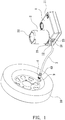
FIG. 1 is a perspective view showing the application of an anti-jet joint structure of a connection hose of a vehicle air compressor according to a preferred embodiment of the present invention. -
FIG. 2 is another perspective view showing the application of the anti-jet joint structure of the connection hose of the vehicle air compressor according to the preferred embodiment of the present invention. -
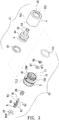
FIG. 3 is a perspective view showing the exploded components of the anti-jet joint structure of the connection hose of the vehicle air compressor according to the preferred embodiment of the present invention. -
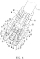
FIG. 4 is a cross-sectional perspective view showing the exploded components of the anti-jet joint structure of the connection hose of the vehicle air compressor according to the preferred embodiment of the present invention. -
FIG. 5 is a side plan view showing the assembly of the anti-jet joint structure of the connection hose of the vehicle air compressor according to the preferred embodiment of the present invention. -
FIG. 6 is a cross sectional view showing the exploded components of the anti-jet joint structure of the connection hose of the vehicle air compressor according to the preferred embodiment of the present invention. -
FIG. 7 is a cross sectional view showing the assembly of the anti-jet joint structure of the connection hose of the vehicle air compressor according to the preferred embodiment of the present invention. -
FIG. 8 is a cross-sectional view showing the operation of the anti-jet joint structure of the connection hose of the vehicle air compressor according to the preferred embodiment of the present invention. -
FIG. 9 is a perspective view showing the exploded components of an anti-jet joint structure of a connection hose of a vehicle air compressor according to another preferred embodiment of the present invention. -
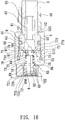
FIG. 10 is a cross sectional view showing the assembly of the anti-jet joint structure of the connection hose of the vehicle air compressor according to another preferred embodiment of the present invention. -
FIG. 11 is another cross sectional view showing the assembly of the anti-jet joint structure of the connection hose of the vehicle air compressor according to another preferred embodiment of the present invention. - With reference to
FIGS. 1-3 , an anti-jet joint structure of a connection hose of a vehicle air compressor according to a preferred embodiment of the present invention comprises: anaccommodation box 1, an adhesive supply can 2, and aconnection hose 3. - The
accommodation box 1 includes abutton 11 arranged on a top thereof and has acoupling orifice 12 defined on a peripheral side of theaccommodation box 1, wherein theaccommodation box 1 accommodates the vehicle air compressor (not shown). Theconnection hose 3 includes afirst joint 31 connected on a first end thereof, and theconnection hose 3 includes asecond joint 4 fixed on a second end thereof and configured to prevent eruption of chemical adhesive. The adhesive supply can 2 is mounted on thecoupling orifice 12 of theaccommodation box 1, wherein anopen segment 21 is formed on a bottom of the adhesive can 2 and faces thecoupling orifice 12 of theaccommodation box 1, and anedge 22 is adjacent to a top of the adhesive supply can 2. Thefirst joint 31 of theconnection hose 3 is engaged with asupply hose 23 of the adhesive supply can 2. When repairing and inflating air into a tire, thesecond joint 4 of theconnection hose 3 is screwed with agas nozzle 9 of thetire 99. After theaccommodation box 1 is started by a power from a vehicle or a DC power supply, the vehicle air compressor produces the air to force the chemical adhesive into thetire 99 from the adhesive supply can 2 via theconnection hose 3, thus repairing and inflating the air into thetire 99. - Referring to
FIGS. 2 ,3 and5 , to prevent the eruption of the chemical adhesive, theconnection hose 3 includes thesecond joint 4 which is the anti-jet joint structure, and thesecond joint 4 has afirst connection assembly 41 and asecond connection assembly 42, wherein thefirst connection assembly 41 is connected with or is removed from thesecond connection assembly 42 having different interior structures and volumes so as to mate with various tires, such as thetire 99. - As shown in
FIGS. 3-8 , thefirst connection assembly 41 includes afirst fitting sleeve 5 and abase 6, wherein thefirst fitting sleeve 5 has achamber 50 defined therein, afirst opening 51 defined on a first end of thefirst fitting sleeve 5,female threads 510 formed on an inner wall of thefirst fitting sleeve 5,multiple recesses 511 formed on a distal end of thefirst opening 51, and a throughhole 52 defined on a second end of thefirst fitting sleeve 5, wherein arib 521 extends inward from the throughhole 52, and the throughhole 52 communicates with thechamber 50. Thebase 6 includes acylindrical room 60, agroove 61 formed on an outer wall of thebase 6, astepped extension 62 extending from the outer wall of thebase 6 away from thegroove 61, achannel 63 defined on a center of thestepped extension 62 and communicating with thecylindrical room 60, and afirst seal ring 64 fitted on thegroove 61 of thebase 6. - The
stepped extension 62 of thebase 6 is inserted into the throughhole 52 from the first opening 51 of thefirst fitting sleeve 5 via thechamber 50 and extends out of thefirst fitting sleeve 5 to fit with theconnection hose 3, and theconnection hose 3 and thesecond joint 4 are connected by afixing ring 40, as illustrated inFIG. 6 . - The
second connection assembly 42 includes asecond fitting sleeve 7 and avalve bolt 8. Thesecond fitting sleeve 7 includes a locatingsegment 71 formed on a first end thereof and havingmale threads 710, a threadedhole 72 defined on a second end of thesecond fitting sleeve 7 opposite to the locatingsegment 71, at least oneretainer 712 defined between the locatingsegment 71 and the threadedhole 72, and apassage 73 extending inside the first end of thesecond fitting sleeve 7, wherein a diameter of thepassage 73 is less than a diameter of the threadedhole 72. Thesecond fitting sleeve 7 further includes a first steppedshoulder 74 defined between the threadedhole 72 and thepassage 73, a second steppedshoulder 75 extending opposite to the first steppedshoulder 74, astop shoulder 76 extending opposite to the second steppedshoulder 75 and having anaperture 760. A diameter A of the first steppedshoulder 74 is more than a diameter B of the second steppedshoulder 75, and the diameter B of the second steppedshoulder 75 is more than a diameter C of theaperture 760 of thestop shoulder 76. Thepassage 73 has avalve seat 77 extending thereon, asecond opening 770 formed on a distal end of thevalve seat 77, aconical fence 771 formed on thesecond opening 770, acircular slit 78 defined between an outer wall of thevalve seat 77 and an inner wall of the locatingsegment 71, and acavity 79 formed between thevalve seat 77 and the locatingsegment 71, wherein the threadedhole 72, thepassage 73, theaperture 760 of thestop shoulder 76, the second opening 770 of thevalve seat 77, thecircular slit 78, and thecavity 79 communicate with one another. Thevalve bolt 8 is cylindrical and includes aknob 81 formed on an end thereof, and thevalve bolt 8 includesmultiple indentations 82 separately arranged thereon and includesmultiple flanges 83, wherein a respective oneflange 83 of themultiple flanges 83 is defined between any twoadjacent indentations 82 of themultiple indentations 82, the respective oneflange 83 has atab 85 extending therefrom, and arecessed section 84 is defined among theknob 81 and themultiple flanges 83. Thevalve bolt 8 further includes aspring 86 fitted from theknob 81 to abut against thetab 85, and thevalve bolt 8 is accommodated into thepassage 73 from the threadedhole 72 so that thespring 86 contacts with thestop shoulder 76 and is surrounded by the second steppedshoulder 75. Thevalve bolt 8 includes acap 87 fitted on therecessed section 84 of thevalve bolt 8, and thecap 87 has a cone-shaped face 871 formed on an outer wall of thecap 87 and configured to abut against a connection portion of theconical fence 771 and thestop shoulder 76. Thevalve bolt 8 includes alocking disc 88 engaged on therecessed section 84 between thecap 87 and theknob 81, awasher 89 having abore 890 and fitted into the threadedhole 72 of thesecond fitting sleeve 7 to abut against the first steppedshoulder 74 by ways of thebore 890, wherein thetab 85 of thevalve bolt 8 moves in thepassage 73 of the first steppedshoulder 74, and asecond seal ring 711 is fitted with the locatingsegment 71 of thesecond fitting sleeve 7, such that thesecond seal ring 711, thespring 86, thecap 87, thewasher 89, and the locatingsegment 71 of thesecond fitting sleeve 7 are accommodated into thefirst connection assembly 41, wherein the locatingsegment 71 is screwed with the first opening 51 in which thebase 6 is received, in other words, themale threads 710 of the locatingsegment 71 are screwed with thefemale threads 510 of the first opening 51 of thefirst fitting sleeve 5, and the at least oneretainer 712 of thesecond fitting sleeve 7 is retained with themultiple recesses 511 of thefirst fitting sleeve 5, as shown inFIGS. 3-5 , hence thefirst connection assembly 41 and thesecond assembly 42 are connected firmly. In another embodiment, the diameter A of the first steppedshoulder 74 is equal to the diameter B of the second steppedshoulder 75, and the diameter B of the second steppedshoulder 75 is more than the diameter C of theaperture 760 of thestop shoulder 76. - With reference to
FIG. 7 , when thebutton 11 of theaccommodation box 1 is pressed so that the chemical adhesive is forced by the air, the cone-shaped face 871 of thecap 87 abuts against the connection portion of theconical fence 771 and thestop shoulder 76 matingly, hence the chemical adhesive is stopped flowing through theaperture 760 of thestop shoulder 76, thus preventing the eruption of the chemical adhesive. - Referring to
FIGS. 1-8 , when the threadedhole 72 of thesecond joint 4 is screwed with thegas nozzle 9 of thetire 99, thevalve bolt 8 of thesecond joint 4 forces aneedle 91 of thegas nozzle 9 of thetire 99 to move, hence avalve 92 of thegas nozzle 9 is opened. In addition, thetab 85 of thevalve bolt 8 contacts with the first steppedshoulder 74 of thesecond fitting sleeve 7, and thevalve bolt 8 presses thespring 86 so that the cone-shaped face 871 of thecap 87 removes from the connection portion of theconical fence 771 of thevalve seat 77 of thesecond fitting sleeve 7 and thestop shoulder 76 matingly, and the chemical adhesive flows into the tire from theaperture 760 of thestop shoulder 76 via thechannel 63 of thebase 6, thecylindrical room 60, themultiple indentations 82 of thevalve bolt 8, thepassage 73, thebore 890 of thewasher 89, the threadedhole 72, and thevalve 92 of thegas nozzle 9, thus feeding the chemical adhesive and inflating the air into the tire. - As shown in
FIGS. 9-11 , in another embodiment, anut 720 is accommodated in the second end of thesecond fitting sleeve 7 opposite to the locatingsegment 71, and thenut 720 hasmultiple teeth 721 longitudinally formed on an outer wall thereof, wherein a respective one ofmultiple cutouts 722 is defined between any twoadjacent teeth 721, and the respective onecutout 722 is engaged with a respective one of multipledefining wings 724 of thesecond fitting sleeve 7, as shown inFIG. 11 , such that thenut 720 is connected with thesecond fitting sleeve 7 securely. As illustrated inFIG. 10 , alimitation protrusion 725 is formed on the second end of thesecond fitting sleeve 7 opposite to the locatingsegment 71 so as to contact with anexternal fringe 723 of thenut 720, and thewasher 89 is accommodated into the nut 702 to contact with the first steppedshoulder 74 of thesecond fitting sleeve 7. - Thereby, the
second joint 4 is fixed on the second end of theconnection hose 3 and is configured to feed the chemical adhesive, inflate the air, and prevent eruption of chemical adhesive to thetire 99. Preferably, thefirst connection assembly 41 of thesecond joint 4 is connected with or is removed from thesecond connection assembly 42 of thesecond joint 4 so as to mate with thetire 99.
Claims (12)
- An anti-jet joint structure of a connection hose (3) of a vehicle air compressor comprising:an accommodation box (1) accommodating the vehicle air compressor started by a power to produce air;an adhesive supply can (2) including an open segment (21) and configured to accommodate chemical adhesive for repairing a tire (99), and the adhesive supply can (2) including a supply hose (23) mounted on the open segment (21); andthe connection hose (3) including a first joint (31) connected on a first end of the connection hose (3), and the connection hose (3) including a second joint (4) fixed on a second end of the connection hose (3), the first joint (31) being engaged with the supply hose (23) of the adhesive supply can (2), and the second joint (4) being screwed with a gas nozzle (9) of the tire (99);wherein the second joint (4) is the anti-jet joint structure and has a first connection assembly (41) and a second connection assembly (42), the first connection assembly (41) is connected with or is removed from the second connection assembly (42) having different interior structures and volumes so as to mate with various tires.
- The anti-jet joint structure as claimed in claim 1, wherein the first connection assembly (41) includes a first fitting sleeve (5) and a base (6), the first fitting sleeve (5) has a chamber (50) defined therein, a first opening (51) defined on a first end of the first fitting sleeve (5), female threads (510) formed on an inner wall of the first fitting sleeve (5), and a through hole (52) defined on a second end of the first fitting sleeve (5), wherein a rib (521) extends inward from the through hole (52), and the through hole (52) communicates with the chamber (50); the base (6) includes a cylindrical room (60), a groove (61) formed on an outer wall of the base (6), a stepped extension (62) extending from the outer wall of the base (6) away from the groove (61), a channel (63) defined on a center of the stepped extension (62) and communicating with the cylindrical room (60), and a first seal ring (711) fitted on the groove (61) of the base (6); the stepped extension (62) of the base (6) is inserted into the through hole (52) from the first opening (51) of the first fitting sleeve (5) via the chamber (50) and extends out of the first fitting sleeve (5) to fit with the connection hose (3), and the connection hose (3) and the second joint (4) are connected by a fixing ring (40).
- The anti-jet joint structure as claimed in claim 2, wherein the second connection assembly (42) includes a second fitting sleeve (7) and a valve bolt (8), the second fitting sleeve (7) includes a locating segment (71) formed on a first end thereof and having male threads (710), a threaded hole (72) defined on a second end of the second fitting sleeve (7) opposite to the locating segment (71), and a passage (73) extending inside the first end of the second fitting sleeve (7), wherein a diameter of the passage (73) is less than a diameter of the threaded hole (72), the second fitting sleeve (7) further includes a first stepped shoulder (74) defined between the threaded hole (72) and the passage (73), a second stepped shoulder (75) extending opposite to the first stepped shoulder (74), a stop shoulder (76) extending opposite to the second stepped shoulder (75) and having an aperture (760), wherein the passage (73) has a valve seat (77) extending thereon, a second opening (770) formed on a distal end of the valve seat (77), a conical fence (771) formed on the second opening (770), a circular slit (78) defined between an outer wall of the valve seat (77) and an inner wall of the locating segment (71), and a cavity (79) formed between the valve seat (77) and the locating segment (71), wherein the threaded hole (72), the passage (73), the aperture (760) of the stop shoulder (76), the second opening (770) of the valve seat (77), the circular slit (78), and the cavity (79) communicate with one another.
- The anti-jet joint structure as claimed in claim 3, wherein a diameter A of the first stepped shoulder (74) is more than a diameter B of the second stepped shoulder (75), and the diameter B of the second stepped shoulder (75) is more than a diameter C of the aperture (760) of the stop shoulder (76).
- The anti-jet joint structure as claimed in claim 3, wherein the valve bolt (8) is cylindrical and includes a knob (81) formed on an end thereof, and the valve bolt (8) includes multiple indentations (82) separately arranged thereon and includes multiple flanges (83), wherein a respective one flange (83) of the multiple flanges (83) is defined between any two adjacent indentations (82) of the multiple indentations (82), the respective one flange (83) has a tab (85) extending therefrom, and a recessed section (84) is defined among the knob (81) and the multiple flanges (83).
- The anti-jet joint structure as claimed in claim 5, wherein the valve bolt (8) further includes a spring (86) fitted from the knob (81) to abut against the tab (85), and the valve bolt (8) is accommodated into the passage (73) from the threaded hole (72) so that the spring (86) contacts with the stop shoulder (76) and is surrounded by the second stepped shoulder (75); wherein the valve bolt (8) includes a cap (87) fitted on the recessed section (84) of the valve bolt (8), and the cap (87) has a cone-shaped face (871) formed on an outer wall of the cap (87) and configured to abut against a connection portion of the conical fence (771) and the stop shoulder (76).
- The anti-jet joint structure as claimed in claim 6, wherein the valve bolt (8) includes a locking disc (88) engaged on the recessed section (84) between the cap (87) and the knob (81).
- The anti-jet joint structure as claimed in claim 5, wherein the tab (85) of the valve bolt (8) moves in the passage (73) of the first stepped shoulder (74).
- The anti-jet joint structure as claimed in claim 6, wherein the valve bolt (8) includes a washer (89) having a bore (890) and fitted into the threaded hole (72) of the second fitting sleeve (7) to abut against the first stepped shoulder (74) by ways of the bore (890); and a second seal ring (64) is fitted with the locating segment (71) of the second fitting sleeve (7), such that the second seal ring (64), the spring (86), the cap (87), the washer (89), and the locating segment (71) of the second fitting sleeve (7) are accommodated into the first connection assembly (41), wherein the locating segment (71) is screwed with the first opening (51) in which the base (6) is received, the male threads (710) of the locating segment (71) are screwed with the female threads (510) of the first opening (51) of the first fitting sleeve (5).
- The anti-jet joint structure as claimed in claim 9, wherein the first fitting sleeve (5) includes multiple recesses (511) formed on a distal end of the first opening (51); at least one retainer (712) defined between the locating segment (71) and the threaded hole (72) of the second fitting sleeve (7), and the at least one retainer (712) of the second fitting sleeve (7) is retained with the multiple recesses (511) of the first fitting sleeve (5).
- The anti-jet joint structure as claimed in claim 3, wherein the diameter A of the first stepped shoulder (74) is equal to the diameter B of the second stepped shoulder (75), and the diameter B of the second stepped shoulder (75) is more than the diameter C of the aperture (760) of the stop shoulder (76).
- The anti-jet joint structure as claimed in claim 3, wherein a nut (720) is accommodated in the second end of the second fitting sleeve (7) opposite to the locating segment (71), and the nut (720) has multiple teeth (721) longitudinally formed on an outer wall thereof, wherein a respective one of multiple cutouts (722) is defined between any two adjacent teeth (721), and the respective one cutout (722) is engaged with a respective one of multiple defining wings (724) of the second fitting sleeve (7), such that the nut (720) is connected with the second fitting sleeve (7), wherein a limitation protrusion (725) is formed on the second end of the second fitting sleeve (7) opposite to the locating segment (71) so as to contact with an external fringe (723) of the nut (720).
Applications Claiming Priority (1)
| Application Number | Priority Date | Filing Date | Title |
|---|---|---|---|
| TW108118851A TWI709500B (en) | 2019-05-30 | 2019-05-30 | Anti-jet joint structure of connection hose of vehicle air compressor |
Publications (1)
| Publication Number | Publication Date |
|---|---|
| EP3756871A1 true EP3756871A1 (en) | 2020-12-30 |
Family
ID=70847232
Family Applications (1)
| Application Number | Title | Priority Date | Filing Date |
|---|---|---|---|
| EP20176191.3A Withdrawn EP3756871A1 (en) | 2019-05-30 | 2020-05-22 | Anti-jet joint structure of connection hose of vehicle air compressor |
Country Status (7)
| Country | Link |
|---|---|
| US (1) | US11235629B2 (en) |
| EP (1) | EP3756871A1 (en) |
| JP (2) | JP6986594B2 (en) |
| KR (1) | KR102344548B1 (en) |
| CN (2) | CN213039423U (en) |
| DE (1) | DE202020102918U1 (en) |
| TW (1) | TWI709500B (en) |
Families Citing this family (11)
| Publication number | Priority date | Publication date | Assignee | Title |
|---|---|---|---|---|
| WO2020097921A1 (en) * | 2018-11-16 | 2020-05-22 | 冠翔(香港)工业有限公司 | Pipe connector assembly and tire maintenance apparatus having same |
| TWI709500B (en) * | 2019-05-30 | 2020-11-11 | 周文三 | Anti-jet joint structure of connection hose of vehicle air compressor |
| TWM597716U (en) * | 2019-06-26 | 2020-07-01 | 周文三 | Supporting device for glue fixer |
| TWI732292B (en) * | 2019-09-12 | 2021-07-01 | 周文三 | Anti-spray joint structure for tire and connection hose of vehicle air compressor |
| TWI722566B (en) * | 2019-09-12 | 2021-03-21 | 周文三 | Anti-spray structure for joint of gas nozzle of tire of vehicle and air compressor |
| USD996211S1 (en) * | 2020-05-18 | 2023-08-22 | Illinois Tool Works Inc. | Sealant bottle cap |
| TWD215928S (en) * | 2021-02-05 | 2021-12-11 | 周文三 | Tire repair and inflator |
| TWD218381S (en) * | 2021-06-16 | 2022-04-21 | 周文三 | Air compressor device for filling glue |
| US12179519B2 (en) * | 2022-01-07 | 2024-12-31 | Arvinmeritor Technology, Llc | Axle assembly having a spindle plug and a sleeve |
| KR102566151B1 (en) * | 2023-01-02 | 2023-08-10 | 박찬역 | loat for marine culture |
| CN118757624B (en) * | 2024-07-30 | 2026-02-06 | 中山密盾气动科技有限公司 | Joint with sealing function and automation equipment |
Citations (10)
| Publication number | Priority date | Publication date | Assignee | Title |
|---|---|---|---|---|
| US1484342A (en) * | 1919-04-05 | 1924-02-19 | Schweinert Maximilian Charles | Adapter for pump couplings |
| EP0743203A1 (en) * | 1995-05-15 | 1996-11-20 | innovative technik marketing (itm) | Adapter device |
| DE20010544U1 (en) * | 2000-06-13 | 2001-02-22 | Völker, Johannes, 34628 Willingshausen | Adapter for bicycle light pump valves |
| DE202006002485U1 (en) * | 2006-02-15 | 2006-04-13 | Golikov, Andrej | Valve for a pneumatic tire comprises a unit which serves for connecting the valve to a gas outlet of a pneumatic pressure source, and incorporates a circumferential engagement flange |
| DE102006007211A1 (en) * | 2006-02-15 | 2007-08-23 | Andrej Golikov | Valve for inflation of a pneumatic tire, with a connection to the compressed air supply, has a peripheral flange to act as a snap coupling in a non-return valve structure |
| EP2390502A1 (en) * | 2009-07-17 | 2011-11-30 | Ying-Che Huang | Inflation nozzle capable of connecting with two types of tire valves |
| DE202012100671U1 (en) * | 2011-03-10 | 2012-06-26 | Wen-San Jhou | Device for sealing and inflating inflatable objects |
| DE202012103464U1 (en) * | 2011-11-02 | 2012-12-20 | Wen-San Jhou | From a vehicle entrained air compression device |
| DE202013101644U1 (en) * | 2012-04-27 | 2013-08-09 | Wen-San Jhou | From a vehicle entrained air compression device |
| DE202018107206U1 (en) * | 2017-12-25 | 2019-01-11 | Unik World Industrial Co., Ltd. | Design of a back-up fuse adapter for connection to a flexible connection hose of a vehicle-carried air compression device for repairing and filling damaged tires |
Family Cites Families (25)
| Publication number | Priority date | Publication date | Assignee | Title |
|---|---|---|---|---|
| US6260572B1 (en) * | 2000-03-28 | 2001-07-17 | Scott Wu | Valve-coupling device for an inflation device |
| US6904932B1 (en) * | 2002-10-01 | 2005-06-14 | Trek Bicycle Corporation | Pump valve adapter |
| TW581150U (en) * | 2003-03-26 | 2004-03-21 | Kurt Kemppainen | Inflating device |
| US20080190489A1 (en) * | 2007-02-13 | 2008-08-14 | Eqair, Llc | Chuck for tire inflation valve |
| DE202007007228U1 (en) * | 2007-05-21 | 2007-09-27 | Huang, Ying-Che | Pump connection for Presta valve |
| WO2009119317A1 (en) * | 2008-03-25 | 2009-10-01 | 住友ゴム工業株式会社 | Tire puncture repair apparatus |
| US7963297B2 (en) * | 2008-07-23 | 2011-06-21 | Ying-Che Huang | Dispensing head for air pump |
| TWI482908B (en) * | 2011-03-07 | 2015-05-01 | 周文三 | Air compressor for vehicle |
| TW201317456A (en) * | 2011-10-26 | 2013-05-01 | ying-zhe Huang | Assembled inflation nozzle |
| TWM462676U (en) * | 2013-05-03 | 2013-10-01 | 冠翔(香港)工業有限公司 | Quick connection and separation device for tire repairing machine |
| CN202972258U (en) * | 2012-10-09 | 2013-06-05 | 张东伟 | Automatically pneumatic tire repair fluid connector of tire |
| TWM453735U (en) * | 2012-11-06 | 2013-05-21 | Wen-San Chou | Joint structure of cascaded hose for vehicle-mounted air compressor |
| US10029429B2 (en) * | 2013-11-28 | 2018-07-24 | Sumitomo Rubber Industries, Ltd. | Apparatus for sealing and/or inflating objects and self-closing screw coupling |
| US9193229B2 (en) * | 2013-12-03 | 2015-11-24 | Top Alliance Technology Limited | Tire repair device |
| TWI583572B (en) * | 2014-11-18 | 2017-05-21 | 周文三 | First aid device for broken tires |
| TWI647129B (en) * | 2015-04-23 | 2019-01-11 | 周文三 | Air compressor |
| CN205779525U (en) * | 2016-06-21 | 2016-12-07 | 中国石油化工股份有限公司 | Oil field blowout preventer manual pressure test pump and manual pressure testing device |
| CN206012565U (en) * | 2016-08-22 | 2017-03-15 | 黄伟勤 | A kind of inflating and tire-patching device and its Multifunctional inflating joint |
| CN206361159U (en) * | 2016-12-29 | 2017-07-28 | 陈洪明 | A kind of multi-functional puncture-mending liquid connector |
| EP3661769A1 (en) * | 2017-08-03 | 2020-06-10 | Trydel Research Pty. Ltd. | Improvements to tire repair apparatus |
| US20190100062A1 (en) * | 2017-09-29 | 2019-04-04 | Mould Flying Industrial Co., Ltd. | Screw-in valve connector |
| TWM572946U (en) * | 2017-12-25 | 2019-01-11 | 已久工業股份有限公司 | Check connector structure of connection hose for vehicle air compressor |
| CN109139425A (en) * | 2018-11-05 | 2019-01-04 | 南通市红星空压机配件制造有限公司 | Oil-injection-preventing air inlet valve for electric bus air compressor |
| TWI709500B (en) * | 2019-05-30 | 2020-11-11 | 周文三 | Anti-jet joint structure of connection hose of vehicle air compressor |
| TWM594660U (en) * | 2019-05-30 | 2020-05-01 | 周文三 | Anti-eruption joint structure of tandem hose of vehicle-mounted air compressor |
-
2019
- 2019-05-30 TW TW108118851A patent/TWI709500B/en not_active IP Right Cessation
-
2020
- 2020-05-11 KR KR1020200055723A patent/KR102344548B1/en active Active
- 2020-05-20 DE DE202020102918.5U patent/DE202020102918U1/en active Active
- 2020-05-22 EP EP20176191.3A patent/EP3756871A1/en not_active Withdrawn
- 2020-05-25 US US16/882,715 patent/US11235629B2/en active Active
- 2020-05-26 JP JP2020091064A patent/JP6986594B2/en active Active
- 2020-05-26 JP JP2020001937U patent/JP3229635U/en active Active
- 2020-05-29 CN CN202020946948.7U patent/CN213039423U/en active Active
- 2020-05-29 CN CN202010474439.3A patent/CN112012909A/en not_active Withdrawn
Patent Citations (11)
| Publication number | Priority date | Publication date | Assignee | Title |
|---|---|---|---|---|
| US1484342A (en) * | 1919-04-05 | 1924-02-19 | Schweinert Maximilian Charles | Adapter for pump couplings |
| EP0743203A1 (en) * | 1995-05-15 | 1996-11-20 | innovative technik marketing (itm) | Adapter device |
| EP0743203B1 (en) * | 1995-05-15 | 1999-08-04 | innovative technik marketing (itm) | Adapter device |
| DE20010544U1 (en) * | 2000-06-13 | 2001-02-22 | Völker, Johannes, 34628 Willingshausen | Adapter for bicycle light pump valves |
| DE202006002485U1 (en) * | 2006-02-15 | 2006-04-13 | Golikov, Andrej | Valve for a pneumatic tire comprises a unit which serves for connecting the valve to a gas outlet of a pneumatic pressure source, and incorporates a circumferential engagement flange |
| DE102006007211A1 (en) * | 2006-02-15 | 2007-08-23 | Andrej Golikov | Valve for inflation of a pneumatic tire, with a connection to the compressed air supply, has a peripheral flange to act as a snap coupling in a non-return valve structure |
| EP2390502A1 (en) * | 2009-07-17 | 2011-11-30 | Ying-Che Huang | Inflation nozzle capable of connecting with two types of tire valves |
| DE202012100671U1 (en) * | 2011-03-10 | 2012-06-26 | Wen-San Jhou | Device for sealing and inflating inflatable objects |
| DE202012103464U1 (en) * | 2011-11-02 | 2012-12-20 | Wen-San Jhou | From a vehicle entrained air compression device |
| DE202013101644U1 (en) * | 2012-04-27 | 2013-08-09 | Wen-San Jhou | From a vehicle entrained air compression device |
| DE202018107206U1 (en) * | 2017-12-25 | 2019-01-11 | Unik World Industrial Co., Ltd. | Design of a back-up fuse adapter for connection to a flexible connection hose of a vehicle-carried air compression device for repairing and filling damaged tires |
Also Published As
| Publication number | Publication date |
|---|---|
| JP3229635U (en) | 2020-12-17 |
| KR20200138657A (en) | 2020-12-10 |
| US11235629B2 (en) | 2022-02-01 |
| US20200376908A1 (en) | 2020-12-03 |
| TW202043079A (en) | 2020-12-01 |
| CN213039423U (en) | 2021-04-23 |
| CN112012909A (en) | 2020-12-01 |
| JP6986594B2 (en) | 2021-12-22 |
| TWI709500B (en) | 2020-11-11 |
| KR102344548B1 (en) | 2021-12-28 |
| DE202020102918U1 (en) | 2020-08-13 |
| JP2020197302A (en) | 2020-12-10 |
Similar Documents
| Publication | Publication Date | Title |
|---|---|---|
| US11235629B2 (en) | Anti-jet joint structure of connection hose of vehicle air compressor | |
| US11052621B2 (en) | Combination structure for a hose connected between an air compressor and a tire | |
| US11548333B2 (en) | Check joint structure for connection of air nozzle of tire and connection hose of air compressor | |
| EP3797977A1 (en) | Anti-spray joint structure for connection of air nozzle of tire and connection hose of air compressor | |
| US11046128B2 (en) | Anti-spray structure for conention of air nozzle of tire of vehicle and conenction hose of air compressor | |
| US20140174563A1 (en) | Internal pilot type pressure regulator | |
| US20210016616A1 (en) | Air compressor capable of inflating air and supplying sealant | |
| EP3797976A1 (en) | Anti-spray joint structure of connection hose of vehicle air compressor | |
| CN112867885A (en) | Valve core | |
| US4616677A (en) | Manifold fitting for a compressed air tank | |
| US20200101487A1 (en) | Sealant dispenser | |
| US11358351B2 (en) | Anti-spray joint structure of connection hose of vehicle air compressor | |
| US11149892B2 (en) | Check structure for connection of air nozzle of tire and connection hose of air compressor | |
| US11143346B2 (en) | Check joint structure for connection of an air nozzle of a tire and a connector of a connection hose of an air compressor | |
| US10807107B2 (en) | Control structure capable of adjusting water volume and controlling water supply | |
| JP7093537B2 (en) | Fuel container for gas-burning driving tools | |
| KR200421703Y1 (en) | Atomizer hose connection structure | |
| JP2006298198A (en) | Valve for automatic air supply | |
| JP2018052593A (en) | Discharge container |
Legal Events
| Date | Code | Title | Description |
|---|---|---|---|
| PUAI | Public reference made under article 153(3) epc to a published international application that has entered the european phase |
Free format text: ORIGINAL CODE: 0009012 |
|
| STAA | Information on the status of an ep patent application or granted ep patent |
Free format text: STATUS: REQUEST FOR EXAMINATION WAS MADE |
|
| 17P | Request for examination filed |
Effective date: 20200826 |
|
| AK | Designated contracting states |
Kind code of ref document: A1 Designated state(s): AL AT BE BG CH CY CZ DE DK EE ES FI FR GB GR HR HU IE IS IT LI LT LU LV MC MK MT NL NO PL PT RO RS SE SI SK SM TR |
|
| AX | Request for extension of the european patent |
Extension state: BA ME |
|
| STAA | Information on the status of an ep patent application or granted ep patent |
Free format text: STATUS: EXAMINATION IS IN PROGRESS |
|
| 17Q | First examination report despatched |
Effective date: 20230314 |
|
| STAA | Information on the status of an ep patent application or granted ep patent |
Free format text: STATUS: THE APPLICATION HAS BEEN WITHDRAWN |
|
| 18W | Application withdrawn |
Effective date: 20230522 |