EP3756628B1 - Anordnungen zum einsetzen von biliären stents - Google Patents
Anordnungen zum einsetzen von biliären stents Download PDFInfo
- Publication number
- EP3756628B1 EP3756628B1 EP20150001.4A EP20150001A EP3756628B1 EP 3756628 B1 EP3756628 B1 EP 3756628B1 EP 20150001 A EP20150001 A EP 20150001A EP 3756628 B1 EP3756628 B1 EP 3756628B1
- Authority
- EP
- European Patent Office
- Prior art keywords
- stent
- guidewire
- tube
- proximal
- segment
- Prior art date
- Legal status (The legal status is an assumption and is not a legal conclusion. Google has not performed a legal analysis and makes no representation as to the accuracy of the status listed.)
- Active
Links
Images


Classifications
-
- A—HUMAN NECESSITIES
- A61—MEDICAL OR VETERINARY SCIENCE; HYGIENE
- A61F—FILTERS IMPLANTABLE INTO BLOOD VESSELS; PROSTHESES; DEVICES PROVIDING PATENCY TO, OR PREVENTING COLLAPSING OF, TUBULAR STRUCTURES OF THE BODY, e.g. STENTS; ORTHOPAEDIC, NURSING OR CONTRACEPTIVE DEVICES; FOMENTATION; TREATMENT OR PROTECTION OF EYES OR EARS; BANDAGES, DRESSINGS OR ABSORBENT PADS; FIRST-AID KITS
- A61F2/00—Filters implantable into blood vessels; Prostheses, i.e. artificial substitutes or replacements for parts of the body; Appliances for connecting them with the body; Devices providing patency to, or preventing collapsing of, tubular structures of the body, e.g. stents
- A61F2/95—Instruments specially adapted for placement or removal of stents or stent-grafts
- A61F2/962—Instruments specially adapted for placement or removal of stents or stent-grafts having an outer sleeve
- A61F2/966—Instruments specially adapted for placement or removal of stents or stent-grafts having an outer sleeve with relative longitudinal movement between outer sleeve and prosthesis, e.g. using a push rod
-
- A—HUMAN NECESSITIES
- A61—MEDICAL OR VETERINARY SCIENCE; HYGIENE
- A61F—FILTERS IMPLANTABLE INTO BLOOD VESSELS; PROSTHESES; DEVICES PROVIDING PATENCY TO, OR PREVENTING COLLAPSING OF, TUBULAR STRUCTURES OF THE BODY, e.g. STENTS; ORTHOPAEDIC, NURSING OR CONTRACEPTIVE DEVICES; FOMENTATION; TREATMENT OR PROTECTION OF EYES OR EARS; BANDAGES, DRESSINGS OR ABSORBENT PADS; FIRST-AID KITS
- A61F2/00—Filters implantable into blood vessels; Prostheses, i.e. artificial substitutes or replacements for parts of the body; Appliances for connecting them with the body; Devices providing patency to, or preventing collapsing of, tubular structures of the body, e.g. stents
- A61F2/82—Devices providing patency to, or preventing collapsing of, tubular structures of the body, e.g. stents
- A61F2/94—Stents retaining their form, i.e. not being deformable, after placement in the predetermined place
-
- A—HUMAN NECESSITIES
- A61—MEDICAL OR VETERINARY SCIENCE; HYGIENE
- A61F—FILTERS IMPLANTABLE INTO BLOOD VESSELS; PROSTHESES; DEVICES PROVIDING PATENCY TO, OR PREVENTING COLLAPSING OF, TUBULAR STRUCTURES OF THE BODY, e.g. STENTS; ORTHOPAEDIC, NURSING OR CONTRACEPTIVE DEVICES; FOMENTATION; TREATMENT OR PROTECTION OF EYES OR EARS; BANDAGES, DRESSINGS OR ABSORBENT PADS; FIRST-AID KITS
- A61F2/00—Filters implantable into blood vessels; Prostheses, i.e. artificial substitutes or replacements for parts of the body; Appliances for connecting them with the body; Devices providing patency to, or preventing collapsing of, tubular structures of the body, e.g. stents
- A61F2/95—Instruments specially adapted for placement or removal of stents or stent-grafts
- A61F2/962—Instruments specially adapted for placement or removal of stents or stent-grafts having an outer sleeve
- A61F2/97—Instruments specially adapted for placement or removal of stents or stent-grafts having an outer sleeve the outer sleeve being splittable
-
- A—HUMAN NECESSITIES
- A61—MEDICAL OR VETERINARY SCIENCE; HYGIENE
- A61F—FILTERS IMPLANTABLE INTO BLOOD VESSELS; PROSTHESES; DEVICES PROVIDING PATENCY TO, OR PREVENTING COLLAPSING OF, TUBULAR STRUCTURES OF THE BODY, e.g. STENTS; ORTHOPAEDIC, NURSING OR CONTRACEPTIVE DEVICES; FOMENTATION; TREATMENT OR PROTECTION OF EYES OR EARS; BANDAGES, DRESSINGS OR ABSORBENT PADS; FIRST-AID KITS
- A61F2/00—Filters implantable into blood vessels; Prostheses, i.e. artificial substitutes or replacements for parts of the body; Appliances for connecting them with the body; Devices providing patency to, or preventing collapsing of, tubular structures of the body, e.g. stents
- A61F2/82—Devices providing patency to, or preventing collapsing of, tubular structures of the body, e.g. stents
-
- A—HUMAN NECESSITIES
- A61—MEDICAL OR VETERINARY SCIENCE; HYGIENE
- A61F—FILTERS IMPLANTABLE INTO BLOOD VESSELS; PROSTHESES; DEVICES PROVIDING PATENCY TO, OR PREVENTING COLLAPSING OF, TUBULAR STRUCTURES OF THE BODY, e.g. STENTS; ORTHOPAEDIC, NURSING OR CONTRACEPTIVE DEVICES; FOMENTATION; TREATMENT OR PROTECTION OF EYES OR EARS; BANDAGES, DRESSINGS OR ABSORBENT PADS; FIRST-AID KITS
- A61F2/00—Filters implantable into blood vessels; Prostheses, i.e. artificial substitutes or replacements for parts of the body; Appliances for connecting them with the body; Devices providing patency to, or preventing collapsing of, tubular structures of the body, e.g. stents
- A61F2/95—Instruments specially adapted for placement or removal of stents or stent-grafts
- A61F2/954—Instruments specially adapted for placement or removal of stents or stent-grafts for placing stents or stent-grafts in a bifurcation
-
- A—HUMAN NECESSITIES
- A61—MEDICAL OR VETERINARY SCIENCE; HYGIENE
- A61F—FILTERS IMPLANTABLE INTO BLOOD VESSELS; PROSTHESES; DEVICES PROVIDING PATENCY TO, OR PREVENTING COLLAPSING OF, TUBULAR STRUCTURES OF THE BODY, e.g. STENTS; ORTHOPAEDIC, NURSING OR CONTRACEPTIVE DEVICES; FOMENTATION; TREATMENT OR PROTECTION OF EYES OR EARS; BANDAGES, DRESSINGS OR ABSORBENT PADS; FIRST-AID KITS
- A61F2/00—Filters implantable into blood vessels; Prostheses, i.e. artificial substitutes or replacements for parts of the body; Appliances for connecting them with the body; Devices providing patency to, or preventing collapsing of, tubular structures of the body, e.g. stents
- A61F2/02—Prostheses implantable into the body
- A61F2/04—Hollow or tubular parts of organs, e.g. bladders, tracheae, bronchi or bile ducts
- A61F2002/041—Bile ducts
-
- A—HUMAN NECESSITIES
- A61—MEDICAL OR VETERINARY SCIENCE; HYGIENE
- A61F—FILTERS IMPLANTABLE INTO BLOOD VESSELS; PROSTHESES; DEVICES PROVIDING PATENCY TO, OR PREVENTING COLLAPSING OF, TUBULAR STRUCTURES OF THE BODY, e.g. STENTS; ORTHOPAEDIC, NURSING OR CONTRACEPTIVE DEVICES; FOMENTATION; TREATMENT OR PROTECTION OF EYES OR EARS; BANDAGES, DRESSINGS OR ABSORBENT PADS; FIRST-AID KITS
- A61F2/00—Filters implantable into blood vessels; Prostheses, i.e. artificial substitutes or replacements for parts of the body; Appliances for connecting them with the body; Devices providing patency to, or preventing collapsing of, tubular structures of the body, e.g. stents
- A61F2/82—Devices providing patency to, or preventing collapsing of, tubular structures of the body, e.g. stents
- A61F2002/821—Ostial stents
-
- A—HUMAN NECESSITIES
- A61—MEDICAL OR VETERINARY SCIENCE; HYGIENE
- A61F—FILTERS IMPLANTABLE INTO BLOOD VESSELS; PROSTHESES; DEVICES PROVIDING PATENCY TO, OR PREVENTING COLLAPSING OF, TUBULAR STRUCTURES OF THE BODY, e.g. STENTS; ORTHOPAEDIC, NURSING OR CONTRACEPTIVE DEVICES; FOMENTATION; TREATMENT OR PROTECTION OF EYES OR EARS; BANDAGES, DRESSINGS OR ABSORBENT PADS; FIRST-AID KITS
- A61F2/00—Filters implantable into blood vessels; Prostheses, i.e. artificial substitutes or replacements for parts of the body; Appliances for connecting them with the body; Devices providing patency to, or preventing collapsing of, tubular structures of the body, e.g. stents
- A61F2/82—Devices providing patency to, or preventing collapsing of, tubular structures of the body, e.g. stents
- A61F2002/826—Devices providing patency to, or preventing collapsing of, tubular structures of the body, e.g. stents more than one stent being applied sequentially
-
- A—HUMAN NECESSITIES
- A61—MEDICAL OR VETERINARY SCIENCE; HYGIENE
- A61F—FILTERS IMPLANTABLE INTO BLOOD VESSELS; PROSTHESES; DEVICES PROVIDING PATENCY TO, OR PREVENTING COLLAPSING OF, TUBULAR STRUCTURES OF THE BODY, e.g. STENTS; ORTHOPAEDIC, NURSING OR CONTRACEPTIVE DEVICES; FOMENTATION; TREATMENT OR PROTECTION OF EYES OR EARS; BANDAGES, DRESSINGS OR ABSORBENT PADS; FIRST-AID KITS
- A61F2/00—Filters implantable into blood vessels; Prostheses, i.e. artificial substitutes or replacements for parts of the body; Appliances for connecting them with the body; Devices providing patency to, or preventing collapsing of, tubular structures of the body, e.g. stents
- A61F2/95—Instruments specially adapted for placement or removal of stents or stent-grafts
- A61F2002/9505—Instruments specially adapted for placement or removal of stents or stent-grafts having retaining means other than an outer sleeve, e.g. male-female connector between stent and instrument
- A61F2002/9511—Instruments specially adapted for placement or removal of stents or stent-grafts having retaining means other than an outer sleeve, e.g. male-female connector between stent and instrument the retaining means being filaments or wires
Definitions
- Embodiments of the present invention relate generally to medical devices and more particularly to apparatus for deploying stents in a lumen of a subject.
- Stents are typically deployed within a lumen of a body of a subject for various reasons.
- a stent is deployed within a lumen in order to widen a narrowed section of the lumen.
- insertion of a biliary stent into a bile duct is used to treat obstructions and strictures that occur in the bile duct.
- obstructions and strictures that occur in the bile duct.
- Pancreatic cancer is a common malignant cause of strictures of the bile duct.
- Noncancerous causes of bile duct stricture may include injury to the bile duct that occurs during surgery for gallbladder removal, and pancreatitis.
- a biliary stent is typically a tube-like structure that is used to support a narrowed part of the bile duct and inhibit the reformation of the stricture.
- a tube or catheter is often used to deploy stents, and a guidewire is often used to aid in guiding the stent to its targeted deployment location within the lumen.
- Manipulation of the guidewire in a stage of deployment of the stent can cause fracturing of the guidewire and/or have other adverse physical impacts on the subject. Therefore there is a need for a reliable method and device for deploying biliary stents which do not require manipulating the guidewire
- WO 2017/109783 A1 discloses an apparatus for use with a guidewire.
- the apparatus includes a guide tube having a guidewire-engaging portion and a slit extending proximally along a wall of the guide tube, from a distal end of the tube, a proximal end of the slit being located distally to a proximal end of the tube.
- a first stent surrounds the tube and is advanceable together with the tube into a lumen of a subject, the first stent being slidably advanceable off the distal end of the tube; and a second stent, proximal to the first stent, surrounding a proximal portion of the tube, and advanceable off the distal end of the tube into the lumen, and placed alongside the first stent subsequently to advancement of the first stent off the distal end of the tube.
- Other applications are also described.
- the common container is a pouch.
- a plurality of distinct pre-weakened sections are longitudinally disposed along the guidewire-retaining segment, the pre-weakened sections being longitudinally spaced from each other so that the pre-weakened sections and non-pre-weakened portions of the guidewire-retaining segment longitudinally alternate with each other.
- a proximal-direction withdrawal of the stent-conveyance tube after the lateral breaching of the laterally-breachable portion of the guidewire-retaining segment by the guidewire can be effected by a second proximal-withdrawal force, lesser than the first proximal-withdrawal force.
- step (b) is performed before step (c).
- the proximal withdrawing of the tube includes applying a first proximal-withdrawal force effective to cause the guidewire to laterally breach the laterally-breachable portion of the guidewire-retaining segment, the first proximal-withdrawal force being at least 100 grams and no more than 10 kg, or at least 500 grams and no more than 5 kg, or at least 1 kg and no more than 2.5 kg, or at least 1.5 kg and no more than 2 kg, and a second proximal-withdrawal force, lesser than the first proximal-withdrawal force, is effective to withdraw the stent-conveyance tube from the stent after the lateral breaching of the laterally-breachable portion of the guidewire-retaining segment by the guidewire.
- a plurality of distinct slits are longitudinally disposed along the guidewire-retaining segment, the slits being longitudinally spaced from each other so that the slits and non-slit portions of the guidewire-retaining segment longitudinally alternate with each other
- a plurality of distinct pre-weakened sections are longitudinally disposed along the guidewire-retaining segment, the pre-weakened sections being longitudinally spaced from each other so that the pre-weakened sections and non-pre-weakened portions of the guidewire-retaining segment longitudinally alternate with each other.
- the assembly is characterized as follows: (i) in a stent-advancement configuration, (A) the guidewire passes through the respective apertures so as to interiorly traverse the guidewire-retaining segment, and (B) the stent is arranged to surround a stent-conveyance tube segment that is proximally displaced from the guidewire-retaining segment, for advancement of the stent together with the stent-conveyance tube along the guidewire into a body lumen of a human subject, and (ii) when the stent is disposed, in the stent-advancement configuration, at a target deployment location within the lumen, a proximal-direction withdrawal of the stent-conveyance tube is effective to cause the guidewire to breach the laterally-breachable portion of the guidewire-retaining segment so as to decouple the guidewire from the tube without longitudinal displacement of the guidewire.
- the guidewire in the stent-advancement configuration, it can be that the guidewire does not interiorly traverse the tube segment surrounded by the stent.
- the distal aperture of the guidewire-retaining segment faces distally and the proximal aperture faces proximally.
- the assembly can additionally comprise a proximally withdrawable locking mechanism effective to maintain a position of the stent relative to the tube when the assembly is advanced along the guidewire in the stent-advancement configuration.
- a proximal-direction withdrawal of the stent-conveyance tube effective to cause the guidewire to breach the laterally-breachable portion of the guidewire-retaining segment can be effected by applying a first proximal-withdrawal force of at least 100 grams and no more than 20 kg, or at least 500 grams and no more than 10 kg, or at least 1 kg and no more than 5 kg, or at least 1.5 kg and no more than 2.5 kg.
- a proximal-direction withdrawal of the stent-conveyance tube after the lateral breaching of the laterally-breachable portion of the guidewire-retaining segment by the guidewire can be effected by a second proximal-withdrawal force, lesser than the first proximal-withdrawal force.
- the proximal-direction withdrawal of the stent-conveyance tube after the lateral breaching of the laterally-breachable portion of the guidewire-retaining segment by the guidewire can be effective to leave the stent deployed in the lumen without manipulation of the guidewire.
- the laterally-breachable portion of the guidewire-retaining segment can include a slit portion having opposed slit-lips either in contact with each other or displaced from each other by no more than a diameter of the guidewire.
- the laterally-breachable portion of the guidewire-retaining segment can include a perforated and/or thinned tube-wall portion.
- the assembly can additionally comprise the guidewire.
- the stent in the stent-advancement configuration, can be the only stent engaged with the guidewire.
- the stent is a first stent
- the assembly additionally comprises a second stent
- the second stent in the stent-advancement configuration the second stent is arranged to surround a second stent-conveyance tube segment proximally displaced from the first stent, for advancement of the second stent into the body lumen.
- the guidewire in the stent-advancement configuration, can interiorly traverse the second stent-conveyance tube segment.
- the assembly is characterized as follows: when the stent is disposed at a target deployment location within the lumen, a proximal-direction withdrawal of the stent-conveyance tube is effective to cause the guidewire to breach the laterally-breachable portion of the guidewire-retaining segment so as to decouple the guidewire from the tube without manipulation of the guidewire.
- a method for deploying a biliary stent in a lumen of a human body, using a guidewire arranged such that a distal end-section thereof is disposed within the body lumen and a proximal end-section thereof is outside the body.
- the tube With the guidewire passing through the interior of the guidewire-retaining segment, the tube can be advanced along the length of the guidewire with little resistance from the guidewire, for example pushed forward by an additional stent engaged with the guidewire or by a 'pusher' catheter engaged with the guidewire.
- the stent can be mounted on the tube before or after the tube is engaged with the guidewire, so as to surround a segment of the tube that is proximal to the guidewire-retaining segment. There can be a gap between the guidewire-retaining segment and the stent-carrying segment.
- the guidewire-retaining segment is configured to retain the guidewire therewithin during the advancement of the stent into the body lumen in the stent-advancement configuration.
- the relative longitudinal stability of the position of the stent relative to the tube is accomplished using a locking stent as will be discussed hereinbelow.
- the guidewire-retaining segment has a lengthways, laterally breachable portion, making the guidewire-retaining segment laterally breachable by the guidewire.
- the guidewire-retaining segment of the tube is designed to be laterally breached by the guidewire when a shearing force is applied, beginning at the proximal aperture when the tube is proximally withdrawn once the stent is deployed and anchored in the lumen (and any locking system is 'unlocked').
- the laterally-breachable portion can be a weakened or pre-breached sidewall of the guidewire-retaining portion, as will be discussed in greater detail hereinbelow with respect to Figs. 1 and 2A-2B .
- the stent-conveyance tube can be withdrawn proximally so as to leave the stent deployed in the lumen.
- the stent is preferably self-anchoring with one or more anchor flaps maintaining the position of the stent against the force used to withdraw the tube, such that the stent slides off the distal end of the tube.
- the necessary force can be at least 500 grams and no more than 10 kg, or at least 1 kg and no more than 5 kg, or at least 1.5 kg and no more than 2.5 kg.
- a first distal segment 222 is demarcated by a distal aperture 320 and a proximal aperture 262.
- the distal aperture is not necessarily at the distal tip (the tip of the distal portion of the tube 220) but rather is displaced proximally therefrom.
- the distal aperture 320 preferably faces distally, or within 15° or 30° or 45° of the distal direction.
- the proximal aperture 262 preferably faces proximally, as shown in Fig. 1 , or within 15° or 30° or 45° of the proximal direction.
- a main purpose of the engagement of the tube 220 with the guidewire 12 is to enable distal advancement of the tube, along with one or more stents conveyed by the tube 220, to a target stent-deployment location within a lumen of a subject's body; therefore it can be desirable for the guidewire-engaged segment of the tube (with the guidewire engaged within) to traverse the length of the guidewire with a minimum of resistance, and a suitable angling of the apertures 320, 262 can contribute to the lowering of resistance from frictional and other forces.
- the guidewire-engaged segment 222 is also called a guidewire-retaining segment in this disclosure because the segment is designed to retain the guidewire therewithin as the tube traverses the guidewire.
- the guidewire-retaining segment 222 includes a lengthways laterally-breachable portion 278 which is configured to enable the retained guidewire 12 to breach the guidewire-retaining segment 222 laterally when a suitable shearing force is applied, as will be discussed in further detail hereinbelow.
- a segment 232 proximal to the guidewire-retaining segment 222 has a diameter less than that of the guidewire-retaining segment, and it can be readily understood that the difference in diameters enables use of a straightforward design for the proximal aperture 262, i.e., formed as to face proximally as in the Fig. 1 example.
- the diameter of proximal segment 232 can be the same as or greater than the diameter of guidewire-retaining segment 222, and the proximal aperture 262 can be positioned and angled accordingly.
- the guidewire 12 after exiting the guidewire-retaining segment 222 via the proximal aperture, the guidewire 12 extends proximally outside the tube 222 and does not interiorly traverse the next segment 232.
- the cross-section of the tube 220 at segment 232 is a complete circle in the example shown in Fig. 2B , i.e., the tube 220 is shaped as a complete cylinder in segment 232.
- the segment of the tube 220 surrounded by the stent 52 can likewise employ either cross-section, and can simply continue the design choice of intermediating segment 232. Neither segment is limited to the specific designs illustrated in the non-limiting examples of Figs. 2A and 2B , and any cross-sectional design can be employed.
- the first of the two cross-sectional detail boxes labeled A1 in Fig. 2A shows that the laterally breachable portion 278 can include a slit 280 shaped to define two 'lips' 282 ('slit lips') that are in contact with each other, or nearly in contact with each other but not farther apart than the diameter of the guidewire 12, to define a closed-slit configuration in the absence of any forces applied to slit lips 282.
- the slit lips 282 are displaceable from each other, typically by suitable application of a force to cause the displacement, to define an opened-slit configuration.
- a method for deploying a biliary stent in a lumen of a human body. As illustrated by the flow chart in Fig. 3 , the method comprises:
- the stent assembly 101 can be seen to be in a 'stent-advancement configuration' in which the guidewire 12 passes through the distal and proximal apertures 320, 262 so as to interiorly traverse the guidewire-retaining segment 222, and the stent 52 is arranged to surround a stent-conveyance tube segment that is proximally displaced from the guidewire-retaining segment 222, for advancement of the stent 52 together with the stent-conveyance tube 220 along the guidewire 12 into a body lumen of a human subject.
- stent-conveyance tube 220 has been pulled back proximally at least to the extent that its distal tip is no longer distally displaced from the distal end of the stent 52, and the stent 52 is deployed in the lumen 4.
- the force required to continue withdrawing the stent-conveyance tube 220 after disengagement from the guidewire 12 can be of lesser magnitude than force required for breaching the laterally-breachable portion 278 of the guidewire-retaining segment 222.
- the deployment of the stent 52 in the lumen 4 using the disclosed method and stent assembly 101 can be carried out without manipulating the guidewire 12 to 'release' or disengage the tube therefrom.
- the guidewire 12 can be left in place for use with other surgical and diagnostics instruments and tools.
- more than stent is required to fully support a blocked passage in a duct.
- the stents can all be the same size, or they can be of varying sizes.
- a surgeon can accurately predict in advance how many stents (and of which sizes) are to be deployed, and, in some cases, it can happen that after one stent is deployed, or after two or more stents are deployed, a need for deploying yet another stent can be seen.
- a second multiple-stent deployment method two stents 52, 54 are deployed using a single stent assembly that additionally comprises a second stent 54.
- the stent 52 described with respect to Figs. 1-4D is the 'first' stent according to this method and configuration).
- the second multiple-stent deployment method comprises the following steps:
- Steps S05 and S06 can be carried out in either order, i.e., first Step S05 and then Step S06, or first Step S06 and then Step S05.
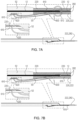
- the stent assembly 101 can be seen to be in a 'dual-stent stent-advancement configuration' in which the guidewire 12 first passes through the distal and proximal apertures 320, 262 so as to interiorly traverse the guidewire-retaining segment 222, the first stent 52 is arranged to surround a stent-conveyance tube segment that is proximally displaced from the guidewire-retaining segment 222, the guidewire 12 is further passed through aperture 400 between the two stents 52, 54 so as to interiorly traverse the portion of the tube 220 that is proximal thereto, and the second stent is arranged to surround a second stent-conveyance tube segment that is proximally displaced from the first stent 52 and from aperture 400.
- the dual-stent stent-advancement configuration is suitable for advancement of the first and second stents 52, 54 together with the stent-con
- the method additionally comprises:
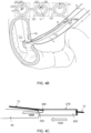
- Steps of the instant method for deploying multiple biliary stents in a lumen of a human body will be explained in greater detail in connection with Figs. 6A-E .
- Fig. 6A shows the positions of first and second stents 52, 54 after Step S04 and before Step S07.
- Stent 52 is deployed in the lumen 4, and guidewire 12 is disengaged from the stent-conveyance tube 220.
- the second stent 54 can be seen as mounted on the tube segment proximal to aperture 400.
- tube 220 can be advanced distally in the direction indicated by arrow A4.
- An example of such a locking mechanism is described hereinbelow with reference to Figs. 8A-8D .
- the fixed distance is at least 5 mm, and for some applications, the fixed distance is no more than less than 25mm.
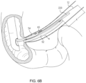
- the second stent 54 is shown (as indicted by arrow A5) as having advanced over stent-conveyance tube 220 and over guidewire 12 as well, while Step S07 is carried out.
- the distal end of second stent 54 has advanced distally from aperture 400, which can no longer be seen in Fig. 6B .
- the guidewire 12 is maintained within lumen 4 and is not advanced proximally or distally in the lumen 4, at least not for purposes of carrying out the instant method.
- a pusher tube 60 can be used to facilitate the distal advancement of the second stent 54 along the stent-conveyance tube, and/or to facilitate 'pushing' the second stent 54 off the distal end of the tube 220 when the tube 220 is proximally withdrawn in Step S08.
- Step S08 is illustrated in Figs. 6D-6E .
- the stent-conveyance tube 220 can be seen to have been withdrawn from within the second stent 54, now anchored in the lumen.
- Fig. 6E it can be seen that the guidewire 12 has been withdrawn as well.
- Steps S01 .. S04 employing the first method (Steps S01 .. S04) of deploying a single stent, three times (once for each stent), aided by the same guidewire each time, the guide wire remaining in place after at least the first and second stents have been deployed; and employing said first method of deploying a single stent, the guidewire remaining in place thereafter, and subsequently employing the method of deploying two stents (Steps S01 .. S08).
- Figs. 7A-7B and 8A-8D are schematic illustrations of locking mechanisms configured to prevent motion of first stent 52 and, optionally, second stent 54, with respect to the guide tube.
- the locking mechanisms are typically employed in order to allow stents to be advanced together with the guide tube in a controlled manner within the lumen of the subject. Once the physician removes each locking mechanism, the respective stent can be deployed off the distal end of the guide tube in the lumen.
- the specific design example described hereinbelow is meant to be illustrative and not limiting.
- the description generally relates to embodiments in which two stents 52, 54 are employed together for deployment according to the method described hereinabove with respect to Steps S01 .. S08, but is equally applicable, with necessary modifications, to the single-stent configurations and methods described hereinabove.
- First lock 600 for preventing proximal and distal motion of first stent 52 with respect to tube 220, as illustrated in Figs. 7A, 7B , 8A and 8D .
- First lock 600 is configured to prevent proximal motion of the first stent 52 past a location that is at least 1- 80 mm (e.g., 2-80 mm, e.g., 5-80 mm, e.g., 5-mm) distal to the distal end of second stent 54 if present.
- 1- 80 mm e.g., 2-80 mm, e.g., 5-80 mm, e.g., 5-mm
- first locking wire 610 proximally, thereby releasing the locking of first stent 52 by disengaging locking wire 610 from locking loop 620. This disengaging allows proximal motion of the tube 220, whereby first stent 52 is deployed distally off guide tube 220, e.g., in Step S04 of Fig. 3 or Fig. 5 .
- second locking wire 640 continues to run distally along the inner surface of second stent 54, outside of the tube 220.
- first lock 600 is not arranged to utilize guidewire 12 to prevent distal, or proximal motion of first stent 52. It is additionally noted that locking wire 640 is not arranged to utilize guidewire 12 to prevent distal motion of second stent 54.
- the scope of the present invention includes use of stents and stent assemblies in any suitable lumen to deploy multiple stents, tubes, or other apparatus in the lumen.
- techniques and apparatus described herein may be used in a urethra, and/or in a ureter, and/or in a pancreatic duct, and/or in an esophagus, and/or in a trachea of the subject. Additionally, or alternatively, techniques and apparatus described herein may be used to deploy two or more prostatic stents.
- the first and second stents are delivered to the lumen of the subject without removing the guide tube or a guidewire used during the procedure from the body of the subject following deployment of the first stent and prior to deploying the second stent.
- the first and second stents are both premounted onto the guide tube and advanced into the subject's body in one advancement procedure, to be deployed subsequently within the lumen of the subject, as described herein.
Landscapes
- Health & Medical Sciences (AREA)
- Engineering & Computer Science (AREA)
- Biomedical Technology (AREA)
- Cardiology (AREA)
- Oral & Maxillofacial Surgery (AREA)
- Transplantation (AREA)
- Heart & Thoracic Surgery (AREA)
- Vascular Medicine (AREA)
- Life Sciences & Earth Sciences (AREA)
- Animal Behavior & Ethology (AREA)
- General Health & Medical Sciences (AREA)
- Public Health (AREA)
- Veterinary Medicine (AREA)
- Media Introduction/Drainage Providing Device (AREA)
Claims (14)
- Vorrichtung zur Verwendung mit einem Führungsdraht (12), umfassend:a. einen biliären Stent (52); undb. einen länglichen Stentförderschlauch (220), der ein distales Führungsdrahthaltesegment (222) umfasst, das (i) jeweilige distale und proximale Öffnungen (320, 262), die einen Führungsdrahtweg dort hindurch definieren, und (ii) einen längs seitlich durchbrechbaren Abschnitt (278) beinhaltet,wobei der Stent (52) und der Stentförderschlauch (220) in Kombination mit dem Führungsdraht (12) in einer Stentvorschubkonfiguration für Vorschub des Stents (52) zusammen mit dem Stentförderschlauch (220) entlang des Führungsdrahts (12) in ein Körperlumen (4) eines menschlichen Subjekts anordbar sind, wobei die Stentvorschubkonfiguration derart ist, dass:i. der Führungsdraht (12) durch die jeweiligen Öffnungen (320, 262) verläuft, um das Führungsdrahthaltesegment (222) innen zu durchqueren,ii. der Stent (52) ein Stentförderschlauchsegment umgibt, das proximal von dem Führungsdrahthaltesegment (222) versetzt ist, undiii. der seitlich durchbrechbare Abschnitt (278) des Führungsdrahthaltesegments (222) durch den Führungsdraht (12) als Reaktion auf einen Rückzug des Stentförderschlauchs (220) in proximaler Richtung durchbrechbar ist, um den Führungsdraht (12) von dem Schlauch (220) ohne Längsverschiebung des Führungsdrahts (12) zu entkoppeln, wenn der Stent (52) an einer Zieleinsatzstelle innerhalb des Lumens (4) vorgesehen ist.
- Vorrichtung nach Anspruch 1, wobei in der Stentvorschubkonfiguration der Stent (52) der einzige Stent ist, der mit dem Führungsdraht (12) in Eingriff ist.
- Vorrichtung nach einem der Ansprüche 1-2, wobei die Vorrichtung nur einen einzelnen Stent umfasst, welcher der biliäre Stent (52) ist.
- Vorrichtung nach einem der Ansprüche 1-3, bereitgestellt als eine zusammengesetzte Konfiguration, sodass (i) der einzelne biliäre Stent (52) an dem Stentförderschlauch (220) montiert ist; und (ii) kein anderer Stent als der einzelne biliäre Stent (52) mit dem Stentförderschlauch (220) in Eingriff ist.
- Vorrichtung nach Anspruch 4, ferner umfassend den Führungsdraht (12), der mit dem einzelnen biliären Stent (52) in Eingriff und in Kontakt ist.
- Vorrichtung nach einem der Ansprüche 4-5, wobei sowohl der einzelne biliäre Stent (52) als auch der Stentförderschlauch (220), der daran montiert ist, innerhalb eines gemeinsamen Behälters vorgesehen sind, wobei der Behälter geschlossen ist.
- Vorrichtung nach Anspruch 6, wobei kein anderer Stent als der biliäre Stent (52) innerhalb des gemeinsamen Behälters vorhanden ist.
- Vorrichtung nach Anspruch 3, bereitgestellt in einer Kit-Form, sodass der einzelne biliäre Stent (52) nicht an dem Stentförderschlauch (220) montiert ist, wobei sowohl der einzelne biliäre Stent (52) als auch der Stentförderschlauch (220) beide innerhalb eines gemeinsamen und geschlossenen Behälters vorgesehen sind und kein anderer Stent innerhalb des Behälters vorgesehen ist.
- Vorrichtung nach einem der Ansprüche 6-8, wobei der gemeinsame Behälter ein Beutel ist.
- Vorrichtung nach Anspruch 1, bereitgestellt in einer Kit-Form, sodass der Stentförderschlauch (220) innerhalb eines geschlossenen Behälters vorgesehen ist, ohne dass ein Stent daran montiert ist, wobei ein Inneres des geschlossenen Behälters steril oder sterilisiert ist.
- Vorrichtung nach einem vorhergehenden Anspruch, wobei ein Rückzug des Stentförderschlauchs (220) in proximaler Richtung, der wirksam ist, um zu veranlassen, dass der Führungsdraht (12) den seitlich durchbrechbaren Abschnitt (278) des Führungsdrahthaltesegments (222) durchbricht, durch Anwenden einer ersten proximalen Rückzugskraft von zumindest 100 Gramm und nicht mehr als 20 kg oder zumindest 500 Gramm und nicht mehr als 10 kg oder zumindest 1 kg und nicht mehr als 5 kg oder zumindest 1,5 kg und nicht mehr als 2,5 kg bewirkt werden kann.
- Vorrichtung nach Anspruch 11, wobei ein Rückzug des Stentförderschlauchs (220) in proximaler Richtung nach dem seitlichen Durchbrechen des seitlich durchbrechbaren Abschnittes (278) des Führungsdrahthaltesegments (222) durch den Führungsdraht (12) durch eine zweite proximale Rückzugskraft, die geringer als die erste proximale Rückzugskraft ist, bewirkt werden kann.
- Vorrichtung nach einem der vorhergehenden Ansprüche, wobei der Rückzug des Stentförderschlauchs (220) in proximaler Richtung wirksam ist, um den Stent (52), der in dem Lumen (4) eingesetzt ist, ohne Manipulation des Führungsdrahts (12) zu lassen.
- Vorrichtung nach einem der vorhergehenden Ansprüche, wobei der seitlich durchbrechbare Abschnitt (278) des Führungsdrahthaltesegments (222) zumindest eines von Folgendem beinhaltet: (i) einen Schlitz (280) mit gegenüberliegenden Schlitzlippen (282) und (ii) eine Perforation und (iii) eine verdünnte Schlauchwand (284).
Priority Applications (5)
| Application Number | Priority Date | Filing Date | Title |
|---|---|---|---|
| EP25186483.1A EP4649924A2 (de) | 2018-06-28 | 2020-01-01 | Verfahren und anordnungen zum einsetzen von gallenstents |
| GB2020932.6A GB2594123B (en) | 2020-01-01 | 2020-12-31 | Methods and assemblies for deploying biliary stents |
| DE102021100034.3A DE102021100034A1 (de) | 2020-01-01 | 2021-01-04 | Verfahren und Anordnungen zum Einsatz von Gallenstents |
| IE20210004A IE20210004A2 (en) | 2020-01-01 | 2021-01-04 | Methods and assemblies for deploying biliary stents |
| CN202110004759.7A CN113057775A (zh) | 2020-01-01 | 2021-01-04 | 用于部署胆道支架的方法和组件 |
Applications Claiming Priority (2)
| Application Number | Priority Date | Filing Date | Title |
|---|---|---|---|
| US201862691329P | 2018-06-28 | 2018-06-28 | |
| PCT/IL2019/050713 WO2020003316A1 (en) | 2018-06-28 | 2019-06-27 | Deployment of multiple biliary stents |
Related Child Applications (1)
| Application Number | Title | Priority Date | Filing Date |
|---|---|---|---|
| EP25186483.1A Division EP4649924A2 (de) | 2018-06-28 | 2020-01-01 | Verfahren und anordnungen zum einsetzen von gallenstents |
Publications (3)
| Publication Number | Publication Date |
|---|---|
| EP3756628A1 EP3756628A1 (de) | 2020-12-30 |
| EP3756628B1 true EP3756628B1 (de) | 2025-07-02 |
| EP3756628C0 EP3756628C0 (de) | 2025-07-02 |
Family
ID=67470448
Family Applications (2)
| Application Number | Title | Priority Date | Filing Date |
|---|---|---|---|
| EP20150001.4A Active EP3756628B1 (de) | 2018-06-28 | 2020-01-01 | Anordnungen zum einsetzen von biliären stents |
| EP25186483.1A Pending EP4649924A2 (de) | 2018-06-28 | 2020-01-01 | Verfahren und anordnungen zum einsetzen von gallenstents |
Family Applications After (1)
| Application Number | Title | Priority Date | Filing Date |
|---|---|---|---|
| EP25186483.1A Pending EP4649924A2 (de) | 2018-06-28 | 2020-01-01 | Verfahren und anordnungen zum einsetzen von gallenstents |
Country Status (3)
| Country | Link |
|---|---|
| EP (2) | EP3756628B1 (de) |
| CN (1) | CN112334096B (de) |
| WO (1) | WO2020003316A1 (de) |
Families Citing this family (3)
| Publication number | Priority date | Publication date | Assignee | Title |
|---|---|---|---|---|
| US12186217B2 (en) | 2015-12-22 | 2025-01-07 | Endo Gi Medical Ltd. | Deployment of multiple biliary stents |
| US11744694B2 (en) | 2020-01-01 | 2023-09-05 | Endo Gi Medical Ltd. | Methods and assemblies for deploying biliary stents |
| US20250099729A1 (en) | 2023-09-22 | 2025-03-27 | JMT Medical, Inc. | Devices And Methods for Bile Duct Surgery |
Family Cites Families (8)
| Publication number | Priority date | Publication date | Assignee | Title |
|---|---|---|---|---|
| US8211087B2 (en) * | 2003-07-31 | 2012-07-03 | Cook Medical Technologies Llc | Distal wire stop |
| US9510962B2 (en) * | 2006-06-16 | 2016-12-06 | Olympus Corporation | Stent delivery system |
| US7963987B2 (en) * | 2007-12-28 | 2011-06-21 | Cook Medical Technologies Llc | Sequential implant delivery system |
| GB0810749D0 (en) * | 2008-06-11 | 2008-07-16 | Angiomed Ag | Catherter delivery device |
| CN106456879B (zh) * | 2014-05-02 | 2020-06-30 | 巴德阿克塞斯系统股份有限公司 | 包括导丝和导管控制元件的导管放置装置 |
| US9877832B2 (en) * | 2014-08-22 | 2018-01-30 | Medtronic Vascular, Inc. | Rapid exchange transcatheter valve delivery system |
| US10849773B2 (en) * | 2014-11-10 | 2020-12-01 | Cook Medical Technologies Llc | Stent delivery device |
| GB201522683D0 (en) * | 2015-12-22 | 2016-02-03 | Endogi Ltd | Deployment of multiple biliary stents |
-
2019
- 2019-06-27 CN CN201980042971.3A patent/CN112334096B/zh active Active
- 2019-06-27 WO PCT/IL2019/050713 patent/WO2020003316A1/en not_active Ceased
-
2020
- 2020-01-01 EP EP20150001.4A patent/EP3756628B1/de active Active
- 2020-01-01 EP EP25186483.1A patent/EP4649924A2/de active Pending
Also Published As
| Publication number | Publication date |
|---|---|
| WO2020003316A1 (en) | 2020-01-02 |
| EP4649924A2 (de) | 2025-11-19 |
| CN112334096A (zh) | 2021-02-05 |
| CN112334096B (zh) | 2025-08-26 |
| EP3756628A1 (de) | 2020-12-30 |
| EP3756628C0 (de) | 2025-07-02 |
Similar Documents
| Publication | Publication Date | Title |
|---|---|---|
| AU2020250291B2 (en) | Methods and assemblies for deploying a biliary stent | |
| US11744694B2 (en) | Methods and assemblies for deploying biliary stents | |
| EP3756628B1 (de) | Anordnungen zum einsetzen von biliären stents | |
| US20240024138A1 (en) | Methods and assemblies for deploying biliary stents | |
| US10729454B2 (en) | Guidewire capture | |
| JP5347175B2 (ja) | 導入器 | |
| IE20210234A1 (en) | Stent-deployment assemblies with locking mechanisms and methods of assembly | |
| EP2693991B1 (de) | System zur verabreichung von endoprothesen | |
| US20200306065A1 (en) | Systems and methods for deploying a luminal prosthesis over a carina | |
| US20110054495A1 (en) | Device for delivering a clip within a patient | |
| EP3393406B1 (de) | Einsatz mehrerer gallenstents | |
| EP3494936A1 (de) | Endografteinführungsvorrichtungsanordnung | |
| US12186217B2 (en) | Deployment of multiple biliary stents | |
| US20230346582A1 (en) | Stent-deployment assemblies with locking mechanisms and methods of assembly | |
| US20250127640A1 (en) | Deployment of multiple biliary stents | |
| EP3251634B1 (de) | Einführeranordnung für medizinische vorrichtung, insbesondere für verzweigte medizinische vorrichtungen | |
| US20190060620A1 (en) | Integrated stent and delivery system | |
| EP3069695B1 (de) | Endografteinführeranordnung mit einer transferhülle | |
| HK1188552B (en) | Endoprosthesis delivery system | |
| HK1188552A (en) | Endoprosthesis delivery system |
Legal Events
| Date | Code | Title | Description |
|---|---|---|---|
| PUAI | Public reference made under article 153(3) epc to a published international application that has entered the european phase |
Free format text: ORIGINAL CODE: 0009012 |
|
| STAA | Information on the status of an ep patent application or granted ep patent |
Free format text: STATUS: THE APPLICATION HAS BEEN PUBLISHED |
|
| AK | Designated contracting states |
Kind code of ref document: A1 Designated state(s): AL AT BE BG CH CY CZ DE DK EE ES FI FR GB GR HR HU IE IS IT LI LT LU LV MC MK MT NL NO PL PT RO RS SE SI SK SM TR |
|
| AX | Request for extension of the european patent |
Extension state: BA ME |
|
| STAA | Information on the status of an ep patent application or granted ep patent |
Free format text: STATUS: REQUEST FOR EXAMINATION WAS MADE |
|
| 17P | Request for examination filed |
Effective date: 20210629 |
|
| RBV | Designated contracting states (corrected) |
Designated state(s): AL AT BE BG CH CY CZ DE DK EE ES FI FR GB GR HR HU IE IS IT LI LT LU LV MC MK MT NL NO PL PT RO RS SE SI SK SM TR |
|
| GRAP | Despatch of communication of intention to grant a patent |
Free format text: ORIGINAL CODE: EPIDOSNIGR1 |
|
| STAA | Information on the status of an ep patent application or granted ep patent |
Free format text: STATUS: GRANT OF PATENT IS INTENDED |
|
| INTG | Intention to grant announced |
Effective date: 20240916 |
|
| GRAJ | Information related to disapproval of communication of intention to grant by the applicant or resumption of examination proceedings by the epo deleted |
Free format text: ORIGINAL CODE: EPIDOSDIGR1 |
|
| STAA | Information on the status of an ep patent application or granted ep patent |
Free format text: STATUS: REQUEST FOR EXAMINATION WAS MADE |
|
| GRAS | Grant fee paid |
Free format text: ORIGINAL CODE: EPIDOSNIGR3 |
|
| STAA | Information on the status of an ep patent application or granted ep patent |
Free format text: STATUS: GRANT OF PATENT IS INTENDED |
|
| GRAP | Despatch of communication of intention to grant a patent |
Free format text: ORIGINAL CODE: EPIDOSNIGR1 |
|
| INTC | Intention to grant announced (deleted) | ||
| INTG | Intention to grant announced |
Effective date: 20250128 |
|
| GRAA | (expected) grant |
Free format text: ORIGINAL CODE: 0009210 |
|
| STAA | Information on the status of an ep patent application or granted ep patent |
Free format text: STATUS: THE PATENT HAS BEEN GRANTED |
|
| AK | Designated contracting states |
Kind code of ref document: B1 Designated state(s): AL AT BE BG CH CY CZ DE DK EE ES FI FR GB GR HR HU IE IS IT LI LT LU LV MC MK MT NL NO PL PT RO RS SE SI SK SM TR |
|
| REG | Reference to a national code |
Ref country code: GB Ref legal event code: FG4D |
|
| REG | Reference to a national code |
Ref country code: CH Ref legal event code: EP |
|
| REG | Reference to a national code |
Ref country code: DE Ref legal event code: R096 Ref document number: 602020053619 Country of ref document: DE |
|
| REG | Reference to a national code |
Ref country code: IE Ref legal event code: FG4D |
|
| U01 | Request for unitary effect filed |
Effective date: 20250801 |
|
| U07 | Unitary effect registered |
Designated state(s): AT BE BG DE DK EE FI FR IT LT LU LV MT NL PT RO SE SI Effective date: 20250812 |
|
| REG | Reference to a national code |
Ref country code: ES Ref legal event code: FG2A Ref document number: 3042250 Country of ref document: ES Kind code of ref document: T3 Effective date: 20251119 |
|
| PG25 | Lapsed in a contracting state [announced via postgrant information from national office to epo] |
Ref country code: IS Free format text: LAPSE BECAUSE OF FAILURE TO SUBMIT A TRANSLATION OF THE DESCRIPTION OR TO PAY THE FEE WITHIN THE PRESCRIBED TIME-LIMIT Effective date: 20251102 |
|
| PG25 | Lapsed in a contracting state [announced via postgrant information from national office to epo] |
Ref country code: NO Free format text: LAPSE BECAUSE OF FAILURE TO SUBMIT A TRANSLATION OF THE DESCRIPTION OR TO PAY THE FEE WITHIN THE PRESCRIBED TIME-LIMIT Effective date: 20251002 |
|
| PG25 | Lapsed in a contracting state [announced via postgrant information from national office to epo] |
Ref country code: HR Free format text: LAPSE BECAUSE OF FAILURE TO SUBMIT A TRANSLATION OF THE DESCRIPTION OR TO PAY THE FEE WITHIN THE PRESCRIBED TIME-LIMIT Effective date: 20250702 |
|
| PG25 | Lapsed in a contracting state [announced via postgrant information from national office to epo] |
Ref country code: GR Free format text: LAPSE BECAUSE OF FAILURE TO SUBMIT A TRANSLATION OF THE DESCRIPTION OR TO PAY THE FEE WITHIN THE PRESCRIBED TIME-LIMIT Effective date: 20251003 |
|
| PG25 | Lapsed in a contracting state [announced via postgrant information from national office to epo] |
Ref country code: CZ Free format text: LAPSE BECAUSE OF FAILURE TO SUBMIT A TRANSLATION OF THE DESCRIPTION OR TO PAY THE FEE WITHIN THE PRESCRIBED TIME-LIMIT Effective date: 20250702 |
|
| PG25 | Lapsed in a contracting state [announced via postgrant information from national office to epo] |
Ref country code: PL Free format text: LAPSE BECAUSE OF FAILURE TO SUBMIT A TRANSLATION OF THE DESCRIPTION OR TO PAY THE FEE WITHIN THE PRESCRIBED TIME-LIMIT Effective date: 20250702 |
|
| PG25 | Lapsed in a contracting state [announced via postgrant information from national office to epo] |
Ref country code: RS Free format text: LAPSE BECAUSE OF FAILURE TO SUBMIT A TRANSLATION OF THE DESCRIPTION OR TO PAY THE FEE WITHIN THE PRESCRIBED TIME-LIMIT Effective date: 20251002 |