EP3755980B1 - Überwachung von partikeltemperaturtrends - Google Patents
Überwachung von partikeltemperaturtrends Download PDFInfo
- Publication number
- EP3755980B1 EP3755980B1 EP19701333.7A EP19701333A EP3755980B1 EP 3755980 B1 EP3755980 B1 EP 3755980B1 EP 19701333 A EP19701333 A EP 19701333A EP 3755980 B1 EP3755980 B1 EP 3755980B1
- Authority
- EP
- European Patent Office
- Prior art keywords
- particles
- sensor arrangement
- temperature
- sensing elements
- view
- Prior art date
- Legal status (The legal status is an assumption and is not a legal conclusion. Google has not performed a legal analysis and makes no representation as to the accuracy of the status listed.)
- Active
Links
Images


Classifications
-
- G—PHYSICS
- G01—MEASURING; TESTING
- G01J—MEASUREMENT OF INTENSITY, VELOCITY, SPECTRAL CONTENT, POLARISATION, PHASE OR PULSE CHARACTERISTICS OF INFRARED, VISIBLE OR ULTRAVIOLET LIGHT; COLORIMETRY; RADIATION PYROMETRY
- G01J5/00—Radiation pyrometry, e.g. infrared or optical thermometry
- G01J5/0066—Radiation pyrometry, e.g. infrared or optical thermometry for hot spots detection
-
- A—HUMAN NECESSITIES
- A62—LIFE-SAVING; FIRE-FIGHTING
- A62C—FIRE-FIGHTING
- A62C3/00—Fire prevention, containment or extinguishing specially adapted for particular objects or places
- A62C3/04—Fire prevention, containment or extinguishing specially adapted for particular objects or places for dust or loosely-baled or loosely-piled materials, e.g. in silos, in chimneys
-
- G—PHYSICS
- G01—MEASURING; TESTING
- G01J—MEASUREMENT OF INTENSITY, VELOCITY, SPECTRAL CONTENT, POLARISATION, PHASE OR PULSE CHARACTERISTICS OF INFRARED, VISIBLE OR ULTRAVIOLET LIGHT; COLORIMETRY; RADIATION PYROMETRY
- G01J5/00—Radiation pyrometry, e.g. infrared or optical thermometry
- G01J5/0014—Radiation pyrometry, e.g. infrared or optical thermometry for sensing the radiation from gases, flames
-
- G—PHYSICS
- G01—MEASURING; TESTING
- G01J—MEASUREMENT OF INTENSITY, VELOCITY, SPECTRAL CONTENT, POLARISATION, PHASE OR PULSE CHARACTERISTICS OF INFRARED, VISIBLE OR ULTRAVIOLET LIGHT; COLORIMETRY; RADIATION PYROMETRY
- G01J5/00—Radiation pyrometry, e.g. infrared or optical thermometry
- G01J5/0022—Radiation pyrometry, e.g. infrared or optical thermometry for sensing the radiation of moving bodies
-
- G—PHYSICS
- G08—SIGNALLING
- G08B—SIGNALLING OR CALLING SYSTEMS; ORDER TELEGRAPHS; ALARM SYSTEMS
- G08B17/00—Fire alarms; Alarms responsive to explosion
- G08B17/12—Actuation by presence of radiation or particles, e.g. of infrared radiation or of ions
Definitions
- the present disclosure relates generally to systems and methods for monitoring of temperature trends for particles moving along a path of movement from a first position to a second position.
- Masses of particles may be moved around in different types of production facilities, such as e.g. process plants, e.g. in connection with the pneumatic transport of particles.
- the material is often loosely formed and transported by a gas or in a gas or gaseous mixture, such as air, in which the material particles are mutually discrete.
- the material particles may e.g. be extremely fine, dust-like particles, powdery material, granular particles, wood chips, pellets or straw.
- the process plants may e.g. be recycling plants, sawmills, or different types of production plants, for e.g. various types of food, diapers, pulp or paper.
- Particles may before or during such transport become so heated that they will form hot particles, glowing embers or sparks, which may initiate fire or explosion in a risk zone. If burning or glowing particles can be detected, the risk area can be isolated, or firefighting or choking means can be supplied, prior to the initiation of a fire or explosion.
- US3824392 describes a transducer that may be used to detect burning or glowing particles in connection with the transport of particles.
- the transducer has at least two mutually separated sensing zones, in which light-sensitive sensing elements co-operating with each zone receive light during the movement of a light-emitting particle, such as a spark or a fire flake, through the field-of-view of the transducer.
- the signal sent from the transducer when a light-emitting particle passes the transducer will thus be in the form of a pulse train. This eliminates false alarms due to light changes caused by e.g. the switching on of lamps.
- the process may be interrupted, or fire eliminating means may be supplied.
- US5740867 describes a preventive safety system which can be applied in a process in which loosely formed material is produced in a first unit and transported, through an indicating zone and an extinguishing zone, to a second unit. If a hazardous high-temperature particle is detected in the indicating zone, an extinguishing agent may e.g. be delivered in the extinguishing zone.
- US5749420 describes a preventive safety system which can be applied in a process in which loosely formed material is produced in a first unit and transported to a second unit, and in which the sensed intensity is used to calculate the liability of a particle to initiate fire and/or explosion.
- the risk level in a system transporting particles depends on both the temperature and the energy content of the particles.
- Prior art systems determine this risk level by measuring the signal strength for a detector that captures heat generated radiation. The signal strength for such a detector depends on both the temperature and the energy content of the particle. In prior art systems, this signal strength is compared to a threshold, giving the general output "high risk” or "low risk", based on whether the signal strength is above or below the threshold.
- the first and second sensing elements are arranged in first and second sensors, which first and second sensors are arranged beside each other and/or in parallel along the path of movement of the particles. This is a straight-forward way of creating a sensor arrangement.
- sensing elements from more than one set of sensing elements are arranged to co-operate with the same sensing zone. There may e.g. be one sensing element from each set of sensing elements co-operating with each sensing zone.
- the temperature of particles moving through the field-of-view of the sensor arrangement may be determined. It may also be determined how close the temperature of the particles moving through the field-of-view of the sensor arrangement is to the ignition temperature for the particle type of the particles moving along the path of movement from the first position to the second position.
- the rate of change in the temperature of particles moving through the field-of-view of the sensor arrangement may be determined. This may e.g. be used to determine if the temperature increases rapidly.
- information about temperature trends for the particles moving through the field-of-view of the sensor arrangement may be sent to at least one operator, and/or to a control system.
- alerts or information type "alarms” to be sent in case of e.g. increasing temperatures, so that corrective action can be taken before the temperature of the particles has reached the level where the system generates a "real" alarm.
- the analysis of temperature trends also enables an optimization of the monitored process.
- changes over time in the energy content of the particles moving through the field-of-view of the sensor arrangement are also monitored. If the temperature of the particles is close or to or above the ignition temperature for the specific type of particle, a rise in energy content may indicate imminent danger.
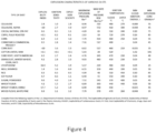
- FIG 4 is a table showing the explosion characteristics of dusts of different particle types.
- the ignition temperature for powdered sugar in cloud form is 370°C, while the ignition temperature for fully roasted coffee in cloud form is 720°C.
- the ignition temperatures of rice in cloud form (510°C) and cotton linter in cloud form (520°C) are rather similar, while the ignition energies are quite different (0,1 J for rice and 1,92J for cotton linter).
- the prior art way of determining the risk level based on the signal strength of a detector that generally captures heat generated radiation may thus either give false alarms for cotton linter or fail to warn when the temperature of rice becomes dangerously high, even though the ignition temperatures are the same.
- a sensor arrangement that can detect temperature differences.
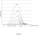
- One option is of course to use a regular temperature sensor. However, it is important that it is really the temperature of the moving particles that is determined. Since an easy way of differentiating radiation emitted from the moving particles from ambient radiation is to use a sensor arrangement comprising a set of at least two sensing elements arranged to co-operate with mutually separated sensing zones along the path of movement of the particles, as described in US3824392 , a number of such sets of sensing elements, each set comprising sensing elements which detect radiation of wavelengths within a certain wavelength range, may be used to monitor the temperature of the particles. The relation between the signal strengths of signals detected by the sets of sensing elements will determine the temperature, since a body at a certain temperature emits radiation with a certain wavelength distribution, based on Planck's Law of Radiation.
- Figure 5 illustrates the optical radiation over different temperatures for a typical particle. It can be seen in figure 5 that if the relation between the signal strengths from the different sets of sensing elements, each of which detect radiation of wavelengths within a certain wavelength range, is e.g. linear, with the signal strength increasing slightly at longer wavelengths, the temperature is relatively low. If instead the signal strength e.g. has a peak at a certain wavelength, and decreases at higher wavelengths, the temperature is high.
- the analysis of temperature trends enables alerts or information type "alarms" to be sent to operators of the system, and/or to a control system, in case of e.g. increasing temperatures, so that corrective action can be taken before the temperature of the particles has reached the level where the system generates a "real" alarm.
- the analysis of temperature trends also enables an optimization of the monitored process.
- the present disclosure relates generally to systems and methods for monitoring of temperature trends for particles moving along a path of movement from a first position to a second position.
- the movement of the particles along the path of movement from the first position to the second position may be effected in many different ways, such as using pneumatic transport (suction or blow), pressing, or simply letting the particles fall using gravity (if there is a vertical difference between the first position and the second position).
- pneumatic transport suction or blow
- pressing or simply letting the particles fall using gravity (if there is a vertical difference between the first position and the second position).
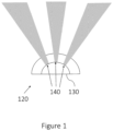
- FIG. 1 schematically illustrates a sensor arrangement 120, in accordance with one or more embodiments described herein.
- the sensor arrangement 120 shown in figure 1 comprises three mutually separated sensing zones, and a set of three sensing elements 140 detecting radiation emitted from the particles 160, each arranged to co-operate with one of the sensing zones.
- FIG. 2 schematically illustrates a sensor arrangement 120, in accordance with one or more embodiments described herein.
- Each set of sensing elements 140 in the sensor arrangement 120 may be arranged in a sensor 130, and the sensor arrangement 120 may comprise any number of sensors 130, each of which detecting radiation of wavelengths within a certain wavelength range.
- Each of the three sensors 130 shown in figure 2 comprises a set of three sensing elements 140, where the three sensing elements 140 of each set are arranged to co-operate with three mutually separated sensing zones along the path 150 of movement of the particles 160.
- the sensor arrangement 120 may be arranged to detect a signal related to the temperature of particles 160 moving in front of it and through its field-of-view, preferably with a sensing angle of up to 180 degrees.
- the at least one processing device 180 may be arranged to receive signals from each sensor 130 and form the signals from each set of sensing elements 140 into a pulse train.
- FIG. 3 schematically illustrates a system 100 for monitoring of temperature trends for particles 160 moving along a path 150 of movement from a first position to a second position, in accordance with one or more embodiments described herein.
- the system 100 comprises a sensor arrangement 120, a field-of-view of which is arranged in the path 150 of movement of particles 160 moving through said field-of-view, and at least one processing device 180.
- the sensor arrangement 120 may be arranged to detect a signal related to the temperature of particles 160 moving in front of it and through its field-of-view.
- the sensor arrangement 120 shown in figure 3 comprises at least one set of sensing elements 140, each set comprising three sensing elements 140 arranged to co-operate with three mutually separated sensing zones along the path 150 of movement of the particles 160.
- the sensor arrangement 120 shown in figures 1-3 is arranged in a path 150 of movement of the particles 160, but the sensor arrangement 120 may also, or alternatively, be arranged next to a path 150 of movement of the particles 160, as long as the field-of-view of the sensor arrangement 120 is arranged in a path 150 of movement of the particles 160.
- the path 150 of movement is in figure 1-3 shown as being horizontal, but it may have any orientation. If the particles 160 are intended to fall pass the sensor arrangement 120 using gravity, a vertical orientation may be preferred.
- the sensing elements 140 are preferably sensing elements that have a clear temperature dependent response in a temperature range covering the ignition temperatures of the particles 160 moving along a path 150 of movement from a first position to a second position.
- Such sensing elements are e.g. lead sulphide cells, which are preferably used to detect radiation in wavelengths between 1 and 3 ⁇ m.
- the shape of the temperature curve is significantly different for different temperatures in this wavelength range, in a temperature range covering the ignition temperatures of many common particles, as listed in the table of figure 4 .
- the at least one processing device 180 may be arranged to receive signals from the sensor arrangement 120 and form the signals from the at least one set of sensing elements 140 into at least one pulse train. Based on this at least one pulse train, the at least one processing device 180 may then monitor changes over time in the temperature of particles 160 moving through the field-of-view of the sensor arrangement 120, preferably by monitoring changes over time in the wavelength distribution of the radiation emitted from the particles 160.
- the at least one processing device 180 may further be arranged to determine a relation between the signal strengths of signals detected by different sets of sensing elements 140 or by the same sets of sensing elements 140 using different wavelength filters.
- the sensor arrangement 120 shown in figure 1 comprises one sensor 130 comprising three mutually separated sensing zones along the path 150 of movement of the particles 160, and three sensing elements 140, each co-operating with one of the sensing zones.
- An easy way of accurately monitoring of temperature trends for particles 160 moving along a path 150 of movement from a first position to a second position is to include several sets of sensing elements 140, each set comprising sensing elements 140 that detect radiation of wavelengths within a certain wavelength range, in the sensor arrangement 120.
- Such several sets of sensing elements 140 may be arranged in only one sensor 130, or in a number of different sensors 130.
- the radiation wavelengths that the sensing elements 140 are sensitive to may depend on e.g. the material of the sensing elements 140.
- An alternative way of accurately monitoring of temperature trends for particles 160 moving along a path 150 of movement from a first position to a second position is to use several different wavelength filters, each wavelength filter causing the sensing elements 140 to detect radiation of wavelengths within a certain wavelength range, in the sensor arrangement 120.
- the at least one processing device 180 may be arranged to determine a relation between the signal strengths of the signals detected by the different sets of sensing elements 140 or through the different wavelength filters, and based on this relation monitor changes over time in the temperature of particles 160 moving through the field-of-view of the sensor arrangement 120.
- Figure 2 shows three sets of sensing elements 140, each set arranged in a sensor 130.
- the three sensors 130 shown in figure 2 are arranged beside each other along the path 150 of movement of the particles 160, which means that a particle 160 will pass one sensor 130 after the other.
- the signals from the sensors 130 i.e. the sets of sensing elements 140
- the signals from the sets of sensing elements 140 may e.g. be correlated based on the phase shift.
- the sensor arrangement 120 will output an average value for the particles 160. In such a case the exact phase shift may be less important.
- the sensors 130 are instead arranged in parallel along the path 150 of movement of the particles 160, so that a particle 160 passes all sensors 130, i.e. all sets of sensing elements 140, simultaneously. Combinations are also possible, so that groups of sensing elements 140 arranged in parallel are arranged beside each other along the path 150 of movement of the particles 160. It is e.g. possible to arrange a number of different sensing elements 140 in each sensing zone, so that the sensor arrangement 120 comprises at least two mutually separated sensing zones, where in each sensing zone a number of different sensing elements 140, each of which detecting radiation of wavelengths within a certain wavelength range, are arranged. Sensing elements 140 from more than one set of sensing elements may thus be arranged to co-operate with the same sensing zone. There may e.g. be a sensing element 140 from each set of sensing elements co-operating with each sensing zone.
- the temperature of the particles 160 moving through the field-of-view of the sensor arrangement 120 may also be determined. This enables at least one processing device 180 to determine how close the temperature of the particles 160 is to the ignition temperature for the particle type of the particles moving along the path 150 of movement from the first position to the second position, and thus enables a very accurate determination of the risk level.
- the risk is low even if the energy content of the particles 160 would be very high, but if the temperature of the particles 160 is above the ignition temperature for the particle type of the particles moving along the path 150 of movement from the first position to the second position, even relatively low energy content may become dangerous.
- the type of a particle 160 is a way of describing different inherent aspects of the particle.
- the particle type depends on the material of the particle 160, but also on e.g. the size of the particle 160.
- Wood chips are e.g. considered to belong to a different particle type than sawdust, even though the wood chips may come from the same type of wood as the sawdust.
- various treatments to the particles 160 way affect the particle type.
- Fully roasted coffee is e.g. considered as a different particle type than plain coffee beans.
- Various coverings on the particles 160 may affect both the ignition temperature and the ignition energy.
- not all particles 160 are of the same particle type.
- other particle types may also be transported, usually in the form of pollutions or contaminations.
- hot metal flakes may have been sheared from process equipment during a process stage before the transport of the particles 160. Since it is especially the risk that such metal flakes ignite the surrounding particles 160 that needs to be avoided, the temperature of the metal flakes should be compared with the ignition temperature of the surrounding particles, not with the ignition temperature of the metal in question.
- the at least one processing device 180 may be arranged to determine the rate of change in the temperature of particles 160 moving through the field-of-view of the sensor arrangement 120. Slow temperature changes may e.g. be caused by overloads in the monitored process. This does not necessarily increase the risk of a fire or explosion, but the information about such overloads may e.g. be used to optimize the monitored process.
- the rate of change in the temperature of particles 160 moving through the field-of-view of the sensor arrangement 120 is above a predetermined threshold, the rate of change may be determined to be fast. This may e.g. be caused by pollutions or contaminations in the system, and thus alarms should preferably be sent in such situations.
- Information about temperature trends of particles 160 moving through the field-of-view of the sensor arrangement 120 may thus be sent to at least one operator, and/or to a control system.
- This information may e.g. be sent as alarms, information type "alarms", alerts, instructions to set flags in the control system, or plain data.
- the average temperature of the particles 160 moving through the field-of-view of the sensor arrangement 120 may fluctuate, e.g. depending on the type of processing the particles 160 have been subjected to, or the amount of particles 160. A certain fluctuation may be normal, and therefore it may be desirable to adapt the temperature threshold to the average temperature of the particles 160, provided that this stays within a predefined acceptable level of fluctuation. If the fluctuation is greater than the predefined acceptable level of fluctuation, information may be sent to the at least one operator, and/or to the control system.
- the predefined acceptable level of fluctuation may e.g. depend on the type of processing the particles 160 have been subjected to. For example, when monitoring a processing plant for the making of particle boards, the monitoring of the average temperature of the sawdust particles may reveal information about the process of sawing the particle boards. The average temperature of the sawdust particles will increase as soon as the saw starts sawing trough the particle board, but in a normal situation return to the average temperature before the sawing, once the particle board has been sawed through. If the average temperature instead increases over time, for each sawing through the particle board, this may e.g. be an indication that the extraction of sawdust from the saw is not working properly, e.g. due to the pipe being clogged.
- the average temperature increases during the sawing through the particle board, this may e.g. be an indication that the saw blade is becoming blunt.
- Information about how the average temperature of the particles 160 fluctuates may therefore be used to optimize the process, by e.g. exchanging saw blades when the monitoring reveals that they are becoming blunt.
- Figure 6 schematically illustrates a method 600 for monitoring of temperature trends for particles 160 moving along a path 150 of movement from a first position to a second position, in accordance with one or more embodiments described herein.
- the method 600 may comprise: Step 610: detecting a signal related to the temperature of particles 160 moving through a field-of-view of a sensor arrangement 120, said field-of-view being arranged in the path 150 of movement of the particles 160, the sensor arrangement 120 comprising at least one set of sensing elements 140 detecting radiation emitted from the particles 160, each set comprising at least two sensing elements 140 arranged to co-operate with mutually separated sensing zones along the path 150 of movement of the particles 160.
- Step 620 forming the signals from the at least one set of sensing elements 140 into at least one pulse train when a particle 160 moves through the field-of-view of the sensor arrangement 120.
- Step 630 monitoring changes over time in the temperature of particles 160 moving through the field-of-view of the sensor arrangement 120 based on this at least one pulse train by monitoring changes over time in the wavelength distribution of the radiation emitted from the particles 160.
- Use of the method 600 allows for an accurate monitoring of the temperature of particles 160 moving along a path 150 of movement from a first position to a second position
- the sensor arrangement 120 may comprise first and second sets of sensing elements 140, wherein the first set of sensing elements 140 detects radiation of wavelengths within a first wavelength range, and the second set of sensing elements 140 detects radiation of wavelengths within a second wavelength range, wherein the second wavelength range differs from the first wavelength range.
- the monitoring 630 may further comprise determining a relation between the signal strengths of the signals detected by the first and second sets of sensing elements 140, and based on this relation monitoring changes over time in the wavelength distribution of the radiation emitted from the particles 160.
- the first and second sets of sensing elements 140 may be arranged in first and second sensors 130, which first and second sensors 130 are arranged beside each other and/or in parallel along the path 150 of movement of the particles 160.
- Sensing elements from more than one set of sensing elements 140 may be arranged to co-operate with the same sensing zone.
- the sensor arrangement 120 may also, or alternatively, comprise first and second wavelength filter arrangements, wherein the first wavelength filter arrangement causes the sensor arrangement 120 to detect radiation of wavelengths within a first wavelength range, and the second wavelength filter arrangement causes the sensor arrangement 120 to detect radiation of wavelengths within a second wavelength range, wherein the second wavelength range differs from the first wavelength range.
- the monitoring 630 may further comprise determining a relation between the signal strengths of the signals detected by the sensor arrangement 120 through the first and second wavelength filter arrangements, and based on this relation monitor changes over time in the wavelength distribution of the radiation emitted from the particles 160.
- the method 600 may further comprise one or more of the following steps: Step 640: determining the temperature of particles 160 moving through the field-of-view of the sensor arrangement 120.
- Step 650 determining how close the temperature of the particles 160 moving through the field-of-view of the sensor arrangement 120 is to the ignition temperature for the particle type.
- Step 660 determining the rate of change in the temperature of particles 160 moving through the field-of-view of the sensor arrangement 120.
- Step 670 determining whether the temperature of the particles 160 moving through the field-of-view of the sensor arrangement 120 has changed more than a predetermined threshold amount.
- Step 680 sending information about temperature trends for the particles 160 moving through the field-of-view of the sensor arrangement 120 to at least one operator, and/or to a control system.
- Step 690 monitoring changes over time also in the energy content of the particles 160 moving through the field-of-view of the sensor arrangement 120.
- the sensing elements 140 may be any type of sensing elements that are able to individually detect radiation - any number of sensing elements 140 may e.g. be arranged on the same substrate. In a radiation sensor divided into pixels, a sensing element may e.g. be a group of pixels, or even a single pixel. Accordingly, the scope of the invention is defined only by the claims.
Landscapes
- Physics & Mathematics (AREA)
- General Physics & Mathematics (AREA)
- Spectroscopy & Molecular Physics (AREA)
- Business, Economics & Management (AREA)
- Emergency Management (AREA)
- Health & Medical Sciences (AREA)
- Public Health (AREA)
- Radiation Pyrometers (AREA)
- Measuring And Recording Apparatus For Diagnosis (AREA)
Claims (14)
- System (100) zur Überwachung von Temperaturtrends für Partikel (160), die sich entlang eines Bewegungspfades (150) von einer ersten Position zu einer zweiten Position bewegen, wobei das System (100) Folgendes umfasst:eine Sensoranordnung (120), deren Sichtfeld im Bewegungspfad (150) der Partikel (160) angeordnet ist, um ein Signal zu erfassen, das mit der Temperatur der sich durch das Sichtfeld bewegenden Partikel (160) in Beziehung steht, wobei die Sensoranordnung (120) mindestens einen Satz von Sensorelementen (140) umfasst, die von den Partikeln (160) emittierte Strahlung erfassen, wobei jeder Satz mindestens zwei Sensorelemente (140) umfasst, die angeordnet sind, um mit voneinander getrennten Sensorzonen entlang des Bewegungspfades (150) der Partikel (160) zusammenzuwirken; undmindestens eine Verarbeitungsvorrichtung (180), die dazu eingerichtet ist:Signale von der Sensoranordnung (120) zu empfangen;Signale von dem mindestens einen Satz von Sensorelementen (140) in mindestens eine Impulsfolge zu bilden, wenn sich ein Partikel (160) durch das Sichtfeld der Sensoranordnung (120) bewegt; undauf der Grundlage dieser mindestens einen Impulsfolge zeitliche Änderungen der Temperatur von Partikeln (160) zu überwachen, die sich durch das Sichtfeld der Sensoranordnung (120) bewegen, indem zeitliche Änderungen der Wellenlängenverteilung der von den Partikeln (160) emittierten Strahlung überwacht werden,
wobei die Sensoranordnung (120) einen ersten und einen zweiten Satz von Sensorelementen (140) umfasst, wobei der erste Satz von Sensorelementen (140) Strahlung mit Wellenlängen innerhalb eines ersten Wellenlängenbereichs erfasst, und der zweite Satz von Sensorelementen (140) Strahlung mit Wellenlängen innerhalb eines zweiten Wellenlängenbereichs erfasst, wobei sich der zweite Wellenlängenbereich von dem ersten Wellenlängenbereich unterscheidet, dadurch gekennzeichnet, dassdie mindestens eine Verarbeitungsvorrichtung (180) eingerichtet ist, eine Beziehung zwischen den Signalstärken der von den ersten und zweiten Sätzen von Sensorelementen (140) erfassten Signale zu bestimmen, und auf der Grundlage dieser Beziehung zeitliche Veränderungen in der Wellenlängenverteilung der von den Partikeln (160) emittierten Strahlung zu überwachen. - System (100) zur Überwachung von Temperaturtrends für Partikel (160), die sich entlang eines Bewegungspfades (150) von einer ersten Position zu einer zweiten Position bewegen, wobei das System (100) Folgendes umfasst:eine Sensoranordnung (120), deren Sichtfeld in dem Bewegungspfad (150) der Partikel (160) angeordnet ist, um ein Signal zu erfassen, das mit der Temperatur der sich durch das Sichtfeld bewegenden Partikel (160) in Beziehung steht, wobei die Sensoranordnung (120) mindestens einen Satz von Sensorelementen (140) umfasst, die von den Partikeln (160) emittierte Strahlung detektieren, wobei jeder Satz mindestens zwei Sensorelemente (140) umfasst, die angeordnet sind, um mit voneinander getrennten Sensorzonen entlang des Bewegungspfads (150) der Partikel (160) zusammenzuwirken; undmindestens eine Verarbeitungsvorrichtung (180), die dazu eingerichtet ist:Signale von der Sensoranordnung (120) zu empfangen;Signale von dem mindestens einen Satz von Sensorelementen (140) in mindestens eine Impulsfolge zu bilden, wenn sich ein Partikel (160) durch das Sichtfeld der Sensoranordnung (120) bewegt; undauf der Grundlage dieser mindestens einen Impulsfolge zeitliche Änderungen der Temperatur von Partikeln (160) zu überwachen, die sich durch das Sichtfeld der Sensoranordnung (120) bewegen, indem zeitliche Änderungen der Wellenlängenverteilung der von den Partikeln (160) emittierten Strahlung überwacht werden,wobei die Sensoranordnung (120) eine erste und eine zweite Wellenlängenfilteranordnung umfasst, wobei die erste Wellenlängenfilteranordnung die Sensoranordnung (120) veranlasst, Strahlung von Wellenlängen innerhalb eines ersten Wellenlängenbereichs zu erfassen, und die zweite Wellenlängenfilteranordnung die Sensoranordnung (120) veranlasst, Strahlung von Wellenlängen innerhalb eines zweiten Wellenlängenbereichs zu erfassen,wobei sich der zweite Wellenlängenbereich von dem ersten Wellenlängenbereich unterscheidet, dadurch gekennzeichnet, dass
die mindestens eine Verarbeitungsvorrichtung (180) eingerichtet ist, eine Beziehung zwischen den Signalstärken der von der Sensoranordnung (120) durch die erste und zweite Wellenlängenfilteranordnung erfassten Signale zu bestimmen, und auf der Grundlage dieser Beziehung zeitliche Veränderungen in der Wellenlängenverteilung der von den Partikeln (160) emittierten Strahlung zu überwachen. - System (100) nach Anspruch 1 oder 2, wobei der erste und der zweite Satz von Sensorelementen (140) in einem ersten und einem zweiten Sensor (130) angeordnet sind, wobei der erste und der zweite Sensor (130) nebeneinander und/oder parallel entlang des Bewegungspfads (150) der Partikel (160) angeordnet sind.
- System (100) nach einem der Ansprüche 1-3, wobei Sensorelemente aus mehr als einem Satz von Sensorelementen (140) angeordnet sind, um mit demselben Fühlerbereich zusammenzuwirken.
- System (100) nach einem der Ansprüche 1-4, wobei die mindestens eine Verarbeitungsvorrichtung (180) weiter dazu eingerichtet ist, die Temperatur von Partikeln (160) zu bestimmen, die sich durch das Sichtfeld der Sensoranordnung (120) bewegen.
- System (100) nach Anspruch 5, wobei die mindestens eine Verarbeitungsvorrichtung (180) eingerichtet ist, um zu bestimmen, wie nahe die Temperatur der Partikel (160), die sich durch das Sichtfeld der Sensoranordnung (120) bewegen, an der Zündtemperatur für den Partikeltyp der Partikel liegt, die sich entlang des Bewegungspfads (150) von der ersten Position zur zweiten Position bewegen.
- Verfahren (600) zur Überwachung von Temperaturtrends für Partikel (160), die sich entlang eines Bewegungspfades (150) von einer ersten Position zu einer zweiten Position bewegen, wobei das Verfahren (600) Folgendes umfasst:Erfassen (610) eines Signals, das mit der Temperatur von Partikeln (160) in Beziehung steht, die sich durch ein Sichtfeld einer Sensoranordnung (120) bewegen, wobei das Sichtfeld in dem Bewegungspfad (150) der Partikel (160) angeordnet ist, wobei die Sensoranordnung (120) mindestens einen Satz von Sensorelementen (140) umfasst, die von den Partikeln (160) emittierte Strahlung erfassen, wobei jeder Satz mindestens zwei Sensorelemente (140) umfasst, die angeordnet sind, um mit voneinander getrennten Sensorzonen entlang des Bewegungspfades (150) der Partikel (160) zusammenzuwirken;Bilden (620) der Signale von dem mindestens einen Satz von Sensorelementen (140) in mindestens eine Impulsfolge, wenn sich ein Partikel (160) durch das Sichtfeld der Sensoranordnung (120) bewegt; undÜberwachen (630) von zeitlichen Änderungen der Temperatur von Partikeln (160), die sich durch das Sichtfeld der Sensoranordnung (120) bewegen, durch Überwachen von zeitlichen Änderungen der Wellenlängenverteilung der von den Partikeln (160) emittierten Strahlung auf der Grundlage dieser mindestens einen Impulsfolge, wobei die Sensoranordnung (120) einen ersten und einen zweiten Satz von Sensorelementen (140) umfasst, wobei der erste Satz von Sensorelementen (140) Strahlung mit Wellenlängen innerhalb eines ersten Wellenlängenbereichs erfasst, und der zweite Satz von Sensorelementen (140) Strahlung mit Wellenlängen innerhalb eines zweiten Wellenlängenbereichs erfasst, wobei sich der zweite Wellenlängenbereich von dem ersten Wellenlängenbereich unterscheidet, dadurch gekennzeichnet, dass die Überwachung (630) weiter die Bestimmung einer Beziehung zwischen den Signalstärken der von den ersten und zweiten Sätzen von Sensorelementen (140) erfassten Signale und auf der Grundlage dieser Beziehung die Überwachung von Änderungen der Wellenlängenverteilung der von den Partikeln (160) emittierten Strahlung im Laufe der Zeit umfasst.
- Verfahren (600) zur Überwachung von Temperaturtrends für Partikel (160), die sich entlang eines Bewegungspfades (150) von einer ersten Position zu einer zweiten Position bewegen, wobei das Verfahren (600) Folgendes umfasst:Erfassen (610) eines Signals, das mit der Temperatur von Partikeln (160) in Beziehung steht, die sich durch ein Sichtfeld einer Sensoranordnung (120) bewegen, wobei das Sichtfeld in dem Bewegungspfad (150) der Partikel (160) angeordnet ist, wobei die Sensoranordnung (120) mindestens einen Satz von Sensorelementen (140) umfasst, die von den Partikeln (160) emittierte Strahlung detektieren, wobei jeder Satz mindestens zwei Sensorelemente (140) umfasst, die angeordnet sind, um mit voneinander getrennten Sensorzonen entlang des Bewegungspfads (150) der Partikel (160) zusammenzuwirken;Bilden (620) der Signale von dem mindestens einen Satz von Sensorelementen (140) in mindestens eine Impulsfolge, wenn sich ein Partikel (160) durch das Sichtfeld der Sensoranordnung (120) bewegt; undÜberwachen (630) von zeitlichen Änderungen der Temperatur von Partikeln (160), die sich durch das Sichtfeld der Sensoranordnung (120) bewegen, durch Überwachen von zeitlichen Änderungen der Wellenlängenverteilung der von den Partikeln (160) emittierten Strahlung auf der Grundlage dieser mindestens einen Impulsfolge, wobei die Sensoranordnung (120) eine erste und eine zweite Filteranordnung umfasst,wobei die erste Filteranordnung die Sensoranordnung (120) veranlasst, Strahlung von Wellenlängen innerhalb eines ersten Wellenlängenbereichs zu erfassen, und die zweite Filteranordnung die Sensoranordnung (120) veranlasst, Strahlung von Wellenlängen innerhalb eines zweiten Wellenlängenbereichs zu erfassen,wobei sich der zweite Wellenlängenbereich von dem ersten Wellenlängenbereich unterscheidet, dadurch gekennzeichnet, dass
das Überwachen (630) weiter das Bestimmen einer Beziehung zwischen den Signalstärken der von der Sensoranordnung (120) durch die erste und zweite Filteranordnung erfassten Signale und auf der Grundlage dieser Beziehung das Überwachen von Änderungen in der Wellenlängenverteilung der von den Partikeln (160) emittierten Strahlung über die Zeit umfasst. - Verfahren (600) nach Anspruch 7 oder 8, weiter umfassend das Bestimmen (640) der Temperatur von Partikeln (160), die sich durch das Sichtfeld der Sensoranordnung (120) bewegen.
- Verfahren (600) nach Anspruch 9, weiter umfassend das Bestimmen (650), wie nahe die Temperatur der Partikel (160), die sich durch das Sichtfeld der Sensoranordnung (120) bewegen, an der Zündtemperatur für den Partikeltyp der Partikel ist, die sich entlang des Bewegungspfads (150) von der ersten Position zur zweiten Position bewegen.
- Verfahren (600) nach einem der Ansprüche 7-10, weiter umfassend das Bestimmen (660) der Änderungsrate der Temperatur von Partikeln (160), die sich durch das Sichtfeld der Sensoranordnung (120) bewegen.
- Verfahren (600) nach einem der Ansprüche 7-11, weiter umfassend das Bestimmen (670), ob sich die Temperatur der Partikel (160), die sich durch das Sichtfeld der Sensoranordnung (120) bewegen, um mehr als einen vorbestimmten Schwellenwert geändert hat.
- Verfahren (600) nach einem der Ansprüche 7-12, weiter umfassend das Senden (680) von Informationen über Temperaturtrends für die Partikel (160), die sich durch das Sichtfeld der Sensoranordnung (120) bewegen, an mindestens einen Bediener und/oder an ein Steuerungssystem.
- Verfahren (600) nach einem der Ansprüche 7-13, weiter umfassend das Überwachen (690) von zeitlichen Änderungen auch des Energiegehalts der sich durch das Sichtfeld der Sensoranordnung (120) bewegenden Partikel (160).
Applications Claiming Priority (2)
| Application Number | Priority Date | Filing Date | Title |
|---|---|---|---|
| SE1850207A SE541656C2 (en) | 2018-02-23 | 2018-02-23 | Monitoring of particle temperature trends |
| PCT/EP2019/051378 WO2019162011A1 (en) | 2018-02-23 | 2019-01-21 | Monitoring of particle temperature trends |
Publications (2)
| Publication Number | Publication Date |
|---|---|
| EP3755980A1 EP3755980A1 (de) | 2020-12-30 |
| EP3755980B1 true EP3755980B1 (de) | 2024-09-11 |
Family
ID=65199416
Family Applications (1)
| Application Number | Title | Priority Date | Filing Date |
|---|---|---|---|
| EP19701333.7A Active EP3755980B1 (de) | 2018-02-23 | 2019-01-21 | Überwachung von partikeltemperaturtrends |
Country Status (5)
| Country | Link |
|---|---|
| US (1) | US11927486B2 (de) |
| EP (1) | EP3755980B1 (de) |
| CN (1) | CN111656149B (de) |
| SE (1) | SE541656C2 (de) |
| WO (1) | WO2019162011A1 (de) |
Family Cites Families (11)
| Publication number | Priority date | Publication date | Assignee | Title |
|---|---|---|---|---|
| SE364588B (de) * | 1972-04-24 | 1974-02-25 | Pak Construction Ab | |
| US4142417A (en) * | 1978-04-28 | 1979-03-06 | The United States Of America As Represented By The Secretary Of The Interior | Multichannel infrared pyrometer |
| SE455471B (sv) * | 1985-11-29 | 1988-07-18 | Firefly Ab | Anordning for att forhindra risk for brand pa grund av brinnande eller glodande partiklar i en rorledning |
| SE501122C2 (sv) | 1993-10-08 | 1994-11-21 | Firefly Ab | Preventivt skyddssystem |
| SE9303306L (sv) | 1993-10-08 | 1994-11-21 | Firefly Ab | Detektorarrangemang |
| SE515579C2 (sv) * | 1998-12-29 | 2001-09-03 | Firefly Ab | Detektorarrangemang för att detektera partiklar som kan orsaka brand eller explosion i en partikelström |
| EP2126570A1 (de) * | 2006-06-06 | 2009-12-02 | Vivacta Limited | Verfahren zur messung einer chemikalie |
| US7843352B2 (en) * | 2007-02-13 | 2010-11-30 | B&S Safety Systems, Inc. | Ignition-source detecting system and associated methods |
| US8405033B2 (en) | 2010-07-30 | 2013-03-26 | Buglab Llc | Optical sensor for rapid determination of particulate concentration |
| ITUB20155886A1 (it) * | 2015-11-25 | 2017-05-25 | A M General Contractor S P A | Rilevatore d?incendio a radiazione infrarossa con funzione composta per ambiente confinato. |
| CN107204093A (zh) * | 2017-05-22 | 2017-09-26 | 上海热像机电科技股份有限公司 | 一种确定触发警情位置的方法及系统 |
-
2018
- 2018-02-23 SE SE1850207A patent/SE541656C2/en unknown
-
2019
- 2019-01-21 EP EP19701333.7A patent/EP3755980B1/de active Active
- 2019-01-21 WO PCT/EP2019/051378 patent/WO2019162011A1/en not_active Ceased
- 2019-01-21 CN CN201980010550.2A patent/CN111656149B/zh active Active
- 2019-01-21 US US16/971,578 patent/US11927486B2/en active Active
Also Published As
| Publication number | Publication date |
|---|---|
| CN111656149A (zh) | 2020-09-11 |
| SE1850207A1 (en) | 2019-08-24 |
| CN111656149B (zh) | 2023-09-15 |
| WO2019162011A1 (en) | 2019-08-29 |
| US11927486B2 (en) | 2024-03-12 |
| US20200386622A1 (en) | 2020-12-10 |
| EP3755980A1 (de) | 2020-12-30 |
| SE541656C2 (en) | 2019-11-19 |
Similar Documents
| Publication | Publication Date | Title |
|---|---|---|
| AU2016322778B2 (en) | System and method for detecting smoldering in processes with continuous air flow | |
| US8791826B2 (en) | Method and device for fire detection in enclosed environments | |
| KR900002655B1 (ko) | 석탄미분쇄기의 안전제어시스템 | |
| WO2014181082A1 (en) | Improvements in and relating to aspirating smoke detectors | |
| EP0244074B1 (de) | Sicherheitssysteme für Kohlenpulverisiermühlen | |
| EP3755980B1 (de) | Überwachung von partikeltemperaturtrends | |
| US4653698A (en) | Safety system for coal pulverizers | |
| US11976978B2 (en) | Determination of risk level for particles | |
| US4778113A (en) | Apparatus for monitoring low level combustibles | |
| CN113617505B (zh) | 一种中速磨煤机内部爆燃预警系统和方法 | |
| CN107449702A (zh) | 一种基于粉尘爆炸条件的车间安全预警方法 | |
| EP2091029B1 (de) | Gefahrenerkennung mit Einbezug einer in einem Mikrocontroller integrierten Temperaturmesseinrichtung | |
| JP3568205B2 (ja) | 安全システム | |
| EP1147502B1 (de) | Detektierungsverfahren für glühende teilchen | |
| JP2004099264A (ja) | コンベア火災検知装置及びそれを有するコンベア | |
| Sweis | Dust explosions in the food industries | |
| SU960877A1 (ru) | Способ обнаружени возгораний | |
| JPS604140B2 (ja) | 発火防止方法 | |
| JPS6029798B2 (ja) | 可燃性繊維の風送路における異常感知作動装置 |
Legal Events
| Date | Code | Title | Description |
|---|---|---|---|
| STAA | Information on the status of an ep patent application or granted ep patent |
Free format text: STATUS: UNKNOWN |
|
| STAA | Information on the status of an ep patent application or granted ep patent |
Free format text: STATUS: THE INTERNATIONAL PUBLICATION HAS BEEN MADE |
|
| PUAI | Public reference made under article 153(3) epc to a published international application that has entered the european phase |
Free format text: ORIGINAL CODE: 0009012 |
|
| STAA | Information on the status of an ep patent application or granted ep patent |
Free format text: STATUS: REQUEST FOR EXAMINATION WAS MADE |
|
| 17P | Request for examination filed |
Effective date: 20200831 |
|
| AK | Designated contracting states |
Kind code of ref document: A1 Designated state(s): AL AT BE BG CH CY CZ DE DK EE ES FI FR GB GR HR HU IE IS IT LI LT LU LV MC MK MT NL NO PL PT RO RS SE SI SK SM TR |
|
| AX | Request for extension of the european patent |
Extension state: BA ME |
|
| DAV | Request for validation of the european patent (deleted) | ||
| DAX | Request for extension of the european patent (deleted) | ||
| STAA | Information on the status of an ep patent application or granted ep patent |
Free format text: STATUS: EXAMINATION IS IN PROGRESS |
|
| 17Q | First examination report despatched |
Effective date: 20221121 |
|
| GRAP | Despatch of communication of intention to grant a patent |
Free format text: ORIGINAL CODE: EPIDOSNIGR1 |
|
| STAA | Information on the status of an ep patent application or granted ep patent |
Free format text: STATUS: GRANT OF PATENT IS INTENDED |
|
| INTG | Intention to grant announced |
Effective date: 20240412 |
|
| GRAS | Grant fee paid |
Free format text: ORIGINAL CODE: EPIDOSNIGR3 |
|
| GRAA | (expected) grant |
Free format text: ORIGINAL CODE: 0009210 |
|
| STAA | Information on the status of an ep patent application or granted ep patent |
Free format text: STATUS: THE PATENT HAS BEEN GRANTED |
|
| AK | Designated contracting states |
Kind code of ref document: B1 Designated state(s): AL AT BE BG CH CY CZ DE DK EE ES FI FR GB GR HR HU IE IS IT LI LT LU LV MC MK MT NL NO PL PT RO RS SE SI SK SM TR |
|
| REG | Reference to a national code |
Ref country code: GB Ref legal event code: FG4D |
|
| REG | Reference to a national code |
Ref country code: CH Ref legal event code: EP |
|
| REG | Reference to a national code |
Ref country code: DE Ref legal event code: R096 Ref document number: 602019058646 Country of ref document: DE |
|
| REG | Reference to a national code |
Ref country code: IE Ref legal event code: FG4D |
|
| REG | Reference to a national code |
Ref country code: SE Ref legal event code: TRGR |
|
| REG | Reference to a national code |
Ref country code: LT Ref legal event code: MG9D |
|
| PG25 | Lapsed in a contracting state [announced via postgrant information from national office to epo] |
Ref country code: NO Free format text: LAPSE BECAUSE OF FAILURE TO SUBMIT A TRANSLATION OF THE DESCRIPTION OR TO PAY THE FEE WITHIN THE PRESCRIBED TIME-LIMIT Effective date: 20241211 |
|
| REG | Reference to a national code |
Ref country code: NL Ref legal event code: MP Effective date: 20240911 |
|
| PG25 | Lapsed in a contracting state [announced via postgrant information from national office to epo] |
Ref country code: GR Free format text: LAPSE BECAUSE OF FAILURE TO SUBMIT A TRANSLATION OF THE DESCRIPTION OR TO PAY THE FEE WITHIN THE PRESCRIBED TIME-LIMIT Effective date: 20241212 Ref country code: FI Free format text: LAPSE BECAUSE OF FAILURE TO SUBMIT A TRANSLATION OF THE DESCRIPTION OR TO PAY THE FEE WITHIN THE PRESCRIBED TIME-LIMIT Effective date: 20240911 |
|
| PG25 | Lapsed in a contracting state [announced via postgrant information from national office to epo] |
Ref country code: BG Free format text: LAPSE BECAUSE OF FAILURE TO SUBMIT A TRANSLATION OF THE DESCRIPTION OR TO PAY THE FEE WITHIN THE PRESCRIBED TIME-LIMIT Effective date: 20240911 |
|
| PG25 | Lapsed in a contracting state [announced via postgrant information from national office to epo] |
Ref country code: LV Free format text: LAPSE BECAUSE OF FAILURE TO SUBMIT A TRANSLATION OF THE DESCRIPTION OR TO PAY THE FEE WITHIN THE PRESCRIBED TIME-LIMIT Effective date: 20240911 |
|
| PG25 | Lapsed in a contracting state [announced via postgrant information from national office to epo] |
Ref country code: HR Free format text: LAPSE BECAUSE OF FAILURE TO SUBMIT A TRANSLATION OF THE DESCRIPTION OR TO PAY THE FEE WITHIN THE PRESCRIBED TIME-LIMIT Effective date: 20240911 |
|
| PG25 | Lapsed in a contracting state [announced via postgrant information from national office to epo] |
Ref country code: ES Free format text: LAPSE BECAUSE OF FAILURE TO SUBMIT A TRANSLATION OF THE DESCRIPTION OR TO PAY THE FEE WITHIN THE PRESCRIBED TIME-LIMIT Effective date: 20240911 Ref country code: RS Free format text: LAPSE BECAUSE OF FAILURE TO SUBMIT A TRANSLATION OF THE DESCRIPTION OR TO PAY THE FEE WITHIN THE PRESCRIBED TIME-LIMIT Effective date: 20241211 |
|
| PG25 | Lapsed in a contracting state [announced via postgrant information from national office to epo] |
Ref country code: RS Free format text: LAPSE BECAUSE OF FAILURE TO SUBMIT A TRANSLATION OF THE DESCRIPTION OR TO PAY THE FEE WITHIN THE PRESCRIBED TIME-LIMIT Effective date: 20241211 Ref country code: NO Free format text: LAPSE BECAUSE OF FAILURE TO SUBMIT A TRANSLATION OF THE DESCRIPTION OR TO PAY THE FEE WITHIN THE PRESCRIBED TIME-LIMIT Effective date: 20241211 Ref country code: LV Free format text: LAPSE BECAUSE OF FAILURE TO SUBMIT A TRANSLATION OF THE DESCRIPTION OR TO PAY THE FEE WITHIN THE PRESCRIBED TIME-LIMIT Effective date: 20240911 Ref country code: HR Free format text: LAPSE BECAUSE OF FAILURE TO SUBMIT A TRANSLATION OF THE DESCRIPTION OR TO PAY THE FEE WITHIN THE PRESCRIBED TIME-LIMIT Effective date: 20240911 Ref country code: GR Free format text: LAPSE BECAUSE OF FAILURE TO SUBMIT A TRANSLATION OF THE DESCRIPTION OR TO PAY THE FEE WITHIN THE PRESCRIBED TIME-LIMIT Effective date: 20241212 Ref country code: FI Free format text: LAPSE BECAUSE OF FAILURE TO SUBMIT A TRANSLATION OF THE DESCRIPTION OR TO PAY THE FEE WITHIN THE PRESCRIBED TIME-LIMIT Effective date: 20240911 Ref country code: ES Free format text: LAPSE BECAUSE OF FAILURE TO SUBMIT A TRANSLATION OF THE DESCRIPTION OR TO PAY THE FEE WITHIN THE PRESCRIBED TIME-LIMIT Effective date: 20240911 Ref country code: BG Free format text: LAPSE BECAUSE OF FAILURE TO SUBMIT A TRANSLATION OF THE DESCRIPTION OR TO PAY THE FEE WITHIN THE PRESCRIBED TIME-LIMIT Effective date: 20240911 |
|
| REG | Reference to a national code |
Ref country code: AT Ref legal event code: MK05 Ref document number: 1723087 Country of ref document: AT Kind code of ref document: T Effective date: 20240911 |
|
| PG25 | Lapsed in a contracting state [announced via postgrant information from national office to epo] |
Ref country code: NL Free format text: LAPSE BECAUSE OF FAILURE TO SUBMIT A TRANSLATION OF THE DESCRIPTION OR TO PAY THE FEE WITHIN THE PRESCRIBED TIME-LIMIT Effective date: 20240911 |
|
| PG25 | Lapsed in a contracting state [announced via postgrant information from national office to epo] |
Ref country code: PT Free format text: LAPSE BECAUSE OF FAILURE TO SUBMIT A TRANSLATION OF THE DESCRIPTION OR TO PAY THE FEE WITHIN THE PRESCRIBED TIME-LIMIT Effective date: 20250113 Ref country code: IS Free format text: LAPSE BECAUSE OF FAILURE TO SUBMIT A TRANSLATION OF THE DESCRIPTION OR TO PAY THE FEE WITHIN THE PRESCRIBED TIME-LIMIT Effective date: 20250111 |
|
| PGFP | Annual fee paid to national office [announced via postgrant information from national office to epo] |
Ref country code: DE Payment date: 20250110 Year of fee payment: 7 |
|
| PG25 | Lapsed in a contracting state [announced via postgrant information from national office to epo] |
Ref country code: RO Free format text: LAPSE BECAUSE OF FAILURE TO SUBMIT A TRANSLATION OF THE DESCRIPTION OR TO PAY THE FEE WITHIN THE PRESCRIBED TIME-LIMIT Effective date: 20240911 Ref country code: SM Free format text: LAPSE BECAUSE OF FAILURE TO SUBMIT A TRANSLATION OF THE DESCRIPTION OR TO PAY THE FEE WITHIN THE PRESCRIBED TIME-LIMIT Effective date: 20240911 |
|
| PG25 | Lapsed in a contracting state [announced via postgrant information from national office to epo] |
Ref country code: EE Free format text: LAPSE BECAUSE OF FAILURE TO SUBMIT A TRANSLATION OF THE DESCRIPTION OR TO PAY THE FEE WITHIN THE PRESCRIBED TIME-LIMIT Effective date: 20240911 Ref country code: AT Free format text: LAPSE BECAUSE OF FAILURE TO SUBMIT A TRANSLATION OF THE DESCRIPTION OR TO PAY THE FEE WITHIN THE PRESCRIBED TIME-LIMIT Effective date: 20240911 |
|
| PG25 | Lapsed in a contracting state [announced via postgrant information from national office to epo] |
Ref country code: CZ Free format text: LAPSE BECAUSE OF FAILURE TO SUBMIT A TRANSLATION OF THE DESCRIPTION OR TO PAY THE FEE WITHIN THE PRESCRIBED TIME-LIMIT Effective date: 20240911 Ref country code: PL Free format text: LAPSE BECAUSE OF FAILURE TO SUBMIT A TRANSLATION OF THE DESCRIPTION OR TO PAY THE FEE WITHIN THE PRESCRIBED TIME-LIMIT Effective date: 20240911 |
|
| PG25 | Lapsed in a contracting state [announced via postgrant information from national office to epo] |
Ref country code: SK Free format text: LAPSE BECAUSE OF FAILURE TO SUBMIT A TRANSLATION OF THE DESCRIPTION OR TO PAY THE FEE WITHIN THE PRESCRIBED TIME-LIMIT Effective date: 20240911 Ref country code: IT Free format text: LAPSE BECAUSE OF FAILURE TO SUBMIT A TRANSLATION OF THE DESCRIPTION OR TO PAY THE FEE WITHIN THE PRESCRIBED TIME-LIMIT Effective date: 20240911 |
|
| REG | Reference to a national code |
Ref country code: DE Ref legal event code: R097 Ref document number: 602019058646 Country of ref document: DE |
|
| PG25 | Lapsed in a contracting state [announced via postgrant information from national office to epo] |
Ref country code: DK Free format text: LAPSE BECAUSE OF FAILURE TO SUBMIT A TRANSLATION OF THE DESCRIPTION OR TO PAY THE FEE WITHIN THE PRESCRIBED TIME-LIMIT Effective date: 20240911 |
|
| PLBE | No opposition filed within time limit |
Free format text: ORIGINAL CODE: 0009261 |
|
| STAA | Information on the status of an ep patent application or granted ep patent |
Free format text: STATUS: NO OPPOSITION FILED WITHIN TIME LIMIT |
|
| 26N | No opposition filed |
Effective date: 20250612 |
|
| REG | Reference to a national code |
Ref country code: CH Ref legal event code: PL |
|
| PG25 | Lapsed in a contracting state [announced via postgrant information from national office to epo] |
Ref country code: MC Free format text: LAPSE BECAUSE OF FAILURE TO SUBMIT A TRANSLATION OF THE DESCRIPTION OR TO PAY THE FEE WITHIN THE PRESCRIBED TIME-LIMIT Effective date: 20240911 Ref country code: LU Free format text: LAPSE BECAUSE OF NON-PAYMENT OF DUE FEES Effective date: 20250121 |
|
| PG25 | Lapsed in a contracting state [announced via postgrant information from national office to epo] |
Ref country code: BE Free format text: LAPSE BECAUSE OF NON-PAYMENT OF DUE FEES Effective date: 20250131 |
|
| PGFP | Annual fee paid to national office [announced via postgrant information from national office to epo] |
Ref country code: GB Payment date: 20250708 Year of fee payment: 7 |
|
| PGFP | Annual fee paid to national office [announced via postgrant information from national office to epo] |
Ref country code: FR Payment date: 20250721 Year of fee payment: 7 |
|
| PG25 | Lapsed in a contracting state [announced via postgrant information from national office to epo] |
Ref country code: CH Free format text: LAPSE BECAUSE OF NON-PAYMENT OF DUE FEES Effective date: 20250131 |
|
| PGFP | Annual fee paid to national office [announced via postgrant information from national office to epo] |
Ref country code: SE Payment date: 20250709 Year of fee payment: 7 |
|
| REG | Reference to a national code |
Ref country code: BE Ref legal event code: MM Effective date: 20250131 |