EP2091029B1 - Gefahrenerkennung mit Einbezug einer in einem Mikrocontroller integrierten Temperaturmesseinrichtung - Google Patents
Gefahrenerkennung mit Einbezug einer in einem Mikrocontroller integrierten Temperaturmesseinrichtung Download PDFInfo
- Publication number
- EP2091029B1 EP2091029B1 EP08101643A EP08101643A EP2091029B1 EP 2091029 B1 EP2091029 B1 EP 2091029B1 EP 08101643 A EP08101643 A EP 08101643A EP 08101643 A EP08101643 A EP 08101643A EP 2091029 B1 EP2091029 B1 EP 2091029B1
- Authority
- EP
- European Patent Office
- Prior art keywords
- temperature
- microcontroller
- measurement signal
- hazard
- alarm
- Prior art date
- Legal status (The legal status is an assumption and is not a legal conclusion. Google has not performed a legal analysis and makes no representation as to the accuracy of the status listed.)
- Active
Links
- 238000009529 body temperature measurement Methods 0.000 title claims abstract description 32
- 230000003287 optical effect Effects 0.000 claims abstract description 48
- 239000000779 smoke Substances 0.000 claims abstract description 33
- 238000005259 measurement Methods 0.000 claims abstract description 31
- 238000000034 method Methods 0.000 claims abstract description 26
- 230000008859 change Effects 0.000 claims description 6
- 230000001419 dependent effect Effects 0.000 claims description 6
- 238000000053 physical method Methods 0.000 claims 2
- 238000011156 evaluation Methods 0.000 abstract description 15
- 238000012360 testing method Methods 0.000 description 15
- 239000002245 particle Substances 0.000 description 11
- 230000004044 response Effects 0.000 description 10
- 230000008901 benefit Effects 0.000 description 9
- 238000004519 manufacturing process Methods 0.000 description 8
- 239000003570 air Substances 0.000 description 7
- 239000012080 ambient air Substances 0.000 description 6
- 230000035945 sensitivity Effects 0.000 description 6
- 230000008878 coupling Effects 0.000 description 4
- 238000010168 coupling process Methods 0.000 description 4
- 238000005859 coupling reaction Methods 0.000 description 4
- 238000001514 detection method Methods 0.000 description 4
- 238000010586 diagram Methods 0.000 description 4
- 239000007789 gas Substances 0.000 description 4
- 238000000149 argon plasma sintering Methods 0.000 description 3
- 230000006870 function Effects 0.000 description 3
- 230000003595 spectral effect Effects 0.000 description 3
- 230000002123 temporal effect Effects 0.000 description 3
- 239000004020 conductor Substances 0.000 description 2
- 230000000694 effects Effects 0.000 description 2
- 231100001261 hazardous Toxicity 0.000 description 2
- 238000010438 heat treatment Methods 0.000 description 2
- 230000005693 optoelectronics Effects 0.000 description 2
- 239000004065 semiconductor Substances 0.000 description 2
- 239000000443 aerosol Substances 0.000 description 1
- 230000003321 amplification Effects 0.000 description 1
- 238000006243 chemical reaction Methods 0.000 description 1
- 235000019504 cigarettes Nutrition 0.000 description 1
- 239000000567 combustion gas Substances 0.000 description 1
- 238000004590 computer program Methods 0.000 description 1
- 238000010276 construction Methods 0.000 description 1
- 230000006378 damage Effects 0.000 description 1
- 238000013461 design Methods 0.000 description 1
- 238000009429 electrical wiring Methods 0.000 description 1
- 238000005516 engineering process Methods 0.000 description 1
- 230000007613 environmental effect Effects 0.000 description 1
- 230000000977 initiatory effect Effects 0.000 description 1
- 230000001678 irradiating effect Effects 0.000 description 1
- 230000031700 light absorption Effects 0.000 description 1
- 239000000463 material Substances 0.000 description 1
- 238000003199 nucleic acid amplification method Methods 0.000 description 1
- 230000008569 process Effects 0.000 description 1
- 238000012545 processing Methods 0.000 description 1
- 230000006903 response to temperature Effects 0.000 description 1
- 238000000926 separation method Methods 0.000 description 1
- 230000011664 signaling Effects 0.000 description 1
- 229910000679 solder Inorganic materials 0.000 description 1
- 239000000126 substance Substances 0.000 description 1
- 239000000758 substrate Substances 0.000 description 1
- 230000008646 thermal stress Effects 0.000 description 1
Images

Classifications
-
- G—PHYSICS
- G08—SIGNALLING
- G08B—SIGNALLING OR CALLING SYSTEMS; ORDER TELEGRAPHS; ALARM SYSTEMS
- G08B17/00—Fire alarms; Alarms responsive to explosion
- G08B17/06—Electric actuation of the alarm, e.g. using a thermally-operated switch
-
- G—PHYSICS
- G08—SIGNALLING
- G08B—SIGNALLING OR CALLING SYSTEMS; ORDER TELEGRAPHS; ALARM SYSTEMS
- G08B17/00—Fire alarms; Alarms responsive to explosion
- G08B17/10—Actuation by presence of smoke or gases, e.g. automatic alarm devices for analysing flowing fluid materials by the use of optical means
- G08B17/103—Actuation by presence of smoke or gases, e.g. automatic alarm devices for analysing flowing fluid materials by the use of optical means using a light emitting and receiving device
- G08B17/107—Actuation by presence of smoke or gases, e.g. automatic alarm devices for analysing flowing fluid materials by the use of optical means using a light emitting and receiving device for detecting light-scattering due to smoke
-
- G—PHYSICS
- G08—SIGNALLING
- G08B—SIGNALLING OR CALLING SYSTEMS; ORDER TELEGRAPHS; ALARM SYSTEMS
- G08B17/00—Fire alarms; Alarms responsive to explosion
- G08B17/10—Actuation by presence of smoke or gases, e.g. automatic alarm devices for analysing flowing fluid materials by the use of optical means
- G08B17/11—Actuation by presence of smoke or gases, e.g. automatic alarm devices for analysing flowing fluid materials by the use of optical means using an ionisation chamber for detecting smoke or gas
- G08B17/113—Constructional details
-
- G—PHYSICS
- G08—SIGNALLING
- G08B—SIGNALLING OR CALLING SYSTEMS; ORDER TELEGRAPHS; ALARM SYSTEMS
- G08B29/00—Checking or monitoring of signalling or alarm systems; Prevention or correction of operating errors, e.g. preventing unauthorised operation
- G08B29/18—Prevention or correction of operating errors
- G08B29/20—Calibration, including self-calibrating arrangements
- G08B29/24—Self-calibration, e.g. compensating for environmental drift or ageing of components
Definitions
- the present invention relates to the technical field of danger detection technology.
- the present invention relates to a hazard detector which has a primary measuring device for detecting a physical measured variable and for outputting a measuring signal indicative of a predetermined dangerous situation, and a microcontroller, which is connected downstream of the measuring device and which is set up for evaluating the measuring signal.
- the present invention further relates to a method for detecting a dangerous situation.
- the present invention also relates to a computer-readable storage medium and to a program element which contain instructions for carrying out the method according to the invention for detecting a dangerous situation.
- a smoke detector smoke detector in which smoke-scattered light is received by a light-receiving element and a smoke density is detected by using an output level of the light-receiving element.
- the fire detector has a temperature measuring means for measuring the ambient temperature of a Lichtabstrahlimplantations for irradiating the smoke particles and the light receiving element. Further, the fire detector has a temperature compensation means for correcting the output level of the light receiving element in accordance with the ambient temperature measured by the temperature measuring means. It also has smoke density detection means for detecting the smoke density using the output level corrected by the temperature compensation means.
- the temperature compensation means and the smoke density detecting means are realized in the form of a microcomputer.
- Simple optical smoke detectors usually have a light emitting diode in the visible or in the infrared spectral range, which preferably emits light in a scattered range in pulsed form.
- the scattering area is often referred to as a labyrinth. If smoke particles are present in the scattering area, the light beams are at least partially scattered at these and detected by a correspondingly matched light receiver.
- the received optical power of the light receiver Detected measuring light is decisive, if, for example, rather smaller, darker particles, which arise in open fires, or rather larger, lighter particles, which arise in smoldering fires, are detected.
- a "forward scattering" smoke detector is to be understood as a smoke detector in which the angle between the measuring light emitted by the light-emitting diode and the measuring light detected by the light receiver is greater than 90 °, for example approximately 150 °.
- an optical fire detector with only one optical signal path and with an acceptable rate of false alarms usually responds very inhomogeneously to the various test fires.
- TF2 will fire an alarm very early, but the TF5 will fire an alarm very late.
- very early and “very late” always mean a time in relation to the time limits defined in standard 54-7.
- Additional sensor inputs may, for example, be coupled to a temperature sensor.
- the corresponding combination hazard detector is then called the "O-T" hazard alarm.
- O stands for optic and "T” for temperature.
- Such combination detectors are accordingly referred to as "O-O" hazard alarm.
- An "O-T” hazard detector has the disadvantage that its construction is relatively expensive. In fact, the cost of installing a temperature-sensitive component and of the temperature-sensitive component itself is incurred in the production of an "O-T" hazard alarm. In addition, the housing shape of the hazard detector must be adapted to the temperature-sensitive component and mechanical protection measures such as contact protection must be taken.
- the present invention is based on the device-related task of creating a low-cost but nevertheless false alarm-safe hazard alarm.
- the present invention is based on the method-related object to improve the detection of a dangerous situation with regard to a low false alarm rate in a cost-effective manner.
- a danger detector which may in particular be an optical smoke detector.
- the described danger detector has (a) a measuring device for detecting a physical measured variable and for outputting a measuring signal which are indicative of a given dangerous situation, (b) a microcontroller, which is connected downstream of the measuring device and which is set up to evaluate the measuring signal, and (c) a temperature measuring device for detecting a temperature and outputting a temperature measuring signal indicative of the detected temperature.
- the temperature measuring device is integrated in the microcontroller and the microcontroller is set up such that the temperature measurement signal is taken into account in the evaluation of the measurement signal.
- the danger alarm described is based on the finding that modern microprocessors often have integrated temperature-dependent components, which without or only can be used with a small additional apparatus design for a temperature measurement.
- the temperature measurement can be translated, for example by means of an analog / digital converter in a temperature value.
- This temperature value can then represent the housing temperature of the microcontroller.
- the heating of the housing of the microcontroller can be used in addition to the measurement signal of the measuring device as an additional hazard input for an alarm criterion of the danger detector.
- the temperature measuring device is integrated in the microcontroller. This means that a common component housing is provided for the microcontroller and the temperature measuring device. Typically, “integrated” further means that separation of the temperature measuring device from the microcontroller without destruction of at least one of the two components "microcontroller and temperature measuring device" is not possible.
- the sensitivity and response time of the temperature measuring device integrated in the microcontroller will generally not be as good as, for example, a separate temperature-sensitive resistor which is used in a known manner for special temperature detectors.
- Such temperature-sensitive resistors such as NTC resistors (negative temperature coefficient resistors) are in fact arranged spatially in a temperature detector so that they are optimally flowed by the ambient air and respond quickly due to a preferably low thermal mass. Thus, rapid temperature changes can be detected quickly.
- the temperature measuring device integrated in the microcontroller can not completely replace the NTC resistance of a thermal hazard alarm, so that, for example, the thermal standard EN54-5 relevant for danger detectors could not be met.
- One of the integrated temperature measuring device detected increase in the housing temperature of the microcontroller, however, can help to increase in a simple manner and in particular without additional equipment overhead both the sensitivity of the hazard alarm and to reduce the likelihood of triggering a false alarm.
- the temperature measuring signal of the temperature measuring device integrated in the microcontroller is thus used in addition to the measuring signal of the actual measuring device as a further or as an additional alarm signaling input.
- this additional alarm input is thus advantageously no additional apparatusiver effort required in the rule. This applies in any case for such microcontroller, which in any case have a suitable temperature measuring device.
- the measuring device can be, for example, a gas measuring device, which has a chemical sensor to which gas molecules from the ambient air on the sensor surface are chemically bound.
- the bound gas molecules can emit electrical charges which change the electrical conductance of the semiconductor material of the sensor.
- the gases to be detected can be combustion gases such as CO2. From a certain concentration in a monitored room then a danger message or an alarm message is generated by the described danger detector.
- the danger detector can of course also have a plurality of measuring devices, wherein at least one of the measuring devices is combined with the described temperature measuring device with regard to a common signal processing.
- the measurement signals provided by all measuring devices are preferably combined with one another.
- the temperature measuring device is a temperature measuring diode.
- the use of a temperature measuring diode as integrated into the microcontroller temperature measuring device has the advantage that it can be produced without additional process steps in a semiconductor manufacturing of the microcontroller.
- Temperature measuring diodes are already present in many modern microcontrollers anyway. Therefore, the danger detector described can be constructed with simple electronic standard components and thus realized in a cost effective manner.
- the measuring device is an optical measuring device, which has (a) a light transmitter, configured to emit a measuring light, and (b) a light receiver, configured to receive at least a part of the measuring light.
- O-T optical temperature
- the described danger detector works analogously to known so-called O-T (optical temperature) hazard detectors, whereby, however, a commonly used temperature-sensitive resistor is replaced by the temperature measuring device integrated in the microcontroller. This usually reduces the accuracy of the temperature measurement and slows down the time response to temperature changes.
- the temperature measurement signal can still be used for the evaluation of the measurement signal of the primary measuring device and thus contribute to a higher sensitivity and at the same time to a lower false alarm probability compared to hazard detectors with only a single measuring device.
- the described hazard alarm can be made significantly cheaper compared to known O-T hazard detectors.
- the temperature measuring device essentially increases the case temperature of the microcontroller detected. Even if the temperature measuring device is thus inevitably coupled with a comparatively large thermal mass, in the case of a fire the consideration of the rise in the housing temperature can contribute to fulfill the requirement for optical fire detector regulation EN54-7 even with a little sensitive optical balance and therefore the false alarm security significantly increase.
- the light receiver is preferably arranged at an angle of, for example, greater than 10 ° relative to the optical axis of the measurement light emitted by the light emitter. This means that only scattered measurement light reaches the light receiver, which generates a corresponding measurement signal in the presence of smoke particles.
- the light receiver is preferably arranged relative to the light transmitter so that at least a part of unscattered measuring light reaches the light receiver even when no smoke is present. The light intensity measured by the light receiver is in this case reduced by the presence of light-absorbing or even light-scattering smoke particles.
- the described primary optical hazard detector can be calibrated less sensitively compared to a known purely optical hazard alarm.
- This has the advantage that the matching process for the generation or the initiation of a danger message is considerably easier. This is because for more sensitive hazard detectors, the given tolerances are significantly narrower and thus such sensitive hazard detectors are much more difficult to manufacture within the narrow prescribed tolerances of the EN54-7 standard.
- the danger detector additionally has a detector housing in whose spatial center the microcontroller is arranged. This has the advantage that the thermal directional dependence of the described danger detector is low. This, in turn, means that a temperature change caused by a heat source can be detected with a constant sensitivity regardless of the direction in which the heat source is based on the described danger detector.
- the housing has a perfectly symmetrical shape.
- the microcontroller is then preferably arranged at the location within the housing, at which heat sources such as a fire can be detected as independent of direction as possible.
- the danger detector additionally has at least one heat-conducting element, which is connected to a housing of the microcontroller.
- the temperature measuring device of the microcontroller can better detect temperature changes in the air surrounding the danger detector.
- the good heat conducting materials and / or the at least one heat conducting element can be arranged such that they are flowed around or flowed against by the outside air of the hazard alarm.
- the heat-conducting element can also be referred to as a so-called thermal discharge pad.
- the described use of at least one heat conducting element has the advantage that a better thermal coupling the microcontroller to its environment and thus a shorter response time of the microcontroller housing to temperature changes can be ensured.
- the heat element can be used, for example, to thermally couple a shielding plate of the light emitting diode photodiode to the housing of the microcontroller. Since the Ableblleich the photodiode is typically within the air flowed through labyrinth or within the optical measuring chamber of the danger detector, the thermal coupling of the temperature measuring device is improved in a simple and efficient manner to the ambient air, thus effectively reducing the thermal time constant of the housing.
- a method for detecting a dangerous situation in particular for detecting smoke, is specified.
- the specified method comprises (a) detecting a physical measurand and outputting a measurement signal which are indicative of a given hazard situation by means of a measuring device, (b) detecting a temperature and outputting a temperature measuring signal which is indicative of the detected temperature, by means of a temperature measuring device integrated in the microcontroller, and (c) an evaluation of the measuring signal taking into account the temperature measuring signal by means of the microcontroller, which is connected downstream of the measuring device.
- the specified method is based on the finding that simple danger detectors can be upgraded with only one sensor input in a simple manner and in particular without any additional equipment, since a temperature measuring device, which is already present in many modern microcontroller components, for a temperature measurement is used. A temperature measured value achieved thereby is taken into account in the evaluation of the primary measuring signal of the measuring device. Thus, a danger message initiated by the microcontroller no longer depends exclusively on the output primary measuring signal of the measuring device but also on the temperature measuring signal of the temperature measuring device integrated in the microcontroller.
- the method described has the advantage that it can be carried out without any apparatus conversions of many conventional hazard detectors. This also applies to hazard alarms, which initially have only a single alarm input or at least initially no thermal alarm input.
- hazard alarms which initially have only a single alarm input or at least initially no thermal alarm input.
- the only prerequisite for the implementation of the specified method is the presence of a microcontroller having an integrated temperature measuring device.
- the method described can be achieved by simple programming, i. be realized by software.
- the method additionally comprises amplifying the temporal changes of the measurement signal and / or the temperature measurement signal.
- amplifying the temporal changes of the measurement signal and / or the temperature measurement signal This means that, for example, in the case of a temperature increase, the increase in time of the temperature measurement curve detected by the temperature measuring device is increased. In other words, this means that the slope of the temperature measurement curve is increased.
- This can be done in a known manner, for example by a suitable software algorithm and / or by a suitably designed electronic circuit and thus in hardware.
- the described amplification of the temporal changes has the advantage that the temporal response of the integrated temperature measuring device, which is very much slowed down compared to an external NTC, after the Gain at least approximately to the response of an external temperature sensor, such as an NTC, can be approximated.
- only a relative change of the temperature measurement signal is taken into account in the evaluation of the measurement signal by the microcontroller.
- the production of the entire hazard alarm can be as fast as the production of a less powerful conventional hazard alarm, which has only one sensor input and possibly not used in a microcontroller temperature measuring device for the evaluation and initiate a danger message ,
- the temperature measurement signal is indicative of an absolute temperature.
- the consideration of a temperature measurement signal which is indicative of an absolute temperature value, has the advantage that not only temperature changes but also absolute temperature values can be taken into account in the evaluation of the primary measurement signal.
- the danger detector can be adapted even more specifically to specific environmental conditions and, on the one hand, high sensitivity and, on the other hand, a low false alarm probability of the danger detector can be achieved.
- the measuring device is an optical measuring device and the temperature measuring signal is used for a compensation of temperature-dependent effects of the optical measuring device.
- thermal effects within the entire temperature-dependent optical path can be compensated by means of the absolute temperature measurement signal.
- the term optical path is to be understood as meaning not only the entire optical path between the light emitter and the light receiver, but the optical path also includes optical or optoelectronic components, such as the light emitter and the light receiver.
- the optical path also includes optical or optoelectronic components, such as the light emitter and the light receiver.
- temperature changes not only the light output of the light emitter but also the sensitivity of the light receiver can change.
- a set relative adjustment between the light emitter and the light receiver for example, by thermal stresses of holding elements of the danger detector change. All these thermal effects can, insofar as reproducible and known in advance, be taken into account in the evaluation of the primary measurement signal and compensated in a suitable manner.
- the temperature measurement signal essentially reflects the housing temperature of the microcontroller.
- the housing temperature is used for temperature compensation of the optical path. This improves the response the danger detector especially at very cold and very hot temperatures.
- the response of the hazard alarm at 55 degrees may deviate by a maximum of a certain factor from the response at 25 degrees.
- the described compensation of temperature-dependent effects contributes to the fact that the corresponding optical measuring device can more easily fulfill the EN54-7 standard.
- a computer-readable storage medium in which a program for detecting a dangerous situation is stored.
- the program when executed by a microcontroller of a hazard alarm of the type described above, is arranged to perform the above-identified method of detecting a hazardous situation.
- a program element for detecting a dangerous situation is described.
- the program element when executed by a microcontroller of a hazard alarm of the type described above, is arranged to perform the above-identified method for detecting a hazardous situation.
- the program and / or program element may be implemented as a computer-readable instruction code in any suitable programming language such as JAVA, C ++, etc.
- the program and / or the program element can be stored on a computer-readable storage medium (CD-ROM, DVD, removable drive, volatile or non-volatile memory, built-in memory / processor, etc.).
- the instruction code may program a computer or other programmable device to perform the desired functions.
- the program and / or the program element in a network such as the Internet, from which it can be downloaded by a user as needed.
- the invention can be implemented both by means of a computer program, i. software, as well as by means of one or more special electrical circuits, i. in hardware or in any hybrid form, i. using software components and hardware components.
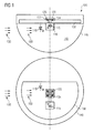
- FIG. 1 shows a schematic representation of a forward scattering, optical hazard detector 100.
- the upper part of FIG. 1 shows the danger detector 100 in a side view parallel to a mounting plane.
- the mounting plane can be, for example, the ceiling of a room to be monitored.
- the lower part of FIG. 1 shows the danger detector 100 in a plan view, wherein the viewing direction is oriented perpendicular to the mounting plane.
- the danger detector 100 has a primary optical measuring device, which is designed as a light emitting diode light emitter 110 and a photodiode formed as a light receiver 115.
- the optical measuring device operates according to the known scattered light principle. In this case, a measuring light is detected by the light receiver 115 in a known manner only when this measuring light is scattered on aerosols or smoke particles.
- the in FIG. 1 Hazard detector shown is thus a smoke detector 100, which is also suitable to detect fires.
- the light-emitting diode 110 is set up to emit measuring light in the infrared spectral range.
- the smoke detector 100 has a detector housing 140. Inside the housing 140 is a substrate 130 formed as a printed circuit board. Below the printed circuit board 130, an optical chamber 142 is formed by the detector housing 140, into which the smoke particles to be detected can enter via an air flow 150. In order to allow the most unobstructed air inlet, not shown air slots are formed in the detector housing 140.
- the smoke detector 100 further includes a microcontroller 120, which is coupled in a known manner with both the light emitter 110 and the light receiver 115.
- the microcontroller 120 is, on the one hand, for controlling the light-emitting diode 110, possibly via in FIG FIG. 1 not shown driver circuits set up. On the other hand, the microcontroller 120 is set up to evaluate an optical measurement signal generated by the photodiode 115.
- the microcontroller 120 has a temperature measuring device 125 designed as a temperature measuring diode.
- the temperature measuring diode 125 is integrated in the microcontroller 120. This means that the microcontroller 120 and the temperature measuring diode 125 are arranged in a common housing.
- the microcontroller 120 is set up, for example by suitable programming, such that a temperature measurement signal from the temperature measuring diode 125 is taken into account in the evaluation of a measurement signal generated by the photodiode 115.
- the described hazard alarm 100 differs from a known so-called O-T hazard alarm, inter alia, in that, instead of a separate temperature measuring resistor such as an NTC resistor, a temperature measuring device 125 integrated in the microcontroller 120 is used for the temperature measurement.
- the printed circuit board 130 is not only the electrical wiring or electrical contacting of electronic and optoelectronic components of the smoke detector 100. According to the embodiment shown here, the circuit board 130 also serves as a mechanical support for these components.
- heat conducting elements 134 are provided.
- the heat-conducting elements 134 which are also referred to as thermal pads, constitute a heat-conducting connection between the temperature measuring diode 125 and a heat exchange element 116.
- the heat-conducting connection is effected via a solder connection through a through-hole 132 to the heat exchange element 116
- the heat exchange element is a metallic shield 116 of the photodiode 115. As out FIG. 1 As can be seen, the metallic shield 116 flows against the ambient air 150 or flows around it, so that heating of the ambient air 150, in particular by an external source of fire, is rapidly detected by the integrated temperature measuring device 125.
- FIG. 2 shows a diagram 260 in which the response of the in FIG. 1 illustrated optical hazard detector 100 for a test fire TF5 according to the standard EN54-7 is shown.
- Reference numeral 270 represents the optical measuring signal detected by the optical measuring device as a function of time. The time zero marks the beginning of the test fire TF5. The optical measurement signal 270 is displayed in relative units (see the ordinate on the left side of the diagram 260).
- Reference numeral 280 represents the temperature measuring signal detected by the temperature measuring device 125 as a function of time.
- the time axes of the optical measurement signal 270 and the temperature measurement signal 280 are identical.
- the temperature measurement signal 280 is represented in degrees Celsius (see the ordinate on the right side of the diagram 260).
- the measured temperature increase 280 lags behind the rise of the optical measuring signal 270 in terms of time. Nevertheless, the information provided by the temperature measurement signal 280 can be taken into account for the evaluation of the optical measurement signal 270. After all, the measured temperature increase .DELTA.T is already approximately 4 degrees Celsius 200 seconds after the start of the test fire TF5. By a combined evaluation of the optical measurement signal 270 and the temperature measurement signal 280, for example, the probability of triggering a false alarm with a still high reliability for the detection of an actual fire can be significantly reduced. This applies at least in comparison to a simple optical smoke detector with only one optical alarm input.
- the vertical line in the diagram 290 denoted by the reference numeral 290 represents the upper limit of the measured Test fire TF5 according to the EN54-7 standard. In the measured test fire shown, this limit is 200 seconds. If an alarm message is given at a later time, then in the case shown, the corresponding fire detector does not comply with the EN54-7 standard.
- the rise of the temperature measurement signal 280 can be initially amplified and only then used for a common signal evaluation. This means that the slope of the temperature measurement signal 280 is artificially increased. This can be done in a known manner, for example by a suitable software algorithm and / or by a suitably designed electronic circuit and thus in hardware.
- the increase of the optical measurement signal 270 can be amplified.
- the increased gain can also be used as an additional alarm criterion.
- the alarm time of the corresponding hazard alarm can be further reduced.
- the false alarming optical channel can be made even less sensitive.
Landscapes
- Physics & Mathematics (AREA)
- General Physics & Mathematics (AREA)
- Business, Economics & Management (AREA)
- Emergency Management (AREA)
- Chemical & Material Sciences (AREA)
- Analytical Chemistry (AREA)
- Engineering & Computer Science (AREA)
- Computer Security & Cryptography (AREA)
- Fire-Detection Mechanisms (AREA)
- Measuring And Recording Apparatus For Diagnosis (AREA)
- Measuring Temperature Or Quantity Of Heat (AREA)
- Testing Or Calibration Of Command Recording Devices (AREA)
Description
- Die vorliegende Erfindung betrifft das technische Gebiet der Gefahrmeldetechnik. Die vorliegende Erfindung betrifft insbesondere einen Gefahrmelder, welcher eine primäre Messeinrichtung zum Erfassen einer physikalischen Messgröße und zum Ausgeben eines Messsignals, welche für eine vorgegebene Gefahrensituation indikativ sind, und einen Mikrocontroller aufweist, welcher der Messeinrichtung nachgeschaltet ist und welcher zum Auswerten des Messsignals eingerichtet ist. Die vorliegende Erfindung betrifft ferner ein Verfahren zum Erkennen einer Gefahrensituation. Die vorliegende Erfindung betrifft außerdem ein computerlesbares Speichermedium sowie ein Programm-Element, welche Instruktionen zur Durchführung des erfindungsgemäßen Verfahrens zum Erkennen einer Gefahrensituation enthalten.
- Aus der europäischen Patentanmeldung
EP 0 618 555 A2 ist ein Brandmelder mit Rauchdetektor bekannt, in welchem von Rauchpartikeln gestreutes Licht von einem Lichtempfangselement empfangen wird und eine Rauchdichte unter Verwendung eines Ausgangspegels des Lichtempfangselementes detektiert wird. Der Brandmelder weist ein Temperaturmessmittel zur Messung der Umgebungstemperatur eines Lichtabstrahlelementes zur Bestrahlung der Rauchpartikel und des Lichtempfangselementes auf. Ferner weist der Brandmelder ein Temperaturausgleichsmittel zur Korrektur des Ausgangspegels des Lichtempfangselementes entsprechend der durch das Temperaturmessmittel gemessenen Umgebungstemperatur auf. Er weist zudem ein Rauchdichtenerkennungsmittel zur Erkennung der Rauchdichte unter Verwendung des durch das Temperaturausgleichsmittel korrigierten Ausgangspegels auf. Das Temperaturausgleichsmittel und das Rauchdichtenerkennungsmittel sind in Form eines Mikrocomputers realisiert. - Einfache optische Rauchmelder nach dem Streulichtprinzip weisen üblicherweise eine im sichtbaren oder im infraroten Spektralbereich Licht emittierenden Leuchtdiode auf, welche bevorzugt in gepulster Form Licht in einen Streubereich aussendet. Der Streubereich wird häufig auch als Labyrinth bezeichnet. Falls in dem Streubereich Rauchpartikel vorhanden sind, werden die Lichtstrahlen an diesen zumindest teilweise gestreut und von einem entsprechend monierten Lichtempfänger detektiert. Die empfangene optische Leistung des Lichtempfänger detektierten Messlicht ist dabei maßgebend, ob z.B. eher kleinere, dunklere Partikel, welche bei offenen Bränden entstehen, oder eher größere, hellere Partikel, welche bei Schwelbränden entstehen, detektiert werden.
- Eine wichtige gesetzliche Vorschrift, der ein Rauchmelder genügen muss, ist die Norm EN54-7 für Europa und die im Wesentlichen identische Norm GB4715 für China. Ein wesentlicher Bestandteil dieser Norm sind die sog. Testfeuer TF2 bis TF5, mit denen jeweils das Ansprechverhalten des Gefahrmelders auf unterschiedliche Brandarten getestet wird. Auch die amerikanische Norm UL268 für Brandmelder kennt verschiedene Testfeuer, welche aber abweichend von der EN54-7 Norm sind und deshalb hier nicht weiter behandelt werden. Um einen Brandmelder auf den Markt bringen zu dürfen, müssen jeweils alle entsprechenden Testfeuer mit ihren jeweils unterschiedlichen Charakteristika bestanden werden.
- Es ist bekannt, dass einfache, "vorwärts streuende" Rauchmelder bei offenen Bränden mit kleinen Rauchpartikeln relativ unempfindlich sind und deshalb erst spät nach dem Beginn eines entsprechenden Brandes einen Alarm generieren können. Dies trifft vor allem auf das Testfeuer TF5 zu. Schwelbrände, die durch das Testfeuer TF2 definiert sind, sind mit einem "vorwärts streuenden" Rauchmelder hingegen relativ gut detektierbar. In diesem Zusammenhang ist unter einem "vorwärts streuenden" Rauchmelder ein Rauchmelder zu verstehen, bei dem der Winkel zwischen dem von der Leuchtdiode ausgesandten Messlicht und dem von dem Lichtempfänger detektierten Messlicht größer als 90°, beispielsweise ca. 150°, ist.
- Um alle erforderlichen Testfeuer bestehen zu können, ist es prinzipiell möglich, einen optischen Brandmelder so empfindlich abzugleichen, dass alle Testfeuer bestanden werden. Dies hat jedoch den Nachteil, dass die Wahrscheinlichkeit und die Häufigkeit von Falschalarmen beispielsweise infolge von Zigarettenrauch erhöht werden.
- In der Praxis spricht ein optischer Brandmelder mit lediglich einem optischen Signalpfad und mit einer akzeptablen Rate an Falschalarmen daher in der Regel auf die verschiedenen Testbrände sehr inhomogen an. So wird z.B. bei einem reinen Vorwärtsstreuer das Testfeuer TF2 sehr früh einen Alarm generieren, das Testfeuer TF5 wird jedoch sehr spät einen Alarm auslösen. In diesem Zusammenhang bedeutet "sehr früh" und "sehr spät" immer eine Zeitangabe in Relation zu den in der Norm 54-7 definierten zeitlichen Grenzen.
- Um alle erforderlichen Testfeuer bestehen zu können, ist es ferner bekannt, zusätzliche Sensoreingänge als Alarmindikatoren zu verwenden. Ein zusätzlicher Sensoreingang kann beispielsweise mit einem Temperatursensor gekoppelt sein. Der entsprechende Kombinationsgefahrmelder wird dann als "O-T" Gefahrmelder bezeichnet. Dabei steht "O" für optisch und "T" für Temperatur. Ebenso ist es möglich einen weiteren optischen Sensor mit einem anderen Streuwinkel und/oder mit einer in einem anderen Spektralbereich emittierenden Leuchtdiode zu verwenden. Derartige Kombinationsmelder werden dementsprechend als "O-O" Gefahrmelder bezeichnet.
- Ein "O-T" Gefahrmelder hat den Nachteil, dass sein Aufbau relativ kostspielig ist. Bei der Herstellung eines "O-T" Gefahrmelders entstehen nämlich Kosten für Einbau eines temperaturempfindlichen Bauteils und für das temperaturempfindliche Bauteil an sich. Außerdem muss die Gehäuseform des Gefahrmelders an das temperaturempfindliche Bauteil angepasst und mechanische Schutzmaßnahmen wie beispielsweise ein Berührungsschutz getroffen werden.
- Bei der Herstellung eines "O-O" Gefahrmelders fallen ebenfalls vergleichweise hohe Kosten an, die beispielsweise durch die zusätzliche Lichtquelle, deren Ansteuerlogik, durch einen erforderlichen zusätzlichen Produktionsabgleich und/oder durch Abschirmungsmaßnahmen zwischen den beiden voneinander getrennten optischen Pfaden verursacht werden.
- Der vorliegenden Erfindung liegt die vorrichtungsbezogene Aufgabe zugrunde, einen möglichst kostengünstigen aber dennoch falschalarmsicheren Gefahrmelder zu schaffen. Der vorliegenden Erfindung liegt die verfahrensbezogene Aufgabe zugrunde, das Erkennen einer Gefahrensituation im Hinblick auf eine geringe Falschalarmrate auf kostengünstige Weise zu verbessern.
- Diese Aufgabe wird gelöst durch die Gegenstände der unabhängigen Patentansprüche. Vorteilhafte Ausführungsformen der vorliegenden Erfindung sind in den abhängigen Ansprüchen beschrieben.
- Gemäß einem ersten Aspekt der Erfindung wird ein Gefahrmelder, welcher insbesondere ein optischer Rauchmelder sein kann, beschrieben. Der beschriebene Gefahrmelder weist auf (a) eine Messeinrichtung zum Erfassen einer physikalischen Messgröße und zum Ausgeben eines Messsignals, welche für eine vorgegebene Gefahrensituation indikativ sind, (b) einen Mikrocontroller, welcher der Messeinrichtung nachgeschaltet ist und welcher zum Auswerten des Messsignals eingerichtet ist, und (c) eine Temperaturmesseinrichtung zum Erfassen einer Temperatur und zum Ausgeben eines Temperaturmesssignals, welches für die erfasste Temperatur indikativ ist. Bei dem beschriebenen Gefahrmelder ist erfindungsgemäß die Temperaturmesseinrichtung in dem Mikrocontroller integriert und der Mikrocontroller ist derart eingerichtet, dass bei der Auswertung des Messsignals das Temperaturmesssignal mit berücksichtigt wird.
- Dem beschriebenen Gefahrmelder liegt die Erkenntnis zugrunde, dass moderne Mikroprozessoren häufig integrierte temperaturabhängige Bauelemente aufweisen, welche ohne oder lediglich mit einem geringen zusätzlichen apparativen Aufbau für eine Temperaturmessung verwendet werden können. Die Temperaturmessung kann dabei beispielsweise mittels eines Analog/Digital Wandlers in einen Temperaturwert übersetzt werden. Dieser Temperaturwert kann dann die Gehäusetemperatur des Mikrocontrollers repräsentieren. Damit kann die Erwärmung des Gehäuses des Mikrocontrollers zusätzlich zu dem Messsignal der Messeinrichtung als zusätzlicher Gefahreneingang für ein Alarmkriterium des Gefahrmelders verwendet werden.
- Bei dem beschriebenen Gefahrmelder ist die Temperaturmesseinrichtung in dem Mikrocontroller integriert. Dies bedeutet, dass für den Mikrocontroller und die Temperaturmesseinrichtung ein gemeinsames Bauelement-Gehäuse vorgesehen ist. Typischerweise bedeutet "integriert" ferner, dass eine Abtrennung der Temperaturmesseinrichtung von dem Mikrocontroller ohne eine Zerstörung von zumindest einem der beiden Bauteile "Mikrocontroller und Temperaturmesseinrichtung" nicht möglich ist.
- Es wird darauf hingewiesen, dass die Empfindlichkeit und die Ansprechzeit der in dem Mikrocontroller integrierten Temperaturmesseinrichtung in der Regel nicht so gut sein wird wie beispielweise ein separater temperaturempfindlicher Widerstand, der in bekannter Weise für spezielle Temperaturmelder verwendet wird. Derartige temperaturempfindliche Widerstände wie beispielsweise NTC-Widerstände (negative temperature coefficient-Widerstände) werden nämlich bei einem Temperaturmelder in der Regel räumlich so angeordnet, dass sie optimal von der Umgebungsluft angeströmt werden und aufgrund einer bevorzugt geringen thermischen Masse schnell ansprechen. Somit können schnelle Temperaturänderungen schnell detektiert werden. Die in dem Mikrocontroller integrierte Temperaturmesseinrichtung kann somit den NTC-Widerstand eines thermischen Gefahrmelders in der Regel nicht vollständig ersetzen, so dass beispielsweise die für Gefahrmelder relevante thermische Norm EN54-5 nicht erfüllt werden könnte. Ein von der integrierten Temperaturmesseinrichtung erfasster Anstieg der Gehäusetemperatur des Mikrocontrollers kann jedoch dazu beitragen, auf einfache Weise und insbesondere ohne einen zusätzlichen apparativen Mehraufwand sowohl die Empfindlichkeit des Gefahrmelders zu erhöhen als auch die Wahrscheinlichkeit für das Auslösen eines Fehlalarms zu reduzieren.
- Bei dem beschriebenen Gefahrmelder wird somit das Temperaturmesssignal der in den Mikrocontroller integrierten Temperaturmesseinrichtung zusätzlich zu dem Messsignal der eigentlichen Messeinrichtung als weiterer bzw. als zusätzlicher Gefahrmeldeeingang verwendet. Zur Realisierung dieses zusätzlichen Gefahrmeldeeingangs ist somit auf vorteilhafte Weise in der Regel kein zusätzlicher aparativer Aufwand erforderlich. Dies gilt jedenfalls für solche Mikrocontroller, welche ohnehin eine geeignete Temperaturmesseinrichtung aufweisen.
- Die Messeinrichtung kann beispielsweise eine Gasmesseinrichtung sein, welche einen chemischen Sensor aufweist, an dem Gasmoleküle aus der Umgebungsluft auf der Sensoroberfläche chemisch gebunden werden. Dabei können die gebundenen Gasmoleküle elektrische Ladungen abgeben, die den elektrischen Leitwert des Halbleitermaterials des Sensors verändern. Die zu detektierenden Gase können Brandgase wie beispielsweise CO2 sein. Ab einer gewissen Konzentration in einem überwachten Raum wird dann von dem beschriebenen Gefahrmelder eine Gefahrmeldung bzw. eine Alarmmeldung generiert.
- Es wird darauf hingewiesen, dass der Gefahrmelder selbstverständlich auch mehrere Messeinrichtungen aufweisen kann, wobei zumindest eine der Messeinrichtungen mit der beschriebenen Temperaturmesseinrichtung im Hinblick auf eine gemeinsame Signalverarbeitung kombiniert wird. Bevorzugt werden jedoch die von allen Messeinrichtungen bereit gestellten Messsignale miteinander kombiniert.
- Gemäß einem weiteren Ausführungsbeispiel der Erfindung ist die Tempraturmesseinrichtung eine Temperaturmessdiode. Die Verwendung einer Temperaturmessdiode als in den Mikrocontroller integrierte Temperaturmesseinrichtung hat den Vorteil, dass diese ohne zusätzliche Verfahrensschritte bei einer halbleitertechnischen Herstellung des Mikrocontrollers mit hergestellt werden kann.
- Temperaturmessdioden sind ohnehin in vielen modernen Mikrocontrollern bereits vorhanden. Daher kann der beschriebene Gefahrmelder mit einfachen elektronischen Standardkomponenten aufgebaut und somit auf preiswerte Weise realisiert werden.
- Gemäß einem weiteren Ausführungsbeispiel der Erfindung ist die Messeinrichtung eine optische Messeinrichtung, welche aufweist (a) einen Lichtsender, eingerichtet zum Aussenden eines Messlichts und (b) einen Lichtempfänger, eingerichtet zum Empfangen von zumindest eines Teils des Messlichts. Dies bedeutet, dass der beschriebene Gefahrmelder analog zu bekannten sog. O-T (Optisch-Temperatur) Gefahrmeldern arbeitet, wobei jedoch ein üblicherweise verwendeter temperaturempfindlicher Widerstand durch die in den Mikrocontroller integrierte Temperaturmesseinrichtung ersetzt wird. Dadurch wird in der Regel zwar die Genauigkeit der Temperaturmessung reduziert und das zeitliche Ansprechverhalten bei Temperaturänderungen verlangsamt. Das Temperaturmesssignal kann jedoch trotzdem für die Auswertung des Messsignals der primären Messeinrichtung verwendet werden und so im Vergleich zu Gefahrmeldern mit lediglich einer einzigen Messeinrichtung zu einer höheren Empfindlichkeit und gleichzeitig zu einer geringeren Falschalarmwahrscheinlichkeit beitragen. Auf alle Fälle kann der beschriebene Gefahrmelder jedoch im Vergleich zu bekannten O-T Gefahrmeldern deutlich preiswerter hergestellt werden.
- Wie oben bereits beschrieben, wird durch die Temperaturmesseinrichtung im Wesentlichen der Anstieg der Gehäusetemperatur des Mikrocontrollers erfasst. Auch wenn die Temperaturmesseinrichtung damit zwangsläufig mit einer vergleichsweise großen thermischen Masse gekoppelt ist, kann in einem Brandfall die Berücksichtigung des Anstiegs der Gehäusetemperatur dazu beitragen, die für optische Brandmelder relevante Vorschrift EN54-7 auch mit einem wenig empfindlichen optischen Abgleich zu erfüllen und deshalb die Falschalarmsicherheit erheblich zu erhöhen.
- Es wird darauf hingewiesen, dass mit der optischen Messeinrichtung eine durch Rauchpartikel verursachte Lichtstreuung und/oder eine durch Rauchpartikel verursachte Abschattung gemessen werden kann. Im Falle der Messung von Lichtstreuung ist der Lichtempfänger bevorzugt in einem Winkel von beispielsweise größer als 10° relativ zu der optischen Achse des von dem Lichtsender emittierten Messlichts angeordnet. Dies bedeutet, dass lediglich gestreutes Messlicht den Lichtempfänger erreicht, der in der Gegenwart von Rauchpartikeln ein entsprechendes Messsignal erzeugt. Im Falle der Messung von Lichtabsorption ist der Lichtempfänger relativ zu dem Lichtsender bevorzugt so angeordnet, dass zumindest ein Teil von ungestreutem Messlicht den Lichtempfänger auch dann erreicht, wenn kein Rauch vorhanden ist. Die durch den Lichtempfänger gemessene Lichtintensität wird in diesem Fall durch die Anwesenheit von Licht absorbierenden oder auch von Licht streuenden Rauchpartikeln reduziert.
- Der beschriebene primär optische Gefahrmelder kann Dank des zusätzlichen thermischen Gefahreneinganges im Vergleich zu einem bekannten rein optischen Gefahrmelder weniger empfindlich abgeglichen werden. Dies hat den Vorteil, dass das Abgleichverfahren für die Generierung bzw. die Initiierung einer Gefahrmeldung erheblich einfacher wird. Dies liegt daran, dass für empfindlichere Gefahrmelder die vorgegebenen Toleranzen erheblich enger sind und derartige empfindliche Gefahrmelder somit deutlich schwieriger innerhalb der engen vorgeschriebenen Toleranzen der Norm EN54-7 zu fertigen sind. Gemäß einem weiteren Ausführungsbeispiel der Erfindung weist der Gefahrmelder zusätzlich ein Meldergehäuse auf, in dessen räumlicher Mitte der Mikrocontroller angeordnet ist. Dies hat den Vorteil, dass die thermische Richtungsabhängigkeit des beschriebenen Gefahrmelders gering ist. Dies wiederum bedeutet, dass eine von einer Wärmequelle verursachte Temperaturänderung unabhängig von der Richtung, in der sich die Wärmequelle ausgehend von dem beschriebenen Gefahrmelder befindet, mit einer gleichbleibenden Empfindlichkeit detektiert werden kann.
- Es wird darauf hingewiesen, dass es nicht zwingend erforderlich ist, dass das Gehäuse eine perfekt symmetrische Form aufweist. Im Falle einer asymmetrischen Form wird der Mikrocontroller dann bevorzugt an der Stelle innerhalb des Gehäuses angeordnet, an der sich Wärmequellen wie beispielsweise ein Brand möglichst richtungsunabhängig detektieren lassen.
- Gemäß einem weiteren Ausführungsbeispiel der Erfindung weist der Gefahrmelder zusätzlich zumindest ein Wärmeleitelement auf, welches mit einem Gehäuse des Mikrocontrollers verbunden ist.
- Durch eine thermische Ankopplung von gut Wärme leitenden Materialien, die bevorzugt mit der Außenluft des Gefahrmelders in thermischen Kontakt treten können, kann die Temperaturmesseinrichtung des Mikrocontrollers besser Temperaturänderungen in der den Gefahrmelder umgebenden Luft erfassen. Die gut Wärme leitenden Materialien und/oder das zumindest eine Wärmeleitelement können dabei derart angeordnet sein, dass sie von der Außenluft des Gefahrmelders umströmt bzw. angeströmt werden. Das Wärmeleitelement kann auch als sog. thermisches Ableitpad bezeichnet werden.
- Die beschriebene Verwendung von zumindest einem Wärmeleitelement hat den Vorteil, dass eine bessere thermische Ankopplung des Mikrocontrollers an seine Umgebung und somit eine kürzere Ansprechzeit des Mikrocontrollergehäuses an Temperaturänderungen gewährleistet werden kann.
- Das Wärmeelement kann beispielsweise dazu verwendet werden, um ein Abschirmblech der als Lichtsender dienenden Photodiode mit dem Gehäuse des Mikrocontrollers thermisch zu koppeln. Da sich das Abschirmbleich der Photodiode typischerweise innerhalb des von Luft durchströmten Labyrinths bzw. innerhalb der optischen Messkammer des Gefahrmelders befindet, wird auf einfache und effiziente Weise die thermische Ankopplung der Temperaturmesseinrichtung an die Umgebungsluft verbessert und somit die thermische Zeitkonstante des Gehäuses wirksam reduziert.
- Gemäß einem weiteren Aspekt der vorliegenden Erfindung wird ein Verfahren zum Erkennen einer Gefahrensituation, insbesondere zum Erkennen von Rauch, angegeben. Das angegebene Verfahren weist auf (a) ein Erfassen einer physikalischen Messgröße und Ausgeben eines Messsignals, welche für eine vorgegebene Gefahrensituation indikativ sind, mittels einer Messeinrichtung, (b) ein Erfassen einer Temperatur und Ausgeben eines Temperaturmesssignals, welches für die erfasste Temperatur indikativ ist, mittels einer im Mikrocontroller integrierten Temperaturmesseinrichtung, und (c) ein Auswerten des Messsignals unter Berücksichtigung des Temperaturmesssignals mittels des Mikrocontrollers, welcher der Messeinrichtung nachgeschaltet ist.
- Dem angegebenen Verfahren liegt die Erkenntnis zugrunde, dass einfache Gefahrmelder mit lediglich einem Sensoreingang auf einfache Weise und insbesondere ohne apparativen Zusatzaufwand dadurch aufgewertet werden können, dass eine Temperaturmesseinrichtung, welche in vielen modernen Mikrocontroller-Bauelementen ohnehin vorhanden ist, für eine Temperaturmessung verwendet wird. Ein dadurch erzielter Temperaturmesswert wird dann bei der Auswertung des primären Messsignals der Messeinrichtung mit berücksichtigt. Damit hängt eine von dem Mikrocontroller veranlasste Gefahrmeldung nicht mehr ausschließlich von dem ausgegebenen primären Messsignal der Messeinrichtung sondern auch von dem Temperaturmesssignal der in dem Mikrocontroller integrierten Temperaturmesseinrichtung ab.
- Das beschriebene Verfahren hat den Vorteil, dass es ohne jegliche apparative Umbauten von vielen herkömmlichen Gefahrmeldern ausgeführt werden kann. Dies gilt auch für Gefahrmelder, welche zunächst lediglich einen einzigen Gefahrmeldeeingang oder zunächst zumindest keinem thermischen Gefahrmeldeeingang aufweisen. Einzige Voraussetzung für die Implementierung des angegebenen Verfahrens ist das Vorhandensein eines Mikrocontrollers, welcher eine integrierte Temperaturmesseinrichtung aufweist. In diesem Fall kann das beschriebene Verfahren durch eine einfache Programmierung, d.h. mittels Software realisiert werden.
- Gemäß einem Ausführungsbeispiel der Erfindung weist das Verfahren zusätzlich auf ein Verstärken der zeitlichen Änderungen des Messsignals und/oder des Temperaturmesssignals. Dies bedeutet, dass beispielsweise im Falle eines Temperaturanstiegs der zeitliche Anstieg der von der Temperaturmesseinrichtung erfassten Temperaturmesskurve verstärkt wird. Anders ausgedrückt bedeutet dies, dass die Steigung der Temperaturmesskurve erhöht wird. Dies kann in bekannter Weise beispielsweise durch einen geeigneten Software-Algorithmus und/oder durch eine entsprechend ausgebildete elektronische Schaltung und damit in Hardware erfolgen.
- Die beschriebene Verstärkung der zeitlichen Änderungen hat den Vorteil, dass das zeitliche Ansprechverhalten der integrierten Temperaturmesseinrichtung, welches im Vergleich zu einem externen NTC sehr stark verlangsamt ist, nach der Verstärkung zumindest annähernd an die Response eines externen Temperatursensors, beispielsweise ein NTC, angenähert werden kann.
- Gemäß einem weiteren Ausführungsbeispiel der Erfindung wird bei der Auswertung des Messsignals durch den Mikrocontroller lediglich eine relative Änderung des Temperaturmesssignals berücksichtigt.
- Die Berücksichtigung lediglich von relativen Temperaturänderungen hat den Vorteil, dass auf eine Kalibrierung der Temperaturmesseinrichtung verzichtet werden kann. Dies gilt sowohl während der Herstellung des Gefahrmelders als auch während eines beispielsweise längeren Betriebs des Gefahrmelders.
- Durch den Verzicht auf eine Kalibrierung der Temperaturmesseinrichtung kann die Herstellung des gesamten Gefahrmelders genauso schnell erfolgen wie die Herstellung eines weniger leistungsfähigen herkömmlichen Gefahrmelders, welcher lediglich einen Sensoreingang aufweist und ggf. eine in einem Mikrocontroller integrierte Temperaturmesseinrichtung gar nicht zur Auswertung und zum Initiieren einer Gefahrmeldung verwendet.
- Gemäß einem weiteren Ausführungsbeispiel der Erfindung ist das Temperaturmesssignal indikativ für eine absolute Temperatur.
- Die Berücksichtigung eines Temperaturmesssignals, welches für einen absoluten Temperaturwert indikativ ist, hat den Vorteil, dass nicht nur Temperaturänderungen sondern auch absolute Temperaturwerte bei der Auswertung des primären Messsignals berücksichtigt werden können. Dadurch kann der Gefahrmelder noch spezifischer an bestimmte Umgebungsbedingungen angepasst und dabei zum einen eine hohe Empfindlichkeit und zum anderen eine geringe Falschalarmwahrscheinlichkeit des Gefahrmelders erreicht werden.
- Selbstverständlich erfordert eine Berücksichtigung eines absoluten Temperaturwertes vor und ggf. auch während des Betriebs des Gefahrmelders eine Kalibrierung oder eine Eichung der Temperaturmesseinrichtung. Dazu muss die Temperaturmesseinrichtung mit einer Referenztemperatur abgeglichen werden.
- Gemäß einem weiteren Ausführungsbeispiel der Erfindung ist die Messeinrichtung eine optische Messeinrichtung und das Temperaturmesssignal wird für eine Kompensation von temperaturabhängigen Effekten der optischen Messeinrichtung verwendet.
- Bevorzugt können mittels des absoluten Temperaturmesssignals thermische Effekte innerhalb des gesamten temperaturabhängigen optischen Pfades kompensiert werden. Unter dem Begriff optischer Pfad ist in diesem Zusammenhang nicht nur der gesamte optische Weg zwischen Lichtsender und Lichtempfänger zu verstehen, der optische Pfad umfasst ferner auch optische bzw. optoelektronische Komponenten wie beispielsweise den Lichtsender und den Lichtempfänger. Bei Temperaturänderungen kann sich nämlich nicht nur die Lichtausbeute des Lichtsenders sondern auch die Empfindlichkeit des Lichtempfängers ändern. Ebenso kann sich ggf. eine eingestellte relative Justierung zwischen Lichtsender und Lichtempfänger beispielsweise durch thermische Verspannungen von Halteelementen des Gefahrmelders ändern. All diese thermischen Effekte können, soweit reproduzierbar und vorab bekannt, bei der Auswertung des primären Messsignals berücksichtigt und in geeigneter Weise kompensiert werden.
- Wie oben bereits erläutert, spiegelt das Temperaturmesssignals im Wesentlichen die Gehäusetemperatur des Mikrocontrollers wider. Somit wird bei dem beschriebenen Verfahren die Gehäusetemperatur zur Temperaturkompensation des optischen Pfades verwendet. Dies verbessert das Ansprechverhalten des Gefahrmelders insbesondere bei sehr kalten und sehr heißen Temperaturen.
- In diesem Zusammenhang wird noch auf einen weiteren Bestandteil der Norm EN54-7 hingewiesen. Demnach darf das Ansprechverhalten des Gefahrmelders bei 55 Grad um maximal einen bestimmten Faktor von dem Ansprechverhalten bei 25 Grad abweichen. Damit trägt die beschriebene Kompensation von temperaturabhängigen Effekten dazu bei, dass die entsprechende optische Messeinrichtung die Norm EN54-7 leichter erfüllen kann.
- Gemäß einem weiteren Aspekt der Erfindung wird ein computerlesbares Speichermedium beschrieben, in dem ein Programm zum Erkennen einer Gefahrensituation gespeichert ist. Das Programm ist, wenn es von einem Mikrocontroller eines Gefahrmelders des oben beschriebenen Typs ausgeführt wird, zum Durchführen des oben angegebenen Verfahrens zum Erkennen einer Gefahrensituation eingerichtet.
- Gemäß einem weiteren Aspekt der Erfindung wird ein Programm-Element zum Erkennen einer Gefahrensituation beschrieben. Das Programm-Element ist, wenn es von einem Mikrocontroller eines Gefahrmelders des oben beschriebenen Typs ausgeführt wird, zum Durchführen des oben angegebenen Verfahrens zum Erkennen einer Gefahrensituation eingerichtet.
- Das Programm und/oder das Programm-Element kann als computerlesbarer Anweisungscode in jeder geeigneten Programmiersprache wie beispielsweise in JAVA, C++ etc. implementiert sein. Das Programm und/oder das Programm-Element kann auf einem computerlesbaren Speichermedium (CD-Rom, DVD, Wechsellaufwerk, flüchtiger oder nicht-flüchtiger Speicher, eingebauter Speicher/Prozessor etc.) abgespeichert sein. Der Anweisungscode kann einen Computer oder andere programmierbare Geräte derart programmieren, dass die gewünschten Funktionen ausgeführt werden. Ferner kann das Programm und/oder das Programm-Element in einem Netzwerk wie beispielsweise dem Internet bereitgestellt werden, von dem es bei Bedarf von einem Nutzer herunter geladen werden kann.
- Die Erfindung kann sowohl mittels eines Computerprogramms, d.h. einer Software, als auch mittels einer oder mehrerer spezieller elektrischer Schaltungen, d.h. in Hardware oder in beliebig hybrider Form, d.h. mittels Software-Komponenten und Hardware-Komponenten, realisiert werden.
- Weitere Vorteile und Merkmale der vorliegenden Erfindung ergeben sich aus der folgenden beispielhaften Beschreibung einer derzeit bevorzugten Ausführungsform.
- Figur 1
- zeigt in einer schematischen Darstellung den Aufbau eines Gefahrmelders gemäß einem Ausführungsbeispiel der Erfindung
- Figur 2
- zeigt ein experimentell gemessenes Ansprechverhalten des in
Figur 1 dargestellten Gefahrmelders für ein Testfeuer TF5 gemäß der Norm EN54-7. - An dieser Stelle bleibt anzumerken, dass in der Zeichnung für gleiche Komponenten die gleichen Bezugszeichen verwendet werden.
-
Figur 1 zeigt eine schematische Darstellung eines vorwärts streuenden, optischen Gefahrmelders 100. Der obere Teil vonFigur 1 zeigt den Gefahrmelder 100 in einer Seitenansicht parallel zu einer Montageebene. Die Montageebene kann beispielsweise die Decke eines zu überwachenden Raumes sein. Der untere Teil vonFigur 1 zeigt den Gefahrmelder 100 in einer Draufsicht, wobei die Blickrichtung senkrecht zu der Montageebene orientiert ist. - Der Gefahrmelder 100 weist eine primäre optische Messeinrichtung auf, die einen als Leuchtdiode ausgebildeten Lichtsender 110 und einen als Photodiode ausgebildeten Lichtempfänger 115 aufweist. Gemäß dem hier dargestellten Ausführungsbeispiel arbeitet die optische Messeinrichtung nach dem bekannten Streulichtprinzip. Dabei wird in bekannter Weise von dem Lichtempfänger 115 lediglich dann ein Messlicht detektiert, wenn dieses Messlicht an Aerosolen bzw. Rauchpartikeln gestreut wird. Der in
Figur 1 dargestellte Gefahrmelder ist somit ein Rauchmelder 100, welcher auch geeignet ist Brände zu detektieren. Gemäß dem hier dargestellten Ausführungsbeispiel ist die Leuchtdiode 110 zum Aussenden von Messlicht im infraroten Spektralbereich eingerichtet. - Der Rauchmelder 100 weist ein Meldergehäuse 140 auf. Innerhalb des Gehäuses 140 befindet sich ein als Leiterplatte ausgebildetes Substrat 130. Unterhalb der Leiterplatte 130 wird durch das Meldergehäuse 140 eine optische Kammer 142 gebildet, in welche die zu detektierenden Rauchpartikel über einen Luftstrom 150 eintreten können. Um einen möglichst ungestörten Lufteintritt zu ermöglichen, sind in dem Meldergehäuse 140 nicht dargestellte Luftschlitze ausgebildet.
- Der Rauchmelder 100 weist ferner einen Mikrocontroller 120 auf, welcher in bekannter Weise sowohl mit dem Lichtsender 110 als auch mit dem Lichtempfänger 115 gekoppelt ist. Der Mikrocontroller 120 ist zum einen zur Ansteuerung der Leuchtdiode 110 ggf. über in
Figur 1 nicht dargestellte Treiberschaltungen eingerichtet. Der Mikrocontroller 120 ist zum anderen zum Auswerten eines von der Photodiode 115 erzeugten optischen Messsignals eingerichtet. - Gemäß dem hier dargestellten Ausführungsbeispiel weist der Mikrocontroller 120 eine als Temperaturmessdiode ausgebildete Temperaturmesseinrichtung 125 auf. Die Temperaturmessdiode 125 ist in dem Mikrocontroller 120 integriert. Dies bedeutet, dass der Mikrocontroller 120 und die Temperaturmessdiode 125 in einem gemeinsamen Gehäuse angeordnet sind.
- Der Mikrocontroller 120 ist beispielsweise durch eine geeignete Programmierung derart eingerichtet, dass bei der Auswertung eines von der Photodiode 115 erzeugten Messsignals ein Temperaturmesssignal der Temperaturmessdiode 125 mit berücksichtigt wird. Dies bedeutet, dass die Auswertung durch den Mikrocontroller 120 der Auswertung für einen bekannten sog. O-T Gefahrmelder entspricht. Der beschriebene Gefahrmelder 100 unterscheidet sich jedoch von einem bekannten sog. O-T Gefahrmelder unter anderem dadurch, dass anstelle eines separaten Temperaturmesswiderstandes wie beispielsweise ein NTC-Widerstand eine in dem Mikrocontroller 120 integrierte Temperaturmesseinrichtung 125 für die Temperaturmessung verwendet wird.
- Gemäß dem hier dargestellten Ausführungsbeispiel dient die Leiterplatte 130 nicht nur der elektrischen Verdrahtung bzw. der elektrischen Kontaktierung von elektronischen und optoelektronischen Komponenten des Rauchmelders 100. Gemäß dem hier dargestellten Ausführungsbeispiel dient die Leiterplatte 130 ferner als mechanische Halterung für diese Komponenten.
- Um eine gute thermische Ankopplung der Temperaturmessdiode 125 an die einströmende Umgebungsluft 150 zu gewährleisten, sind Wärmeleitelemente 134 vorgesehen. Die Wärmeleitelemente 134, welche auch als thermische Pads bezeichnet werden, stellen eine Wärme leitende Verbindung zwischen der Temperaturmessdiode 125 und einem Wärmeaustauschelement 116 dar. Die Wärme leitende Verbindung erfolgt dabei über eine Lötverbindung durch ein Durchgangslochs 132 hindurch zu dem Wärmeaustauschelement 116. Gemäß dem hier dargestellten Ausführungsbeispiel ist das Wärmeaustauschelement eine metallische Abschirmung 116 der Photodiode 115. Wie aus
Figur 1 ersichtlich, wird die metallische Abschirmung 116 von der Umgebungsluft 150 angeströmt bzw. umströmt, so dass eine Erwärmung der Umgebungsluft 150 insbesondere durch einen externen Brandherd zügig von der integrierten Temperaturmesseinrichtung 125 detektiert wird. -
Figur 2 zeigt ein Diagramm 260, in dem das Ansprechverhalten des inFigur 1 dargestellten optischen Gefahrmelders 100 für ein Testfeuer TF5 gemäß der Norm EN54-7 dargestellt ist. Mit dem Bezugszeichen 270 ist das von der optischen Messeinrichtung erfasste optische Messsignal als Funktion der Zeit dargestellt. Dabei markiert der Zeitnullpunkt den Beginn des Testfeuers TF5. Das optische Messsignal 270 ist in relativen Einheiten dargestellt (siehe die Ordinate auf der linken Seite des Diagramms 260). - Mit dem Bezugszeichen 280 ist das von der Temperaturmesseinrichtung 125 erfasste Temperaturmesssignal als Funktion der Zeit dargestellt. Die Zeitachsen des optischen Messsignals 270 und des Temperaturmesssignals 280 sind identisch. Das Temperaturmesssignal 280 ist in der Einheit Grad Celsius dargestellt (siehe die Ordinate auf der rechten Seite des Diagramms 260).
- Wie aus
Figur 2 ersichtlich, hinkt der gemessenen Temperaturanstieg 280 zeitlich dem Anstieg des optischen Messsignals 270 hinterher. Trotzdem kann die durch das Temperaturmesssignal 280 bereitgestellte Information für die Auswertung des optischen Messsignals 270 mit berücksichtigt werden. Der gemessenen Temperaturanstieg ΔT beträgt nämlich 200 Sekunden nach Beginn des Testfeuers TF5 immerhin schon ca. 4 Grad Celsius. Durch eine kombinierte Auswertung des optischen Messsignals 270 und des Temperaturmesssignals 280 kann beispielsweise die Wahrscheinlichkeit für die Auslösung eines Falschalarms bei einer trotzdem hohen Zuverlässigkeit für die Erkennung eines tatsächlichen Brandes erheblich reduziert werden. Dies gilt zumindest im Vergleich zu einem einfachen optischen Rauchmelder mit lediglich einem optischen Gefahrmeldeeingang. - Die mit dem Bezugszeichen 290 gekennzeichnete vertikale Linie in dem Diagramm 290 stellt dabei die obere Grenze des gemessenen Testfeuer TF5 gemäß der Norm EN54-7 dar. Im gemessenen, abgebildeten Testfeuer liegt diese Grenze bei 200 Sekunden. Erfolgt eine Alarmmeldung erst zu einem späteren Zeitpunkt, dann erfüllt in dem dargestellten Fall der entsprechende Brandmelder die Norm EN54-7 nicht.
- Es wird darauf hingewiesen, dass der Anstieg des Temperaturmesssignals 280 auch zunächst verstärkt und erst dann für eine gemeinsame Signalauswertung verwendet werden kann. Dies bedeutet, dass die Steigung des Temperaturmesssignals 280 künstlich erhöht wird. Dies kann in bekannter Weise beispielsweise durch einen geeigneten Software-Algorithmus und/oder durch eine entsprechend ausgebildete elektronische Schaltung und damit in Hardware erfolgen.
- Selbstverständlich kann auch der Anstieg des optischen Messsignals 270 verstärkt werden. Außerdem kann auch zusätzlich zu dem gemessenen Anstieg der verstärkte Anstieg als zusätzliches Alarmkriterium benutzt werden. Damit kann die Alarmierzeit des entsprechenden Gefahrmelders weiter reduziert werden. Ferner kann der falschalarmträchtige optische Kanal noch unempfindlicher ausgelegt werden.
Claims (12)
- Gefahrmelder, insbesondere optischer Rauchmelder, der Gefahrmelder (100) aufweisend• eine Messeinrichtung (110, 115) zum Erfassen einer physikalischen Messgröße und zum Ausgeben eines Messsignals (270), welche für eine vorgegebene Gefahrensituation indikativ sind,• einen Mikrocontroller (120), welcher der Messeinrichtung (110, 115) nachgeschaltet ist und welcher zum Auswerten des Messsignals (270) eingerichtet ist, und• eine Temperaturmesseinrichtung (125) zum Erfassen einer Temperatur und zum Ausgeben eines Temperaturmesssignals (280), welches für die erfasste Temperatur indikativ ist,dadurch gekennzeichnet,- dass die Temperaturmesseinrichtung (125) in dem Mikrocontroller (120) integriert ist und- dass der Mikrocontroller (120) derart eingerichtet ist, dass bei der Auswertung des Messsignals (270) das Temperaturmesssignal (280) mit berücksichtigt wird.
- Gefahrmelder nach Anspruch 1, wobei die Temperaturmesseinrichtung eine Temperaturmessdiode (125) ist.
- Gefahrmelder nach einem der Ansprüche 1 bis 2, wobei die Messeinrichtung eine optische Messeinrichtung ist, welche aufweist- einen Lichtsender (110), eingerichtet zum Aussenden eines Messlichts, und- einen Lichtempfänger (115), eingerichtet zum Empfangen von zumindest eines Teils des Messlichts.
- Gefahrmelder nach einem der Ansprüche 1 bis 3, zusätzlich aufweisend• ein Meldergehäuse (140),wobei der Mikrocontroller (120) räumlich in der Mitte des Meldergehäuses (140) angeordnet ist.
- Gefahrmelder nach einem der Ansprüche 1 bis 5, zusätzlich aufweisend• zumindest ein Wärmeleitelement (134), welches mit einem Gehäuse des Mikrocontrollers (120) verbunden ist.
- Verfahren zum Erkennen einer Gefahrensituation, insbesondere zum Erkennen von Rauch, das Verfahren aufweisend• Erfassen einer physikalischen Messgröße und Ausgeben eines Messsignals (270), welche für eine vorgegebene Gefahrensituation indikativ sind, mittels einer Messeinrichtung (110, 115),• Erfassen einer Temperatur und Ausgeben eines Temperaturmesssignals (280), welches für die erfasste Temperatur indikativ ist, mittels einer im Mikrocontroller (120) integrierten Temperaturmesseinrichtung (125), und• Auswerten des Messsignals (270) unter Berücksichtigung des Temperaturmesssignals (280) mittels des Mikrocontrollers (120), welcher der Messeinrichtung (110, 115) nachgeschaltet ist.
- Verfahren nach Anspruch 6, zusätzlich aufweisend• Verstärken der zeitlichen Änderungen des Messsignals (270) und/oder des Temperaturmesssignals (280).
- Verfahren nach einem der Ansprüche 6 bis 7, bei dem bei der Auswertung des Messsignals (270) durch den Mikrocontroller lediglich eine relative Änderung des Temperaturmesssignals (280) berücksichtigt wird.
- Verfahren nach einem der Ansprüche 6 bis 7, bei dem das Temperaturmesssignal (280) indikativ ist für eine absolute Temperatur.
- Verfahren nach Anspruch 9, bei dem die Messeinrichtung eine optische Messeinrichtung (110, 115) ist und das Temperaturmesssignal (280) für eine Kompensation von temperaturabhängigen Effekten der optischen Messeinrichtung (110, 115) verwendet wird.
- Computerlesbares Speichermedium, in dem ein Programm zum Erkennen einer Gefahrensituation gespeichert ist, das, wenn es von einem Mikrocontroller (120) eines Gefahrmelders (100) nach einem der Ansprüche 1 bis 5 ausgeführt wird, zum Durchführen des Verfahrens nach einem der Ansprüche 6 bis 10 eingerichtet ist.
- Programm-Element zum Erkennen einer Gefahrensituation, das, wenn es von einem Mikrocontroller (120) eines Gefahrmelders (100) nach einem der Ansprüche 1 bis 5 ausgeführt wird, zum Durchführen des Verfahrens nach einem der Ansprüche 6 bis 10 eingerichtet ist.
Priority Applications (4)
| Application Number | Priority Date | Filing Date | Title |
|---|---|---|---|
| DE502008002126T DE502008002126D1 (de) | 2008-02-15 | 2008-02-15 | Gefahrenerkennung mit Einbezug einer in einem Mikrocontroller integrierten Temperaturmesseinrichtung |
| AT08101643T ATE493724T1 (de) | 2008-02-15 | 2008-02-15 | Gefahrenerkennung mit einbezug einer in einem mikrocontroller integrierten temperaturmesseinrichtung |
| EP08101643.8A EP2091029B2 (de) | 2008-02-15 | 2008-02-15 | Gefahrenerkennung mit Einbezug einer in einem Mikrocontroller integrierten Temperaturmesseinrichtung |
| PCT/EP2009/051730 WO2009101187A1 (de) | 2008-02-15 | 2009-02-13 | Gefahrenerkennung mit einbezug einer in einem mikrocontroller integrierten temperaturmesseinrichtung |
Applications Claiming Priority (1)
| Application Number | Priority Date | Filing Date | Title |
|---|---|---|---|
| EP08101643.8A EP2091029B2 (de) | 2008-02-15 | 2008-02-15 | Gefahrenerkennung mit Einbezug einer in einem Mikrocontroller integrierten Temperaturmesseinrichtung |
Publications (3)
| Publication Number | Publication Date |
|---|---|
| EP2091029A1 EP2091029A1 (de) | 2009-08-19 |
| EP2091029B1 true EP2091029B1 (de) | 2010-12-29 |
| EP2091029B2 EP2091029B2 (de) | 2020-11-18 |
Family
ID=39683670
Family Applications (1)
| Application Number | Title | Priority Date | Filing Date |
|---|---|---|---|
| EP08101643.8A Active EP2091029B2 (de) | 2008-02-15 | 2008-02-15 | Gefahrenerkennung mit Einbezug einer in einem Mikrocontroller integrierten Temperaturmesseinrichtung |
Country Status (4)
| Country | Link |
|---|---|
| EP (1) | EP2091029B2 (de) |
| AT (1) | ATE493724T1 (de) |
| DE (1) | DE502008002126D1 (de) |
| WO (1) | WO2009101187A1 (de) |
Families Citing this family (3)
| Publication number | Priority date | Publication date | Assignee | Title |
|---|---|---|---|---|
| DE102010015468B4 (de) * | 2010-04-16 | 2015-05-28 | Winrich Hoseit | Überwachungsvorrichtung zur Überwachung eines Raumes |
| DE102010015467B4 (de) * | 2010-04-16 | 2012-09-27 | Winrich Hoseit | Brandmelder zur Überwachung eines Raumes |
| EP2463837A1 (de) * | 2010-12-09 | 2012-06-13 | Nxp B.V. | Rauchdetektor |
Family Cites Families (11)
| Publication number | Priority date | Publication date | Assignee | Title |
|---|---|---|---|---|
| EP0338218B1 (de) * | 1988-03-30 | 1993-09-15 | Cerberus Ag | Verfahren zur Brandfrüherkennung |
| JPH06288917A (ja) | 1993-03-31 | 1994-10-18 | Nohmi Bosai Ltd | 煙式火災感知器 |
| US5691704A (en) † | 1996-01-29 | 1997-11-25 | Engelhard Sensor Technologies, Inc. | Practical and improved fire detector |
| CH686913A5 (de) † | 1993-11-22 | 1996-07-31 | Cerberus Ag | Anordnung zur Frueherkennung von Braenden. |
| US5619430A (en) † | 1995-10-10 | 1997-04-08 | Microchip Technology Inc. | Microcontroller with on-chip linear temperature sensor |
| US6032109A (en) † | 1996-10-21 | 2000-02-29 | Telemonitor, Inc. | Smart sensor module |
| IES20000884A2 (en) † | 1999-11-05 | 2001-05-16 | E I Technology Ltd | A smoke alarm device |
| EP1103937B1 (de) * | 1999-11-19 | 2005-05-11 | Siemens Building Technologies AG | Brandmelder |
| JP3972597B2 (ja) * | 2001-04-24 | 2007-09-05 | 松下電工株式会社 | 複合型火災感知器 |
| DE20219524U1 (de) † | 2002-12-17 | 2003-03-27 | Brecht Thomas | Akkumulator-Ladestation für Mobiltelefone mit integriertem Rauchgas-Meldesystem |
| DE102004024284A1 (de) † | 2003-07-17 | 2005-02-03 | Robert Bosch Gmbh | Verfahren und Vorrichtung zur Durchführung von Gefahrabwendungsmassnahmen für Lebewesen in Kraftfahrzeugen |
-
2008
- 2008-02-15 EP EP08101643.8A patent/EP2091029B2/de active Active
- 2008-02-15 AT AT08101643T patent/ATE493724T1/de active
- 2008-02-15 DE DE502008002126T patent/DE502008002126D1/de active Active
-
2009
- 2009-02-13 WO PCT/EP2009/051730 patent/WO2009101187A1/de active Application Filing
Also Published As
| Publication number | Publication date |
|---|---|
| EP2091029B2 (de) | 2020-11-18 |
| EP2091029A1 (de) | 2009-08-19 |
| ATE493724T1 (de) | 2011-01-15 |
| WO2009101187A1 (de) | 2009-08-20 |
| DE502008002126D1 (de) | 2011-02-10 |
Similar Documents
| Publication | Publication Date | Title |
|---|---|---|
| US5497144A (en) | Testing and adjustment of scattered-light smoke detectors | |
| DE102011119431C5 (de) | Streustrahlungsbrandmelder und Verfahren zur automatischen Erkennung einer Brandsituation | |
| EP1709428B1 (de) | Verfahren zur auswertung eines streulichtsignals und streulichtdetektor zur durchführung des verfahrens | |
| TWI654417B (zh) | 粒子偵測系統及相關方法 | |
| US5523744A (en) | Device for testing the operation of smoke detectors | |
| EP1389331B1 (de) | Selbstansaugende brandmeldeeinrichtung | |
| DE102004021663A1 (de) | Umgebungsbedingungsdetektor mit mehreren Sensoren und einer einzelnen Steuereinheit | |
| EP2091029B1 (de) | Gefahrenerkennung mit Einbezug einer in einem Mikrocontroller integrierten Temperaturmesseinrichtung | |
| EP2043068B1 (de) | Vorrichtung zur Überwachung eines Brandmelders und Konfigurierungsverfahren und Brandmelder | |
| EP1062647A1 (de) | Brandmelder | |
| DE102012215212A1 (de) | Brandmeldevorrichtung zur Detektion und Meldung eines Brandes und Verfahren zur Funktionsprüfung der Brandmeldevorrichtung | |
| US11662302B2 (en) | Calibration of optical detector | |
| DE10353837A1 (de) | Prüfeinrichtung für Brandmelder | |
| DE102006045055B3 (de) | Gasmeldeeinrichtung und Verfahren zum Überprüfen einer solchen | |
| EP2759994A2 (de) | Brandmelder | |
| EP0421100A1 (de) | Verfahren und Vorrichtung zum Erkennen von Gefahrenzuständen in einem Raum | |
| WO2015197227A1 (de) | Vorrichtung und verfahren zum kalibrieren eines streulichtmessgerätes | |
| EP3474249A2 (de) | Messeinrichtung zur partikelmessung | |
| EP2884033B1 (de) | Brandschutzschalter und Anordnung desselben | |
| DE102004023524B3 (de) | Verfahren zur Erfassung und Meldung von Betauungen in Rauchmeldern | |
| WO2023170005A1 (de) | System und verfahren zur analyse von zündwirksamen erscheinungen | |
| DE102016216209A1 (de) | Optische Sensorvorrichtung und Verfahren zum Analysieren eines Analyten | |
| DE10226408A1 (de) | Verfahren und Vorrichtung zur Erfassung von Masseströmen |
Legal Events
| Date | Code | Title | Description |
|---|---|---|---|
| PUAI | Public reference made under article 153(3) epc to a published international application that has entered the european phase |
Free format text: ORIGINAL CODE: 0009012 |
|
| AK | Designated contracting states |
Kind code of ref document: A1 Designated state(s): AT BE BG CH CY CZ DE DK EE ES FI FR GB GR HR HU IE IS IT LI LT LU LV MC MT NL NO PL PT RO SE SI SK TR |
|
| AX | Request for extension of the european patent |
Extension state: AL BA MK RS |
|
| 17P | Request for examination filed |
Effective date: 20100208 |
|
| 17Q | First examination report despatched |
Effective date: 20100310 |
|
| AKX | Designation fees paid |
Designated state(s): AT BE BG CH CY CZ DE DK EE ES FI FR GB GR HR HU IE IS IT LI LT LU LV MC MT NL NO PL PT RO SE SI SK TR |
|
| GRAP | Despatch of communication of intention to grant a patent |
Free format text: ORIGINAL CODE: EPIDOSNIGR1 |
|
| GRAS | Grant fee paid |
Free format text: ORIGINAL CODE: EPIDOSNIGR3 |
|
| GRAA | (expected) grant |
Free format text: ORIGINAL CODE: 0009210 |
|
| AK | Designated contracting states |
Kind code of ref document: B1 Designated state(s): AT BE BG CH CY CZ DE DK EE ES FI FR GB GR HR HU IE IS IT LI LT LU LV MC MT NL NO PL PT RO SE SI SK TR |
|
| REG | Reference to a national code |
Ref country code: GB Ref legal event code: FG4D Free format text: NOT ENGLISH |
|
| REG | Reference to a national code |
Ref country code: CH Ref legal event code: EP |
|
| REG | Reference to a national code |
Ref country code: IE Ref legal event code: FG4D Free format text: LANGUAGE OF EP DOCUMENT: GERMAN |
|
| REF | Corresponds to: |
Ref document number: 502008002126 Country of ref document: DE Date of ref document: 20110210 Kind code of ref document: P |
|
| REG | Reference to a national code |
Ref country code: DE Ref legal event code: R096 Ref document number: 502008002126 Country of ref document: DE Effective date: 20110210 |
|
| REG | Reference to a national code |
Ref country code: CH Ref legal event code: NV Representative=s name: SIEMENS SCHWEIZ AG |
|
| REG | Reference to a national code |
Ref country code: NL Ref legal event code: VDEP Effective date: 20101229 |
|
| PG25 | Lapsed in a contracting state [announced via postgrant information from national office to epo] |
Ref country code: LT Free format text: LAPSE BECAUSE OF FAILURE TO SUBMIT A TRANSLATION OF THE DESCRIPTION OR TO PAY THE FEE WITHIN THE PRESCRIBED TIME-LIMIT Effective date: 20101229 |
|
| LTIE | Lt: invalidation of european patent or patent extension |
Effective date: 20101229 |
|
| PG25 | Lapsed in a contracting state [announced via postgrant information from national office to epo] |
Ref country code: HR Free format text: LAPSE BECAUSE OF FAILURE TO SUBMIT A TRANSLATION OF THE DESCRIPTION OR TO PAY THE FEE WITHIN THE PRESCRIBED TIME-LIMIT Effective date: 20101229 Ref country code: LV Free format text: LAPSE BECAUSE OF FAILURE TO SUBMIT A TRANSLATION OF THE DESCRIPTION OR TO PAY THE FEE WITHIN THE PRESCRIBED TIME-LIMIT Effective date: 20101229 Ref country code: SI Free format text: LAPSE BECAUSE OF FAILURE TO SUBMIT A TRANSLATION OF THE DESCRIPTION OR TO PAY THE FEE WITHIN THE PRESCRIBED TIME-LIMIT Effective date: 20101229 Ref country code: BG Free format text: LAPSE BECAUSE OF FAILURE TO SUBMIT A TRANSLATION OF THE DESCRIPTION OR TO PAY THE FEE WITHIN THE PRESCRIBED TIME-LIMIT Effective date: 20110329 Ref country code: SE Free format text: LAPSE BECAUSE OF FAILURE TO SUBMIT A TRANSLATION OF THE DESCRIPTION OR TO PAY THE FEE WITHIN THE PRESCRIBED TIME-LIMIT Effective date: 20101229 Ref country code: CY Free format text: LAPSE BECAUSE OF FAILURE TO SUBMIT A TRANSLATION OF THE DESCRIPTION OR TO PAY THE FEE WITHIN THE PRESCRIBED TIME-LIMIT Effective date: 20101229 Ref country code: FI Free format text: LAPSE BECAUSE OF FAILURE TO SUBMIT A TRANSLATION OF THE DESCRIPTION OR TO PAY THE FEE WITHIN THE PRESCRIBED TIME-LIMIT Effective date: 20101229 |
|
| REG | Reference to a national code |
Ref country code: IE Ref legal event code: FD4D |
|
| PG25 | Lapsed in a contracting state [announced via postgrant information from national office to epo] |
Ref country code: IS Free format text: LAPSE BECAUSE OF FAILURE TO SUBMIT A TRANSLATION OF THE DESCRIPTION OR TO PAY THE FEE WITHIN THE PRESCRIBED TIME-LIMIT Effective date: 20110429 Ref country code: GR Free format text: LAPSE BECAUSE OF FAILURE TO SUBMIT A TRANSLATION OF THE DESCRIPTION OR TO PAY THE FEE WITHIN THE PRESCRIBED TIME-LIMIT Effective date: 20110330 Ref country code: PT Free format text: LAPSE BECAUSE OF FAILURE TO SUBMIT A TRANSLATION OF THE DESCRIPTION OR TO PAY THE FEE WITHIN THE PRESCRIBED TIME-LIMIT Effective date: 20110429 Ref country code: EE Free format text: LAPSE BECAUSE OF FAILURE TO SUBMIT A TRANSLATION OF THE DESCRIPTION OR TO PAY THE FEE WITHIN THE PRESCRIBED TIME-LIMIT Effective date: 20101229 Ref country code: NO Free format text: LAPSE BECAUSE OF FAILURE TO SUBMIT A TRANSLATION OF THE DESCRIPTION OR TO PAY THE FEE WITHIN THE PRESCRIBED TIME-LIMIT Effective date: 20110329 Ref country code: ES Free format text: LAPSE BECAUSE OF FAILURE TO SUBMIT A TRANSLATION OF THE DESCRIPTION OR TO PAY THE FEE WITHIN THE PRESCRIBED TIME-LIMIT Effective date: 20110409 Ref country code: CZ Free format text: LAPSE BECAUSE OF FAILURE TO SUBMIT A TRANSLATION OF THE DESCRIPTION OR TO PAY THE FEE WITHIN THE PRESCRIBED TIME-LIMIT Effective date: 20101229 |
|
| BERE | Be: lapsed |
Owner name: SIEMENS A.G. Effective date: 20110228 |
|
| PG25 | Lapsed in a contracting state [announced via postgrant information from national office to epo] |
Ref country code: PL Free format text: LAPSE BECAUSE OF FAILURE TO SUBMIT A TRANSLATION OF THE DESCRIPTION OR TO PAY THE FEE WITHIN THE PRESCRIBED TIME-LIMIT Effective date: 20101229 Ref country code: RO Free format text: LAPSE BECAUSE OF FAILURE TO SUBMIT A TRANSLATION OF THE DESCRIPTION OR TO PAY THE FEE WITHIN THE PRESCRIBED TIME-LIMIT Effective date: 20101229 Ref country code: SK Free format text: LAPSE BECAUSE OF FAILURE TO SUBMIT A TRANSLATION OF THE DESCRIPTION OR TO PAY THE FEE WITHIN THE PRESCRIBED TIME-LIMIT Effective date: 20101229 Ref country code: NL Free format text: LAPSE BECAUSE OF FAILURE TO SUBMIT A TRANSLATION OF THE DESCRIPTION OR TO PAY THE FEE WITHIN THE PRESCRIBED TIME-LIMIT Effective date: 20101229 |
|
| PG25 | Lapsed in a contracting state [announced via postgrant information from national office to epo] |
Ref country code: MC Free format text: LAPSE BECAUSE OF NON-PAYMENT OF DUE FEES Effective date: 20110228 |
|
| PLBI | Opposition filed |
Free format text: ORIGINAL CODE: 0009260 |
|
| PG25 | Lapsed in a contracting state [announced via postgrant information from national office to epo] |
Ref country code: DK Free format text: LAPSE BECAUSE OF FAILURE TO SUBMIT A TRANSLATION OF THE DESCRIPTION OR TO PAY THE FEE WITHIN THE PRESCRIBED TIME-LIMIT Effective date: 20101229 Ref country code: IE Free format text: LAPSE BECAUSE OF FAILURE TO SUBMIT A TRANSLATION OF THE DESCRIPTION OR TO PAY THE FEE WITHIN THE PRESCRIBED TIME-LIMIT Effective date: 20101229 |
|
| PLAX | Notice of opposition and request to file observation + time limit sent |
Free format text: ORIGINAL CODE: EPIDOSNOBS2 |
|
| 26 | Opposition filed |
Opponent name: HEKATRON VERTRIEBS GMBH Effective date: 20110929 |
|
| PG25 | Lapsed in a contracting state [announced via postgrant information from national office to epo] |
Ref country code: BE Free format text: LAPSE BECAUSE OF NON-PAYMENT OF DUE FEES Effective date: 20110228 |
|
| REG | Reference to a national code |
Ref country code: DE Ref legal event code: R026 Ref document number: 502008002126 Country of ref document: DE Effective date: 20110929 |
|
| PG25 | Lapsed in a contracting state [announced via postgrant information from national office to epo] |
Ref country code: MT Free format text: LAPSE BECAUSE OF FAILURE TO SUBMIT A TRANSLATION OF THE DESCRIPTION OR TO PAY THE FEE WITHIN THE PRESCRIBED TIME-LIMIT Effective date: 20101229 |
|
| PLBB | Reply of patent proprietor to notice(s) of opposition received |
Free format text: ORIGINAL CODE: EPIDOSNOBS3 |
|
| PG25 | Lapsed in a contracting state [announced via postgrant information from national office to epo] |
Ref country code: IT Free format text: LAPSE BECAUSE OF FAILURE TO SUBMIT A TRANSLATION OF THE DESCRIPTION OR TO PAY THE FEE WITHIN THE PRESCRIBED TIME-LIMIT Effective date: 20101229 |
|
| PLAB | Opposition data, opponent's data or that of the opponent's representative modified |
Free format text: ORIGINAL CODE: 0009299OPPO |
|
| RAP2 | Party data changed (patent owner data changed or rights of a patent transferred) |
Owner name: SIEMENS AKTIENGESELLSCHAFT |
|
| R26 | Opposition filed (corrected) |
Opponent name: HEKATRON VERTRIEBS GMBH Effective date: 20110929 |
|
| PG25 | Lapsed in a contracting state [announced via postgrant information from national office to epo] |
Ref country code: LU Free format text: LAPSE BECAUSE OF NON-PAYMENT OF DUE FEES Effective date: 20110215 |
|
| PG25 | Lapsed in a contracting state [announced via postgrant information from national office to epo] |
Ref country code: TR Free format text: LAPSE BECAUSE OF FAILURE TO SUBMIT A TRANSLATION OF THE DESCRIPTION OR TO PAY THE FEE WITHIN THE PRESCRIBED TIME-LIMIT Effective date: 20101229 |
|
| PG25 | Lapsed in a contracting state [announced via postgrant information from national office to epo] |
Ref country code: HU Free format text: LAPSE BECAUSE OF FAILURE TO SUBMIT A TRANSLATION OF THE DESCRIPTION OR TO PAY THE FEE WITHIN THE PRESCRIBED TIME-LIMIT Effective date: 20101229 |
|
| APBM | Appeal reference recorded |
Free format text: ORIGINAL CODE: EPIDOSNREFNO |
|
| APBP | Date of receipt of notice of appeal recorded |
Free format text: ORIGINAL CODE: EPIDOSNNOA2O |
|
| APAH | Appeal reference modified |
Free format text: ORIGINAL CODE: EPIDOSCREFNO |
|
| APBQ | Date of receipt of statement of grounds of appeal recorded |
Free format text: ORIGINAL CODE: EPIDOSNNOA3O |
|
| RAP2 | Party data changed (patent owner data changed or rights of a patent transferred) |
Owner name: SIEMENS SCHWEIZ AG |
|
| REG | Reference to a national code |
Ref country code: CH Ref legal event code: PUE Owner name: SIEMENS SCHWEIZ AG, CH Free format text: FORMER OWNER: SIEMENS AKTIENGESELLSCHAFT, DE |
|
| REG | Reference to a national code |
Ref country code: FR Ref legal event code: PLFP Year of fee payment: 8 |
|
| REG | Reference to a national code |
Ref country code: GB Ref legal event code: 732E Free format text: REGISTERED BETWEEN 20150220 AND 20150225 |
|
| REG | Reference to a national code |
Ref country code: AT Ref legal event code: PC Ref document number: 493724 Country of ref document: AT Kind code of ref document: T Owner name: SIEMENS SCHWEIZ AG, CH Effective date: 20150421 |
|
| REG | Reference to a national code |
Ref country code: DE Ref legal event code: R081 Ref document number: 502008002126 Country of ref document: DE Owner name: SIEMENS SCHWEIZ AG, CH Free format text: FORMER OWNER: SIEMENS AKTIENGESELLSCHAFT, 80333 MUENCHEN, DE |
|
| REG | Reference to a national code |
Ref country code: FR Ref legal event code: PLFP Year of fee payment: 9 |
|
| REG | Reference to a national code |
Ref country code: FR Ref legal event code: TP Owner name: SIEMENS SCHWEIZ AG, CH Effective date: 20160202 |
|
| REG | Reference to a national code |
Ref country code: FR Ref legal event code: PLFP Year of fee payment: 10 |
|
| REG | Reference to a national code |
Ref country code: FR Ref legal event code: PLFP Year of fee payment: 11 |
|
| APBU | Appeal procedure closed |
Free format text: ORIGINAL CODE: EPIDOSNNOA9O |
|
| PLAY | Examination report in opposition despatched + time limit |
Free format text: ORIGINAL CODE: EPIDOSNORE2 |
|
| POAG | Date of filing of petition for review recorded |
Free format text: ORIGINAL CODE: EPIDOSNPRV3 |
|
| POAH | Number of petition for review recorded |
Free format text: ORIGINAL CODE: EPIDOSNPRV1 |
|
| POAI | Petitioner in petition for review recorded |
Free format text: ORIGINAL CODE: EPIDOSNPRV2 |
|
| REG | Reference to a national code |
Ref country code: CH Ref legal event code: PK Free format text: BERICHTIGUNGEN |
|
| RIC2 | Information provided on ipc code assigned after grant |
Ipc: G08B 29/18 20060101ALI20191127BHEP Ipc: G08B 17/06 20060101AFI20191127BHEP Ipc: G08B 29/24 20060101ALI20191127BHEP Ipc: G08B 17/107 20060101ALI20191127BHEP Ipc: G08B 17/113 20060101ALI20191127BHEP |
|
| PUAH | Patent maintained in amended form |
Free format text: ORIGINAL CODE: 0009272 |
|
| STAA | Information on the status of an ep patent application or granted ep patent |
Free format text: STATUS: PATENT MAINTAINED AS AMENDED |
|
| REG | Reference to a national code |
Ref country code: CH Ref legal event code: AELC |
|
| 27A | Patent maintained in amended form |
Effective date: 20201118 |
|
| AK | Designated contracting states |
Kind code of ref document: B2 Designated state(s): AT BE BG CH CY CZ DE DK EE ES FI FR GB GR HR HU IE IS IT LI LT LU LV MC MT NL NO PL PT RO SE SI SK TR |
|
| REG | Reference to a national code |
Ref country code: DE Ref legal event code: R102 Ref document number: 502008002126 Country of ref document: DE |
|
| APBC | Information on closure of appeal procedure deleted |
Free format text: ORIGINAL CODE: EPIDOSDNOA9O |
|
| POAD | Information related to date of filing of petition for review deleted |
Free format text: ORIGINAL CODE: EPIDOSDPRV3 |
|
| POAK | Decision taken: petition for review obviously unsubstantiated |
Free format text: ORIGINAL CODE: 0009255 |
|
| PRVG | Petition for review allowed and appeal procedure re-opened |
Free format text: PETITION FOR REVIEW ALLOWED AND RE-OPENING OF THE APPEAL PROCEDURE WITH TOTAL REFUND OF THE FEE FOR THE PETITION FOR REVIEW Effective date: 20210315 |
|
| APBU | Appeal procedure closed |
Free format text: ORIGINAL CODE: EPIDOSNNOA9O |
|
| PUAD | Information related to the publication of a b2 document modified or deleted |
Free format text: ORIGINAL CODE: 0009399EPPU |
|
| PGFP | Annual fee paid to national office [announced via postgrant information from national office to epo] |
Ref country code: FR Payment date: 20230221 Year of fee payment: 16 |
|
| D27A | Patent maintained in amended form (deleted) | ||
| DB2 | B2 document published (deleted) | ||
| PLAY | Examination report in opposition despatched + time limit |
Free format text: ORIGINAL CODE: EPIDOSNORE2 |
|
| PGFP | Annual fee paid to national office [announced via postgrant information from national office to epo] |
Ref country code: DE Payment date: 20220620 Year of fee payment: 16 |
|
| P01 | Opt-out of the competence of the unified patent court (upc) registered |
Effective date: 20230523 |
|
| PGFP | Annual fee paid to national office [announced via postgrant information from national office to epo] |
Ref country code: CH Payment date: 20230504 Year of fee payment: 16 |
|
| PLBC | Reply to examination report in opposition received |
Free format text: ORIGINAL CODE: EPIDOSNORE3 |
|
| PGFP | Annual fee paid to national office [announced via postgrant information from national office to epo] |
Ref country code: AT Payment date: 20240109 Year of fee payment: 17 |
|
| PGFP | Annual fee paid to national office [announced via postgrant information from national office to epo] |
Ref country code: GB Payment date: 20240304 Year of fee payment: 17 |