EP3755945B1 - Nivellierungssystem für hängeleuchten - Google Patents
Nivellierungssystem für hängeleuchten Download PDFInfo
- Publication number
- EP3755945B1 EP3755945B1 EP19758256.2A EP19758256A EP3755945B1 EP 3755945 B1 EP3755945 B1 EP 3755945B1 EP 19758256 A EP19758256 A EP 19758256A EP 3755945 B1 EP3755945 B1 EP 3755945B1
- Authority
- EP
- European Patent Office
- Prior art keywords
- luminaire
- shuttle
- housing
- thumb wheel
- suspended
- Prior art date
- Legal status (The legal status is an assumption and is not a legal conclusion. Google has not performed a legal analysis and makes no representation as to the accuracy of the status listed.)
- Active
Links
Images



Classifications
-
- F—MECHANICAL ENGINEERING; LIGHTING; HEATING; WEAPONS; BLASTING
- F21—LIGHTING
- F21V—FUNCTIONAL FEATURES OR DETAILS OF LIGHTING DEVICES OR SYSTEMS THEREOF; STRUCTURAL COMBINATIONS OF LIGHTING DEVICES WITH OTHER ARTICLES, NOT OTHERWISE PROVIDED FOR
- F21V21/00—Supporting, suspending, or attaching arrangements for lighting devices; Hand grips
- F21V21/14—Adjustable mountings
- F21V21/16—Adjustable mountings using wires or cords
-
- F—MECHANICAL ENGINEERING; LIGHTING; HEATING; WEAPONS; BLASTING
- F21—LIGHTING
- F21S—NON-PORTABLE LIGHTING DEVICES; SYSTEMS THEREOF; VEHICLE LIGHTING DEVICES SPECIALLY ADAPTED FOR VEHICLE EXTERIORS
- F21S8/00—Lighting devices intended for fixed installation
- F21S8/04—Lighting devices intended for fixed installation intended only for mounting on a ceiling or the like overhead structures
- F21S8/06—Lighting devices intended for fixed installation intended only for mounting on a ceiling or the like overhead structures by suspension
- F21S8/061—Lighting devices intended for fixed installation intended only for mounting on a ceiling or the like overhead structures by suspension with a non-rigid pendant, i.e. a cable, wire or chain
-
- F—MECHANICAL ENGINEERING; LIGHTING; HEATING; WEAPONS; BLASTING
- F21—LIGHTING
- F21V—FUNCTIONAL FEATURES OR DETAILS OF LIGHTING DEVICES OR SYSTEMS THEREOF; STRUCTURAL COMBINATIONS OF LIGHTING DEVICES WITH OTHER ARTICLES, NOT OTHERWISE PROVIDED FOR
- F21V21/00—Supporting, suspending, or attaching arrangements for lighting devices; Hand grips
- F21V21/008—Suspending from a cable or suspension line
-
- F—MECHANICAL ENGINEERING; LIGHTING; HEATING; WEAPONS; BLASTING
- F21—LIGHTING
- F21V—FUNCTIONAL FEATURES OR DETAILS OF LIGHTING DEVICES OR SYSTEMS THEREOF; STRUCTURAL COMBINATIONS OF LIGHTING DEVICES WITH OTHER ARTICLES, NOT OTHERWISE PROVIDED FOR
- F21V21/00—Supporting, suspending, or attaching arrangements for lighting devices; Hand grips
- F21V21/10—Pendants, arms, or standards; Fixing lighting devices to pendants, arms, or standards
- F21V21/112—Fixing lighting devices to pendants
Definitions
- This invention relates to systems for levelling suspended luminaires.
- Luminaires designed to be suspended are manufactured to ideally be balanced, i.e., with their mass distributed equally about the points from which they are suspended, so that they hang level in the air. Issues during manufacturing, such as twisting during extrusion of the luminaire body, may result in unequal mass distribution and thus an unbalanced luminaire. Even if the luminaire itself is balanced, shipping issues, onsite conditions and/or other circumstances may cause a luminaire not to be level when suspended. Set screws are known to be used to level suspended luminaires but set screws can be fussy and require tools. A tool-free system for easily levelling suspended luminaires is desirable.
- EP2118560 discloses a mounting device for a lighting fixture suspended by a suspension means, said suspension means being connected to said mounting device by a connection means.
- Said mounting device comprises an adjustment means which comprises at least one rotatable member, wherein said lighting fixture's inclination (alpha) from the vertical is adjustable by-rotation of at least one of said rotatable members.
- DE202005020944 discloses a unit to align a light body having an eccentric center of gravity comprises a base and an aligning element that can move on the base in a radial direction but is self-held.
- US6517222 discloses a cable suspension system for linear lighting fixtures simplifies installation procedures by providing a simple leveling adjustment compensation for weight imbalance about a longitudinal axis of the lighting fixture.
- a suspension cable is fixed in a bore of a cable fitting, with the cable fitting being mounted to a bracket which pivots relative to the fixture.
- the pivot axis is parallel to the longitudinal axis of the fixture.
- the angle of the bracket is adjusted relative to the fixture is adjusted such that the fixture as a whole hangs horizontally level.
- US4446626 discloses a method and apparatus for accurately setting directional headings in mining tunnels.
- a laser transmitter is suspended from spads set in the ceiling of the mining tunnel to establish a visible light beam aligned with the desired directional heading of the tunnel.
- the laser transmitter is attached to a bar suspended by means of cables from the spads.
- the laser transmitter assembly is suspended by means of adjustable ball chains, and includes a slide plate for moving the housing in directions transverse to the light beam.
- the method and apparatus is usable with existing tunnel operations having spads already in place.
- the system includes a housing, a shuttle and a thumb wheel.
- the housing has a first opening and a second opening.
- the first opening connects to a slot.
- the shuttle is disposed in the slot.
- the shuttle has a gripper and a threaded bore.
- the thumb wheel is disposed in the housing.
- the thumb wheel has a head at least partially exposed to the second opening and a drive shaft including a threaded portion for mating engagement with the threaded bore of the shuttle. Linear displacement of the thumb wheel is constrained by the housing.
- Rotation of the thumb wheel drives linear displacement of the shuttle.
- the first opening includes a first edge and a second edge and the shuttle includes a first shoulder and a second shoulder.
- a first position of the shuttle of the first shoulder may abut the first edge and a second position of the shuttle of the second shoulder may abut the second edge.
- the linear displacement of the shuttle may be constrained between the first position and the second position.
- the housing includes an unthreaded bore for holding a proximal portion of the drive shaft.
- the unthreaded bore may be connected to the slot.
- the housing includes a collar and a projection.
- the collar defines an end of the unthreaded bore opposite the slot.
- the collar and the projection may cooperate to constrain linear displacement of the head of the thumb wheel.
- the gripper includes an axial bore for gripping a cable wire.
- the housing includes a channel.
- the channel may be in communication with the axial bore of the gripper.
- the channel may be dimensioned to house any length of the cable wire from the axial bore of the gripper. In such embodiments, any excess length of the cable which extends beyond the channel may be clipped by a user.
- An aspect of the invention relates to a luminaire.
- the luminaire includes a body and one or more systems for levelling suspended luminaires.
- the one or more systems each are provided at least at one point of attachment of the body with cable wire for suspending the luminaire.
- An aspect of the invention relates to a method of levelling a suspended luminaire.
- the method includes providing the luminaire; suspending the luminaire from a ceiling with cable wires; and rotating the thumb wheel of at least one of the one or more systems for levelling to linearly displace at least one of the cable wires to level the suspended luminaire if the suspended luminaire is not level.
- the last step is repeated for a plurality of the one or more systems.
- This invention relates to luminaires, and in particular to systems for levelling suspended luminaires. Aspects of the invention relate to a system for levelling a luminaire suspended by cable wires.
- the system is provided at the point where the cables wires attach to the luminaire.
- the system includes a shuttle includes a gripper for securing the cable wires. Rotational movement of a thumb wheel is translated to linear movement of the shuttle within a slot to allow adjustment of the attachment point of the cable wire relative to the rest of the luminaire to enable tool-free levelling of the luminaire.
- Figure 1 shows a luminaire 1 suspended at each end from a ceiling (not shown) by cable wires 2.
- Figure 2A shows luminaire 1 not level from an end view and
- Figure 2B shows luminaire 1 level from an end view.
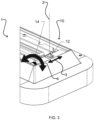
- FIGS 3 , 4 , 5A-5D to 6A and 6B show a levelling system 10 provided at each end of a body 5 of luminaire 1 according to an embodiment of the invention.
- Levelling system 10 includes a gripper 12 that securely grips cable wire 2.
- Gripper 12 may have an axial bore (not shown) through which cable wire 2 extends. Spare length of cable wire 2 may be extended through channel 13, with any excess cable wire 2 extending beyond channel 13 being clipped.
- Gripper 12 may include a mechanism that allows it to releasably grip cable wire 2 as known in the art.
- Gripper 12 may be connected to (e.g. screwed into) or integral with a shuttle 20.
- Shuttle 20 is dimensioned to slidably fit within slot 30 of housing 28.
- the length of shuttle 20 and the length of slot 30 are dimensioned so that when shuttle 20 is positioned in a leftmost position (as shown in Figure 6A ), shoulder 26 of shuttle 20 abuts edge 36 of opening 34 of housing 28, and when shuttle 20 is positioned in a rightmost position (as shown in Figure 6B ), shoulder 26' of shuttle 20 abuts edge 36' of opening 34 of housing 28.
- Thumb wheel 14 includes a head 16 and a drive shaft 18.
- Drive shaft 18 is threaded at least at its distal end. In the embodiment illustrated, drive shaft 18 is fully threaded.
- thumb wheel 14 is disposed in housing 28, with a proximal portion of drive shaft 18 within a correspondingly dimensioned bore 32 of housing 28, and a distal portion of drive shaft 18 at least partially and matingly engaged with a threaded bore 24 of shuttle 20.
- Axial displacement of thumb wheel 14 is constrained at head 16 by projection 38 and collar 40 of housing 28. Bore 32 is not threaded.
- Housing 28 has another opening 42 through which a portion of head 16 of thumb wheel 14 is exposed to allow access by a user.
- the circumferential surface of head 16 (exposed through opening 42 as it rotates) may be provided with a high friction surface (e.g. ribbing, or rubber material) for a user to more easily grip and therefore rotate head 16.
- thumb wheel 14 In operation, a user desiring to adjust the positioning of cable wire 2 rotates thumb wheel 14 at head 16 through opening 42. Thumb wheel 14 may be rotated in either of directions 4. Axial rotation of drive shaft 18 of thumb wheel 14 is translated to linear motion of shuttle 20, due to engagement of drive shaft 18 with threaded bore 24. Shuttle 20 is linearly displaced within slot 30 in directions 3 since linear displacement of thumb wheel 14 is constrained at collar 40 and projection 38 of housing 28.
- system 10 is integral with luminaire 1. In other embodiments, system 10 may be provided as a separate component from the luminaire 1, and attached to luminaire 1 before installation.
- luminaire 1 has a single point attachment with cable wires 2.
- luminaire 1 may have multi point attachments, such as a yoke-type two point attachment, with cable wires 2; in such embodiments, both attachment points for the same cable wire 2 may attach to a single shuttle 20 of a single system 10, or each attachment point of the same cable wire 2 may attach to respective shuttles 20 of respective systems 10.
- luminaire 1 may be a generally elongated rectangular shape with a cable wire 2 at each end.
- luminaire 1 may be other shapes, including but not limited to other types of polygons, circles, ovals and the like. The shapes may be symmetrical or non-symmetrical. Each shape may have two or more cable wire attachment points that are each provided with a system 10 as described herein to assist in levelling the luminaire during installation.
- a component e.g. cable wire, projection, etc.
- reference to that component should be interpreted as including as equivalents of that component any component which performs the function of the described component (i.e. that is functionally equivalent), including components which are not structurally equivalent to the disclosed structure which performs the function in the illustrated exemplary embodiments of the invention.
Landscapes
- Engineering & Computer Science (AREA)
- General Engineering & Computer Science (AREA)
- Non-Portable Lighting Devices Or Systems Thereof (AREA)
Claims (9)
- System (10) zum waagerechten Ausrichten von Hängeleuchten, wobei das System Folgendes umfasst:ein Gehäuse (28), das eine erste Öffnung (34) und eine zweite Öffnung (42) umfasst, wobei die erste Öffnung mit einer Nut (30) verbunden ist;eine Pendelvorrichtung (20), die in der Nut (30) des Gehäuses (28) angeordnet ist, wobei die Pendelvorrichtung (20) einen Greifer (12) und eine Gewindebohrung (24) umfasst;dadurch gekennzeichnet, dassein Rändelrad (14) in dem Gehäuse (28) angeordnet ist, wobei das Rändelrad (14) einen Kopf (16), der zumindest teilweise zu der zweiten Öffnung (42) freiliegt, und eine Antriebswelle (18) umfasst, die einen Gewindeabschnitt zum ineinander greifenden Eingriff mit der Gewindebohrung (24) der Pendelvorrichtung (20) umfasst;wobei eine lineare Verschiebung des Rändelrads (14) durch das Gehäuse (28) beschränkt ist; undwobei eine Drehung des Rändelrads (14) eine lineare Verschiebung der Pendelvorrichtung (20) antreibt.
- System nach Anspruch 1, wobei die erste Öffnung (34) eine erste Kante (36) und eine zweite Kante (36') umfasst, wobei die Pendelvorrichtung (20) einen ersten Ansatz (26) und einen zweiten Ansatz (26') umfasst, wobei in einer ersten Position der Pendelvorrichtung (20) der erste Ansatz (26) an der ersten Kante (36) anliegt, und wobei in einer zweiten Position der Pendelvorrichtung der zweite Ansatz (26') an der zweiten Kante (36') anliegt, wobei eine lineare Verschiebung der Pendelvorrichtung zwischen der ersten Position und der zweiten Position beschränkt ist.
- System nach Anspruch 1 oder 2, wobei das Gehäuse (28) eine gewindelose Bohrung (32) zum Halten eines proximalen Abschnitts der Antriebswelle (18) umfasst, wobei die gewindelose Bohrung mit der Nut (30) verbunden ist.
- System nach Anspruch 3, wobei das Gehäuse (28) eine Einfassung (40), die ein Ende der gewindelosen Bohrung gegenüber der Nut (30) definiert, und einen Vorsprung (38) umfasst, wobei die Einfassung und der Vorsprung zusammenwirken, um eine lineare Verschiebung des Kopfes des Rändelrads (14) zu beschränken.
- System nach einem der Ansprüche 1 bis 4, wobei der Greifer (12) eine axiale Bohrung zum Greifen eines Kabeldrahts (2) umfasst.
- System nach Anspruch 5, wobei das Gehäuse (28) einen Kanal (13) in Kommunikation mit der axialen Bohrung des Greifers (12) umfasst, wobei der Kanal (13) so dimensioniert ist, dass er eine beliebige Länge des Kabeldrahts von der axialen Bohrung des Greifers aufnimmt, wobei eine eventuelle Überlänge des Kabels, die sich über den Kanal hinaus erstreckt, durch einen Benutzer abgeschnitten werden kann.
- Leuchte (1), umfassend:einen Körper (5); undein oder mehrere Systeme nach einem der Ansprüche 1 bis 6, wobei jedes des einen oder der mehreren Systeme zumindest an einem Befestigungspunkt des Körpers mit Kabeldraht zum Aufhängen der Leuchte versehen ist.
- Verfahren zum waagerechten Ausrichten einer Hängeleuchte (1), wobei das Verfahren Folgendes umfasst:a. Bereitstellen einer Leuchte (1) nach Anspruch 7;b. Aufhängen der Leuchte an einer Decke mit Kabeldrähten;c. wenn die Hängeleuchte (1) nicht waagerecht ist, Drehen des Rändelrads mindestens eines des einen oder der mehreren Systeme, um zumindest einen der Kabeldrähte zum waagerechten Ausrichten der Hängeleuchte linear zu verschieben.
- Verfahren nach Anspruch 8, wobei Schritt c für eine Mehrzahl des einen oder der mehreren Systeme wiederholt wird.
Applications Claiming Priority (2)
| Application Number | Priority Date | Filing Date | Title |
|---|---|---|---|
| US201862634422P | 2018-02-23 | 2018-02-23 | |
| PCT/CA2019/050221 WO2019161506A1 (en) | 2018-02-23 | 2019-02-22 | Suspended luminaire levelling systems |
Publications (4)
| Publication Number | Publication Date |
|---|---|
| EP3755945A1 EP3755945A1 (de) | 2020-12-30 |
| EP3755945A4 EP3755945A4 (de) | 2021-11-24 |
| EP3755945C0 EP3755945C0 (de) | 2024-04-03 |
| EP3755945B1 true EP3755945B1 (de) | 2024-04-03 |
Family
ID=67687453
Family Applications (1)
| Application Number | Title | Priority Date | Filing Date |
|---|---|---|---|
| EP19758256.2A Active EP3755945B1 (de) | 2018-02-23 | 2019-02-22 | Nivellierungssystem für hängeleuchten |
Country Status (4)
| Country | Link |
|---|---|
| US (1) | US11365873B2 (de) |
| EP (1) | EP3755945B1 (de) |
| ES (1) | ES2985261T3 (de) |
| WO (1) | WO2019161506A1 (de) |
Families Citing this family (1)
| Publication number | Priority date | Publication date | Assignee | Title |
|---|---|---|---|---|
| WO2023131473A1 (en) * | 2022-01-04 | 2023-07-13 | Signify Holding B.V. | An adjustable suspensible device |
Citations (1)
| Publication number | Priority date | Publication date | Assignee | Title |
|---|---|---|---|---|
| US4446626A (en) * | 1982-04-12 | 1984-05-08 | Arnemann Grender | Method and apparatus for accurately setting directional headings in mining tunnels |
Family Cites Families (27)
| Publication number | Priority date | Publication date | Assignee | Title |
|---|---|---|---|---|
| US320172A (en) * | 1885-06-16 | Wrench | ||
| US626285A (en) * | 1899-06-06 | Wrench attachment for combination-tools | ||
| US3512743A (en) * | 1966-11-14 | 1970-05-19 | Willis L Lipscomb | Adjustable lighting fixture hanger with wiring protection means |
| US3919459A (en) * | 1975-02-04 | 1975-11-11 | Westinghouse Electric Corp | Luminaire ballast mounting system |
| US4044710A (en) * | 1976-04-09 | 1977-08-30 | Richard Hansen | Inventory control board |
| US6450669B2 (en) | 1999-12-16 | 2002-09-17 | America's Gardening Resource, Inc. | Light stand having a fixture height adjustment mechanism |
| JP4012365B2 (ja) * | 2000-09-29 | 2007-11-21 | 松下電工株式会社 | 昇降装置 |
| US6517222B1 (en) * | 2001-08-01 | 2003-02-11 | Linear Lighting Corp. | System and method for leveling suspended lighting fixtures and a longitudunal axis |
| US6767116B2 (en) * | 2002-09-24 | 2004-07-27 | H.E. Williams, Inc. | Lighting fixture assembly |
| US7213938B2 (en) * | 2003-04-02 | 2007-05-08 | Hubbell Incorporated | Electrical lighting fixture with suspension assembly |
| US7142358B2 (en) * | 2003-09-09 | 2006-11-28 | Gemological Institute Of America, Inc. | Gem microscope with portability kit |
| US20060196317A1 (en) * | 2005-03-03 | 2006-09-07 | Infinity Consulting Group, Llc | Adjustable ratchet wrench |
| DE202005020944U1 (de) | 2005-09-14 | 2006-12-28 | Eglo Leuchten Gmbh | Vorrichtung zum Ausrichten eines Leuchtkörpers mit exzentrischem Schwerpunkt |
| US20070246631A1 (en) * | 2006-04-14 | 2007-10-25 | Hubbell Incorporated | Automatic leveling suspension system for luminaires |
| US7284465B1 (en) * | 2006-06-08 | 2007-10-23 | Jing-Ru Chen | Locating structure of an adjustable open wrench |
| EP2118560B1 (de) | 2007-02-05 | 2013-05-01 | Louis Poulsen Lighting A/s | Anbringungseinrichtung |
| US8033519B2 (en) * | 2008-05-29 | 2011-10-11 | Mike David | Projector mount with Phillips screw driver angle adjustment |
| GB0905470D0 (en) * | 2009-03-30 | 2009-05-13 | Vitec Group Plc The | Improvement in or relating to pan and tilt heads |
| US20110024593A1 (en) * | 2009-07-29 | 2011-02-03 | Vode Lighting Llc | Fixture support system and method |
| CN102378509A (zh) * | 2010-08-09 | 2012-03-14 | 中强光电股份有限公司 | 电源装置组件 |
| US8573551B2 (en) * | 2011-08-31 | 2013-11-05 | Modernsolid Industrial Co., Ltd. | Fine-adjusting apparatus for an overhead projector |
| US8794804B2 (en) * | 2011-10-18 | 2014-08-05 | Orion Energy Systems, Inc. | System and method for supporting and leveling a light fixture |
| KR101399291B1 (ko) | 2013-01-15 | 2014-06-19 | 에스케이씨라이팅 주식회사 | 각도 조절이 가능한 조명 장치 |
| KR101429859B1 (ko) | 2013-08-14 | 2014-08-12 | 김병조 | 매달리는 부품의 균형 유지 가능한 두 줄 매다는 등기구 |
| US10041660B2 (en) * | 2015-04-06 | 2018-08-07 | Milwaukee Electric Tool Corporation | Hanging light |
| TWM517283U (zh) * | 2015-10-08 | 2016-02-11 | Unity Opto Technology Co Ltd | Led燈具 |
| US10443821B2 (en) * | 2017-06-02 | 2019-10-15 | Amax Lighting, Inc. | Modular illumination assembly |
-
2019
- 2019-02-22 EP EP19758256.2A patent/EP3755945B1/de active Active
- 2019-02-22 ES ES19758256T patent/ES2985261T3/es active Active
- 2019-02-22 US US16/971,469 patent/US11365873B2/en active Active
- 2019-02-22 WO PCT/CA2019/050221 patent/WO2019161506A1/en not_active Ceased
Patent Citations (1)
| Publication number | Priority date | Publication date | Assignee | Title |
|---|---|---|---|---|
| US4446626A (en) * | 1982-04-12 | 1984-05-08 | Arnemann Grender | Method and apparatus for accurately setting directional headings in mining tunnels |
Also Published As
| Publication number | Publication date |
|---|---|
| WO2019161506A1 (en) | 2019-08-29 |
| ES2985261T3 (es) | 2024-11-04 |
| EP3755945C0 (de) | 2024-04-03 |
| EP3755945A1 (de) | 2020-12-30 |
| US20200378587A1 (en) | 2020-12-03 |
| EP3755945A4 (de) | 2021-11-24 |
| US11365873B2 (en) | 2022-06-21 |
Similar Documents
| Publication | Publication Date | Title |
|---|---|---|
| ES2279102T3 (es) | Sistema de freno de articulacion progresivo ajustable. | |
| US10508795B2 (en) | Adjustable assembly for an adjustable downlight | |
| US10760611B2 (en) | Rotatable connection having rotational angle limitation | |
| US5317493A (en) | Apparatus for installing lighting fixture assemblies from inclined planar surfaces | |
| US9534730B2 (en) | Multi-arm gimbal system | |
| US6481871B2 (en) | Adjustable lamp support | |
| US10767807B2 (en) | Appliance stand | |
| RU2600199C2 (ru) | Устройство для управления поворотными лопатками турбомашины и турбомашина, содержащая такое устройство | |
| CN103851564A (zh) | 手动调节灯头方位的结构及灯具 | |
| US6884035B2 (en) | Fan blade attachment | |
| US9920922B2 (en) | Automatic light intensity compensating device of surgical light | |
| AU2018260846A1 (en) | A guide assembly and tool system for supporting a tool and a method for operating the same | |
| EP2118560B1 (de) | Anbringungseinrichtung | |
| US11365873B2 (en) | Suspended luminaire levelling systems | |
| CN104456464B (zh) | 照明灯具及其灯头安装支架结构 | |
| US6531683B1 (en) | Boom control system | |
| US2914661A (en) | Luminaire | |
| US10082259B1 (en) | Aperture trim assembly for recessed lighting fixture | |
| PT1425536E (pt) | Dispositivo de suspensão por cardan para um dispositivo de contrabalanço para uma câmara fotográfica | |
| CN218327025U (zh) | 一种摄像机支架 | |
| CN210687954U (zh) | 可调节照射方向的灯具 | |
| CN209511905U (zh) | 一种可调光源上下位置与光源发射角度的筒灯 | |
| US10253955B2 (en) | Lamp with rotational and linear movement | |
| EP3167838B1 (de) | Drehbare verbindung mit einem bremsungsmechanismus | |
| CN220300201U (zh) | 一种可调节吊架 |
Legal Events
| Date | Code | Title | Description |
|---|---|---|---|
| STAA | Information on the status of an ep patent application or granted ep patent |
Free format text: STATUS: THE INTERNATIONAL PUBLICATION HAS BEEN MADE |
|
| PUAI | Public reference made under article 153(3) epc to a published international application that has entered the european phase |
Free format text: ORIGINAL CODE: 0009012 |
|
| STAA | Information on the status of an ep patent application or granted ep patent |
Free format text: STATUS: REQUEST FOR EXAMINATION WAS MADE |
|
| 17P | Request for examination filed |
Effective date: 20200915 |
|
| AK | Designated contracting states |
Kind code of ref document: A1 Designated state(s): AL AT BE BG CH CY CZ DE DK EE ES FI FR GB GR HR HU IE IS IT LI LT LU LV MC MK MT NL NO PL PT RO RS SE SI SK SM TR |
|
| AX | Request for extension of the european patent |
Extension state: BA ME |
|
| DAV | Request for validation of the european patent (deleted) | ||
| DAX | Request for extension of the european patent (deleted) | ||
| RAP1 | Party data changed (applicant data changed or rights of an application transferred) |
Owner name: LMPG INC. DBA FLUXWERX ILLUMINATION |
|
| A4 | Supplementary search report drawn up and despatched |
Effective date: 20211022 |
|
| RIC1 | Information provided on ipc code assigned before grant |
Ipc: F21V 21/16 20060101ALN20211018BHEP Ipc: F21V 21/112 20060101ALI20211018BHEP Ipc: F21S 8/06 20060101AFI20211018BHEP |
|
| RAP3 | Party data changed (applicant data changed or rights of an application transferred) |
Owner name: LMPG INC. |
|
| REG | Reference to a national code |
Ref country code: DE Ref legal event code: R079 Free format text: PREVIOUS MAIN CLASS: F21V0021008000 Ipc: F21S0008060000 Ref document number: 602019049544 Country of ref document: DE |
|
| RIC1 | Information provided on ipc code assigned before grant |
Ipc: F21V 21/16 20060101ALN20230718BHEP Ipc: F21V 21/112 20060101ALI20230718BHEP Ipc: F21S 8/06 20060101AFI20230718BHEP |
|
| GRAP | Despatch of communication of intention to grant a patent |
Free format text: ORIGINAL CODE: EPIDOSNIGR1 |
|
| STAA | Information on the status of an ep patent application or granted ep patent |
Free format text: STATUS: GRANT OF PATENT IS INTENDED |
|
| RIC1 | Information provided on ipc code assigned before grant |
Ipc: F21V 21/16 20060101ALN20230825BHEP Ipc: F21V 21/112 20060101ALI20230825BHEP Ipc: F21S 8/06 20060101AFI20230825BHEP |
|
| INTG | Intention to grant announced |
Effective date: 20230927 |
|
| GRAS | Grant fee paid |
Free format text: ORIGINAL CODE: EPIDOSNIGR3 |
|
| GRAA | (expected) grant |
Free format text: ORIGINAL CODE: 0009210 |
|
| STAA | Information on the status of an ep patent application or granted ep patent |
Free format text: STATUS: THE PATENT HAS BEEN GRANTED |
|
| AK | Designated contracting states |
Kind code of ref document: B1 Designated state(s): AL AT BE BG CH CY CZ DE DK EE ES FI FR GB GR HR HU IE IS IT LI LT LU LV MC MK MT NL NO PL PT RO RS SE SI SK SM TR |
|
| REG | Reference to a national code |
Ref country code: CH Ref legal event code: EP |
|
| REG | Reference to a national code |
Ref country code: IE Ref legal event code: FG4D |
|
| REG | Reference to a national code |
Ref country code: DE Ref legal event code: R096 Ref document number: 602019049544 Country of ref document: DE |
|
| U01 | Request for unitary effect filed |
Effective date: 20240404 |
|
| U07 | Unitary effect registered |
Designated state(s): AT BE BG DE DK EE FI FR IT LT LU LV MT NL PT SE SI Effective date: 20240415 |
|
| PG25 | Lapsed in a contracting state [announced via postgrant information from national office to epo] |
Ref country code: IS Free format text: LAPSE BECAUSE OF FAILURE TO SUBMIT A TRANSLATION OF THE DESCRIPTION OR TO PAY THE FEE WITHIN THE PRESCRIBED TIME-LIMIT Effective date: 20240803 |
|
| PG25 | Lapsed in a contracting state [announced via postgrant information from national office to epo] |
Ref country code: HR Free format text: LAPSE BECAUSE OF FAILURE TO SUBMIT A TRANSLATION OF THE DESCRIPTION OR TO PAY THE FEE WITHIN THE PRESCRIBED TIME-LIMIT Effective date: 20240403 |
|
| PG25 | Lapsed in a contracting state [announced via postgrant information from national office to epo] |
Ref country code: GR Free format text: LAPSE BECAUSE OF FAILURE TO SUBMIT A TRANSLATION OF THE DESCRIPTION OR TO PAY THE FEE WITHIN THE PRESCRIBED TIME-LIMIT Effective date: 20240704 |
|
| PG25 | Lapsed in a contracting state [announced via postgrant information from national office to epo] |
Ref country code: CZ Free format text: LAPSE BECAUSE OF FAILURE TO SUBMIT A TRANSLATION OF THE DESCRIPTION OR TO PAY THE FEE WITHIN THE PRESCRIBED TIME-LIMIT Effective date: 20240403 |
|
| PG25 | Lapsed in a contracting state [announced via postgrant information from national office to epo] |
Ref country code: PL Free format text: LAPSE BECAUSE OF FAILURE TO SUBMIT A TRANSLATION OF THE DESCRIPTION OR TO PAY THE FEE WITHIN THE PRESCRIBED TIME-LIMIT Effective date: 20240403 |
|
| PG25 | Lapsed in a contracting state [announced via postgrant information from national office to epo] |
Ref country code: PL Free format text: LAPSE BECAUSE OF FAILURE TO SUBMIT A TRANSLATION OF THE DESCRIPTION OR TO PAY THE FEE WITHIN THE PRESCRIBED TIME-LIMIT Effective date: 20240403 Ref country code: NO Free format text: LAPSE BECAUSE OF FAILURE TO SUBMIT A TRANSLATION OF THE DESCRIPTION OR TO PAY THE FEE WITHIN THE PRESCRIBED TIME-LIMIT Effective date: 20240703 Ref country code: IS Free format text: LAPSE BECAUSE OF FAILURE TO SUBMIT A TRANSLATION OF THE DESCRIPTION OR TO PAY THE FEE WITHIN THE PRESCRIBED TIME-LIMIT Effective date: 20240803 Ref country code: HR Free format text: LAPSE BECAUSE OF FAILURE TO SUBMIT A TRANSLATION OF THE DESCRIPTION OR TO PAY THE FEE WITHIN THE PRESCRIBED TIME-LIMIT Effective date: 20240403 Ref country code: GR Free format text: LAPSE BECAUSE OF FAILURE TO SUBMIT A TRANSLATION OF THE DESCRIPTION OR TO PAY THE FEE WITHIN THE PRESCRIBED TIME-LIMIT Effective date: 20240704 Ref country code: CZ Free format text: LAPSE BECAUSE OF FAILURE TO SUBMIT A TRANSLATION OF THE DESCRIPTION OR TO PAY THE FEE WITHIN THE PRESCRIBED TIME-LIMIT Effective date: 20240403 Ref country code: RS Free format text: LAPSE BECAUSE OF FAILURE TO SUBMIT A TRANSLATION OF THE DESCRIPTION OR TO PAY THE FEE WITHIN THE PRESCRIBED TIME-LIMIT Effective date: 20240703 |
|
| REG | Reference to a national code |
Ref country code: ES Ref legal event code: FG2A Ref document number: 2985261 Country of ref document: ES Kind code of ref document: T3 Effective date: 20241104 |
|
| REG | Reference to a national code |
Ref country code: DE Ref legal event code: R097 Ref document number: 602019049544 Country of ref document: DE |
|
| PG25 | Lapsed in a contracting state [announced via postgrant information from national office to epo] |
Ref country code: SK Free format text: LAPSE BECAUSE OF FAILURE TO SUBMIT A TRANSLATION OF THE DESCRIPTION OR TO PAY THE FEE WITHIN THE PRESCRIBED TIME-LIMIT Effective date: 20240403 Ref country code: RO Free format text: LAPSE BECAUSE OF FAILURE TO SUBMIT A TRANSLATION OF THE DESCRIPTION OR TO PAY THE FEE WITHIN THE PRESCRIBED TIME-LIMIT Effective date: 20240403 |
|
| PG25 | Lapsed in a contracting state [announced via postgrant information from national office to epo] |
Ref country code: SM Free format text: LAPSE BECAUSE OF FAILURE TO SUBMIT A TRANSLATION OF THE DESCRIPTION OR TO PAY THE FEE WITHIN THE PRESCRIBED TIME-LIMIT Effective date: 20240403 |
|
| PG25 | Lapsed in a contracting state [announced via postgrant information from national office to epo] |
Ref country code: SM Free format text: LAPSE BECAUSE OF FAILURE TO SUBMIT A TRANSLATION OF THE DESCRIPTION OR TO PAY THE FEE WITHIN THE PRESCRIBED TIME-LIMIT Effective date: 20240403 Ref country code: SK Free format text: LAPSE BECAUSE OF FAILURE TO SUBMIT A TRANSLATION OF THE DESCRIPTION OR TO PAY THE FEE WITHIN THE PRESCRIBED TIME-LIMIT Effective date: 20240403 Ref country code: RO Free format text: LAPSE BECAUSE OF FAILURE TO SUBMIT A TRANSLATION OF THE DESCRIPTION OR TO PAY THE FEE WITHIN THE PRESCRIBED TIME-LIMIT Effective date: 20240403 |
|
| PLBE | No opposition filed within time limit |
Free format text: ORIGINAL CODE: 0009261 |
|
| STAA | Information on the status of an ep patent application or granted ep patent |
Free format text: STATUS: NO OPPOSITION FILED WITHIN TIME LIMIT |
|
| 26N | No opposition filed |
Effective date: 20250106 |
|
| U20 | Renewal fee for the european patent with unitary effect paid |
Year of fee payment: 7 Effective date: 20250227 |
|
| PG25 | Lapsed in a contracting state [announced via postgrant information from national office to epo] |
Ref country code: MC Free format text: LAPSE BECAUSE OF FAILURE TO SUBMIT A TRANSLATION OF THE DESCRIPTION OR TO PAY THE FEE WITHIN THE PRESCRIBED TIME-LIMIT Effective date: 20240403 |
|
| REG | Reference to a national code |
Ref country code: CH Ref legal event code: PL |
|
| PG25 | Lapsed in a contracting state [announced via postgrant information from national office to epo] |
Ref country code: CH Free format text: LAPSE BECAUSE OF NON-PAYMENT OF DUE FEES Effective date: 20250228 |
|
| PG25 | Lapsed in a contracting state [announced via postgrant information from national office to epo] |
Ref country code: IE Free format text: LAPSE BECAUSE OF NON-PAYMENT OF DUE FEES Effective date: 20250222 |
|
| REG | Reference to a national code |
Ref country code: ES Ref legal event code: FD2A Effective date: 20260330 |
|
| U20 | Renewal fee for the european patent with unitary effect paid |
Year of fee payment: 8 Effective date: 20260227 |
|
| PGFP | Annual fee paid to national office [announced via postgrant information from national office to epo] |
Ref country code: GB Payment date: 20260227 Year of fee payment: 8 |
|
| PG25 | Lapsed in a contracting state [announced via postgrant information from national office to epo] |
Ref country code: ES Free format text: LAPSE BECAUSE OF NON-PAYMENT OF DUE FEES Effective date: 20250223 |