EP3755940B1 - Kopf für einen aufbewahrungsbehälter für flüssigkeiten - Google Patents
Kopf für einen aufbewahrungsbehälter für flüssigkeiten Download PDFInfo
- Publication number
- EP3755940B1 EP3755940B1 EP19741483.2A EP19741483A EP3755940B1 EP 3755940 B1 EP3755940 B1 EP 3755940B1 EP 19741483 A EP19741483 A EP 19741483A EP 3755940 B1 EP3755940 B1 EP 3755940B1
- Authority
- EP
- European Patent Office
- Prior art keywords
- container
- head
- tube
- nitrogen
- core
- Prior art date
- Legal status (The legal status is an assumption and is not a legal conclusion. Google has not performed a legal analysis and makes no representation as to the accuracy of the status listed.)
- Active
Links
Images


Classifications
-
- F—MECHANICAL ENGINEERING; LIGHTING; HEATING; WEAPONS; BLASTING
- F17—STORING OR DISTRIBUTING GASES OR LIQUIDS
- F17C—VESSELS FOR CONTAINING OR STORING COMPRESSED, LIQUEFIED OR SOLIDIFIED GASES; FIXED-CAPACITY GAS-HOLDERS; FILLING VESSELS WITH, OR DISCHARGING FROM VESSELS, COMPRESSED, LIQUEFIED, OR SOLIDIFIED GASES
- F17C13/00—Details of vessels or of the filling or discharging of vessels
- F17C13/02—Special adaptations of indicating, measuring, or monitoring equipment
- F17C13/021—Special adaptations of indicating, measuring, or monitoring equipment having the height as the parameter
-
- B—PERFORMING OPERATIONS; TRANSPORTING
- B65—CONVEYING; PACKING; STORING; HANDLING THIN OR FILAMENTARY MATERIAL
- B65D—CONTAINERS FOR STORAGE OR TRANSPORT OF ARTICLES OR MATERIALS, e.g. BAGS, BARRELS, BOTTLES, BOXES, CANS, CARTONS, CRATES, DRUMS, JARS, TANKS, HOPPERS, FORWARDING CONTAINERS; ACCESSORIES, CLOSURES, OR FITTINGS THEREFOR; PACKAGING ELEMENTS; PACKAGES
- B65D51/00—Closures not otherwise provided for
- B65D51/24—Closures not otherwise provided for combined or co-operating with auxiliary devices for non-closing purposes
-
- G—PHYSICS
- G01—MEASURING; TESTING
- G01F—MEASURING VOLUME, VOLUME FLOW, MASS FLOW OR LIQUID LEVEL; METERING BY VOLUME
- G01F23/00—Indicating or measuring liquid level or level of fluent solid material, e.g. indicating in terms of volume or indicating by means of an alarm
- G01F23/22—Indicating or measuring liquid level or level of fluent solid material, e.g. indicating in terms of volume or indicating by means of an alarm by measuring physical variables, other than linear dimensions, pressure or weight, dependent on the level to be measured, e.g. by difference of heat transfer of steam or water
- G01F23/26—Indicating or measuring liquid level or level of fluent solid material, e.g. indicating in terms of volume or indicating by means of an alarm by measuring physical variables, other than linear dimensions, pressure or weight, dependent on the level to be measured, e.g. by difference of heat transfer of steam or water by measuring variations of capacity or inductance of capacitors or inductors arising from the presence of liquid or fluent solid material in the electric or electromagnetic fields
- G01F23/263—Indicating or measuring liquid level or level of fluent solid material, e.g. indicating in terms of volume or indicating by means of an alarm by measuring physical variables, other than linear dimensions, pressure or weight, dependent on the level to be measured, e.g. by difference of heat transfer of steam or water by measuring variations of capacity or inductance of capacitors or inductors arising from the presence of liquid or fluent solid material in the electric or electromagnetic fields by measuring variations in capacitance of capacitors
-
- F—MECHANICAL ENGINEERING; LIGHTING; HEATING; WEAPONS; BLASTING
- F17—STORING OR DISTRIBUTING GASES OR LIQUIDS
- F17C—VESSELS FOR CONTAINING OR STORING COMPRESSED, LIQUEFIED OR SOLIDIFIED GASES; FIXED-CAPACITY GAS-HOLDERS; FILLING VESSELS WITH, OR DISCHARGING FROM VESSELS, COMPRESSED, LIQUEFIED, OR SOLIDIFIED GASES
- F17C2201/00—Vessel construction, in particular geometry, arrangement or size
- F17C2201/01—Shape
- F17C2201/0104—Shape cylindrical
-
- F—MECHANICAL ENGINEERING; LIGHTING; HEATING; WEAPONS; BLASTING
- F17—STORING OR DISTRIBUTING GASES OR LIQUIDS
- F17C—VESSELS FOR CONTAINING OR STORING COMPRESSED, LIQUEFIED OR SOLIDIFIED GASES; FIXED-CAPACITY GAS-HOLDERS; FILLING VESSELS WITH, OR DISCHARGING FROM VESSELS, COMPRESSED, LIQUEFIED, OR SOLIDIFIED GASES
- F17C2201/00—Vessel construction, in particular geometry, arrangement or size
- F17C2201/03—Orientation
- F17C2201/032—Orientation with substantially vertical main axis
-
- F—MECHANICAL ENGINEERING; LIGHTING; HEATING; WEAPONS; BLASTING
- F17—STORING OR DISTRIBUTING GASES OR LIQUIDS
- F17C—VESSELS FOR CONTAINING OR STORING COMPRESSED, LIQUEFIED OR SOLIDIFIED GASES; FIXED-CAPACITY GAS-HOLDERS; FILLING VESSELS WITH, OR DISCHARGING FROM VESSELS, COMPRESSED, LIQUEFIED, OR SOLIDIFIED GASES
- F17C2201/00—Vessel construction, in particular geometry, arrangement or size
- F17C2201/05—Size
- F17C2201/056—Small (<1 m3)
-
- F—MECHANICAL ENGINEERING; LIGHTING; HEATING; WEAPONS; BLASTING
- F17—STORING OR DISTRIBUTING GASES OR LIQUIDS
- F17C—VESSELS FOR CONTAINING OR STORING COMPRESSED, LIQUEFIED OR SOLIDIFIED GASES; FIXED-CAPACITY GAS-HOLDERS; FILLING VESSELS WITH, OR DISCHARGING FROM VESSELS, COMPRESSED, LIQUEFIED, OR SOLIDIFIED GASES
- F17C2201/00—Vessel construction, in particular geometry, arrangement or size
- F17C2201/05—Size
- F17C2201/058—Size portable (<30 l)
-
- F—MECHANICAL ENGINEERING; LIGHTING; HEATING; WEAPONS; BLASTING
- F17—STORING OR DISTRIBUTING GASES OR LIQUIDS
- F17C—VESSELS FOR CONTAINING OR STORING COMPRESSED, LIQUEFIED OR SOLIDIFIED GASES; FIXED-CAPACITY GAS-HOLDERS; FILLING VESSELS WITH, OR DISCHARGING FROM VESSELS, COMPRESSED, LIQUEFIED, OR SOLIDIFIED GASES
- F17C2203/00—Vessel construction, in particular walls or details thereof
- F17C2203/03—Thermal insulations
- F17C2203/0391—Thermal insulations by vacuum
-
- F—MECHANICAL ENGINEERING; LIGHTING; HEATING; WEAPONS; BLASTING
- F17—STORING OR DISTRIBUTING GASES OR LIQUIDS
- F17C—VESSELS FOR CONTAINING OR STORING COMPRESSED, LIQUEFIED OR SOLIDIFIED GASES; FIXED-CAPACITY GAS-HOLDERS; FILLING VESSELS WITH, OR DISCHARGING FROM VESSELS, COMPRESSED, LIQUEFIED, OR SOLIDIFIED GASES
- F17C2203/00—Vessel construction, in particular walls or details thereof
- F17C2203/06—Materials for walls or layers thereof; Properties or structures of walls or their materials
- F17C2203/0602—Wall structures; Special features thereof
- F17C2203/0612—Wall structures
- F17C2203/0626—Multiple walls
- F17C2203/0629—Two walls
-
- F—MECHANICAL ENGINEERING; LIGHTING; HEATING; WEAPONS; BLASTING
- F17—STORING OR DISTRIBUTING GASES OR LIQUIDS
- F17C—VESSELS FOR CONTAINING OR STORING COMPRESSED, LIQUEFIED OR SOLIDIFIED GASES; FIXED-CAPACITY GAS-HOLDERS; FILLING VESSELS WITH, OR DISCHARGING FROM VESSELS, COMPRESSED, LIQUEFIED, OR SOLIDIFIED GASES
- F17C2205/00—Vessel construction, in particular mounting arrangements, attachments or identifications means
- F17C2205/01—Mounting arrangements
- F17C2205/0153—Details of mounting arrangements
- F17C2205/0157—Details of mounting arrangements for transport
- F17C2205/0161—Details of mounting arrangements for transport with wheels
-
- F—MECHANICAL ENGINEERING; LIGHTING; HEATING; WEAPONS; BLASTING
- F17—STORING OR DISTRIBUTING GASES OR LIQUIDS
- F17C—VESSELS FOR CONTAINING OR STORING COMPRESSED, LIQUEFIED OR SOLIDIFIED GASES; FIXED-CAPACITY GAS-HOLDERS; FILLING VESSELS WITH, OR DISCHARGING FROM VESSELS, COMPRESSED, LIQUEFIED, OR SOLIDIFIED GASES
- F17C2205/00—Vessel construction, in particular mounting arrangements, attachments or identifications means
- F17C2205/03—Fluid connections, filters, valves, closure means or other attachments
- F17C2205/0302—Fittings, valves, filters, or components in connection with the gas storage device
- F17C2205/0311—Closure means
-
- F—MECHANICAL ENGINEERING; LIGHTING; HEATING; WEAPONS; BLASTING
- F17—STORING OR DISTRIBUTING GASES OR LIQUIDS
- F17C—VESSELS FOR CONTAINING OR STORING COMPRESSED, LIQUEFIED OR SOLIDIFIED GASES; FIXED-CAPACITY GAS-HOLDERS; FILLING VESSELS WITH, OR DISCHARGING FROM VESSELS, COMPRESSED, LIQUEFIED, OR SOLIDIFIED GASES
- F17C2205/00—Vessel construction, in particular mounting arrangements, attachments or identifications means
- F17C2205/03—Fluid connections, filters, valves, closure means or other attachments
- F17C2205/0302—Fittings, valves, filters, or components in connection with the gas storage device
- F17C2205/0323—Valves
-
- F—MECHANICAL ENGINEERING; LIGHTING; HEATING; WEAPONS; BLASTING
- F17—STORING OR DISTRIBUTING GASES OR LIQUIDS
- F17C—VESSELS FOR CONTAINING OR STORING COMPRESSED, LIQUEFIED OR SOLIDIFIED GASES; FIXED-CAPACITY GAS-HOLDERS; FILLING VESSELS WITH, OR DISCHARGING FROM VESSELS, COMPRESSED, LIQUEFIED, OR SOLIDIFIED GASES
- F17C2205/00—Vessel construction, in particular mounting arrangements, attachments or identifications means
- F17C2205/03—Fluid connections, filters, valves, closure means or other attachments
- F17C2205/0302—Fittings, valves, filters, or components in connection with the gas storage device
- F17C2205/0382—Constructional details of valves, regulators
- F17C2205/0385—Constructional details of valves, regulators in blocks or units
-
- F—MECHANICAL ENGINEERING; LIGHTING; HEATING; WEAPONS; BLASTING
- F17—STORING OR DISTRIBUTING GASES OR LIQUIDS
- F17C—VESSELS FOR CONTAINING OR STORING COMPRESSED, LIQUEFIED OR SOLIDIFIED GASES; FIXED-CAPACITY GAS-HOLDERS; FILLING VESSELS WITH, OR DISCHARGING FROM VESSELS, COMPRESSED, LIQUEFIED, OR SOLIDIFIED GASES
- F17C2221/00—Handled fluid, in particular type of fluid
- F17C2221/01—Pure fluids
- F17C2221/014—Nitrogen
-
- F—MECHANICAL ENGINEERING; LIGHTING; HEATING; WEAPONS; BLASTING
- F17—STORING OR DISTRIBUTING GASES OR LIQUIDS
- F17C—VESSELS FOR CONTAINING OR STORING COMPRESSED, LIQUEFIED OR SOLIDIFIED GASES; FIXED-CAPACITY GAS-HOLDERS; FILLING VESSELS WITH, OR DISCHARGING FROM VESSELS, COMPRESSED, LIQUEFIED, OR SOLIDIFIED GASES
- F17C2221/00—Handled fluid, in particular type of fluid
- F17C2221/01—Pure fluids
- F17C2221/016—Noble gases (Ar, Kr, Xe)
- F17C2221/017—Helium
-
- F—MECHANICAL ENGINEERING; LIGHTING; HEATING; WEAPONS; BLASTING
- F17—STORING OR DISTRIBUTING GASES OR LIQUIDS
- F17C—VESSELS FOR CONTAINING OR STORING COMPRESSED, LIQUEFIED OR SOLIDIFIED GASES; FIXED-CAPACITY GAS-HOLDERS; FILLING VESSELS WITH, OR DISCHARGING FROM VESSELS, COMPRESSED, LIQUEFIED, OR SOLIDIFIED GASES
- F17C2221/00—Handled fluid, in particular type of fluid
- F17C2221/03—Mixtures
- F17C2221/032—Hydrocarbons
- F17C2221/035—Propane butane, e.g. LPG, GPL
-
- F—MECHANICAL ENGINEERING; LIGHTING; HEATING; WEAPONS; BLASTING
- F17—STORING OR DISTRIBUTING GASES OR LIQUIDS
- F17C—VESSELS FOR CONTAINING OR STORING COMPRESSED, LIQUEFIED OR SOLIDIFIED GASES; FIXED-CAPACITY GAS-HOLDERS; FILLING VESSELS WITH, OR DISCHARGING FROM VESSELS, COMPRESSED, LIQUEFIED, OR SOLIDIFIED GASES
- F17C2223/00—Handled fluid before transfer, i.e. state of fluid when stored in the vessel or before transfer from the vessel
- F17C2223/01—Handled fluid before transfer, i.e. state of fluid when stored in the vessel or before transfer from the vessel characterised by the phase
- F17C2223/0146—Two-phase
- F17C2223/0153—Liquefied gas, e.g. LPG, GPL
- F17C2223/0161—Liquefied gas, e.g. LPG, GPL cryogenic, e.g. LNG, GNL, PLNG
-
- F—MECHANICAL ENGINEERING; LIGHTING; HEATING; WEAPONS; BLASTING
- F17—STORING OR DISTRIBUTING GASES OR LIQUIDS
- F17C—VESSELS FOR CONTAINING OR STORING COMPRESSED, LIQUEFIED OR SOLIDIFIED GASES; FIXED-CAPACITY GAS-HOLDERS; FILLING VESSELS WITH, OR DISCHARGING FROM VESSELS, COMPRESSED, LIQUEFIED, OR SOLIDIFIED GASES
- F17C2223/00—Handled fluid before transfer, i.e. state of fluid when stored in the vessel or before transfer from the vessel
- F17C2223/03—Handled fluid before transfer, i.e. state of fluid when stored in the vessel or before transfer from the vessel characterised by the pressure level
- F17C2223/033—Small pressure, e.g. for liquefied gas
-
- F—MECHANICAL ENGINEERING; LIGHTING; HEATING; WEAPONS; BLASTING
- F17—STORING OR DISTRIBUTING GASES OR LIQUIDS
- F17C—VESSELS FOR CONTAINING OR STORING COMPRESSED, LIQUEFIED OR SOLIDIFIED GASES; FIXED-CAPACITY GAS-HOLDERS; FILLING VESSELS WITH, OR DISCHARGING FROM VESSELS, COMPRESSED, LIQUEFIED, OR SOLIDIFIED GASES
- F17C2250/00—Accessories; Control means; Indicating, measuring or monitoring of parameters
- F17C2250/04—Indicating or measuring of parameters as input values
- F17C2250/0404—Parameters indicated or measured
- F17C2250/0408—Level of content in the vessel
- F17C2250/0417—Level of content in the vessel with electrical means
-
- F—MECHANICAL ENGINEERING; LIGHTING; HEATING; WEAPONS; BLASTING
- F17—STORING OR DISTRIBUTING GASES OR LIQUIDS
- F17C—VESSELS FOR CONTAINING OR STORING COMPRESSED, LIQUEFIED OR SOLIDIFIED GASES; FIXED-CAPACITY GAS-HOLDERS; FILLING VESSELS WITH, OR DISCHARGING FROM VESSELS, COMPRESSED, LIQUEFIED, OR SOLIDIFIED GASES
- F17C2250/00—Accessories; Control means; Indicating, measuring or monitoring of parameters
- F17C2250/04—Indicating or measuring of parameters as input values
- F17C2250/0486—Indicating or measuring characterised by the location
- F17C2250/0491—Parameters measured at or inside the vessel
-
- F—MECHANICAL ENGINEERING; LIGHTING; HEATING; WEAPONS; BLASTING
- F17—STORING OR DISTRIBUTING GASES OR LIQUIDS
- F17C—VESSELS FOR CONTAINING OR STORING COMPRESSED, LIQUEFIED OR SOLIDIFIED GASES; FIXED-CAPACITY GAS-HOLDERS; FILLING VESSELS WITH, OR DISCHARGING FROM VESSELS, COMPRESSED, LIQUEFIED, OR SOLIDIFIED GASES
- F17C2250/00—Accessories; Control means; Indicating, measuring or monitoring of parameters
- F17C2250/06—Controlling or regulating of parameters as output values
- F17C2250/0605—Parameters
- F17C2250/061—Level of content in the vessel
-
- F—MECHANICAL ENGINEERING; LIGHTING; HEATING; WEAPONS; BLASTING
- F17—STORING OR DISTRIBUTING GASES OR LIQUIDS
- F17C—VESSELS FOR CONTAINING OR STORING COMPRESSED, LIQUEFIED OR SOLIDIFIED GASES; FIXED-CAPACITY GAS-HOLDERS; FILLING VESSELS WITH, OR DISCHARGING FROM VESSELS, COMPRESSED, LIQUEFIED, OR SOLIDIFIED GASES
- F17C2250/00—Accessories; Control means; Indicating, measuring or monitoring of parameters
- F17C2250/06—Controlling or regulating of parameters as output values
- F17C2250/0605—Parameters
- F17C2250/0631—Temperature
-
- F—MECHANICAL ENGINEERING; LIGHTING; HEATING; WEAPONS; BLASTING
- F17—STORING OR DISTRIBUTING GASES OR LIQUIDS
- F17C—VESSELS FOR CONTAINING OR STORING COMPRESSED, LIQUEFIED OR SOLIDIFIED GASES; FIXED-CAPACITY GAS-HOLDERS; FILLING VESSELS WITH, OR DISCHARGING FROM VESSELS, COMPRESSED, LIQUEFIED, OR SOLIDIFIED GASES
- F17C2260/00—Purposes of gas storage and gas handling
- F17C2260/02—Improving properties related to fluid or fluid transfer
- F17C2260/024—Improving metering
-
- F—MECHANICAL ENGINEERING; LIGHTING; HEATING; WEAPONS; BLASTING
- F17—STORING OR DISTRIBUTING GASES OR LIQUIDS
- F17C—VESSELS FOR CONTAINING OR STORING COMPRESSED, LIQUEFIED OR SOLIDIFIED GASES; FIXED-CAPACITY GAS-HOLDERS; FILLING VESSELS WITH, OR DISCHARGING FROM VESSELS, COMPRESSED, LIQUEFIED, OR SOLIDIFIED GASES
- F17C2265/00—Effects achieved by gas storage or gas handling
- F17C2265/04—Effects achieved by gas storage or gas handling using an independent energy source, e.g. battery
-
- F—MECHANICAL ENGINEERING; LIGHTING; HEATING; WEAPONS; BLASTING
- F17—STORING OR DISTRIBUTING GASES OR LIQUIDS
- F17C—VESSELS FOR CONTAINING OR STORING COMPRESSED, LIQUEFIED OR SOLIDIFIED GASES; FIXED-CAPACITY GAS-HOLDERS; FILLING VESSELS WITH, OR DISCHARGING FROM VESSELS, COMPRESSED, LIQUEFIED, OR SOLIDIFIED GASES
- F17C2270/00—Applications
- F17C2270/02—Applications for medical applications
-
- F—MECHANICAL ENGINEERING; LIGHTING; HEATING; WEAPONS; BLASTING
- F17—STORING OR DISTRIBUTING GASES OR LIQUIDS
- F17C—VESSELS FOR CONTAINING OR STORING COMPRESSED, LIQUEFIED OR SOLIDIFIED GASES; FIXED-CAPACITY GAS-HOLDERS; FILLING VESSELS WITH, OR DISCHARGING FROM VESSELS, COMPRESSED, LIQUEFIED, OR SOLIDIFIED GASES
- F17C2270/00—Applications
- F17C2270/05—Applications for industrial use
- F17C2270/0509—"Dewar" vessels
-
- G—PHYSICS
- G01—MEASURING; TESTING
- G01F—MEASURING VOLUME, VOLUME FLOW, MASS FLOW OR LIQUID LEVEL; METERING BY VOLUME
- G01F25/00—Testing or calibration of apparatus for measuring volume, volume flow or liquid level or for metering by volume
- G01F25/20—Testing or calibration of apparatus for measuring volume, volume flow or liquid level or for metering by volume of apparatus for measuring liquid level
Definitions
- the invention relates to a functional closure head for a non-pressurised liquid container.
- the invention can be applied in containers for transport and storage of liquids, particularly cryogenic liquids, under non-pressurised conditions.
- liquids constitutes one of fundamental types of storage. Edible, technical, industrial types of liquids are stored. They are stored in conditions, in which obtaining pressure inside the container is required to maintain the liquid phase, and under atmospheric pressure conditions. Each of these cases requires a container that is closed by a functional cover. Its design complexity level and functions depend on the liquid being stored. Liquefied gases, such as helium, nitrogen, or technical gas mixtures like propane/butane, can be classified as liquids. They require specialised storage conditions, especially those having a low boiling point (helium, propane/butane), as well as dedicated solutions related to the container closures. One distinct example of such a gas is nitrogen.
- Nitrogen can be stored in pressurised containers, which facilitates its evacuation from the container, as well as in non-pressurised containers.
- pressurised containers closures requiring special training or qualified personnel are applied. Operating a non-pressurised container is definitely easier.
- the structure of closures for pressurised containers is simpler.
- the change of design enables filling and storing the liquid, as well as using it by unqualified personnel. Nonetheless, present solutions for measuring the nitrogen inside the container require constant connection to the main power supply, which is not possible for mobile devices or can limit their functionality.
- US5488831 discloses a closure structure comprising a plug with a through-opening, a second opening closed with a bottom, in which a handle for lifting the plug is located.
- the first opening comprises a profiled tube with a crimp on one end (the one located inside the container), and a bronze filter on the other end.
- the closure according to the cited document allows only for pumping out the contents of the container, with no possibility of controlling the level of fluid after closing the container. In order to fill the container, it is necessary to open it and supply the fluid directly through the neck of the container.
- the device consists of two elements: the interior and the exterior one.
- the interior element is constituted by a heater placed on the wall and on the bottom of the container.
- the exterior element is shaped as a ring, which is mounted on the neck of the nitrogen container. Inside the ring, the heater switch, fuses and the time controller are placed.
- the container neck is closed by a cover with a profiled tube outlet.
- the solution according to the cited document requires direct connection to the main power supply. It is also impossible to control the amount of fluid inside the container after turning the heater on. In order to refill the container, the cover with the profiled tube needs to be removed.
- Document CN2058476U discloses a utility model for an automatic injector for a liquid nitrogen container comprising a nozzle, a cover, a conduit, a partition board plug, a resistance wire, a decompressing nozzle, a voltage regulator, a decompressing valve.
- the nozzle has a supporting and inserting connection to a liquid nitrogen Dewar bottle.
- the resistance wire is switched on to heating, which can cause evaporation of liquid nitrogen and an increase in pressure in the dew bottle, then the liquid nitrogen is ejected out automatically from the nozzle.
- the disclosed device operates only under conditions of constant power supply from an outside network. Operation takes place only in one direction, i.e. there is no possibility to apply it to fill the container.
- Document JP2000018494A discloses a device for supplying liquid nitrogen to analytical and research apparatuses.
- the main body is placed in the neck of the liquid nitrogen container.
- through-holes are located, in which the liquid nitrogen outlet pipe and the liquid nitrogen heater shaft are placed.
- nitrogen level point sensors are located, distributed thereon in three places spaced from each other.
- a safety valve is also located.
- the liquid nitrogen outlet pipe ends with a flange and a screw connection enabling connecting to an external apparatus.
- a controller with a display and connection to the main power supply are located.
- Discharging the nitrogen takes place by obtaining a nitrogen vapour pressure in the container, which consequently pushes out the liquid through the outlet pipe.
- This solution does not allow filling and discharging the liquid nitrogen container without disassembling it. Moreover, it also requires an outside power supply.
- the nitrogen level inside the container is monitored in three points, which prevents accurate measuring of it.
- the invention relates to a head for a container for storage of fluids, comprising a head body, characterised in that a through sleeve is located inside the head body, wherein a protection tube is coupled to the through sleeve in the lower part of the head body, and a liquid level capacitive sensor is mounted in the lower part of the body, a gland coupled with a flange to an electronic junction box powered by a battery or an accumulator is located in the upper part of the body, comprising a circuit board equipped with a microcontroller and a diode gauge, and conduits terminated with a plug extend from the box.
- Microcontroller receives a signal from the capacitive sensor related to the present nitrogen level, the signal is processed and the level value is presented on a bargraph in a 10-step scale, additionally, during refilling of the container, the increase of nitrogen level is signalled by an intermittent sound in range of 95% to 99%, and a constant sound signal at 100% fill, after connecting the head to the device, the sensor switches its power supply to the power supply from the device, after disconnecting the sensor again, it is only necessary to prompt the sensor using a push-button, mounted on the electronic junction box (4), in order to switch the power supply to the battery or accumulators, moreover, the sensor has a programmed function of temporary shutting down the power supply if the device is disconnected from the power supply, in order to prevent battery/accumulator discharge, the electrical junction box is connected to the device with conduits terminated with a plug, one of these conduits relays information about the present nitrogen level, which can be displayed on the device screen.
- the connection is used also for calibrating the sensor, determining the extreme capacities of the capacitor (0% and 100% nitrogen level).
- the protection tube is perforated.
- the capacitive sensor comprises a cylindrical capacitor with varying electric permittivity, comprising a tube with a core of length equal to the length of the tube placed inside it, and spacers made of non-conductive material are placed on the core, wherein electrical conduits are connected to the upper endings of the tube and the core.
- a heater ending with a heating spiral is mounted in the lower part of the body. The liquid nitrogen, flowing from the bottom to the vertically mounted sensor sets on the same level as the nitrogen in the entire container. Thus, the content of the capacitor changes, which allows computing the current nitrogen level.
- a suitable structure of the head provides secure operation of the device. During proper use, the head is not removed from the container (the fastening is sealed). This prevents the operator, or a person performing the filling, from contacting the liquid (e.g. liquid nitrogen) and the heating element. Additionally, the head is equipped with a perforated tube, enabling placing the rod / filling hose inside the container. It lowers the probability of burning with the fluid during filling and simultaneously protects from damaging the liquid level sensor/meter.
- the liquid nitrogen level meter functions based on the operation of the capacitive sensor, i.e. the cylindrical capacitor with varying electric permittivity between the plates (along with the change of liquid nitrogen level).
- the complex of sensor core, outside tube, spacers, and mounting elements is coupled to the head.
- the electronic junction box mounted on the outside of the non-pressurised container is an integral part of the sensor.
- the electrical junction box is equipped with battery power supply and a diode gauge. This way, when the container is disconnected from the rest of the device, it is possible to observe the nitrogen level inside the container on a 10-step scale in real time. Additionally, during filling, if the maximum nitrogen level is reached inside the container, an acoustic signaller (a buzzer) is activated inside the box, warning about overflow.
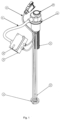
- fig. 1 illustrates the head assembly for a storage container for fluids
- fig. 2 illustrates a cross-section of the head placed in the container
- fig. 3 illustrates an elevation view of the outside surface of the container with a mounted head and visible electronic junction box
- fig. 4 illustrates an elevation view of the container presenting the placement of the head on the outside surface of the container relative to the placement of the head elements inside the container
- fig. 5 illustrates the fluid level sensor and its cross-section.
- the head of a storage container 5 for fluids comprises a head body, comprising a through sleeve 10, wherein a perforated protection tube 2 is coupled to the through sleeve 10 in the lower part of the head body.
- a capacitive liquid level sensor 3 is mounted in the lower part of the body, and a gland coupled with a flange to an electronic junction box 4 powered by a battery or an accumulator is located in the upper part of the body, comprising a circuit board equipped with a microcontroller and a diode gauge 6.
- Conduits terminated with a plug extend from the electronic junction box 4.
- a heater 1 ending with a heating spiral is mounted in the lower part of the body.
- the capacitive sensor 3 comprises a cylindrical capacitor with varying electric permittivity, comprising a tube 7 with a core 8 of length equal to the length of the tube placed inside it, and spacers 9 made of non-conductive material are placed on the core, wherein electrical conduits are connected to the upper endings of the tube and the core.
- the invention is applied in a device used for local cryotherapy. A hose is connected to the outside outlet of the head. After turning on the heater, the temperature inside the container rises, as a consequence of that, the nitrogen starts to evaporate more intensely through the coupled hose. The operator observes the nitrogen level decrease in real time. When the level reaches minimum, it is safe to fill the container.
- the sensor In order to prepare the container for secure filling, the sensor is prompted with a push-button. The power supply is then connected to the batteries/accumulators. The filling is commenced, which, due to the perforated tube installed, limits the risk of the liquid fraction of the fluid leaving the container. During refilling of the container, the nitrogen level is observed on a specialised bargraph. This enables controlling the filling level of the container.
- a box with battery power supply is present, which allows measuring the liquid level inside the container without the external power supply.
Landscapes
- Engineering & Computer Science (AREA)
- Mechanical Engineering (AREA)
- Physics & Mathematics (AREA)
- General Engineering & Computer Science (AREA)
- Power Engineering (AREA)
- Electromagnetism (AREA)
- Thermal Sciences (AREA)
- Fluid Mechanics (AREA)
- General Physics & Mathematics (AREA)
- Measurement Of Levels Of Liquids Or Fluent Solid Materials (AREA)
- Basic Packing Technique (AREA)
Claims (4)
- Aufsatz für einen Vorratsbehälter (5) für Flüssigkeiten, umfassend einen Aufsatzkorpus, dadurch gekennzeichnet, dass sich eine Durchsteckhülse (10) innerhalb des Aufsatzkorpus befindet, wobei im unteren Teil des Aufsatzkorpus ein Schutzrohr (2) an die Durchsteckhülse (10) gekoppelt ist und im unteren Teil des Korpus ein Flüssigkeitspegelsensor (3) montiert ist, sich eine Stopfbüchse (14), die mit einem Flansch (11) an einen elektronischen Kabelkasten (4), der durch eine Batterie oder einen Akkumulator mit Strom versorgt wird, gekoppelt ist, im oberen Teil des Korpus befindet und eine Leiterplatte, die mit einem Mikrocontroller (13) und einer Diodenlehre (6) ausgestattet ist, umfasst und sich Leitungen, die mit einem Stecker (12) abschließen, von dem elektronischen Kabelkasten (4) weg erstrecken und der Aufsatzkorpus an seinem unteren Teil einen flachen Kopplungsflansch (15) umfasst, wobei das Schutzrohr (2) perforiert ist.
- Behälteraufsatz gemäß Anspruch 1, dadurch gekennzeichnet, dass ein Heizgerät (1), das mit einer Heizspirale endet, im unteren Teil des Korpus montiert ist.
- Behälteraufsatz gemäß Anspruch 1, dadurch gekennzeichnet, dass der Flüssigkeitspegelsensor (3) ein kapazitiver Sensor ist.
- Behälteraufsatz gemäß Anspruch 3, dadurch gekennzeichnet, dass der Flüssigkeitspegelsensor (3) einen zylindrischen Kondensator mit variabler Dielektrizitätskonstante umfasst, ein Rohr (7) mit einem in seinem Innern platzierten Kern (8) gleicher Länge wie das Rohr (7) umfasst; und sich Abstandshalter (9) aus nichtleitendem Material auf dem Kern (8) befinden, wobei elektrische Leitungen mit den oberen Enden des Rohrs (7) und dem Kern (8) verbunden sind.
Applications Claiming Priority (2)
| Application Number | Priority Date | Filing Date | Title |
|---|---|---|---|
| PL424316A PL424316A1 (pl) | 2018-01-19 | 2018-01-19 | Głowica zbiornika do przechowywania cieczy |
| PCT/PL2019/050003 WO2019143260A1 (en) | 2018-01-19 | 2019-01-18 | Head for a storage container for liquids |
Publications (4)
| Publication Number | Publication Date |
|---|---|
| EP3755940A1 EP3755940A1 (de) | 2020-12-30 |
| EP3755940A4 EP3755940A4 (de) | 2021-12-22 |
| EP3755940C0 EP3755940C0 (de) | 2024-03-13 |
| EP3755940B1 true EP3755940B1 (de) | 2024-03-13 |
Family
ID=67301556
Family Applications (1)
| Application Number | Title | Priority Date | Filing Date |
|---|---|---|---|
| EP19741483.2A Active EP3755940B1 (de) | 2018-01-19 | 2019-01-18 | Kopf für einen aufbewahrungsbehälter für flüssigkeiten |
Country Status (5)
| Country | Link |
|---|---|
| US (1) | US20200339324A1 (de) |
| EP (1) | EP3755940B1 (de) |
| CN (1) | CN111727344A (de) |
| PL (1) | PL424316A1 (de) |
| WO (1) | WO2019143260A1 (de) |
Families Citing this family (2)
| Publication number | Priority date | Publication date | Assignee | Title |
|---|---|---|---|---|
| US12170012B2 (en) * | 2019-08-19 | 2024-12-17 | Detech, Llc | Container content monitoring device and system |
| KR102228698B1 (ko) * | 2020-05-26 | 2021-03-18 | 주식회사 케이씨 | 가스 공급 장치 |
Family Cites Families (22)
| Publication number | Priority date | Publication date | Assignee | Title |
|---|---|---|---|---|
| US2963908A (en) * | 1955-04-19 | 1960-12-13 | Sun Oil Co | Apparatus for impedance measurements |
| US3279252A (en) * | 1963-09-18 | 1966-10-18 | Monsanto Co | Level sensing apparatus |
| FR2394040A1 (fr) * | 1977-06-09 | 1979-01-05 | Automatis Regul Appar Mes Et | Dispositif d'alimentation pour cryostat |
| GB2070434B (en) * | 1980-03-04 | 1984-02-29 | Vyzk Ustav Silnoproude Elekt | Cryogenic apparatus for surgery |
| GB8306228D0 (en) * | 1983-03-07 | 1983-04-13 | Braude E Ltd | Conductive sensor elements |
| EP0175047A3 (de) * | 1984-09-18 | 1987-04-29 | CRIO GmbH Medizintechnik Kirschenmann + Schweizer | Gerät zur Tieftemperatur-Behandlung rheumatischer Erkrankungen |
| WO1990008304A1 (en) * | 1989-01-19 | 1990-07-26 | Europa International Manufacturing Pty Ltd. | Level sensor |
| DE3904824A1 (de) * | 1989-02-17 | 1990-08-23 | Gok Gmbh & Co Kg | Inhaltsanzeiger fuer fluessiggasbehaelter |
| US5103368A (en) * | 1990-05-07 | 1992-04-07 | Therm-O-Disc, Incorporated | Capacitive fluid level sensor |
| WO1992009867A1 (en) * | 1990-11-22 | 1992-06-11 | Pyrozone Manufacturing Pty. Ltd. | Level sensing |
| US5393736A (en) * | 1992-11-30 | 1995-02-28 | Illinois Superconductor Corporation | Cryogenic fluid level sensor |
| CA2113774A1 (en) * | 1994-01-19 | 1995-07-20 | Harold L. Gier | Loading, storage and delivery apparatus and method for fluid at cryogenic temperature |
| CN2223485Y (zh) * | 1995-05-25 | 1996-03-27 | 段祥照 | 带压容器液位传感器 |
| JP2000018494A (ja) * | 1998-06-26 | 2000-01-18 | Taiyo Toyo Sanso Co Ltd | 液体窒素供給装置 |
| PL62173Y1 (pl) * | 2002-11-15 | 2006-04-28 | Kriomedpol Sp Z Oo | Urzadzenie krioterapeutyczne z linia zasilajaca PL PL PL |
| US20040129074A1 (en) * | 2003-01-03 | 2004-07-08 | Paul Rudewicz | Sensor capable of operating outside of ambient operating temperature limits |
| CN2622681Y (zh) * | 2003-06-06 | 2004-06-30 | 金湖县红光仪表厂 | 新型自标定式电容式液位计 |
| KR100844223B1 (ko) * | 2007-01-12 | 2008-07-04 | 크라이오제닉 퓨얼스, 인코포레이티드 | 저온액체 및 도관 조립체를 수용하는 탱크 및 저온액체의흐름제어 및 압력관리 시스템 |
| WO2009066292A1 (en) * | 2007-11-21 | 2009-05-28 | Arbel Medical Ltd. | Pumping unit for delivery of liquid medium from a vessel |
| US20100108687A1 (en) * | 2008-11-04 | 2010-05-06 | Cryogenic Fuels Inc. | Assembly and system for tank filling, withdrawal and pressure management of a cryogenic liquid |
| US8418480B2 (en) * | 2008-12-18 | 2013-04-16 | Waters Technologies Corporation | Cooling system using positive displacement cryogenic liquid pump |
| CN204612780U (zh) * | 2015-05-04 | 2015-09-02 | 武汉中科波谱技术有限公司 | 一种低温液体液面测量系统 |
-
2018
- 2018-01-19 PL PL424316A patent/PL424316A1/pl unknown
-
2019
- 2019-01-18 CN CN201980013585.1A patent/CN111727344A/zh active Pending
- 2019-01-18 EP EP19741483.2A patent/EP3755940B1/de active Active
- 2019-01-18 US US16/962,944 patent/US20200339324A1/en not_active Abandoned
- 2019-01-18 WO PCT/PL2019/050003 patent/WO2019143260A1/en not_active Ceased
Also Published As
| Publication number | Publication date |
|---|---|
| EP3755940A1 (de) | 2020-12-30 |
| PL424316A1 (pl) | 2019-07-29 |
| US20200339324A1 (en) | 2020-10-29 |
| EP3755940C0 (de) | 2024-03-13 |
| WO2019143260A1 (en) | 2019-07-25 |
| CN111727344A (zh) | 2020-09-29 |
| EP3755940A4 (de) | 2021-12-22 |
Similar Documents
| Publication | Publication Date | Title |
|---|---|---|
| US6640554B2 (en) | Containment module for transportable liquid natural gas dispensing station | |
| US9267645B2 (en) | Pumpless fluid dispenser | |
| EP3719383B1 (de) | Pumpenloser flüssigkeitsspender | |
| EP3755940B1 (de) | Kopf für einen aufbewahrungsbehälter für flüssigkeiten | |
| US5404918A (en) | Cryogenic liquid storage tank | |
| US11585489B2 (en) | Differential pressure filling system and method for a dosing vessel | |
| US20170334408A1 (en) | Device for heating washer fluid | |
| US3367183A (en) | Apparatus for measuring liquid levels | |
| US2816692A (en) | Dispenser | |
| US8789564B2 (en) | Asphalt loading arm | |
| HK40035646A (en) | Head for a storage container for liquids | |
| CA2113845A1 (en) | Control system for filling tanks with saturated liquids | |
| US20140216066A1 (en) | Dynamic Ullage Control System for a Cryogenic Storage Tank | |
| US2441204A (en) | Apparatus for filling containers | |
| CA2308976A1 (en) | Pressure-regulating device for a cryogenic tank and plant for delivering corresponding fluid | |
| AU2014217851B2 (en) | Pressure vessel with display | |
| US987518A (en) | Filling device. | |
| RU2243445C1 (ru) | Заправочная станция сжиженных углеводородных газов | |
| US5544685A (en) | Fill controller for liquified gas container and apparatus for filling tank using same | |
| Thompson Jr et al. | Densities and dielectric constants of LPG components and mixtures at cryogenic storage conditions | |
| US2902271A (en) | Weight indicating device for bottled gas tanks | |
| US2883834A (en) | Automatic shut-off device | |
| FI70642B (fi) | Oevervakningsanordning | |
| RU2727261C1 (ru) | Криогенная установка-газификатор и способ ее работы | |
| WO1999067604A1 (en) | Monitoring liquid level in a container with a capacitive transducer |
Legal Events
| Date | Code | Title | Description |
|---|---|---|---|
| STAA | Information on the status of an ep patent application or granted ep patent |
Free format text: STATUS: THE INTERNATIONAL PUBLICATION HAS BEEN MADE |
|
| PUAI | Public reference made under article 153(3) epc to a published international application that has entered the european phase |
Free format text: ORIGINAL CODE: 0009012 |
|
| STAA | Information on the status of an ep patent application or granted ep patent |
Free format text: STATUS: REQUEST FOR EXAMINATION WAS MADE |
|
| 17P | Request for examination filed |
Effective date: 20200820 |
|
| AK | Designated contracting states |
Kind code of ref document: A1 Designated state(s): AL AT BE BG CH CY CZ DE DK EE ES FI FR GB GR HR HU IE IS IT LI LT LU LV MC MK MT NL NO PL PT RO RS SE SI SK SM TR |
|
| AX | Request for extension of the european patent |
Extension state: BA ME |
|
| DAV | Request for validation of the european patent (deleted) | ||
| DAX | Request for extension of the european patent (deleted) | ||
| A4 | Supplementary search report drawn up and despatched |
Effective date: 20211119 |
|
| RIC1 | Information provided on ipc code assigned before grant |
Ipc: B65D 47/04 20060101ALI20211115BHEP Ipc: F17C 13/02 20060101AFI20211115BHEP |
|
| GRAP | Despatch of communication of intention to grant a patent |
Free format text: ORIGINAL CODE: EPIDOSNIGR1 |
|
| STAA | Information on the status of an ep patent application or granted ep patent |
Free format text: STATUS: GRANT OF PATENT IS INTENDED |
|
| INTG | Intention to grant announced |
Effective date: 20231004 |
|
| GRAS | Grant fee paid |
Free format text: ORIGINAL CODE: EPIDOSNIGR3 |
|
| GRAA | (expected) grant |
Free format text: ORIGINAL CODE: 0009210 |
|
| STAA | Information on the status of an ep patent application or granted ep patent |
Free format text: STATUS: THE PATENT HAS BEEN GRANTED |
|
| AK | Designated contracting states |
Kind code of ref document: B1 Designated state(s): AL AT BE BG CH CY CZ DE DK EE ES FI FR GB GR HR HU IE IS IT LI LT LU LV MC MK MT NL NO PL PT RO RS SE SI SK SM TR |
|
| REG | Reference to a national code |
Ref country code: GB Ref legal event code: FG4D |
|
| REG | Reference to a national code |
Ref country code: CH Ref legal event code: EP |
|
| REG | Reference to a national code |
Ref country code: DE Ref legal event code: R096 Ref document number: 602019048221 Country of ref document: DE |
|
| REG | Reference to a national code |
Ref country code: IE Ref legal event code: FG4D |
|
| U01 | Request for unitary effect filed |
Effective date: 20240411 |
|
| U07 | Unitary effect registered |
Designated state(s): AT BE BG DE DK EE FI FR IT LT LU LV MT NL PT SE SI Effective date: 20240506 |
|
| PG25 | Lapsed in a contracting state [announced via postgrant information from national office to epo] |
Ref country code: GR Free format text: LAPSE BECAUSE OF FAILURE TO SUBMIT A TRANSLATION OF THE DESCRIPTION OR TO PAY THE FEE WITHIN THE PRESCRIBED TIME-LIMIT Effective date: 20240614 |
|
| PG25 | Lapsed in a contracting state [announced via postgrant information from national office to epo] |
Ref country code: RS Free format text: LAPSE BECAUSE OF FAILURE TO SUBMIT A TRANSLATION OF THE DESCRIPTION OR TO PAY THE FEE WITHIN THE PRESCRIBED TIME-LIMIT Effective date: 20240613 Ref country code: HR Free format text: LAPSE BECAUSE OF FAILURE TO SUBMIT A TRANSLATION OF THE DESCRIPTION OR TO PAY THE FEE WITHIN THE PRESCRIBED TIME-LIMIT Effective date: 20240313 |
|
| PG25 | Lapsed in a contracting state [announced via postgrant information from national office to epo] |
Ref country code: ES Free format text: LAPSE BECAUSE OF FAILURE TO SUBMIT A TRANSLATION OF THE DESCRIPTION OR TO PAY THE FEE WITHIN THE PRESCRIBED TIME-LIMIT Effective date: 20240313 |
|
| PG25 | Lapsed in a contracting state [announced via postgrant information from national office to epo] |
Ref country code: RS Free format text: LAPSE BECAUSE OF FAILURE TO SUBMIT A TRANSLATION OF THE DESCRIPTION OR TO PAY THE FEE WITHIN THE PRESCRIBED TIME-LIMIT Effective date: 20240613 Ref country code: NO Free format text: LAPSE BECAUSE OF FAILURE TO SUBMIT A TRANSLATION OF THE DESCRIPTION OR TO PAY THE FEE WITHIN THE PRESCRIBED TIME-LIMIT Effective date: 20240613 Ref country code: HR Free format text: LAPSE BECAUSE OF FAILURE TO SUBMIT A TRANSLATION OF THE DESCRIPTION OR TO PAY THE FEE WITHIN THE PRESCRIBED TIME-LIMIT Effective date: 20240313 Ref country code: GR Free format text: LAPSE BECAUSE OF FAILURE TO SUBMIT A TRANSLATION OF THE DESCRIPTION OR TO PAY THE FEE WITHIN THE PRESCRIBED TIME-LIMIT Effective date: 20240614 Ref country code: ES Free format text: LAPSE BECAUSE OF FAILURE TO SUBMIT A TRANSLATION OF THE DESCRIPTION OR TO PAY THE FEE WITHIN THE PRESCRIBED TIME-LIMIT Effective date: 20240313 |
|
| PG25 | Lapsed in a contracting state [announced via postgrant information from national office to epo] |
Ref country code: IS Free format text: LAPSE BECAUSE OF FAILURE TO SUBMIT A TRANSLATION OF THE DESCRIPTION OR TO PAY THE FEE WITHIN THE PRESCRIBED TIME-LIMIT Effective date: 20240713 |
|
| PG25 | Lapsed in a contracting state [announced via postgrant information from national office to epo] |
Ref country code: SM Free format text: LAPSE BECAUSE OF FAILURE TO SUBMIT A TRANSLATION OF THE DESCRIPTION OR TO PAY THE FEE WITHIN THE PRESCRIBED TIME-LIMIT Effective date: 20240313 |
|
| PG25 | Lapsed in a contracting state [announced via postgrant information from national office to epo] |
Ref country code: CZ Free format text: LAPSE BECAUSE OF FAILURE TO SUBMIT A TRANSLATION OF THE DESCRIPTION OR TO PAY THE FEE WITHIN THE PRESCRIBED TIME-LIMIT Effective date: 20240313 |
|
| PG25 | Lapsed in a contracting state [announced via postgrant information from national office to epo] |
Ref country code: PL Free format text: LAPSE BECAUSE OF FAILURE TO SUBMIT A TRANSLATION OF THE DESCRIPTION OR TO PAY THE FEE WITHIN THE PRESCRIBED TIME-LIMIT Effective date: 20240313 |
|
| PG25 | Lapsed in a contracting state [announced via postgrant information from national office to epo] |
Ref country code: SK Free format text: LAPSE BECAUSE OF FAILURE TO SUBMIT A TRANSLATION OF THE DESCRIPTION OR TO PAY THE FEE WITHIN THE PRESCRIBED TIME-LIMIT Effective date: 20240313 |
|
| PG25 | Lapsed in a contracting state [announced via postgrant information from national office to epo] |
Ref country code: SM Free format text: LAPSE BECAUSE OF FAILURE TO SUBMIT A TRANSLATION OF THE DESCRIPTION OR TO PAY THE FEE WITHIN THE PRESCRIBED TIME-LIMIT Effective date: 20240313 Ref country code: SK Free format text: LAPSE BECAUSE OF FAILURE TO SUBMIT A TRANSLATION OF THE DESCRIPTION OR TO PAY THE FEE WITHIN THE PRESCRIBED TIME-LIMIT Effective date: 20240313 Ref country code: RO Free format text: LAPSE BECAUSE OF FAILURE TO SUBMIT A TRANSLATION OF THE DESCRIPTION OR TO PAY THE FEE WITHIN THE PRESCRIBED TIME-LIMIT Effective date: 20240313 Ref country code: PL Free format text: LAPSE BECAUSE OF FAILURE TO SUBMIT A TRANSLATION OF THE DESCRIPTION OR TO PAY THE FEE WITHIN THE PRESCRIBED TIME-LIMIT Effective date: 20240313 Ref country code: IS Free format text: LAPSE BECAUSE OF FAILURE TO SUBMIT A TRANSLATION OF THE DESCRIPTION OR TO PAY THE FEE WITHIN THE PRESCRIBED TIME-LIMIT Effective date: 20240713 Ref country code: CZ Free format text: LAPSE BECAUSE OF FAILURE TO SUBMIT A TRANSLATION OF THE DESCRIPTION OR TO PAY THE FEE WITHIN THE PRESCRIBED TIME-LIMIT Effective date: 20240313 |
|
| REG | Reference to a national code |
Ref country code: DE Ref legal event code: R097 Ref document number: 602019048221 Country of ref document: DE |
|
| PLBE | No opposition filed within time limit |
Free format text: ORIGINAL CODE: 0009261 |
|
| STAA | Information on the status of an ep patent application or granted ep patent |
Free format text: STATUS: NO OPPOSITION FILED WITHIN TIME LIMIT |
|
| 26N | No opposition filed |
Effective date: 20241216 |
|
| U20 | Renewal fee for the european patent with unitary effect paid |
Year of fee payment: 7 Effective date: 20250131 |
|
| REG | Reference to a national code |
Ref country code: CH Ref legal event code: PL |
|
| PG25 | Lapsed in a contracting state [announced via postgrant information from national office to epo] |
Ref country code: MC Free format text: LAPSE BECAUSE OF FAILURE TO SUBMIT A TRANSLATION OF THE DESCRIPTION OR TO PAY THE FEE WITHIN THE PRESCRIBED TIME-LIMIT Effective date: 20240313 |
|
| GBPC | Gb: european patent ceased through non-payment of renewal fee |
Effective date: 20250118 |
|
| PG25 | Lapsed in a contracting state [announced via postgrant information from national office to epo] |
Ref country code: GB Free format text: LAPSE BECAUSE OF NON-PAYMENT OF DUE FEES Effective date: 20250118 |
|
| PG25 | Lapsed in a contracting state [announced via postgrant information from national office to epo] |
Ref country code: CH Free format text: LAPSE BECAUSE OF NON-PAYMENT OF DUE FEES Effective date: 20250131 |
|
| PG25 | Lapsed in a contracting state [announced via postgrant information from national office to epo] |
Ref country code: IE Free format text: LAPSE BECAUSE OF NON-PAYMENT OF DUE FEES Effective date: 20250118 |