EP3755240B1 - Automatic-sealing balloon-filling catheter system - Google Patents
Automatic-sealing balloon-filling catheter system Download PDFInfo
- Publication number
- EP3755240B1 EP3755240B1 EP19756699.5A EP19756699A EP3755240B1 EP 3755240 B1 EP3755240 B1 EP 3755240B1 EP 19756699 A EP19756699 A EP 19756699A EP 3755240 B1 EP3755240 B1 EP 3755240B1
- Authority
- EP
- European Patent Office
- Prior art keywords
- conduit
- balloon
- catheter
- valve assembly
- fill
- Prior art date
- Legal status (The legal status is an assumption and is not a legal conclusion. Google has not performed a legal analysis and makes no representation as to the accuracy of the status listed.)
- Active
Links
Images









Classifications
-
- A—HUMAN NECESSITIES
- A61—MEDICAL OR VETERINARY SCIENCE; HYGIENE
- A61F—FILTERS IMPLANTABLE INTO BLOOD VESSELS; PROSTHESES; DEVICES PROVIDING PATENCY TO, OR PREVENTING COLLAPSING OF, TUBULAR STRUCTURES OF THE BODY, e.g. STENTS; ORTHOPAEDIC, NURSING OR CONTRACEPTIVE DEVICES; FOMENTATION; TREATMENT OR PROTECTION OF EYES OR EARS; BANDAGES, DRESSINGS OR ABSORBENT PADS; FIRST-AID KITS
- A61F5/00—Orthopaedic methods or devices for non-surgical treatment of bones or joints; Nursing devices ; Anti-rape devices
- A61F5/0003—Apparatus for the treatment of obesity; Anti-eating devices
- A61F5/0013—Implantable devices or invasive measures
- A61F5/0036—Intragastrical devices
- A61F5/004—Intragastrical devices remotely adjustable
- A61F5/0043—Intragastrical devices remotely adjustable using injection ports
-
- A—HUMAN NECESSITIES
- A61—MEDICAL OR VETERINARY SCIENCE; HYGIENE
- A61F—FILTERS IMPLANTABLE INTO BLOOD VESSELS; PROSTHESES; DEVICES PROVIDING PATENCY TO, OR PREVENTING COLLAPSING OF, TUBULAR STRUCTURES OF THE BODY, e.g. STENTS; ORTHOPAEDIC, NURSING OR CONTRACEPTIVE DEVICES; FOMENTATION; TREATMENT OR PROTECTION OF EYES OR EARS; BANDAGES, DRESSINGS OR ABSORBENT PADS; FIRST-AID KITS
- A61F5/00—Orthopaedic methods or devices for non-surgical treatment of bones or joints; Nursing devices ; Anti-rape devices
- A61F5/0003—Apparatus for the treatment of obesity; Anti-eating devices
- A61F5/0013—Implantable devices or invasive measures
- A61F5/003—Implantable devices or invasive measures inflatable
-
- A—HUMAN NECESSITIES
- A61—MEDICAL OR VETERINARY SCIENCE; HYGIENE
- A61F—FILTERS IMPLANTABLE INTO BLOOD VESSELS; PROSTHESES; DEVICES PROVIDING PATENCY TO, OR PREVENTING COLLAPSING OF, TUBULAR STRUCTURES OF THE BODY, e.g. STENTS; ORTHOPAEDIC, NURSING OR CONTRACEPTIVE DEVICES; FOMENTATION; TREATMENT OR PROTECTION OF EYES OR EARS; BANDAGES, DRESSINGS OR ABSORBENT PADS; FIRST-AID KITS
- A61F5/00—Orthopaedic methods or devices for non-surgical treatment of bones or joints; Nursing devices ; Anti-rape devices
- A61F5/0003—Apparatus for the treatment of obesity; Anti-eating devices
- A61F5/0013—Implantable devices or invasive measures
- A61F5/0036—Intragastrical devices
-
- A—HUMAN NECESSITIES
- A61—MEDICAL OR VETERINARY SCIENCE; HYGIENE
- A61F—FILTERS IMPLANTABLE INTO BLOOD VESSELS; PROSTHESES; DEVICES PROVIDING PATENCY TO, OR PREVENTING COLLAPSING OF, TUBULAR STRUCTURES OF THE BODY, e.g. STENTS; ORTHOPAEDIC, NURSING OR CONTRACEPTIVE DEVICES; FOMENTATION; TREATMENT OR PROTECTION OF EYES OR EARS; BANDAGES, DRESSINGS OR ABSORBENT PADS; FIRST-AID KITS
- A61F5/00—Orthopaedic methods or devices for non-surgical treatment of bones or joints; Nursing devices ; Anti-rape devices
- A61F5/0003—Apparatus for the treatment of obesity; Anti-eating devices
- A61F5/0089—Instruments for placement or removal
-
- A—HUMAN NECESSITIES
- A61—MEDICAL OR VETERINARY SCIENCE; HYGIENE
- A61M—DEVICES FOR INTRODUCING MEDIA INTO, OR ONTO, THE BODY; DEVICES FOR TRANSDUCING BODY MEDIA OR FOR TAKING MEDIA FROM THE BODY; DEVICES FOR PRODUCING OR ENDING SLEEP OR STUPOR
- A61M25/00—Catheters; Hollow probes
- A61M25/10—Balloon catheters
-
- A—HUMAN NECESSITIES
- A61—MEDICAL OR VETERINARY SCIENCE; HYGIENE
- A61M—DEVICES FOR INTRODUCING MEDIA INTO, OR ONTO, THE BODY; DEVICES FOR TRANSDUCING BODY MEDIA OR FOR TAKING MEDIA FROM THE BODY; DEVICES FOR PRODUCING OR ENDING SLEEP OR STUPOR
- A61M39/00—Tubes, tube connectors, tube couplings, valves, access sites or the like, specially adapted for medical use
- A61M39/22—Valves or arrangement of valves
-
- A—HUMAN NECESSITIES
- A61—MEDICAL OR VETERINARY SCIENCE; HYGIENE
- A61M—DEVICES FOR INTRODUCING MEDIA INTO, OR ONTO, THE BODY; DEVICES FOR TRANSDUCING BODY MEDIA OR FOR TAKING MEDIA FROM THE BODY; DEVICES FOR PRODUCING OR ENDING SLEEP OR STUPOR
- A61M39/00—Tubes, tube connectors, tube couplings, valves, access sites or the like, specially adapted for medical use
- A61M39/22—Valves or arrangement of valves
- A61M39/223—Multiway valves
-
- A—HUMAN NECESSITIES
- A61—MEDICAL OR VETERINARY SCIENCE; HYGIENE
- A61M—DEVICES FOR INTRODUCING MEDIA INTO, OR ONTO, THE BODY; DEVICES FOR TRANSDUCING BODY MEDIA OR FOR TAKING MEDIA FROM THE BODY; DEVICES FOR PRODUCING OR ENDING SLEEP OR STUPOR
- A61M39/00—Tubes, tube connectors, tube couplings, valves, access sites or the like, specially adapted for medical use
- A61M39/22—Valves or arrangement of valves
- A61M39/24—Check- or non-return valves
-
- A—HUMAN NECESSITIES
- A61—MEDICAL OR VETERINARY SCIENCE; HYGIENE
- A61M—DEVICES FOR INTRODUCING MEDIA INTO, OR ONTO, THE BODY; DEVICES FOR TRANSDUCING BODY MEDIA OR FOR TAKING MEDIA FROM THE BODY; DEVICES FOR PRODUCING OR ENDING SLEEP OR STUPOR
- A61M39/00—Tubes, tube connectors, tube couplings, valves, access sites or the like, specially adapted for medical use
- A61M39/22—Valves or arrangement of valves
- A61M39/26—Valves closing automatically on disconnecting the line and opening on reconnection thereof
-
- A—HUMAN NECESSITIES
- A61—MEDICAL OR VETERINARY SCIENCE; HYGIENE
- A61M—DEVICES FOR INTRODUCING MEDIA INTO, OR ONTO, THE BODY; DEVICES FOR TRANSDUCING BODY MEDIA OR FOR TAKING MEDIA FROM THE BODY; DEVICES FOR PRODUCING OR ENDING SLEEP OR STUPOR
- A61M25/00—Catheters; Hollow probes
- A61M25/10—Balloon catheters
- A61M2025/1043—Balloon catheters with special features or adapted for special applications
- A61M2025/1052—Balloon catheters with special features or adapted for special applications for temporarily occluding a vessel for isolating a sector
-
- A—HUMAN NECESSITIES
- A61—MEDICAL OR VETERINARY SCIENCE; HYGIENE
- A61M—DEVICES FOR INTRODUCING MEDIA INTO, OR ONTO, THE BODY; DEVICES FOR TRANSDUCING BODY MEDIA OR FOR TAKING MEDIA FROM THE BODY; DEVICES FOR PRODUCING OR ENDING SLEEP OR STUPOR
- A61M25/00—Catheters; Hollow probes
- A61M25/10—Balloon catheters
- A61M2025/1043—Balloon catheters with special features or adapted for special applications
- A61M2025/1054—Balloon catheters with special features or adapted for special applications having detachable or disposable balloons
-
- A—HUMAN NECESSITIES
- A61—MEDICAL OR VETERINARY SCIENCE; HYGIENE
- A61M—DEVICES FOR INTRODUCING MEDIA INTO, OR ONTO, THE BODY; DEVICES FOR TRANSDUCING BODY MEDIA OR FOR TAKING MEDIA FROM THE BODY; DEVICES FOR PRODUCING OR ENDING SLEEP OR STUPOR
- A61M2210/00—Anatomical parts of the body
- A61M2210/10—Trunk
- A61M2210/1042—Alimentary tract
- A61M2210/1053—Stomach
-
- A—HUMAN NECESSITIES
- A61—MEDICAL OR VETERINARY SCIENCE; HYGIENE
- A61M—DEVICES FOR INTRODUCING MEDIA INTO, OR ONTO, THE BODY; DEVICES FOR TRANSDUCING BODY MEDIA OR FOR TAKING MEDIA FROM THE BODY; DEVICES FOR PRODUCING OR ENDING SLEEP OR STUPOR
- A61M25/00—Catheters; Hollow probes
- A61M25/10—Balloon catheters
- A61M25/1018—Balloon inflating or inflation-control devices
- A61M25/10184—Means for controlling or monitoring inflation or deflation
- A61M25/10185—Valves
Definitions
- the present invention generally relates to the field of balloon devices that occupy spaces within remote cavities and more particularly relates to the catheters/conduits used to inflate these devices with fluid.
- balloon devices that occupy space in a remote cavity is a intragastric balloon for weight loss.
- World Health Organization data 198 million Americans over the age of 15 are above target weight. Of these individuals, 89 million are considered overweight (25 ⁇ Body Mass Index ⁇ 30) and 109 million are considered obese (Body Mass Index >30).
- Body Mass Index >30 a body mass index
- Obesity places patients at increased risk of numerous, potentially disabling conditions including type 2 diabetes, heart disease, stroke, gallbladder disease, and musculoskeletal disorders. Compared with healthy weight adults, obese adults are more than three times as likely to have been diagnosed with diabetes or high blood pressure.
- Intragastric balloons in their uninflated state can be placed endoscopically or positioned using other methods and, once in place, are typically filled with a filling fluid through a thin catheter or conduit extending up the esophagus from the device in the stomach to an external fluid supply. This catheter is then removed from the device and extracted from the body through the esophagus. Upon removal of the catheter, the catheter fill system must seal the fluid communication between the interior of the device and the gastric environment to maintain the balloon in its filled state for the proscribed time.
- Such intragastric balloons to be expanded to occupy volume within the gastric space are known from, e.g., US 2014/0296903 A1 and US 2017/0312111 A1 .
- a filling tube comprising a soft, flexible hollow tube portion and a barbed, solid distal portion is pre-installed through a piece of "semi-rigid tube" that penetrates the balloon wall.
- the filling tube has an outer dimension that is slightly larger than the inner dimension of the semirigid tube and is stretchable longitudinally to reduce the outer diameter to facilitate passage through the passageway in the semirigid tube.
- the outer diameter of the solid portion of the filling tube can be reduced by said longitudinal stretching to allow the solid portion to be pulled into the semi-rigid tube. The solid portion then sealingly engages the semirigid tube upon relaxation thereof.
- the present invention relates to devices and valve assemblies for remotely sealing an inflatable structure.
- such devices can be used to occupying a space within a patient's body.
- the invention relates to catheter or conduit systems and methods for filling the devices and removing the catheter from the device and the patient's body without leakage of the filling fluid.
- the present invention relates to catheter systems that automatically form a permanent seal for use in these space occupying devices.
- a valve assembly as defined by claim 1 and a balloon device as defined by claim 15 are provided. Preferred embodiments of the invention are laid down in dependent claims.
- the present devices include valve assemblies.
- Such valve assemblies can be used with a balloon device (or any expandable device) having a fluid port.
- the valve assembly includes a jacket member having an elongated shape, an outer surface and an interior channel, the interior channel comprising an engagement member; a wall anchor positioned within the balloon device and adjacent to the fluid port, the wall anchor having an interior passage that receives the jacket member, where a portion of the balloon device adjacent to the fluid port extends into the interior passage of the wall anchor and is secured between the outer surface of the jacket member and the interior channel of the wall anchor; a conduit (or catheter/tube) extending through the interior channel of the jacket member, the conduit having a fill end and a balloon end, wherein the conduit and the interior channel are configured to have a sliding resistance therebetween; the conduit having an interference region at the balloon end positioned within the balloon device, the interference region having a locking profile that allows the interference region to become fixedly engaged within the interior channel when moved therein; a weakened section located between the fill end of the conduit and
- Variation of the device can include a jacket member comprises an elongated cylindrical shape.
- the balloon end of the conduit includes a cylindrical plug having an external shaft diameter equal to or greater than an interior diameter of the conduit.
- the cylindrical plug can include a plug head sized to prevent movement through the interior channel of the conduit.
- the cylindrical plug comprises at least one tooth comprising a tapered shape that increases a force required to remove the plug from the conduit.
- a variation of the device can include a conduit that includes a spherical plug in the balloon end of the conduit, where an external diameter of the spherical plug is equal to or greater than an interior diameter of the conduit.
- the inter interference region can be adjacent to the balloon end.
- Variations of the conduit can include one or more weakened sections located between the fill end and the interference region.
- the interior channel of the jacket member includes at least one engaging element that reduces an interior diameter of the interior channel, wherein the interference region locks with the at least one engaging element to seal the interior channel of the jacket member.
- Variations of the wall anchor can comprises a flared end adjacent to the balloon device.
- the fill openings in the conduit can comprise a plurality of fill openings.
- portion of the balloon device can extending into the interior passage of the wall anchor extends to at least a length of the jacket member.
- a proximal face of the wall anchor is adjacent to but unconnected with a wall of the balloon device.
- a friction fit between the conduit and the interior passage of the jacket member creates a resistance between the conduit and interior passage of the jacket member that permits movement of the balloon device upon pulling the conduit.
- the present invention also includes balloon device comprising one or more variations of the valve structure described herein.
- the present disclosure also includes methods for sealing and releasing a fluid-filled balloon tethered to a conduit within a remote cavity and accessible through a passage.
- the method can include retaining an end of the conduit outside of the passage, where the conduit is coupled to the fluid-filled balloon through a closure assembly, and where the conduit comprises a weakened section; applying a first extractive force to the conduit to overcome a frictional resistance between the conduit and the closure assembly causing the conduit to slide within the closure assembly until an interference region of the conduit engages the closure assembly, wherein the first extractive force is insufficient to separate the conduit at the weakened section; applying a second sealing force to overcome a sealing resistance between the interference region and the closure assembly to seat the interference region within the closure assembly to form a seal therebetween, where the second sealing force is greater than the frictional resistance but is insufficient to separate the conduit at the weakened section; applying a third detachment force, the detachment force being greater than the second sealing force, wherein application of the detachment force causes separation of the conduit at
- One variation of the method can further comprise applying a positioning force to the conduit, where the positioning force is less than the first extractive force and causes movement of the fluid-filled balloon and conduit within the remote cavity.
- the methods described herein can include positioning the fluid-filled balloon against an anatomic structure in or surrounding the remote cavity, wherein the anatomic structure applies a physical resistance against movement of the fluid-filled balloon.
- the resistance of the balloon member described herein can include a resistance against the balloon member when engaging a surface of the body cavity or a surface of the passage.
- a fit between the conduit and the closure assembly can create a fluid seal at an interface of the conduit and the interior of the closure assembly.
- a fit between the conduit and the closure assembly can creates a fluid seal at the closure assembly when the interference region is positioned within the interior of the closure assembly.
- Yet another variation of a method described in the present disclosure includes a method for filling a space in a remote cavity within a body and accessible through a passage.
- a method can include retaining an end of a conduit outside of the body; advancing the conduit and a balloon member into the remote cavity through the passage, where the conduit is coupled to the balloon member through a closure assembly, and where the conduit comprises a weakened section positioned within the balloon member; delivering a fluid through the conduit into the balloon member to increase a size of the balloon member; initially applying a proximal force on the conduit such that a resistance of the balloon member causes the conduit to slide relative to an interior of the closure assembly until an interference region on the conduit contacts the interior of the closure assembly to provide a locking resistance, increasing the initial proximal force on the conduit to overcome the locking resistance and lockingly seats the interference region within interior of the closure assembly and seals the closure assembly and the balloon; further increasing the proximal force on the conduit cause failure of the conduit at the weakened section such that a section of the conduit prox
- the present disclosure can also include catheter systems for use with fluid filled balloons for occupying a space within the patient's body.
- a medical device includes a liquid impermeable surface material forming a device body having an interior reservoir, the device body having a deployment profile and being expandable to an active profile upon receiving the liquid filler material within the interior reservoir; a fluid catheter comprising an extended section extending from the device to the exterior of the patient's body and a device section, the latter section passing through a fluid path, or catheter jacket, to provide a fluid filling material to the interior reservoir of the device body, where the catheter jacket is held in place in a wall of the device body by a balloon wall anchor, and where the extended section of the catheter is removable from the catheter jacket, such that upon removal of the extended portion of the catheter, the device section remains in the fluid path, which is thereby automatically closed to prevent liquid transfer to or from the patient's body.
- valves described herein provide a secure seal upon removal of the catheter from the device where the seal can optionally be permanent.
- the valves can include a design and materials that permit packaging in a compact configuration. Variations of the valves can be soft enough to be left in a patient's stomach for extended period without irritation to the stomach. Additional variations of the valve can reduce incidents of damage to the valve or associated device during manufacture or storage. Additional variations of the valve allow for balancing of material properties to allow for improved catheter removal by stretching and tearing at a designed tension.
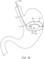
- FIG. 1A illustrates schematic block diagram of a fluid fillable balloon device 100; in particular, it illustrates a gastric balloon device assembly 100.
- FIG. 1B is an illustration of device 100 in place in a patient's stomach.
- the device generally comprises two states of interest: a pre-deployment or uninflated configuration and a deployed, inflated or active configuration; the deployed configuration is shown.
- the device is inflated with a fluid.
- the fluid can be delivered through a tube 110 also referred to herein as a catheter or conduit, wherein the tube may pass through a lumen in the wall of the balloon device or is coupled to a fluid path 112 between the exterior and the interior of the balloon device.
- the fluid can be delivered using any type of device that can deliver fluid.
- a wall 102 of the balloon 100 is fabricated from a thin film material such as, for example, polyurethane.
- the tube 110 comprises a balloon end or internal section 110A that extends through fluid path 112 into the central enclosed space or reservoir 104 of device 100.
- internal section 110A stops before entering the reservoir or is just adjacent to the reservoir 104.
- the conduit 110 is removed from the device once inflation is completed. When the conduit is removed, fluid path 112 must be sealed to prevent the fluid from leaking out through fluid path 112 from reservoir 104. As shown schematically in FIG. 1A , sealing is accomplished by fill valve, which may comprise an internal section 113B, an external section 113A, or a combination of both.
- elements of the fill valve 113 may have components installed inside conduit 110 as well as in fluid path 112.
- a gastric balloon device assembly 100 further comprise a fluid release valve 126.
- release valve 126 is independent from fill valve 113.
- release valve 126 may be combined, at least in part, with fill valve 113.
- release valve 126 reverses the operation of the sealing mechanism of fill valve 113.
- the fluid path itself serves as the fill valve, wherein the fluid path itself closes down to prevent fluid from escaping from reservoir 104.
- the fluid path is sealed by an automatic-sealing catheter assembly 10, which is a separate valve mechanism installed in the fluid path or in a portion of the conduit left behind in the fluid path when the main length of the conduit is withdrawn from the patient's body.
- FIG. 2A illustrates a partial cut-away view of one variation of the device 100 in the region of fill valve as it might appear within a patient's stomach, ready to be inflated.
- the fill valve is an automatic-sealing catheter assembly (ASCA) 10.
- the variation shown in FIG. 2A includes a catheter 110 that extends from interior section 110A to outside of device 100, typically extending far enough to reach the exterior of the patient, where the balloon thin film wall 102 defines the division between the interior and the exterior of the device.
- FIG. 2B is a close up cutaway view of the ASCA 10 of FIG. 2A .
- the assembly comprises the internal section 110A of catheter 110, the end of which has been sealed shut with a plug 120, in this variation by a toothed plug 120, during assembly.
- the plug has one or more circumferential, or partially circumferential, teeth or projections 115 which create rings or bulges 116 that cause an increased diameter on the exterior of internal section 110A.
- the circumferential projections 115 also work to lock plug 120 into section 110A substantially permanently, although glue, welding, or other bonding approaches could be used to lock a plug into section 110A.
- the catheter further comprises one or more side-wall openings or fill ports 130, where the variation with one fill port is show in the figures, wherein the fill ports are disposed to be clear from plug 120 to allow filling fluid coming through the catheter to freely enter the balloon.
- a catheter jacket 210 has been inserted through a section of balloon wall 102 from the exterior of the balloon and is held in place by pinching balloon wall 102 between the exterior of catheter jacket 210 and the interior of a balloon wall anchor 310.
- the catheter further comprises a weakened section 150 designed to define where and with what tension the catheter will tear apart.
- section 150 is a slit extending part way across conduit 110.
- FIG 3A illustrates another variation of ASCA 10.
- the toothed plug has been replaced with a spherical plug 125, for example a ball bearing.
- a retaining ring 410 has been added to reinforce wall anchor 310.
- An exploded, cross-sectional view of the ASCA 10 of FIG 3A is illustrated in FIG 3B for clarity.
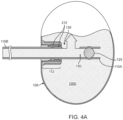
- FIG. 4A illustrates an example of the automatic-sealing behavior of the catheter assembly of FIG 3 .
- FIG. 4A illustrates ASCA 10 as fluid enters a balloon device 100.
- balloon 100 is inflated by injecting a fluid 1000 at a catheter fill end 110B.
- the fluid travels the length of the catheter and exits the catheter through a catheter fill port 130 disposed proximate or, in close proximity to, a catheter balloon end 110A, where the catheter balloon end 110A is intended to be inserted far enough into the balloon such that the fill port 130 is completely unobstructed by the other components of the variation of ASCA 10.
- FIG 4B illustrates a partially withdrawn catheter 110 in a sealing position.
- catheter 110 has been pulled into catheter jacket 210 until it moves plug 125 between the engagement elements 212 built into the inner surface of jacket 210.
- catheter 110 is secured in the sealing position when catheter wall bulges 116 formed by plug 125 abut engagement elements 212, which, in this variation, are ridges in the inside of catheter jacket 210.
- the fill port 130 is no longer in fluid communication with the interior of the balloon and the exterior of the catheter is compressed between the internal ridges and the plug, in this case operating like an o-ring, effectively sealing the catheter assembly.
- any further increase in axial tension on the catheter are applied to tear the catheter to allow the majority of catheter 110 to be extracted from the patient while leaving catheter balloon end 110A in catheter jacket 210, as indicated in FIG. 4B .
- tear-away slit 150 shown in FIG. 3B ) creates a unique location at which the catheter will tear; additionally, by design, the force at which the catheter tears can be adjusted to any reasonable value by varying the depth or shape of slit 150.
- plug 120 can have just one ( FIG. 5B ), instead of two ( FIG. 5C ), circumferential teeth 115, or a plug shaft 122 can be smooth sided ( FIG 5A ).
- plug 120 can be a small ball bearing 125 ( FIG 5D ) or the plug can be a measured amount of hardening material, for example, glue 127 injected into the end of the catheter 110 ( FIG. 5F ) or the distinct plug can be replaced by simply sealing the balloon end of catheter 110 ( FIG. 5E ).
- plug 120 includes a shaft 122 that is generally smooth sided except for a bulbous protrusion 118 at its tip.
- plug 120 comprises plug shaft 122 and a plug head 121 wherein plug shaft 122 has a main diameter substantially equal to the interior diameter of catheter 110 while plug head 121 has a diameter larger than the internal diameter, IDc, of catheter 110 to facilitate insertion and/or removal of plug 120 from the catheter and, in some variations, plug head 121 has a diameter larger than the external diameter of catheter 110 to improve retention of the catheter balloon end 110A inside balloon jacket 210 as the major portion of the catheter is removed from the patient's body.
- the plug shaft 122 comprises one or more teeth 115 wherein the teeth are disposed to permit plug 120 to be inserted into catheter balloon end 110A with relatively little extra resistance but are shaped to dig into the relatively soft catheter material when force is exerted in the direction to extract plug 120 from catheter 110.
- the diameter of the teeth is, by design, selected to form localized expanded bands, rings, or bulges 116 around the exterior of catheter 110. The region having these expanded bands is the interference region, so-called because the region has a mechanical interference with the engagement elements in jacket 210.
- Plug 120 may be fabricated from any substantially incompressible, bio-compatible material. In one variation the plug is fabricated from stainless steel. In one variation in which a ball bearing is used as plug 120 the diameter of the ball bearing is designed to provide substantially the same functions as a toothed plug, that is, the diameter of the ball bearing is slightly larger than IDc, thus both plugging catheter 110 and forming one expanded band around the exterior of catheter 110.
- FIG. 6A illustrates a single fill port 130 in catheter 110, whose size is determined by the net port open area designed to fill the balloon without creating excessive backpressure or slow fill rates.
- FIG. 6B the single fill port replaced by two or more, possibly smaller, ports 130A. These two ports are shown as diametrically opposed but they may be located anywhere around catheter 110.
- port 130 can even be replaced by micro-drilled perforations 131, as shown in FIG 6C , in a band around the catheter 110, this latter approach maintains rotational symmetry of the structure of the catheter 110 while still providing the desired net open area in the catheter.
- Laser micro machining by a vendor such as Resonetics, 44 Simon St. Nashua, NH can be advantageously used to create these small, closely packed openings 131 in the catheter material.
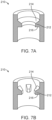
- FIG. 7 illustrates in cutaway variations of catheter jacket 210.
- jacket 210 comprises a rigid cylindrical tube.
- jacket 210 has an internal diameter smaller than the catheter's outer diameter by a small amount, say 0.010 inches.
- jacket 210 further comprises one or more raised engagement elements 212, wherein the elements 212 may be distinct bumps, knobs, or teeth, as shown in FIG. 7B , or they may be continuous ridges or rings as shown in FIG. 7A .
- engagement elements 212 reduce the internal clearance of the jacket to be less than catheter's 110 outer diameter to provide frictional engagement, or mechanical interference, between the jacket 210 and the interference region of catheter 110.
- the engagement element can gently dig into the exterior of catheter 110. This diametrical difference is preferably between 0.001 inches and 0.050 inches; more preferably between 0.005 inches and 0.020 inches; and most preferably between 0.006 and 0.010 inches
- one or more of these raised elements may be asymmetric relative to the axis of symmetry of jacket 210, that is, the interior edge 214 and the exterior edge 216 may have different slope angles.
- the interior edge 214 is sloped to facilitate pulling catheter balloon end 110A from the exterior side into jacket 210 to seal the ASCA while exterior edge 216 is more perpendicular to the interior wall of jacket 210 to inhibit, but not preventing, catheter balloon end 110A from moving inwardly after the rest of catheter 110 has been torn away.
- other engagement elements 212 may be configured to help form a fluid tight seal when plug 120 is pulled into jacket 210.
- the outermost (that is, closest to the exterior of balloon 100) engagement elements 212A have a small enough inner diameter to prevent plug 120 (shown as ball bearing 125 in FIG. 4B ) from being pulled out jacket 210 when catheter 110 is extracted, whilst innermost elements 212B prevent plug 120 from migrating back into balloon reservoir 104 once the plug is in the sealing position.
- Innermost elements 212B also help to form a fluid-tight seal by squeezing plug 125 against outermost elements 212A when there is a compressible section of catheter therebetween.
- engagement elements 212 are configured to compress and dig into catheter 110 to hold catheter balloon end 110A inside gastric device 100 under small, incidental extractive loads but not retain catheter balloon end 110A inside the gastric device under the larger, intentional extraction load used to detach the catheter from the device.
- the frictional force holding a prototypical polymeric catheter back from extraction generated by outermost or exterior engagement elements 212A of a compatibly designed jacket may be determined at the time of design to span a wide range.
- the elements that comprise the ASCA are intended to control the frictional/retention force that holds the catheter 110 in the ASCA during the deployment process.
- FIGS. 8A-8C there are three stages in the deployment process, where the maximum retaining force that holds the catheter within the device varies in each stage.
- the first stage that occurs after positioning the device in the stomach 20 is a filling stage, during which the medical caregiver begins to infuse fluid into the empty device 100 (or partially empty device).
- device 100 can be considered as a weighted mass at the end of the catheter 110.
- the weight of the balloon 100 increases from the weight of just the un-inflated thin film balloon.
- the filled balloon weight is approximately 500 grams.
- the filled device is at least partly supported by surrounding tissue or, in the case of a gastric balloon, by the contents of the stomach, which reduces the effective weight applied by the balloon on the catheter.
- the force that retains the catheter within the valve (the sliding resistance threshold or retention force "FR") must be greater than the effective weight (“WE”) or else the weight of the balloon could cause pre-mature detachment of the catheter or sealing of the valve.
- a second stage of the deployment process seals the ASCA. Closing this valve requires pulling balloon end 110A of catheter 110 into fluid path 112 such that the fill port 130 is withdrawn from the reservoir of the balloon 100.
- this stage of the process comprises pulling the catheter 110 in a proximal direction (e.g., towards the esophagus 22) until filled device 100 encounters resistance to motion against the esophageal sphincter 24. Once device 100 abuts sphincter 24, continued application of the proximal force increases the tension in catheter 100 until the tension is greater than, and overcomes, the FR, allowing the catheter internal end 110A to slide into fluid path 112 with a sliding resistance somewhat below the sliding resistance threshold.
- FC Closing force
- plug 120 reaches engagement elements 212A (not shown in FIG. 8A ) and cannot move any further.
- the majority of catheter 110 is disconnected from device 100 and removed from the patient's body. Only internal section 110A, which is part of ASCA 10, remains in device 100 after device deployment. With the device lodged against esophageal sphincter 24 the disconnection of catheter 110 is effected by pulling on the catheter with increasing force until the tension in catheter 110 exceeds a tear force, FT, which causes the catheter to separate at weakened section 150, in this variation a slit, where the depth of slit 150 has been designed to keep the tear force FT below a force, FE, that would damage the esophageal sphincter. Note that in some variations tear slit 150 is replaced by other means of weakening the catheter at the desired tear location to achieve a safe disconnection of catheter 110.
- FT tear force
- FIG. 7D illustrates the relationship between the internal diameter of an engagement element ("Barb ID") and the frictional force/resistance felt by a catheter, as measured for an exemplary embodiment of element 212A and catheter 110.
- FR is preferably, 0.25 lbf ⁇ FR ⁇ 1.6 lbf and more preferably 0.6 lbf ⁇ FR ⁇ 1.1 lbf. where 1.6 lbf was determined to be safely below FE for human patients. Further, 1.25 lbf ⁇ FT ⁇ 1.6 lbf. Note that FC is not a free design parameter because it is always equal to the FR of the specific as-built valve. (that is, the valve starts closing as soon as FC exceeds the threshold of FR).
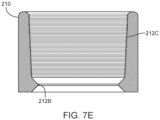
- FIG. 7E Another variation of a catheter jacket is illustrated in cutaway view in FIG. 7E .
- the distinct engagement elements of previous variations are replaced by closely spaced, tapered internal diameter ridges 212C. These ridges apply an increasingly tight grip on the catheter as catheter balloon end 110A is pulled further outwardly, whereas engagement elements 212A tend to grip the catheter with a constant force, independent of how far the catheter has been pulled.
- jacket 210 is affixed to a portion of the balloon wall material, either a free-standing patch or a relatively smooth portion of the actual balloon wall at, for example, a polar region of an oblate spheroid balloon.
- jacket 210 can be fabricated from a short piece of polymer tubing such as polyurethane, which is compatible with welding or gluing into an equatorial seam between two halves of a polymer, for example polyurethane, balloon.
- jacket 210 may be held in place by a balloon wall anchor 310.
- the thin film of material (either in the form of a section of the balloon wall 102 or a separate patch of material) is pinched between catheter jacket 210 and balloon wall anchor 310, locking catheter jacket 210 in place in the balloon wall.
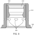
- anchor 310 may comprise one or more internal rings or teeth 320 to lock jacket 210 in place.
- anchor 310 comprises an inward-facing lip 315 which prevents catheter jacket 210 from entering the interior of the balloon device.
- anchor 310 comprises inward facing nubs 320 that are shaped to allow jacket 210 to slide over them when being inserted from the exterior side of the balloon but which lock it in place once the end of the jacket passes the edge of the nubs. Additionally, some variations of anchor 310 comprise a flared exterior facing end 330, as shown in FIGS. 2B and 3A . Flaring this end of wall anchor 310 provides a smooth and expanded contact surface between the anchor and the thin-film wall material, reducing the probability of tearing the wall material. In some variations anchor 310 is fabricated from polymer material to reduce the probability of damage to the thin film wall material 102, which is sandwiched between jacket 210 and anchor 310.
- retaining ring 410 is installed over balloon wall anchor 310.
- retaining ring 410 comprises a thin walled, stiff cylindrical tube with a close inner diameter-to-wall anchor outer diameter tolerance designed to capture the thin film wall material in a press fit.
- the retaining ring provides the creep resistance and stiffness normally found in a metal wall anchor.
- An advantage of this variation is that a metal catheter jacket, for example stainless steel, can be pressed through the region of thin-film wall material and up into the soft/compliant wall anchor without the force from the press fit causing the film to shear.
- the soft wall anchor acts as a cushion for the film between a stiff, metal catheter jacket and a stiff, metal retaining ring so that a strong press fit can be achieved.
- the ASCA can be fabricated on a separate patch of balloon-compatible material or assembled in situ in a wall of the balloon device.
- a process for fabricating the automatic-sealing catheter assembly typically comprises the following steps:
- the functions of the plug and fill port(s) can be combined by using a micro-check valve 123.
- a micro-check valve 123 For example, both axial and side exit micro-check valves are available from The Lee Company, 2 Pettipaug Road, PO Box 424, Westbrook, CT 06498. See, for example, Lee part number CCPI25100xxS, where xx is the cracking pressure.
- the check valve may be installed in catheter balloon end 110A as a direct replacement for plug 120, as illustrated in FIG. 10 , in which case the ASCA is similar to the variations described above, except there is no need for the catheter to comprise one or more fill ports.
- the fluid flows through the catheter and the (forward) pressure opens the check valve in the end of the catheter, allowing the fluid to enter reservoir.
- the check valve seals the end of the catheter.
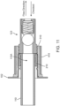
- FIG. 11 An alternative variation, shown in FIG. 11 , incorporates a micro-check valve 123 directly into the end of wall anchor 310 or retaining ring 410.
- the micro-check valve is part of the balloon device and the catheter is inserted into and held in catheter jacket 210 independently from the presence of a plug.
Landscapes
- Health & Medical Sciences (AREA)
- Heart & Thoracic Surgery (AREA)
- Life Sciences & Earth Sciences (AREA)
- Animal Behavior & Ethology (AREA)
- Veterinary Medicine (AREA)
- Public Health (AREA)
- Engineering & Computer Science (AREA)
- Biomedical Technology (AREA)
- General Health & Medical Sciences (AREA)
- Child & Adolescent Psychology (AREA)
- Orthopedic Medicine & Surgery (AREA)
- Vascular Medicine (AREA)
- Nursing (AREA)
- Obesity (AREA)
- Pulmonology (AREA)
- Anesthesiology (AREA)
- Hematology (AREA)
- Biophysics (AREA)
- Media Introduction/Drainage Providing Device (AREA)
Description
- The present invention generally relates to the field of balloon devices that occupy spaces within remote cavities and more particularly relates to the catheters/conduits used to inflate these devices with fluid.
- One example of balloon devices that occupy space in a remote cavity is a intragastric balloon for weight loss. According to 2010 World Health Organization data, 198 million Americans over the age of 15 are above target weight. Of these individuals, 89 million are considered overweight (25<Body Mass Index<30) and 109 million are considered obese (Body Mass Index >30). Worldwide, more than 1.4 billion
adults age 20 and over are overweight, and 500 million are obese. Obesity places patients at increased risk of numerous, potentially disablingconditions including type 2 diabetes, heart disease, stroke, gallbladder disease, and musculoskeletal disorders. Compared with healthy weight adults, obese adults are more than three times as likely to have been diagnosed with diabetes or high blood pressure. In the United States it is estimated that one in five cancer-related deaths may be attributable to obesity in female non-smokers and one in seven among male non-smokers (>= 50 years of age). On average, men and women who were obese at age 40 live 5.8 and 7.1 fewer years, respectively, than their healthy weight peers. - For the vast majority of the overweight and obese population for whom surgical obesity procedures are not appropriate, few efficacious and affordable interventions are currently available. Diet and exercise remain the front line approaches to obesity, however this approach has at best slowed the growth of the epidemic. To date, drug therapies have dose limiting side effects or have lacked meaningful long term efficacy.
- One less-invasive intervention that has begun to gain popularity is an intragastric balloon. Intragastric balloons in their uninflated state can be placed endoscopically or positioned using other methods and, once in place, are typically filled with a filling fluid through a thin catheter or conduit extending up the esophagus from the device in the stomach to an external fluid supply. This catheter is then removed from the device and extracted from the body through the esophagus. Upon removal of the catheter, the catheter fill system must seal the fluid communication between the interior of the device and the gastric environment to maintain the balloon in its filled state for the proscribed time.
- Such intragastric balloons to be expanded to occupy volume within the gastric space are known from, e.g.,
US 2014/0296903 A1 andUS 2017/0312111 A1 . - Several approaches to sealing the catheter system have been developed. For example, in
US20130012980 Brister describes the use of a septum, or rubber-like plug, through which a filling needle is disposed. Upon removal of the needle the rubber-like material elastically closes the puncture. While such a system is well-accepted for inflating athletic equipment such as footballs, it does require the hard, rubber-like septum to remain in the intragastric balloon for the life of the balloon. - Another approach for use in breast implants has been disclosed by Becker in
US2010/0110311 in which a filling tube comprising a soft, flexible hollow tube portion and a barbed, solid distal portion is pre-installed through a piece of "semi-rigid tube" that penetrates the balloon wall. The filling tube has an outer dimension that is slightly larger than the inner dimension of the semirigid tube and is stretchable longitudinally to reduce the outer diameter to facilitate passage through the passageway in the semirigid tube. Supposedly, the outer diameter of the solid portion of the filling tube can be reduced by said longitudinal stretching to allow the solid portion to be pulled into the semi-rigid tube. The solid portion then sealingly engages the semirigid tube upon relaxation thereof. The significant force that must be applied to the filling tube to pull the solid portion into the semirigid tube apparently requires that the semirigid tube is attached to the balloon wall by a reinforcing disk of material. However, this construction prevents the balloon described by Becker from being compacted into an ingestible capsule when uninflated. The inventor further notes that expansion of the solid portion upon relaxation is not adequate to ensure the solid portion remains in the semirigid portion and that "A key element in the ... invention resides in means such as a plurality of reverse barbs for preventing a plug valve from being dislodged... " - Commonly assigned publication
US20130218190 , discloses a self-sealing tunnel valve comprising two layers of thin film material through which a flexible fill catheter is disposed. The two layers tend to close together upon catheter withdrawal. This tunnel valve is extremely soft and flexible, making it suitable for compaction into an ingestible capsule and for long term residence in the stomach. - It would be desirable to have a self-sealing valve that is small and/or soft enough to be compacted into an ingestible capsule while also providing a distinct sealed condition.
- The present invention relates to devices and valve assemblies for remotely sealing an inflatable structure. For example, such devices can be used to occupying a space within a patient's body. In particular, the invention relates to catheter or conduit systems and methods for filling the devices and removing the catheter from the device and the patient's body without leakage of the filling fluid. In greater particularity, the present invention relates to catheter systems that automatically form a permanent seal for use in these space occupying devices. According to the present invention, a valve assembly as defined by
claim 1 and a balloon device as defined by claim 15 are provided. Preferred embodiments of the invention are laid down in dependent claims. - In one variation, the present devices include valve assemblies. Such valve assemblies can be used with a balloon device (or any expandable device) having a fluid port. In one example the valve assembly includes a jacket member having an elongated shape, an outer surface and an interior channel, the interior channel comprising an engagement member; a wall anchor positioned within the balloon device and adjacent to the fluid port, the wall anchor having an interior passage that receives the jacket member, where a portion of the balloon device adjacent to the fluid port extends into the interior passage of the wall anchor and is secured between the outer surface of the jacket member and the interior channel of the wall anchor; a conduit (or catheter/tube) extending through the interior channel of the jacket member, the conduit having a fill end and a balloon end, wherein the conduit and the interior channel are configured to have a sliding resistance therebetween; the conduit having an interference region at the balloon end positioned within the balloon device, the interference region having a locking profile that allows the interference region to become fixedly engaged within the interior channel when moved therein; a weakened section located between the fill end of the conduit and the interference region, wherein the weakened section has a reduced tensile strength less than a tensile strength of the conduit while permitting sliding of the conduit relative to the interior channel upon the application of a pulling force on the conduit without causing separation at the weakened section, wherein the reduced tensile strength
requires a tearing force to cause separation of the conduit at the weakened section; and a fill opening located on the conduit between the fill end and the interference region, the fill opening positioned within the balloon device such that fluid entering the fill end exits at the fill opening into the balloon, where the balloon end is occluded to prevent fluid from flowing therethrough, such that application of the pulling force that overcomes the sliding resistance causes movement the fill opening and the interference region into the jacket member to seal the balloon device. - Variation of the device can include a jacket member comprises an elongated cylindrical shape.
- In another variation, the balloon end of the conduit includes a cylindrical plug having an external shaft diameter equal to or greater than an interior diameter of the conduit. The cylindrical plug can include a plug head sized to prevent movement through the interior channel of the conduit. In another variation, the cylindrical plug comprises at least one tooth comprising a tapered shape that increases a force required to remove the plug from the conduit.
- A variation of the device can include a conduit that includes a spherical plug in the balloon end of the conduit, where an external diameter of the spherical plug is equal to or greater than an interior diameter of the conduit. The inter interference region can be adjacent to the balloon end.
- Variations of the conduit can include one or more weakened sections located between the fill end and the interference region.
- In another variation of the device, the interior channel of the jacket member includes at least one engaging element that reduces an interior diameter of the interior channel, wherein the interference region locks with the at least one engaging element to seal the interior channel of the jacket member.
- Variations of the wall anchor can comprises a flared end adjacent to the balloon device.
- The fill openings in the conduit can comprise a plurality of fill openings.
- In additional variations, the portion of the balloon device can extending into the interior passage of the wall anchor extends to at least a length of the jacket member.
- In variations of the device, a proximal face of the wall anchor is adjacent to but unconnected with a wall of the balloon device.
- In yet another variation, a friction fit between the conduit and the interior passage of the jacket member creates a resistance between the conduit and interior passage of the jacket member that permits movement of the balloon device upon pulling the conduit.
- The present invention also includes balloon device comprising one or more variations of the valve structure described herein.
- The present disclosure also includes methods for sealing and releasing a fluid-filled balloon tethered to a conduit within a remote cavity and accessible through a passage. For example, the method can include retaining an end of the conduit outside of the passage, where the conduit is coupled to the fluid-filled balloon through a closure assembly, and where the conduit comprises a weakened section; applying a first extractive force to the conduit to overcome a frictional resistance between the conduit and the closure assembly causing the conduit to slide within the closure assembly until an interference region of the conduit engages the closure assembly, wherein the first extractive force is insufficient to separate the conduit at the weakened section; applying a second sealing force to overcome a sealing resistance between the interference region and the closure assembly to seat the interference region within the closure assembly to form a seal therebetween, where the second sealing force is greater than the frictional resistance but is insufficient to separate the conduit at the weakened section; applying a third detachment force, the detachment force being greater than the second sealing force, wherein application of the detachment force causes separation of the conduit at the weakened section; and withdrawing the conduit from the passage.
- One variation of the method can further comprise applying a positioning force to the conduit, where the positioning force is less than the first extractive force and causes movement of the fluid-filled balloon and conduit within the remote cavity.
- The methods described herein can include positioning the fluid-filled balloon against an anatomic structure in or surrounding the remote cavity, wherein the anatomic structure applies a physical resistance against movement of the fluid-filled balloon.
- The resistance of the balloon member described herein can include a resistance against the balloon member when engaging a surface of the body cavity or a surface of the passage. Alternatively, or in combination, a fit between the conduit and the closure assembly can create a fluid seal at an interface of the conduit and the interior of the closure assembly. In another variation, a fit between the conduit and the closure assembly can creates a fluid seal at the closure assembly when the interference region is positioned within the interior of the closure assembly.
- Yet another variation of a method described in the present disclosure includes a method for filling a space in a remote cavity within a body and accessible through a passage. Such a method can include retaining an end of a conduit outside of the body; advancing the conduit and a balloon member into the remote cavity through the passage, where the conduit is coupled to the balloon member through a closure assembly, and where the conduit comprises a weakened section positioned within the balloon member; delivering a fluid through the conduit into the balloon member to increase a size of the balloon member; initially applying a proximal force on the conduit such that a resistance of the balloon member causes the conduit to slide relative to an interior of the closure assembly until an interference region on the conduit contacts the interior of the closure assembly to provide a locking resistance, increasing the initial proximal force on the conduit to overcome the locking resistance and lockingly seats the interference region within interior of the closure assembly and seals the closure assembly and the balloon; further increasing the proximal force on the conduit cause failure of the conduit at the weakened section such that a section of the conduit proximal to the weakened section separates from the closure assembly and balloon member; and retracting the section of the conduit from the passage.
- The present disclosure can also include catheter systems for use with fluid filled balloons for occupying a space within the patient's body. In one example such a medical device includes a liquid impermeable surface material forming a device body having an interior reservoir, the device body having a deployment profile and being expandable to an active profile upon receiving the liquid filler material within the interior reservoir; a fluid catheter comprising an extended section extending from the device to the exterior of the patient's body and a device section, the latter section passing through a fluid path, or catheter jacket, to provide a fluid filling material to the interior reservoir of the device body, where the catheter jacket is held in place in a wall of the device body by a balloon wall anchor, and where the extended section of the catheter is removable from the catheter jacket, such that upon removal of the extended portion of the catheter, the device section remains in the fluid path, which is thereby automatically closed to prevent liquid transfer to or from the patient's body.
- The valves described herein provide a secure seal upon removal of the catheter from the device where the seal can optionally be permanent. The valves can include a design and materials that permit packaging in a compact configuration. Variations of the valves can be soft enough to be left in a patient's stomach for extended period without irritation to the stomach. Additional variations of the valve can reduce incidents of damage to the valve or associated device during manufacture or storage. Additional variations of the valve allow for balancing of material properties to allow for improved catheter removal by stretching and tearing at a designed tension.
- The above and other features of the invention including various novel details of construction and combinations of parts, and other advantages, will now be more particularly described with reference to the accompanying drawings and pointed out in the claims. It will be understood that the particular method and device embodying the invention are shown by way of illustration and not as a limitation of the invention. The principles and features of this invention may be employed in various and numerous embodiments without departing from the scope of the invention.
- The foregoing and other objects, features and advantages of the methods, devices, and systems described herein will become apparent from the following description in conjunction with the accompanying drawings, in which reference characters refer to the same parts throughout the different views. The drawings are not necessarily to scale; emphasis has instead been placed upon illustrating the principles of the invention. Of the drawings:
-
FIGS. 1A is a schematic block diagram of a fluid fillable balloon device. -
FIG. 1B illustrates a fluid fillable balloon device being filled. -
FIG. 2A is a cutaway view of a variation of an Automatic-Sealing Catheter Assembly ("ASCA") installed in a thin film wall of a balloon device. -
FIGS. 2B is close up of the ASCA ofFIG. 2A -
FIG. 3A is a cutaway view of another variation of an ASCA. -
FIG. 3B is an exploded cutaway view of the variation of an ASCA ofFIG. 3A . -
FIG. 4A illustrates a variation of the ASCA while a balloon is being filled. -
FIG. 4B illustrates the ASCA ofFIG. 4A in its sealed configuration after a balloon is filled. -
FIG. 5A - 5G illustrate seven variations for a plug for an ASCA. -
FIG. 6A - 6C illustrate three variations of fill ports for an ASCA. -
FIG. 7A - 7C illustrates three variations of a wall a for an ASCA. -
FIG. 7D illustrates the relationship between the interior diameter of the exterior engagement element ofFIG. 7C and the frictional force holding a catheter in place. -
FIG. 7E is a cutaway view of another variation of a catheter jacket. -
FIGS. 8A to 8C illustrates an example of a deployment process of a device and valve assembly. -
FIG. 9 is a cutaway illustration of a balloon wall anchor for an ASCA. -
FIG. 10 illustrates an ASCA comprising a miniature check valve. -
FIG. 11 illustrates a second variation of an ASCA comprising a miniature check valve. - The following illustrations are examples of the invention described herein. It is contemplated that combinations of aspects of specific embodiments or combinations of the specific embodiments themselves are within the scope of this disclosure. The methods, devices, and systems described herein can be used to improve gastric balloon devices. However, the devices, methods, and systems of the present disclosure can also be useful in other medical and non-medical applications that require a fluid-filled device with a removable filling system.
-
FIG. 1A illustrates schematic block diagram of a fluidfillable balloon device 100; in particular, it illustrates a gastricballoon device assembly 100.FIG. 1B is an illustration ofdevice 100 in place in a patient's stomach. The device generally comprises two states of interest: a pre-deployment or uninflated configuration and a deployed, inflated or active configuration; the deployed configuration is shown. Generally, the device is inflated with a fluid. For example, the fluid can be delivered through atube 110 also referred to herein as a catheter or conduit, wherein the tube may pass through a lumen in the wall of the balloon device or is coupled to afluid path 112 between the exterior and the interior of the balloon device. In alternative variations, the fluid can be delivered using any type of device that can deliver fluid. In many balloon devices awall 102 of theballoon 100 is fabricated from a thin film material such as, for example, polyurethane. In some variations thetube 110 comprises a balloon end orinternal section 110A that extends throughfluid path 112 into the central enclosed space orreservoir 104 ofdevice 100. In other variationsinternal section 110A stops before entering the reservoir or is just adjacent to thereservoir 104. Theconduit 110 is removed from the device once inflation is completed. When the conduit is removed,fluid path 112 must be sealed to prevent the fluid from leaking out throughfluid path 112 fromreservoir 104. As shown schematically inFIG. 1A , sealing is accomplished by fill valve, which may comprise aninternal section 113B, anexternal section 113A, or a combination of both. In some variations, elements of the fill valve 113 may have components installed insideconduit 110 as well as influid path 112. - Some variations of a gastric
balloon device assembly 100 further comprise afluid release valve 126. In some variations releasevalve 126 is independent from fill valve 113. However, in some variations,release valve 126 may be combined, at least in part, with fill valve 113. In some variations,release valve 126 reverses the operation of the sealing mechanism of fill valve 113. - In some variations, the fluid path itself serves as the fill valve, wherein the fluid path itself closes down to prevent fluid from escaping from
reservoir 104. In other variations the fluid path is sealed by an automatic-sealingcatheter assembly 10, which is a separate valve mechanism installed in the fluid path or in a portion of the conduit left behind in the fluid path when the main length of the conduit is withdrawn from the patient's body.FIG. 2A illustrates a partial cut-away view of one variation of thedevice 100 in the region of fill valve as it might appear within a patient's stomach, ready to be inflated. In this variation, the fill valve is an automatic-sealing catheter assembly (ASCA) 10. The variation shown inFIG. 2A includes acatheter 110 that extends frominterior section 110A to outside ofdevice 100, typically extending far enough to reach the exterior of the patient, where the balloonthin film wall 102 defines the division between the interior and the exterior of the device. - .
FIG. 2B is a close up cutaway view of theASCA 10 ofFIG. 2A . The assembly comprises theinternal section 110A ofcatheter 110, the end of which has been sealed shut with aplug 120, in this variation by atoothed plug 120, during assembly. The plug has one or more circumferential, or partially circumferential, teeth orprojections 115 which create rings or bulges 116 that cause an increased diameter on the exterior ofinternal section 110A. Thecircumferential projections 115 also work to lockplug 120 intosection 110A substantially permanently, although glue, welding, or other bonding approaches could be used to lock a plug intosection 110A. The catheter further comprises one or more side-wall openings or fillports 130, where the variation with one fill port is show in the figures, wherein the fill ports are disposed to be clear fromplug 120 to allow filling fluid coming through the catheter to freely enter the balloon. In the illustrated variation, acatheter jacket 210 has been inserted through a section ofballoon wall 102 from the exterior of the balloon and is held in place by pinchingballoon wall 102 between the exterior ofcatheter jacket 210 and the interior of aballoon wall anchor 310. In the illustrated variation, the catheter further comprises a weakenedsection 150 designed to define where and with what tension the catheter will tear apart. In one variation,section 150 is a slit extending part way acrossconduit 110. - The cross-sectional view in
FIG 3A illustrates another variation ofASCA 10. In this variation, the toothed plug has been replaced with aspherical plug 125, for example a ball bearing. Also, in this variation a retainingring 410 has been added to reinforcewall anchor 310. An exploded, cross-sectional view of theASCA 10 ofFIG 3A is illustrated inFIG 3B for clarity. -
FIG. 4A illustrates an example of the automatic-sealing behavior of the catheter assembly ofFIG 3 .FIG. 4A illustratesASCA 10 as fluid enters aballoon device 100. As has been discussed above,balloon 100 is inflated by injecting a fluid 1000 at acatheter fill end 110B. The fluid travels the length of the catheter and exits the catheter through acatheter fill port 130 disposed proximate or, in close proximity to, acatheter balloon end 110A, where thecatheter balloon end 110A is intended to be inserted far enough into the balloon such that thefill port 130 is completely unobstructed by the other components of the variation ofASCA 10. Of course, if this condition is not met the balloon will still inflate if at least a portion of the port is unobstructed, albeit at a slower rate. After a proscribed volume of fluid has been injected into the balloon, or, alternatively, a proscribed back pressure of the fluid has been reached,catheter 110 is withdrawn from the patient. However, to maintain inflation of theballoon 100fluid path 1 12, which normally would allow two-way fluid flow, must prevent exit of the fluid to prevent deflation of the balloon. -
FIG 4B illustrates a partially withdrawncatheter 110 in a sealing position. As shown,catheter 110 has been pulled intocatheter jacket 210 until it movesplug 125 between theengagement elements 212 built into the inner surface ofjacket 210. In the illustrated variation,catheter 110 is secured in the sealing position when catheter wall bulges 116 formed byplug 125abut engagement elements 212, which, in this variation, are ridges in the inside ofcatheter jacket 210. In this configuration thefill port 130 is no longer in fluid communication with the interior of the balloon and the exterior of the catheter is compressed between the internal ridges and the plug, in this case operating like an o-ring, effectively sealing the catheter assembly. Once thecatheter balloon end 110A has been secured in the catheter jacket, any further increase in axial tension on the catheter are applied to tear the catheter to allow the majority ofcatheter 110 to be extracted from the patient while leavingcatheter balloon end 110A incatheter jacket 210, as indicated inFIG. 4B . By design, tear-away slit 150 (shown inFIG. 3B ) creates a unique location at which the catheter will tear; additionally, by design, the force at which the catheter tears can be adjusted to any reasonable value by varying the depth or shape ofslit 150. - Each of the elements of the ASCA can take multiple forms that effect the same results. For example, as shown in
FIG. 5A through 5g , plug 120 can have just one (FIG. 5B ), instead of two (FIG. 5C ),circumferential teeth 115, or aplug shaft 122 can be smooth sided (FIG 5A ). In other variations plug 120 can be a small ball bearing 125 (FIG 5D ) or the plug can be a measured amount of hardening material, for example,glue 127 injected into the end of the catheter 110 (FIG. 5F ) or the distinct plug can be replaced by simply sealing the balloon end of catheter 110 (FIG. 5E ). This seal can be effected by pinching theopen end 117 of the catheter and thermally sealing it closed, by gluing it closed, or by any other convenient means for eliminating a distinct plug component. In yet another variation, shown inFIG. 5G , plug 120 includes ashaft 122 that is generally smooth sided except for abulbous protrusion 118 at its tip. - In many variations plug 120 comprises
plug shaft 122 and aplug head 121 whereinplug shaft 122 has a main diameter substantially equal to the interior diameter ofcatheter 110 whileplug head 121 has a diameter larger than the internal diameter, IDc, ofcatheter 110 to facilitate insertion and/or removal ofplug 120 from the catheter and, in some variations, plughead 121 has a diameter larger than the external diameter ofcatheter 110 to improve retention of the catheter balloon end 110A insideballoon jacket 210 as the major portion of the catheter is removed from the patient's body. In some variations theplug shaft 122 comprises one ormore teeth 115 wherein the teeth are disposed to permitplug 120 to be inserted intocatheter balloon end 110A with relatively little extra resistance but are shaped to dig into the relatively soft catheter material when force is exerted in the direction to extractplug 120 fromcatheter 110. Furthermore, for reasons discussed below, the diameter of the teeth is, by design, selected to form localized expanded bands, rings, or bulges 116 around the exterior ofcatheter 110. The region having these expanded bands is the interference region, so-called because the region has a mechanical interference with the engagement elements injacket 210. - Plug 120 may be fabricated from any substantially incompressible, bio-compatible material. In one variation the plug is fabricated from stainless steel. In one variation in which a ball bearing is used as
plug 120 the diameter of the ball bearing is designed to provide substantially the same functions as a toothed plug, that is, the diameter of the ball bearing is slightly larger than IDc, thus both pluggingcatheter 110 and forming one expanded band around the exterior ofcatheter 110. - Similarly, as shown in
FIG. 6A through 6C , fillport 130 illustrated inFIG. 2 can be functionally replaced by other designs.FIG. 6A illustrates asingle fill port 130 incatheter 110, whose size is determined by the net port open area designed to fill the balloon without creating excessive backpressure or slow fill rates. InFIG. 6B the single fill port replaced by two or more, possibly smaller,ports 130A. These two ports are shown as diametrically opposed but they may be located anywhere aroundcatheter 110. Further,port 130 can even be replaced bymicro-drilled perforations 131, as shown inFIG 6C , in a band around thecatheter 110, this latter approach maintains rotational symmetry of the structure of thecatheter 110 while still providing the desired net open area in the catheter. Laser micro machining by a vendor such as Resonetics, 44 Simon St. Nashua, NH can be advantageously used to create these small, closelypacked openings 131 in the catheter material. - In the following, it will be considered that 1 inch = 25.4 mm.
FIG. 7 illustrates in cutaway variations ofcatheter jacket 210. In its most basic configuration, not illustrated,jacket 210 comprises a rigid cylindrical tube. In somevariations jacket 210 has an internal diameter smaller than the catheter's outer diameter by a small amount, say 0.010 inches. In many variations,jacket 210 further comprises one or more raisedengagement elements 212, wherein theelements 212 may be distinct bumps, knobs, or teeth, as shown inFIG. 7B , or they may be continuous ridges or rings as shown inFIG. 7A . In allcases engagement elements 212 reduce the internal clearance of the jacket to be less than catheter's 110 outer diameter to provide frictional engagement, or mechanical interference, between thejacket 210 and the interference region ofcatheter 110. In some cases, the engagement element can gently dig into the exterior ofcatheter 110. This diametrical difference is preferably between 0.001 inches and 0.050 inches; more preferably between 0.005 inches and 0.020 inches; and most preferably between 0.006 and 0.010 inches - In some variations one or more of these raised elements may be asymmetric relative to the axis of symmetry of
jacket 210, that is, theinterior edge 214 and theexterior edge 216 may have different slope angles. In one variation theinterior edge 214 is sloped to facilitate pulling catheter balloon end 110A from the exterior side intojacket 210 to seal the ASCA whileexterior edge 216 is more perpendicular to the interior wall ofjacket 210 to inhibit, but not preventing, catheter balloon end 110A from moving inwardly after the rest ofcatheter 110 has been torn away. - In other variations, as suggested in
FIG. 4B ,other engagement elements 212 may be configured to help form a fluid tight seal whenplug 120 is pulled intojacket 210. In some variations, as shown inFIG. 7C , there may be two or more sets of engagement elements. The outermost (that is, closest to the exterior of balloon 100)engagement elements 212A have a small enough inner diameter to prevent plug 120 (shown asball bearing 125 inFIG. 4B ) from being pulled outjacket 210 whencatheter 110 is extracted, whilstinnermost elements 212B preventplug 120 from migrating back intoballoon reservoir 104 once the plug is in the sealing position.Innermost elements 212B also help to form a fluid-tight seal by squeezingplug 125 againstoutermost elements 212A when there is a compressible section of catheter therebetween. - That is, some of
engagement elements 212 are configured to compress and dig intocatheter 110 to hold catheter balloon end 110A insidegastric device 100 under small, incidental extractive loads but not retain catheter balloon end 110A inside the gastric device under the larger, intentional extraction load used to detach the catheter from the device. As illustrated in the graph inFIG. 7D , the frictional force holding a prototypical polymeric catheter back from extraction generated by outermost orexterior engagement elements 212A of a compatibly designed jacket may be determined at the time of design to span a wide range. - In general, the elements that comprise the ASCA are intended to control the frictional/retention force that holds the
catheter 110 in the ASCA during the deployment process. As illustrated inFIGS. 8A-8C , for purposes of illustration, there are three stages in the deployment process, where the maximum retaining force that holds the catheter within the device varies in each stage. As shown inFIG. 8A , for a gastric balloon variation, the first stage that occurs after positioning the device in thestomach 20 is a filling stage, during which the medical caregiver begins to infuse fluid into the empty device 100 (or partially empty device). During this stage,device 100 can be considered as a weighted mass at the end of thecatheter 110. Asdevice 100 fills with fluid, especially when the fluid is a liquid, the weight of theballoon 100 increases from the weight of just the un-inflated thin film balloon. In one variation, the filled balloon weight ("WB") is approximately 500 grams. In some variations, the filled device is at least partly supported by surrounding tissue or, in the case of a gastric balloon, by the contents of the stomach, which reduces the effective weight applied by the balloon on the catheter. To keepdevice 100 from pulling away from, or sliding off,catheter 110 before the filling process is completed, the force that retains the catheter within the valve (the sliding resistance threshold or retention force "FR") must be greater than the effective weight ("WE") or else the weight of the balloon could cause pre-mature detachment of the catheter or sealing of the valve. - As shown in
FIG. 8B , a second stage of the deployment process seals the ASCA. Closing this valve requires pullingballoon end 110A ofcatheter 110 intofluid path 112 such that thefill port 130 is withdrawn from the reservoir of theballoon 100. As illustrated, this stage of the process comprises pulling thecatheter 110 in a proximal direction (e.g., towards the esophagus 22) until filleddevice 100 encounters resistance to motion against theesophageal sphincter 24. Oncedevice 100 abutssphincter 24, continued application of the proximal force increases the tension incatheter 100 until the tension is greater than, and overcomes, the FR, allowing the catheterinternal end 110A to slide intofluid path 112 with a sliding resistance somewhat below the sliding resistance threshold. This movement closes the valve. The force required to overcome FR is the called a "closing force" or "FC". In general, the FC is a "threshold" force, meaning that once FC overcomes FR, the force required to maintain movement of the catheter will be less than FC, since sliding friction is less than static friction/resistance. - As
catheter 110 is pulled intofluid path 112, plug 120 reachesengagement elements 212A (not shown inFIG. 8A ) and cannot move any further. - As illustrated in
FIG 8C , the majority ofcatheter 110 is disconnected fromdevice 100 and removed from the patient's body. Onlyinternal section 110A, which is part ofASCA 10, remains indevice 100 after device deployment. With the device lodged againstesophageal sphincter 24 the disconnection ofcatheter 110 is effected by pulling on the catheter with increasing force until the tension incatheter 110 exceeds a tear force, FT, which causes the catheter to separate atweakened section 150, in this variation a slit, where the depth ofslit 150 has been designed to keep the tear force FT below a force, FE, that would damage the esophageal sphincter. Note that in some variations tear slit 150 is replaced by other means of weakening the catheter at the desired tear location to achieve a safe disconnection ofcatheter 110. - The primary means of controlling the various forces are the material properties of the catheter material and the internal diameters and profiles of the internal features of
catheter jacket 210. For example,FIG. 7D illustrates the relationship between the internal diameter of an engagement element ("Barb ID") and the frictional force/resistance felt by a catheter, as measured for an exemplary embodiment ofelement 212A andcatheter 110. - During the design of
ASCA 10, several relationships must be considered. First, to prevent the catheter from moving during the balloon fill stage of deployment,


- In the following, it will be considered that 1 lbf is equal to 4.4482216 N. Based on experimental experience which determined both the WE and the FE, in one variation FR is preferably, 0.25 lbf < FR < 1.6 lbf and more preferably 0.6 lbf < FR < 1.1 lbf. where 1.6 lbf was determined to be safely below FE for human patients. Further, 1.25 lbf < FT< 1.6 lbf. Note that FC is not a free design parameter because it is always equal to the FR of the specific as-built valve. (that is, the valve starts closing as soon as FC exceeds the threshold of FR).
- The construction of the device shown above, with the various range of forces is especially useful in those situations such as a gastric device where deployment, filling, sealing, and detachment occurs remotely within the stomach. In such a case, it is desirable to close the valve and detach the conduit without supporting or holding the valve by supplementary means. Since the device is within the stomach, providing support to the valve or cutting the catheter would require a tool advanced through the esophagus causing the procedure to increase in complexity.
- Another variation of a catheter jacket is illustrated in cutaway view in
FIG. 7E . In this variation the distinct engagement elements of previous variations are replaced by closely spaced, tapered internal diameter ridges 212C. These ridges apply an increasingly tight grip on the catheter ascatheter balloon end 110A is pulled further outwardly, whereasengagement elements 212A tend to grip the catheter with a constant force, independent of how far the catheter has been pulled. - In some variations, as illustrated previously,
jacket 210 is affixed to a portion of the balloon wall material, either a free-standing patch or a relatively smooth portion of the actual balloon wall at, for example, a polar region of an oblate spheroid balloon. In other variations,jacket 210 can be fabricated from a short piece of polymer tubing such as polyurethane, which is compatible with welding or gluing into an equatorial seam between two halves of a polymer, for example polyurethane, balloon. - In some
variations jacket 210 may be held in place by aballoon wall anchor 310. In variations utilizing a balloon wall anchor, the thin film of material (either in the form of a section of theballoon wall 102 or a separate patch of material) is pinched betweencatheter jacket 210 andballoon wall anchor 310, lockingcatheter jacket 210 in place in the balloon wall. As shown inFIG. 9 ,anchor 310 may comprise one or more internal rings orteeth 320 to lockjacket 210 in place. In the variation shown inFIG. 9 ,anchor 310 comprises an inward-facinglip 315 which preventscatheter jacket 210 from entering the interior of the balloon device. Further,anchor 310 comprises inward facingnubs 320 that are shaped to allowjacket 210 to slide over them when being inserted from the exterior side of the balloon but which lock it in place once the end of the jacket passes the edge of the nubs. Additionally, some variations ofanchor 310 comprise a flaredexterior facing end 330, as shown inFIGS. 2B and3A . Flaring this end ofwall anchor 310 provides a smooth and expanded contact surface between the anchor and the thin-film wall material, reducing the probability of tearing the wall material. In some variations anchor 310 is fabricated from polymer material to reduce the probability of damage to the thinfilm wall material 102, which is sandwiched betweenjacket 210 andanchor 310. - As shown in
FIG. 3B , in some variations of the ASCA a retainingring 410 is installed overballoon wall anchor 310. In somevariations retaining ring 410 comprises a thin walled, stiff cylindrical tube with a close inner diameter-to-wall anchor outer diameter tolerance designed to capture the thin film wall material in a press fit. In variations with a soft anchor, the retaining ring provides the creep resistance and stiffness normally found in a metal wall anchor. An advantage of this variation is that a metal catheter jacket, for example stainless steel, can be pressed through the region of thin-film wall material and up into the soft/compliant wall anchor without the force from the press fit causing the film to shear. The soft wall anchor acts as a cushion for the film between a stiff, metal catheter jacket and a stiff, metal retaining ring so that a strong press fit can be achieved. - The ASCA can be fabricated on a separate patch of balloon-compatible material or assembled in situ in a wall of the balloon device. A process for fabricating the automatic-sealing catheter assembly typically comprises the following steps:
- 1) Identifying a region of thin-film material balloon wall suitable for installation. Such region is typically substantially flat and approximately 45 millimeters in diameter. In some applications in which the balloon is a highly oblate spheroid this region may be at one of the poles of the spheroid. In other variations the installation region may be on a separate patch of material known to be compatible with the thin film material of the balloon. In typical variations the patch of material is between .0025 and .005 inches thick. The patch of material will later be installed over a hole in the balloon device in a region that is typically substantially flat, such as at one of the poles of a highly oblate spheroidal balloon. In certain variations the installation region may be on a seam in the balloon wall.
- 2) Placing the thin film material in a fixture comprising two rigid plates, each of which have a central through hole with a diameter commensurate with the catheter jacket. The material region is sandwiched between the two plates and typically centered on the through hole.
- 3) Pushing the jacket up through the hole from a first side of the fixture, stretching the film over the jacket in the process. The first side of the fixture corresponds to the exterior of the balloon and defines an exterior side of the finished ASCA.
- 4) Pressing the wall anchor over the jacket and film from a second side of the fixture, captivating the film between the jacket and the wall anchor. The second side of the fixture corresponds to the interior of the balloon.
- 5) Removing the jacket-film-anchor subassembly from the rigid plate assembly.
- 6) Optionally pressing the retaining ring over the subassembly from what had been the second side of the fixture. The retaining ring should be bottomed out against the end of the wall anchor.
- 7) Separately, preparing the catheter balloon end. Typically, this preparation comprises:
- a. Creating one or more fill ports.
- b. Cutting one or more tear-away slits.
- 8) Inserting the prepared catheter balloon end into the subassembly from the exterior side of the ASCA, allowing the balloon end to project past the end of the rest of the subassembly by a convenient working distance but at least far enough to expose the fill port(s).
- 9) Inserting the plug into the open lumen of the catheter balloon end or, alternatively, sealing the open lumen of the catheter balloon end.
- 10) Withdrawing the catheter from the exterior side of the ASCA to eliminate excess catheter length on the interior side of the ASCA, leaving the fill port(s) exposed.
- In some variations of the ASCA the functions of the plug and fill port(s) can be combined by using a
micro-check valve 123. For example, both axial and side exit micro-check valves are available from The Lee Company, 2 Pettipaug Road, PO Box 424, Westbrook, CT 06498. See, for example, Lee part number CCPI25100xxS, where xx is the cracking pressure. In one of these variations the check valve may be installed incatheter balloon end 110A as a direct replacement forplug 120, as illustrated inFIG. 10 , in which case the ASCA is similar to the variations described above, except there is no need for the catheter to comprise one or more fill ports. Instead, the fluid flows through the catheter and the (forward) pressure opens the check valve in the end of the catheter, allowing the fluid to enter reservoir. When the forward pressure stops, the check valve seals the end of the catheter. When the balloon is adequately filled the catheter is removed as previously described but the catheter balloon end is retained in the catheter jacket by the "plug" formed by the micro-check valve. As before, extractive forces above the design level cause the catheter to tear away at tear away slit 150. - An alternative variation, shown in
FIG. 11 , incorporates amicro-check valve 123 directly into the end ofwall anchor 310 or retainingring 410. In this latter variation the micro-check valve is part of the balloon device and the catheter is inserted into and held incatheter jacket 210 independently from the presence of a plug. By the design ofcatheter jacket 210, small withdrawal forces are inadequate to pullcatheter 110 out ofcatheter jacket 210 but more significant withdrawal forces can pull the catheter from the catheter jacket. Such withdrawal can be accomplished with or without a tear slit.
Claims (15)
- A valve assembly for use with a balloon device 100 having a fluid port 130, the valve assembly comprising:a jacket member 210 having an outer surface and an interior channel;a wall anchor 310 configured to be positioned adjacent to the fluid port 130, the wall anchor 310 having an interior passage that receives the jacket member 210 to secure a portion of the balloon device 100 therebetween;a conduit 110 extending through the interior channel of the jacket member 210, the conduit 110 having a fill end 110B and a balloon end 110A, with a fill opening 130 located therebetween, wherein the balloon end 110A is occluded such that fluid 1000 can pass between the fill end 110B and the fill opening 130 wherein a portion of the conduit 110 and the interior channel are sized to create a sliding resistance therebetween;the conduit 110 having an interference region between the fill opening 130 and the balloon end 110A, such that when the conduit 110 moves within the interior channel to position the interference region into the interior channel the interference region becomes secured therein and seals the valve assembly by moving the fill opening 130 through or out of the interior channel; and characterised in that it furthers comprisesa weakened section 150 located between the fill end 110B of the conduit 110 and the interference region, wherein the weakened section 150 has a reduced tensile strength less than a tensile strength of the conduit 110 while permitting sliding of the conduit 110 relative to the interior channel upon application of a pulling force on the conduit 110 without causing separation at the weakened section 150, wherein the reduced tensile strength requires a tearing force to cause separation of the conduit 110 at the weakened section 150;a fill opening 130 located on the conduit 110 between the fill end 110B and the interference region, the fill opening 130 positioned within the balloon device 100 such that fluid 1000 entering the fill end 110B exits at the fill opening 130 into the balloon device 100, where the balloon end 110A is occluded to prevent fluid 1000 from flowing therethrough, such that application of the pulling force that overcomes sliding resistance causes movement the fill opening 130 andthe interference region into the jacket member 210 to seal the balloon device 100.
- The valve assembly of claim 1, where the jacket member 210 comprises an elongated cylindrical shape.
- The valve assembly of claim 1, where the balloon end 110A of the conduit 110 includes a cylindrical plug 120 having an external shaft diameter equal to or greater than an interior diameter of the conduit 110.
- The valve assembly of claim 3, where the cylindrical plug 120 comprises a plug head 121 sized to prevent movement through the interior channel of the conduit 110.
- The valve assembly of claim 3, wherein the cylindrical plug 120 comprises at least one tooth 115 comprising a tapered shape that increases a force required to remove the plug 120 from the conduit 110.
- The valve assembly of claim 1, wherein the conduit 110 includes a spherical plug 125 in the balloon end 110A of the conduit 110, where an external diameter of the spherical plug 125 is equal to or greater than an interior diameter of the conduit 110.
- The valve assembly of claim 1, wherein the interference region is adjacent to the balloon end 110A.
- The valve assembly of claim 1, wherein the weakened section 150 is located between the fill end 110B and the interference region.
- The valve assembly of claim 1, where the interior channel of the jacket member 210 includes at least one engaging element that reduces an interior diameter of the interior channel, wherein the interference region locks with the at least one engaging element to seal the interior channel of the jacket member 210.
- The valve assembly of claim 1, wherein the wall anchor 310 comprises a flared end adjacent to the balloon device 100.
- The valve assembly of claim 1, where the conduit 110 includes a plurality of fill openings 130A.
- The valve assembly of claim 1, wherein the portion of the balloon device 100 extending into the interior passage of the wall anchor 310 extends to at least a length of the jacket member 210.
- The valve assembly of claim 1, wherein a proximal face of the wall anchor 310 is adjacent to but unconnected with a wall of the balloon device 100.
- The valve assembly of claim 1, wherein a friction fit between the conduit 110 and the interior passage of the jacket member 210 creates a resistance between the conduit 110 and interior passage of the jacket member 210 that permits movement of the balloon device 100 upon pulling the conduit 110.
- A balloon device 100, comprising a balloon layer defining a reservoir 104, the reservoir 104 having a fluid port 130, and a valve assembly which is configured according to anyone of claims 1-14.
Priority Applications (1)
| Application Number | Priority Date | Filing Date | Title |
|---|---|---|---|
| EP24158123.0A EP4344724B1 (en) | 2018-02-26 | 2019-02-26 | Automatic-sealing balloon-filling catheter system |
Applications Claiming Priority (2)
| Application Number | Priority Date | Filing Date | Title |
|---|---|---|---|
| US201862635272P | 2018-02-26 | 2018-02-26 | |
| PCT/US2019/019630 WO2019165449A1 (en) | 2018-02-26 | 2019-02-26 | Automatic-sealing balloon-filling catheter system |
Related Child Applications (2)
| Application Number | Title | Priority Date | Filing Date |
|---|---|---|---|
| EP24158123.0A Division-Into EP4344724B1 (en) | 2018-02-26 | 2019-02-26 | Automatic-sealing balloon-filling catheter system |
| EP24158123.0A Division EP4344724B1 (en) | 2018-02-26 | 2019-02-26 | Automatic-sealing balloon-filling catheter system |
Publications (4)
| Publication Number | Publication Date |
|---|---|
| EP3755240A1 EP3755240A1 (en) | 2020-12-30 |
| EP3755240A4 EP3755240A4 (en) | 2021-12-08 |
| EP3755240B1 true EP3755240B1 (en) | 2024-03-27 |
| EP3755240C0 EP3755240C0 (en) | 2024-03-27 |
Family
ID=67685353
Family Applications (2)
| Application Number | Title | Priority Date | Filing Date |
|---|---|---|---|
| EP19756699.5A Active EP3755240B1 (en) | 2018-02-26 | 2019-02-26 | Automatic-sealing balloon-filling catheter system |
| EP24158123.0A Active EP4344724B1 (en) | 2018-02-26 | 2019-02-26 | Automatic-sealing balloon-filling catheter system |
Family Applications After (1)
| Application Number | Title | Priority Date | Filing Date |
|---|---|---|---|
| EP24158123.0A Active EP4344724B1 (en) | 2018-02-26 | 2019-02-26 | Automatic-sealing balloon-filling catheter system |
Country Status (4)
| Country | Link |
|---|---|
| US (5) | US10470908B2 (en) |
| EP (2) | EP3755240B1 (en) |
| ES (2) | ES3068095T3 (en) |
| WO (1) | WO2019165449A1 (en) |
Families Citing this family (10)
| Publication number | Priority date | Publication date | Assignee | Title |
|---|---|---|---|---|
| US10182932B2 (en) | 2012-02-21 | 2019-01-22 | Allurion Technologies, Inc. | Methods and devices for deploying and releasing a temporary implant within the body |
| IN2014DN07768A (en) | 2012-02-21 | 2015-05-15 | Allurion Technologies Inc | |
| ES3068095T3 (en) | 2018-02-26 | 2026-05-27 | Allurion Tech Llc | Self-sealing balloon filling catheter system |
| CN114376777B (en) | 2018-07-06 | 2024-02-02 | 安瑞仁科技公司 | Binary fluid control valve system |
| US11497900B2 (en) | 2018-12-13 | 2022-11-15 | Allurion Technologies, Inc. | Enhanced fluid delivery system |
| US20240050254A1 (en) * | 2019-09-20 | 2024-02-15 | Leonardo Salles De Almeida | Devices and method for bi-directional adjustment of intragastric balloons, and shut-off valve |
| CN111544175A (en) * | 2020-04-27 | 2020-08-18 | 王利 | slimming water bladder |
| CN115120298A (en) * | 2022-08-02 | 2022-09-30 | 为泰医疗器械(深圳)有限公司 | Double-cavity blocking balloon catheter and using method thereof |
| US12246163B2 (en) | 2023-04-12 | 2025-03-11 | Allurion Technologies, Inc. | Automatic-sealing balloon-filling catheter system |
| US12245962B2 (en) | 2023-04-12 | 2025-03-11 | Allurion Technologies, Inc. | Balloon sealing and fill valve |
Family Cites Families (147)
| Publication number | Priority date | Publication date | Assignee | Title |
|---|---|---|---|---|
| US2911988A (en) | 1956-01-24 | 1959-11-10 | Clarence J Ravn | Moisture releasable drain valve |
| US3586018A (en) | 1969-02-24 | 1971-06-22 | Thermia Verken Ab | Self-closing valve |
| US3638733A (en) | 1970-03-03 | 1972-02-01 | Kidde & Co Walter | Heat operated fire extinguisher |
| US3853116A (en) | 1971-06-21 | 1974-12-10 | Investors In Ventures Inc | Implant methods and devices for influencing body fluids |
| GB1577517A (en) | 1976-04-28 | 1980-10-22 | Ici Ltd | Method of thermoforming |
| US4133315A (en) | 1976-12-27 | 1979-01-09 | Berman Edward J | Method and apparatus for reducing obesity |
| US4253201A (en) | 1979-05-24 | 1981-03-03 | Ross David A | Prosthesis with self-sealing valve |
| DE2935631A1 (en) | 1979-09-04 | 1981-04-16 | Plate Bonn Gmbh, 5300 Bonn | MULTILAYER PLASTIC FILM, METHOD FOR THE PRODUCTION AND USE THEREOF |
| US4614188A (en) | 1980-08-15 | 1986-09-30 | Seymour Bazell | Balloon catheter |
| US4899747A (en) | 1981-12-10 | 1990-02-13 | Garren Lloyd R | Method and appartus for treating obesity |
| US4636213A (en) | 1985-01-24 | 1987-01-13 | Pakiam Anthony I | Implantable prosthesis |
| US4723547A (en) | 1985-05-07 | 1988-02-09 | C. R. Bard, Inc. | Anti-obesity balloon placement system |
| US4739758A (en) | 1986-05-19 | 1988-04-26 | Criticare Systems, Inc. | Apparatus for stomach cavity reduction |
| US4732188A (en) | 1987-06-15 | 1988-03-22 | Gt Development Corporation | Fuel tank cap with pressure/thermal relief |
| US4949756A (en) | 1988-08-31 | 1990-08-21 | Uresil Corporation | One-way valve |
| US4842007A (en) | 1988-09-08 | 1989-06-27 | Guard Associates, Inc. | Self-sealing valve for inflated bodies |
| US5018665A (en) | 1990-02-13 | 1991-05-28 | Hale Fire Pump Company | Thermal relief valve |
| US5092847A (en) | 1990-04-06 | 1992-03-03 | Sherwood Medical Company | Enteral feeding tube stylet |
| JP2514087Y2 (en) | 1990-05-25 | 1996-10-16 | 幸三 牧田 | Balloon with detachable double-sided check valve |
| US5222970A (en) | 1991-09-06 | 1993-06-29 | William A. Cook Australia Pty. Ltd. | Method of and system for mounting a vascular occlusion balloon on a delivery catheter |
| US5336123A (en) | 1992-04-08 | 1994-08-09 | Vonco Products, Inc. | Inflatable flexible pouch |
| US5348537A (en) | 1992-07-15 | 1994-09-20 | Advanced Cardiovascular Systems, Inc. | Catheter with intraluminal sealing element |
| US5482492A (en) | 1994-01-10 | 1996-01-09 | M & D Balloons, Inc. | Balloons and balloon valves |
| US5496203A (en) | 1994-03-25 | 1996-03-05 | Murray; Robert H. | Balloon valve assembly |
| US5507808A (en) | 1994-10-26 | 1996-04-16 | Becker; Hilton | Filling tube and seal construction |
| US5632297A (en) | 1995-09-26 | 1997-05-27 | Amcast Industrial Corporation | Piston-type thermally or pressure activated relief device |
| US5884625A (en) | 1996-07-09 | 1999-03-23 | Hart; William T. | Oral appliance for delivering gas to the retroglossal area |
| DE19831698C2 (en) | 1998-07-15 | 2000-08-31 | Caremed Medical Produkte Ag | Check valve, in particular for an implantable artificial bladder |
| US6129751A (en) | 1998-07-28 | 2000-10-10 | Intermedics Inc. | Cardiac lead with active fixation and biocompatible lubricant |
| AUPP550098A0 (en) | 1998-08-26 | 1998-09-17 | Microcatheters Pty Ltd | Catheter guide |
| US6162251A (en) | 1999-05-25 | 2000-12-19 | Novamed Medical Products Manufacturing, Inc. | Saline implant having single valve with primary and secondary closures |
| US6453907B1 (en) | 1999-08-12 | 2002-09-24 | Obtech Medical Ag | Food intake restriction with energy transfer device |
| US20040101540A1 (en) | 1999-09-01 | 2004-05-27 | John Cooker | Oral delivery system and method for making same |
| US6367499B2 (en) | 2000-03-02 | 2002-04-09 | Hamai Industries Limited | Safety valve |
| FR2805986B1 (en) | 2000-03-13 | 2002-10-11 | Districlass Madical | INTRA-GASTRIC DEVICE WITH VARIABLE VOLUME |
| US6682473B1 (en) | 2000-04-14 | 2004-01-27 | Solace Therapeutics, Inc. | Devices and methods for attenuation of pressure waves in the body |
| US6375972B1 (en) | 2000-04-26 | 2002-04-23 | Control Delivery Systems, Inc. | Sustained release drug delivery devices, methods of use, and methods of manufacturing thereof |
| US6663648B1 (en) | 2000-06-15 | 2003-12-16 | Cordis Corporation | Balloon catheter with floating stiffener, and procedure |
| US7837720B2 (en) | 2000-06-20 | 2010-11-23 | Boston Scientific Corporation | Apparatus for treatment of tissue adjacent a bodily conduit with a gene or drug-coated compression balloon |
| US6460541B1 (en) | 2000-11-07 | 2002-10-08 | Polyzen, Inc. | Heat-sealed inflatable article, and method of making the same |
| US6814097B2 (en) | 2001-03-20 | 2004-11-09 | Teleflex Gfi Control Systems L.P. | Pressure relief device |
| US6537247B2 (en) | 2001-06-04 | 2003-03-25 | Donald T. Shannon | Shrouded strain relief medical balloon device and method of use |
| US6644336B2 (en) | 2001-06-12 | 2003-11-11 | Oil States Industries, Inc. | Method and apparatus for automatic shutoff of a valve when a substance is present in a flow of fluid |
| US6939292B2 (en) | 2001-06-20 | 2005-09-06 | Olympus Corporation | Capsule type endoscope |
| US7160258B2 (en) | 2001-06-26 | 2007-01-09 | Entrack, Inc. | Capsule and method for treating or diagnosing the intestinal tract |
| US20040146559A1 (en) | 2002-09-28 | 2004-07-29 | Sowden Harry S. | Dosage forms having an inner core and outer shell with different shapes |
| US6712832B2 (en) | 2001-10-15 | 2004-03-30 | Tilak M. Shah | Low-pressure medical balloons and method of making same |
| TW555029U (en) | 2001-12-12 | 2003-09-21 | Shi-Guang Weng | Multi-purpose temperature control safety plug |
| US6733512B2 (en) | 2002-03-07 | 2004-05-11 | Mcghan Jim J. | Self-deflating intragastric balloon |
| US7169134B2 (en) | 2002-03-26 | 2007-01-30 | Ultradent Products, Inc. | Apparatus with rotatable valve syringe |
| US7485093B2 (en) | 2002-04-25 | 2009-02-03 | Given Imaging Ltd. | Device and method for in-vivo sensing |
| US6981978B2 (en) | 2002-08-30 | 2006-01-03 | Satiety, Inc. | Methods and devices for maintaining a space occupying device in a relatively fixed location within a stomach |
| US9060844B2 (en) | 2002-11-01 | 2015-06-23 | Valentx, Inc. | Apparatus and methods for treatment of morbid obesity |
| WO2004056343A1 (en) | 2002-12-19 | 2004-07-08 | Polymorfix, Inc. | Ingestible formulations for transient, noninvasive reduction of gastric volume |
| DK174883B1 (en) | 2003-02-27 | 2004-01-19 | Unomedical As | Disposable urine bag for collecting urine |
| JP3820483B2 (en) | 2003-03-03 | 2006-09-13 | 株式会社フジキン | safety valve |
| US6981980B2 (en) | 2003-03-19 | 2006-01-03 | Phagia Technology | Self-inflating intragastric volume-occupying device |
| US20060058829A1 (en) | 2003-03-19 | 2006-03-16 | Sampson Douglas C | Intragastric volume-occupying device |
| AU2003245593B2 (en) | 2003-06-20 | 2010-06-03 | Apollo Endosurgery, Inc. | Two-way slit valve |
| US8048169B2 (en) | 2003-07-28 | 2011-11-01 | Baronova, Inc. | Pyloric valve obstructing devices and methods |
| US9498366B2 (en) | 2003-07-28 | 2016-11-22 | Baronova, Inc. | Devices and methods for pyloric anchoring |
| US7951121B2 (en) | 2003-07-30 | 2011-05-31 | Navilyst Medical, Inc. | Pressure actuated valve with improved slit configuration |
| US20060004323A1 (en) | 2004-04-21 | 2006-01-05 | Exploramed Nc1, Inc. | Apparatus and methods for dilating and modifying ostia of paranasal sinuses and other intranasal or paranasal structures |
| ES2562236T3 (en) | 2004-08-13 | 2016-03-03 | Obalon Therapeutics, Inc. | Intragastric volume occupation device |
| US20080275569A1 (en) | 2004-09-16 | 2008-11-06 | Evera Medical, Inc | Tissue Augmentation Device |
| US7641688B2 (en) | 2004-09-16 | 2010-01-05 | Evera Medical, Inc. | Tissue augmentation device |
| US20070078476A1 (en) | 2004-10-12 | 2007-04-05 | Hull Wendell C Sr | Overweight control apparatuses for insertion into the stomach |
| CA2585582C (en) | 2004-11-11 | 2010-08-10 | Kabushiki Kaisha Kawasaki Precision Machinery | Safety valve device |
| US20080269555A1 (en) | 2005-02-24 | 2008-10-30 | Compagnie Europeenne D'etude Et De Recherche De Di Spositifs Pour L'lmplantation Par Laparoscopie | Intragastric Balloon With Extraction Reinforcement |
| US20060222705A1 (en) | 2005-03-31 | 2006-10-05 | Flanner Henry H | Pharmaceutical tablet and apparatus and method for making |
| ES2351762T3 (en) | 2005-06-01 | 2011-02-10 | Compagnie Européenne D' Etude Et De Recherche De Dispositifs Pour L'implantation Par Laparoscopie | INTRAGASTRIC BALL PROVIDED WITH A VALVE CONTAINING A GEL AND KIT. |
| US20070010791A1 (en) | 2005-07-07 | 2007-01-11 | Bristol-Myers Squibb Company | Valve for inflatable chamber of medical device |
| EP1948077B1 (en) | 2005-10-31 | 2015-12-23 | ReShape Medical Corporation | Intragastric space filler |
| US20110112383A1 (en) | 2005-11-08 | 2011-05-12 | Plensat, Inc | Devices, systems and methods for treatment of eating disorders |
| US20070207199A1 (en) | 2005-12-28 | 2007-09-06 | Sogin Stephen J | Appetite suppression device |
| FR2897529B1 (en) | 2006-02-17 | 2008-10-31 | Cie Euro Etude Rech Paroscopie | INTRA-GASTRIC BALLOON WITH SHAPE MEMORY |
| US8398668B2 (en) | 2006-04-19 | 2013-03-19 | Vibrynt, Inc. | Devices and methods for treatment of obesity |
| US7740023B2 (en) | 2006-08-18 | 2010-06-22 | Restaurant Technologies, Inc. | Check valve assemblies and related methods |
| EP2061397B1 (en) | 2006-09-02 | 2015-01-07 | Barosense, Inc. | Intestinal sleeves and associated deployment systems |
| ES2322494T3 (en) | 2006-11-06 | 2009-06-22 | Job Lizenz Gmbh | SECURITY VALVE FOR A HIGH PRESSURE GAS DEPOSIT. |
| US20080183128A1 (en) | 2007-01-24 | 2008-07-31 | John Morriss | Methods, devices and systems for treatment and/or diagnosis of disorders of the ear, nose and throat |
| US8585676B2 (en) | 2007-02-05 | 2013-11-19 | Polyzen Inc. | Multi-lumen lay-flat tubing, catheter articles comprising same, and method of manufacture thereof |
| JP5259966B2 (en) | 2007-03-26 | 2013-08-07 | 株式会社ジェイ・エム・エス | Oral pressure measuring balloon and method for manufacturing the same |
| US8226602B2 (en) | 2007-03-30 | 2012-07-24 | Reshape Medical, Inc. | Intragastric balloon system and therapeutic processes and products |
| US20080249635A1 (en) | 2007-04-05 | 2008-10-09 | Barry Weitzner | Gastric filler devices for obesity therapy |
| US20080306441A1 (en) | 2007-04-10 | 2008-12-11 | Wilson-Cook Medical Inc. | Non-buckling balloon catheter with spring loaded floating flexible tip |
| US20080255601A1 (en) | 2007-04-13 | 2008-10-16 | Allergan, Inc. | Apparatus and method for remote deflation of intragastric balloon |
| US7976497B2 (en) | 2007-09-25 | 2011-07-12 | Polyzen Inc. | Multi-layer film welded articulated balloon |
| JP2011500278A (en) | 2007-10-23 | 2011-01-06 | アラーガン、インコーポレイテッド | Remote contraction of intragastric balloon |
| WO2009059803A1 (en) | 2007-11-09 | 2009-05-14 | Venera Khafizova | Externally inflatable gastric balloon device |
| WO2009059802A1 (en) | 2007-11-09 | 2009-05-14 | Venera Khafizova | Self-deflating gastric balloon device |
| WO2009086119A2 (en) | 2007-12-20 | 2009-07-09 | 7L, Llc | Swallowable self-expanding gastric space occupying device |
| US20090259246A1 (en) | 2008-04-14 | 2009-10-15 | Sherif Eskaros | Intragastric Volume-Occupying Device |
| US8377128B2 (en) | 2008-04-28 | 2013-02-19 | Allergan, Inc. | Flush patch for elastomeric implant shell |
| US20090275919A1 (en) | 2008-05-01 | 2009-11-05 | Edwards Lifesciences Corporation | Balloon Deployment Device and Method |
| US7971798B2 (en) | 2008-05-07 | 2011-07-05 | GM Global Technology Operations LLC | Resettable thermal pressure relief device |
| US20090299401A1 (en) | 2008-06-02 | 2009-12-03 | Loma Vista Medical, Inc. | Inflatable medical devices |
| US20100062057A1 (en) | 2008-09-10 | 2010-03-11 | Pronova BioPharma Norge AS. | Formulation |
| US9072583B2 (en) | 2008-10-16 | 2015-07-07 | Obalon Therapeutics, Inc. | Intragastric volume-occupying device and method for fabricating same |
| US20100110311A1 (en) | 2008-10-30 | 2010-05-06 | Samsung Electronics Co., Ltd. | Method and system for adjusting a presentation of image data |
| US20100114311A1 (en) | 2008-11-05 | 2010-05-06 | Hilton Becker | Multi-Lumen Breast Prothesis and Improved Valve Assembly Therefor |
| US9913964B2 (en) | 2008-12-29 | 2018-03-13 | Acclarnet, Inc. | System and method for dilating an airway stenosis |
| US20100246165A1 (en) | 2009-03-31 | 2010-09-30 | Diaz Edmundo B | Invisible and/ or non-invisible designed inflatables combined with electric black ultra-violet lights and inflator nozzle fixture accessories |
| US20110004236A1 (en) | 2009-07-01 | 2011-01-06 | E2 Llc | Systems and Methods for Treating Obesity and Type 2 Diabetes |
| US8608642B2 (en) | 2010-02-25 | 2013-12-17 | Ethicon Endo-Surgery, Inc. | Methods and devices for treating morbid obesity using hydrogel |
| US20110275882A1 (en) | 2010-05-05 | 2011-11-10 | Syncardia Systems, Inc | Valve for ventricular assist device |
| CA2793916C (en) | 2010-05-10 | 2016-10-25 | Edwards Lifesciences Corporation | Prosthetic heart valve |
| EP3552655B1 (en) | 2010-07-13 | 2020-12-23 | Loma Vista Medical, Inc. | Inflatable medical devices |
| US8870966B2 (en) | 2010-10-18 | 2014-10-28 | Apollo Endosurgery, Inc. | Intragastric balloon for treating obesity |
| US20120141544A1 (en) | 2010-12-03 | 2012-06-07 | Fuisz Richard C | Solid Dosage Form That Promotes Reliable Oral, Esophageal and GI Transit |
| US8383135B2 (en) | 2010-12-03 | 2013-02-26 | Richard C. Fuisz | Solid dosage form that promotes reliable oral, esophageal and GI transit |
| US9572698B2 (en) | 2011-01-17 | 2017-02-21 | Metactive Medical, Inc. | Ballstent device and methods of use |
| CN201977967U (en) | 2011-01-18 | 2011-09-21 | 郭加 | Intragastric ball packing device for losing weight |
| DK2665512T3 (en) | 2011-01-21 | 2016-10-10 | Obalon Therapeutics Inc | Intragastric device |
| US8292911B2 (en) | 2011-01-21 | 2012-10-23 | Obalon Therapeutics, Inc. | Intragastric device |
| US8647358B2 (en) | 2011-01-21 | 2014-02-11 | Obalon Therapeutics Inc. | Intragastric device |
| US8202291B1 (en) | 2011-01-21 | 2012-06-19 | Obalon Therapeutics, Inc. | Intragastric device |
| US20120273050A1 (en) | 2011-04-28 | 2012-11-01 | K&N Innovations, LLC | Automatic Shutoff Drain |
| US8183227B1 (en) | 2011-07-07 | 2012-05-22 | Chemo S. A. France | Compositions, kits and methods for nutrition supplementation |
| US8974483B2 (en) | 2012-02-21 | 2015-03-10 | Allurion Technologies, Inc. | Methods and devices for deploying and releasing a temporary implant within the body |
| US10182932B2 (en) | 2012-02-21 | 2019-01-22 | Allurion Technologies, Inc. | Methods and devices for deploying and releasing a temporary implant within the body |
| WO2014074625A1 (en) | 2012-02-21 | 2014-05-15 | Allurion Technologies, Inc. | Anatomically adapted ingestible delivery systems and methods |
| IN2014DN07768A (en) | 2012-02-21 | 2015-05-15 | Allurion Technologies Inc | |
| EP2830548B1 (en) | 2012-03-29 | 2019-09-18 | Trudell Medical International | Oral device with bolus simulator and method of use thereof |
| WO2014040064A1 (en) * | 2012-09-10 | 2014-03-13 | Boston Scientific Scimed, Inc. | Catheter with releasable balloon and related methods |
| US8628571B1 (en) | 2012-11-13 | 2014-01-14 | Mitraltech Ltd. | Percutaneously-deliverable mechanical valve |
| US9713578B2 (en) | 2012-12-20 | 2017-07-25 | Sabry Gabriel | Feeding tube with inflatable balloon component |
| JP5973367B2 (en) | 2013-03-04 | 2016-08-23 | 川崎重工業株式会社 | Fusing type safety valve |
| CN106029013B (en) | 2013-11-01 | 2019-08-27 | 阿勒里恩科技公司 | Method and apparatus for deploying and releasing a temporary graft in the body |
| CN106456312A (en) | 2014-04-25 | 2017-02-22 | 克里提瓦思科医疗公司 | Magnetically activated arteriovenous access valve system and related methods |
| JP2016030000A (en) | 2014-07-28 | 2016-03-07 | 株式会社クローバージャパン | Carbonated spring generation device |
| US20160045719A1 (en) | 2014-08-15 | 2016-02-18 | Acclarent, Inc. | Shaft system for balloon dilation |
| US9822886B2 (en) | 2014-10-15 | 2017-11-21 | Baker Products, Ltd. | Temperature controlled purge valve with washer/O-ring seal stack |
| CN107530538B (en) | 2015-03-09 | 2020-10-02 | 阿勒里恩科技公司 | Method and apparatus for deploying and releasing a temporary implant in a body |
| AU2016232781B2 (en) | 2015-03-19 | 2017-11-02 | Prytime Medical Devices, Inc. | System for low-profile occlusion balloon catheter |
| GB2541221B (en) | 2015-08-12 | 2021-04-14 | Royal United Hospitals Bath Nhs Found Trust | Pinch valve for a urinary drainage system |
| US20170211715A1 (en) | 2016-01-21 | 2017-07-27 | GM Global Technology Operations LLC | Oil bypass valve with temporary spacer to provide initially opened fluid circuit |
| DE112017000675T5 (en) | 2016-02-05 | 2018-10-18 | Allurion Technologies, Inc. | Method of making devices for placing and releasing a temporary implant in the body |
| US10779980B2 (en) | 2016-04-27 | 2020-09-22 | Synerz Medical, Inc. | Intragastric device for treating obesity |
| CA2990479C (en) | 2016-06-02 | 2019-03-26 | Prytime Medical Devices, Inc. | System and method for low-profile occlusion balloon catheter |
| JP6222763B1 (en) | 2017-01-31 | 2017-11-01 | 日本ライフライン株式会社 | Balloon catheter |
| US20180311484A1 (en) | 2017-05-01 | 2018-11-01 | Allurion Technologies, Inc. | Method of fabrication for devices for deploying and releasing a temporary implant within the body |
| US10238516B1 (en) | 2017-11-01 | 2019-03-26 | Barix Medical Corp. | Simplified implantable gastric balloon system with self deflating timer |
| EP3720395B1 (en) | 2017-12-07 | 2024-05-22 | ReShape Lifesciences Inc. | Intragastric device with self-deflation |
| ES3068095T3 (en) | 2018-02-26 | 2026-05-27 | Allurion Tech Llc | Self-sealing balloon filling catheter system |
| CN114376777B (en) | 2018-07-06 | 2024-02-02 | 安瑞仁科技公司 | Binary fluid control valve system |
| US11497900B2 (en) | 2018-12-13 | 2022-11-15 | Allurion Technologies, Inc. | Enhanced fluid delivery system |
-
2019
- 2019-02-26 ES ES24158123T patent/ES3068095T3/en active Active
- 2019-02-26 EP EP19756699.5A patent/EP3755240B1/en active Active
- 2019-02-26 WO PCT/US2019/019630 patent/WO2019165449A1/en not_active Ceased
- 2019-02-26 EP EP24158123.0A patent/EP4344724B1/en active Active
- 2019-02-26 ES ES19756699T patent/ES2982266T3/en active Active
- 2019-02-26 US US16/286,321 patent/US10470908B2/en active Active
- 2019-09-05 US US16/562,055 patent/US10583024B2/en active Active
- 2019-09-05 US US16/562,021 patent/US10588768B2/en active Active
-
2020
- 2020-01-24 US US16/752,515 patent/US11559418B2/en active Active
-
2022
- 2022-12-20 US US18/068,907 patent/US12109138B2/en active Active
Also Published As
| Publication number | Publication date |
|---|---|
| US20200155335A1 (en) | 2020-05-21 |
| EP4344724C0 (en) | 2026-04-01 |
| WO2019165449A1 (en) | 2019-08-29 |
| US20190388258A1 (en) | 2019-12-26 |
| US10588768B2 (en) | 2020-03-17 |
| US11559418B2 (en) | 2023-01-24 |
| EP4344724A2 (en) | 2024-04-03 |
| US10470908B2 (en) | 2019-11-12 |
| ES3068095T3 (en) | 2026-05-27 |
| US12109138B2 (en) | 2024-10-08 |
| EP3755240A1 (en) | 2020-12-30 |
| EP4344724B1 (en) | 2026-04-01 |
| ES2982266T3 (en) | 2024-10-15 |
| US20190262157A1 (en) | 2019-08-29 |
| EP3755240A4 (en) | 2021-12-08 |
| US10583024B2 (en) | 2020-03-10 |
| US20230120118A1 (en) | 2023-04-20 |
| EP3755240C0 (en) | 2024-03-27 |
| EP4344724A3 (en) | 2024-08-21 |
| US20190388259A1 (en) | 2019-12-26 |
Similar Documents
| Publication | Publication Date | Title |
|---|---|---|
| US12109138B2 (en) | Automatic-sealing balloon-filling catheter system | |
| EP4295820B1 (en) | Binary fluid control valve system | |
| US4909785A (en) | Method for valving body fluids | |
| US20250345198A1 (en) | Methods and devices for deploying and releasing a temporary implant within the body | |
| US5112306A (en) | Method and apparatus for valving body fluids | |
| EP0886503B1 (en) | Filling tube and seal construction | |
| US20110295300A1 (en) | Intragastric treatment assembly | |
| US20120088962A1 (en) | Self-adjusting gastric band | |
| US12246163B2 (en) | Automatic-sealing balloon-filling catheter system | |
| US12245962B2 (en) | Balloon sealing and fill valve | |
| DE102012003034A1 (en) | Device for closing opening a large intestine or anus of patient and to continuously or intermittently drain or remove of stool, has inflatable balloon with annular structure, particularly located in inverted tube section | |
| CN121843667A (en) | Intra-urethral device | |
| EP0769931A1 (en) | An assembly and method for prevention of urinary incontinence in humans | |
| JP2017169806A (en) | Cervical canal treatment method and medical instrument for treating cervical canal |
Legal Events
| Date | Code | Title | Description |
|---|---|---|---|
| STAA | Information on the status of an ep patent application or granted ep patent |
Free format text: STATUS: THE INTERNATIONAL PUBLICATION HAS BEEN MADE |
|
| PUAI | Public reference made under article 153(3) epc to a published international application that has entered the european phase |
Free format text: ORIGINAL CODE: 0009012 |
|
| STAA | Information on the status of an ep patent application or granted ep patent |
Free format text: STATUS: REQUEST FOR EXAMINATION WAS MADE |
|
| 17P | Request for examination filed |
Effective date: 20200925 |
|
| AK | Designated contracting states |
Kind code of ref document: A1 Designated state(s): AL AT BE BG CH CY CZ DE DK EE ES FI FR GB GR HR HU IE IS IT LI LT LU LV MC MK MT NL NO PL PT RO RS SE SI SK SM TR |
|
| AX | Request for extension of the european patent |
Extension state: BA ME |
|
| DAV | Request for validation of the european patent (deleted) | ||
| DAX | Request for extension of the european patent (deleted) | ||
| A4 | Supplementary search report drawn up and despatched |
Effective date: 20211108 |
|
| RIC1 | Information provided on ipc code assigned before grant |
Ipc: A61M 29/02 20060101ALI20211102BHEP Ipc: A61M 29/00 20060101ALI20211102BHEP Ipc: A61M 25/00 20060101ALI20211102BHEP Ipc: A61F 5/00 20060101ALI20211102BHEP Ipc: A61B 17/00 20060101ALI20211102BHEP Ipc: A61B 17/12 20060101AFI20211102BHEP |
|
| STAA | Information on the status of an ep patent application or granted ep patent |
Free format text: STATUS: EXAMINATION IS IN PROGRESS |
|
| 17Q | First examination report despatched |
Effective date: 20230707 |
|
| GRAP | Despatch of communication of intention to grant a patent |
Free format text: ORIGINAL CODE: EPIDOSNIGR1 |
|
| STAA | Information on the status of an ep patent application or granted ep patent |
Free format text: STATUS: GRANT OF PATENT IS INTENDED |
|
| INTG | Intention to grant announced |
Effective date: 20231019 |
|
| GRAS | Grant fee paid |
Free format text: ORIGINAL CODE: EPIDOSNIGR3 |
|
| GRAA | (expected) grant |
Free format text: ORIGINAL CODE: 0009210 |
|
| STAA | Information on the status of an ep patent application or granted ep patent |
Free format text: STATUS: THE PATENT HAS BEEN GRANTED |
|
| AK | Designated contracting states |
Kind code of ref document: B1 Designated state(s): AL AT BE BG CH CY CZ DE DK EE ES FI FR GB GR HR HU IE IS IT LI LT LU LV MC MK MT NL NO PL PT RO RS SE SI SK SM TR |
|
| REG | Reference to a national code |
Ref country code: GB Ref legal event code: FG4D |
|
| REG | Reference to a national code |
Ref country code: CH Ref legal event code: EP |
|
| REG | Reference to a national code |
Ref country code: DE Ref legal event code: R096 Ref document number: 602019049049 Country of ref document: DE |
|
| REG | Reference to a national code |
Ref country code: IE Ref legal event code: FG4D |
|
| U01 | Request for unitary effect filed |
Effective date: 20240327 |
|
| U07 | Unitary effect registered |
Designated state(s): AT BE BG DE DK EE FI FR IT LT LU LV MT NL PT SE SI Effective date: 20240403 |
|
| RAP2 | Party data changed (patent owner data changed or rights of a patent transferred) |
Owner name: ALLURION TECHNOLOGIES, LLC |
|
| U1K | Transfer of rights of the unitary patent after the registration of the unitary effect |
Owner name: ALLURION TECHNOLOGIES, LLC; US |
|
| PG25 | Lapsed in a contracting state [announced via postgrant information from national office to epo] |
Ref country code: GR Free format text: LAPSE BECAUSE OF FAILURE TO SUBMIT A TRANSLATION OF THE DESCRIPTION OR TO PAY THE FEE WITHIN THE PRESCRIBED TIME-LIMIT Effective date: 20240628 |
|
| PG25 | Lapsed in a contracting state [announced via postgrant information from national office to epo] |
Ref country code: HR Free format text: LAPSE BECAUSE OF FAILURE TO SUBMIT A TRANSLATION OF THE DESCRIPTION OR TO PAY THE FEE WITHIN THE PRESCRIBED TIME-LIMIT Effective date: 20240327 Ref country code: RS Free format text: LAPSE BECAUSE OF FAILURE TO SUBMIT A TRANSLATION OF THE DESCRIPTION OR TO PAY THE FEE WITHIN THE PRESCRIBED TIME-LIMIT Effective date: 20240627 |
|
| PG25 | Lapsed in a contracting state [announced via postgrant information from national office to epo] |
Ref country code: RS Free format text: LAPSE BECAUSE OF FAILURE TO SUBMIT A TRANSLATION OF THE DESCRIPTION OR TO PAY THE FEE WITHIN THE PRESCRIBED TIME-LIMIT Effective date: 20240627 Ref country code: NO Free format text: LAPSE BECAUSE OF FAILURE TO SUBMIT A TRANSLATION OF THE DESCRIPTION OR TO PAY THE FEE WITHIN THE PRESCRIBED TIME-LIMIT Effective date: 20240627 Ref country code: HR Free format text: LAPSE BECAUSE OF FAILURE TO SUBMIT A TRANSLATION OF THE DESCRIPTION OR TO PAY THE FEE WITHIN THE PRESCRIBED TIME-LIMIT Effective date: 20240327 Ref country code: GR Free format text: LAPSE BECAUSE OF FAILURE TO SUBMIT A TRANSLATION OF THE DESCRIPTION OR TO PAY THE FEE WITHIN THE PRESCRIBED TIME-LIMIT Effective date: 20240628 |
|
| PG25 | Lapsed in a contracting state [announced via postgrant information from national office to epo] |
Ref country code: IS Free format text: LAPSE BECAUSE OF FAILURE TO SUBMIT A TRANSLATION OF THE DESCRIPTION OR TO PAY THE FEE WITHIN THE PRESCRIBED TIME-LIMIT Effective date: 20240727 |
|
| PG25 | Lapsed in a contracting state [announced via postgrant information from national office to epo] |
Ref country code: SM Free format text: LAPSE BECAUSE OF FAILURE TO SUBMIT A TRANSLATION OF THE DESCRIPTION OR TO PAY THE FEE WITHIN THE PRESCRIBED TIME-LIMIT Effective date: 20240327 |
|
| REG | Reference to a national code |
Ref country code: ES Ref legal event code: FG2A Ref document number: 2982266 Country of ref document: ES Kind code of ref document: T3 Effective date: 20241015 |
|
| PG25 | Lapsed in a contracting state [announced via postgrant information from national office to epo] |
Ref country code: CZ Free format text: LAPSE BECAUSE OF FAILURE TO SUBMIT A TRANSLATION OF THE DESCRIPTION OR TO PAY THE FEE WITHIN THE PRESCRIBED TIME-LIMIT Effective date: 20240327 |
|
| PG25 | Lapsed in a contracting state [announced via postgrant information from national office to epo] |
Ref country code: PL Free format text: LAPSE BECAUSE OF FAILURE TO SUBMIT A TRANSLATION OF THE DESCRIPTION OR TO PAY THE FEE WITHIN THE PRESCRIBED TIME-LIMIT Effective date: 20240327 |
|
| PG25 | Lapsed in a contracting state [announced via postgrant information from national office to epo] |
Ref country code: SK Free format text: LAPSE BECAUSE OF FAILURE TO SUBMIT A TRANSLATION OF THE DESCRIPTION OR TO PAY THE FEE WITHIN THE PRESCRIBED TIME-LIMIT Effective date: 20240327 |
|
| PG25 | Lapsed in a contracting state [announced via postgrant information from national office to epo] |
Ref country code: SM Free format text: LAPSE BECAUSE OF FAILURE TO SUBMIT A TRANSLATION OF THE DESCRIPTION OR TO PAY THE FEE WITHIN THE PRESCRIBED TIME-LIMIT Effective date: 20240327 Ref country code: SK Free format text: LAPSE BECAUSE OF FAILURE TO SUBMIT A TRANSLATION OF THE DESCRIPTION OR TO PAY THE FEE WITHIN THE PRESCRIBED TIME-LIMIT Effective date: 20240327 Ref country code: RO Free format text: LAPSE BECAUSE OF FAILURE TO SUBMIT A TRANSLATION OF THE DESCRIPTION OR TO PAY THE FEE WITHIN THE PRESCRIBED TIME-LIMIT Effective date: 20240327 Ref country code: PL Free format text: LAPSE BECAUSE OF FAILURE TO SUBMIT A TRANSLATION OF THE DESCRIPTION OR TO PAY THE FEE WITHIN THE PRESCRIBED TIME-LIMIT Effective date: 20240327 Ref country code: IS Free format text: LAPSE BECAUSE OF FAILURE TO SUBMIT A TRANSLATION OF THE DESCRIPTION OR TO PAY THE FEE WITHIN THE PRESCRIBED TIME-LIMIT Effective date: 20240727 Ref country code: CZ Free format text: LAPSE BECAUSE OF FAILURE TO SUBMIT A TRANSLATION OF THE DESCRIPTION OR TO PAY THE FEE WITHIN THE PRESCRIBED TIME-LIMIT Effective date: 20240327 |
|
| REG | Reference to a national code |
Ref country code: DE Ref legal event code: R097 Ref document number: 602019049049 Country of ref document: DE |
|
| PLBE | No opposition filed within time limit |
Free format text: ORIGINAL CODE: 0009261 |
|
| STAA | Information on the status of an ep patent application or granted ep patent |
Free format text: STATUS: NO OPPOSITION FILED WITHIN TIME LIMIT |
|
| U20 | Renewal fee for the european patent with unitary effect paid |
Year of fee payment: 7 Effective date: 20250121 |
|
| 26N | No opposition filed |
Effective date: 20250103 |
|
| PG25 | Lapsed in a contracting state [announced via postgrant information from national office to epo] |
Ref country code: MC Free format text: LAPSE BECAUSE OF FAILURE TO SUBMIT A TRANSLATION OF THE DESCRIPTION OR TO PAY THE FEE WITHIN THE PRESCRIBED TIME-LIMIT Effective date: 20240327 |
|
| REG | Reference to a national code |
Ref country code: CH Ref legal event code: PL |
|
| PG25 | Lapsed in a contracting state [announced via postgrant information from national office to epo] |
Ref country code: CH Free format text: LAPSE BECAUSE OF NON-PAYMENT OF DUE FEES Effective date: 20250228 |
|
| GBPC | Gb: european patent ceased through non-payment of renewal fee |
Effective date: 20250226 |
|
| U1N | Appointed representative for the unitary patent procedure changed after the registration of the unitary effect |
Representative=s name: LORENZ SEIDLER GOSSEL PART. MBB; DE |
|
| PG25 | Lapsed in a contracting state [announced via postgrant information from national office to epo] |
Ref country code: GB Free format text: LAPSE BECAUSE OF NON-PAYMENT OF DUE FEES Effective date: 20250226 |
|
| U20 | Renewal fee for the european patent with unitary effect paid |
Year of fee payment: 8 Effective date: 20260121 |
|
| PGFP | Annual fee paid to national office [announced via postgrant information from national office to epo] |
Ref country code: ES Payment date: 20260302 Year of fee payment: 8 |
|
| PGFP | Annual fee paid to national office [announced via postgrant information from national office to epo] |
Ref country code: IE Payment date: 20260123 Year of fee payment: 8 |
|
| PG25 | Lapsed in a contracting state [announced via postgrant information from national office to epo] |
Ref country code: CY Free format text: LAPSE BECAUSE OF FAILURE TO SUBMIT A TRANSLATION OF THE DESCRIPTION OR TO PAY THE FEE WITHIN THE PRESCRIBED TIME-LIMIT Effective date: 20240327 |
|
| PG25 | Lapsed in a contracting state [announced via postgrant information from national office to epo] |
Ref country code: TR Free format text: LAPSE BECAUSE OF FAILURE TO SUBMIT A TRANSLATION OF THE DESCRIPTION OR TO PAY THE FEE WITHIN THE PRESCRIBED TIME-LIMIT Effective date: 20240327 |