EP3755239B1 - Befestigungsmechanismus für medizinische implantate - Google Patents
Befestigungsmechanismus für medizinische implantate Download PDFInfo
- Publication number
- EP3755239B1 EP3755239B1 EP19712326.8A EP19712326A EP3755239B1 EP 3755239 B1 EP3755239 B1 EP 3755239B1 EP 19712326 A EP19712326 A EP 19712326A EP 3755239 B1 EP3755239 B1 EP 3755239B1
- Authority
- EP
- European Patent Office
- Prior art keywords
- medical implant
- elongate shaft
- proximal
- attachment mechanism
- distal
- Prior art date
- Legal status (The legal status is an assumption and is not a legal conclusion. Google has not performed a legal analysis and makes no representation as to the accuracy of the status listed.)
- Active
Links
Images


Classifications
-
- A—HUMAN NECESSITIES
- A61—MEDICAL OR VETERINARY SCIENCE; HYGIENE
- A61F—FILTERS IMPLANTABLE INTO BLOOD VESSELS; PROSTHESES; DEVICES PROVIDING PATENCY TO, OR PREVENTING COLLAPSING OF, TUBULAR STRUCTURES OF THE BODY, e.g. STENTS; ORTHOPAEDIC, NURSING OR CONTRACEPTIVE DEVICES; FOMENTATION; TREATMENT OR PROTECTION OF EYES OR EARS; BANDAGES, DRESSINGS OR ABSORBENT PADS; FIRST-AID KITS
- A61F2/00—Filters implantable into blood vessels; Prostheses, i.e. artificial substitutes or replacements for parts of the body; Appliances for connecting them with the body; Devices providing patency to, or preventing collapsing of, tubular structures of the body, e.g. stents
- A61F2/95—Instruments specially adapted for placement or removal of stents or stent-grafts
-
- A—HUMAN NECESSITIES
- A61—MEDICAL OR VETERINARY SCIENCE; HYGIENE
- A61B—DIAGNOSIS; SURGERY; IDENTIFICATION
- A61B17/00—Surgical instruments, devices or methods
- A61B17/12—Surgical instruments, devices or methods for ligaturing or otherwise compressing tubular parts of the body, e.g. blood vessels or umbilical cord
- A61B17/12022—Occluding by internal devices, e.g. balloons or releasable wires
-
- A—HUMAN NECESSITIES
- A61—MEDICAL OR VETERINARY SCIENCE; HYGIENE
- A61B—DIAGNOSIS; SURGERY; IDENTIFICATION
- A61B17/00—Surgical instruments, devices or methods
- A61B17/00234—Surgical instruments, devices or methods for minimally invasive surgery
- A61B2017/00292—Surgical instruments, devices or methods for minimally invasive surgery mounted on or guided by flexible, e.g. catheter-like, means
- A61B2017/003—Steerable
- A61B2017/00305—Constructional details of the flexible means
- A61B2017/00309—Cut-outs or slits
-
- A—HUMAN NECESSITIES
- A61—MEDICAL OR VETERINARY SCIENCE; HYGIENE
- A61B—DIAGNOSIS; SURGERY; IDENTIFICATION
- A61B17/00—Surgical instruments, devices or methods
- A61B2017/00477—Coupling
-
- A—HUMAN NECESSITIES
- A61—MEDICAL OR VETERINARY SCIENCE; HYGIENE
- A61B—DIAGNOSIS; SURGERY; IDENTIFICATION
- A61B17/00—Surgical instruments, devices or methods
- A61B2017/00526—Methods of manufacturing
-
- A—HUMAN NECESSITIES
- A61—MEDICAL OR VETERINARY SCIENCE; HYGIENE
- A61B—DIAGNOSIS; SURGERY; IDENTIFICATION
- A61B17/00—Surgical instruments, devices or methods
- A61B17/0057—Implements for plugging an opening in the wall of a hollow or tubular organ, e.g. for sealing a vessel puncture or closing a cardiac septal defect
- A61B2017/00575—Implements for plugging an opening in the wall of a hollow or tubular organ, e.g. for sealing a vessel puncture or closing a cardiac septal defect for closure at remote site, e.g. closing atrial septum defects
- A61B2017/00623—Introducing or retrieving devices therefor
-
- A—HUMAN NECESSITIES
- A61—MEDICAL OR VETERINARY SCIENCE; HYGIENE
- A61B—DIAGNOSIS; SURGERY; IDENTIFICATION
- A61B17/00—Surgical instruments, devices or methods
- A61B2017/00831—Material properties
- A61B2017/00867—Material properties shape memory effect
-
- A—HUMAN NECESSITIES
- A61—MEDICAL OR VETERINARY SCIENCE; HYGIENE
- A61B—DIAGNOSIS; SURGERY; IDENTIFICATION
- A61B17/00—Surgical instruments, devices or methods
- A61B2017/00831—Material properties
- A61B2017/00893—Material properties pharmaceutically effective
-
- A—HUMAN NECESSITIES
- A61—MEDICAL OR VETERINARY SCIENCE; HYGIENE
- A61B—DIAGNOSIS; SURGERY; IDENTIFICATION
- A61B17/00—Surgical instruments, devices or methods
- A61B2017/00831—Material properties
- A61B2017/00902—Material properties transparent or translucent
- A61B2017/00911—Material properties transparent or translucent for fields applied by a magnetic resonance imaging system
-
- A—HUMAN NECESSITIES
- A61—MEDICAL OR VETERINARY SCIENCE; HYGIENE
- A61B—DIAGNOSIS; SURGERY; IDENTIFICATION
- A61B17/00—Surgical instruments, devices or methods
- A61B17/12—Surgical instruments, devices or methods for ligaturing or otherwise compressing tubular parts of the body, e.g. blood vessels or umbilical cord
- A61B17/12022—Occluding by internal devices, e.g. balloons or releasable wires
- A61B2017/1205—Introduction devices
- A61B2017/12054—Details concerning the detachment of the occluding device from the introduction device
-
- A—HUMAN NECESSITIES
- A61—MEDICAL OR VETERINARY SCIENCE; HYGIENE
- A61B—DIAGNOSIS; SURGERY; IDENTIFICATION
- A61B90/00—Instruments, implements or accessories specially adapted for surgery or diagnosis and not covered by any of the groups A61B1/00 - A61B50/00, e.g. for luxation treatment or for protecting wound edges
- A61B90/39—Markers, e.g. radio-opaque or breast lesions markers
- A61B2090/3966—Radiopaque markers visible in an X-ray image
-
- A—HUMAN NECESSITIES
- A61—MEDICAL OR VETERINARY SCIENCE; HYGIENE
- A61F—FILTERS IMPLANTABLE INTO BLOOD VESSELS; PROSTHESES; DEVICES PROVIDING PATENCY TO, OR PREVENTING COLLAPSING OF, TUBULAR STRUCTURES OF THE BODY, e.g. STENTS; ORTHOPAEDIC, NURSING OR CONTRACEPTIVE DEVICES; FOMENTATION; TREATMENT OR PROTECTION OF EYES OR EARS; BANDAGES, DRESSINGS OR ABSORBENT PADS; FIRST-AID KITS
- A61F2/00—Filters implantable into blood vessels; Prostheses, i.e. artificial substitutes or replacements for parts of the body; Appliances for connecting them with the body; Devices providing patency to, or preventing collapsing of, tubular structures of the body, e.g. stents
- A61F2/95—Instruments specially adapted for placement or removal of stents or stent-grafts
- A61F2002/9534—Instruments specially adapted for placement or removal of stents or stent-grafts for repositioning of stents
-
- A—HUMAN NECESSITIES
- A61—MEDICAL OR VETERINARY SCIENCE; HYGIENE
- A61F—FILTERS IMPLANTABLE INTO BLOOD VESSELS; PROSTHESES; DEVICES PROVIDING PATENCY TO, OR PREVENTING COLLAPSING OF, TUBULAR STRUCTURES OF THE BODY, e.g. STENTS; ORTHOPAEDIC, NURSING OR CONTRACEPTIVE DEVICES; FOMENTATION; TREATMENT OR PROTECTION OF EYES OR EARS; BANDAGES, DRESSINGS OR ABSORBENT PADS; FIRST-AID KITS
- A61F2220/00—Fixations or connections for prostheses classified in groups A61F2/00 - A61F2/26 or A61F2/82 or A61F9/00 or A61F11/00 or subgroups thereof
- A61F2220/0025—Connections or couplings between prosthetic parts, e.g. between modular parts; Connecting elements
Definitions
- the present disclosure pertains to medical devices and methods for manufacturing and/or using medical devices. More particularly, the present disclosure pertains to configurations of an attachment mechanism in a system for releasing medical implants.
- intracorporeal medical devices have been developed for medical use, for example, surgical and/or intravascular use. Some of these devices include guidewires, catheters, medical device delivery systems (e.g., for stents, grafts, replacement valves, occlusive devices, etc.), and the like. These devices are manufactured by any one of a variety of different manufacturing methods and may be used according to any one of a variety of methods. There is an ongoing need to provide alternative medical devices as well as alternative methods for manufacturing and/or using medical devices.
- Document EP1792576 A1 discloses a vascular occlusion device deployment system, for deploying an occlusion device at a preselected site within the vasculature of a patient, including a pusher which employs an elongated member that releases an embolic device when a breakpoint of the elongated member is fractured by applying torque to the breakpoint such as by rotating the elongated member.
- Document WO9406503 A1 discloses a device for delivering embolic coils to a selected site within the vasculature of a human body via use of a catheter. It includes the coils.
- the device uses embolic coils having interlocking ends, e.g., clasps or hooks, on the ends of the coils.
- the coils may further be secured to each other by a control wire within the catheter. Retraction of the optional control wire into the catheter body uncouples the distal coil.
- Document EP1792575 A1 discloses a vascular occlusion device deployment system for deploying an occlusion device at a preselected site within the vasculature of a patient comprising a pusher which employs an elongated member that has a connecting projection that engages a pathway defined by an embolic device. The connecting projection is cleared from the pathway of the embolic device to release the embolic device.
- Document WO2013112944 A1 discloses a delivery apparatus for a lumen occlusion device including a pusher configured for releasably coupling with and pushing and pulling a proximal end of the occlusion device in a distal or proximal direction and a distal control wire capable of releasably coupling with the distal end and the proximal end of the occlusion device.
- the control wire may be configured for moving the distal end of the occlusion device in both proximal and distal directions allowing precise simultaneous control of both proximal and distal ends of the occlusion device.
- Control of both ends provides for placing the occlusion device in tension during delivery through a delivery catheter, thereby reducing delivery forces, achieving greater compaction of the occlusion device in the lumen, and precisely locating both distal and proximal ends of the occlusion device within the lumen.
- a medical implant system comprises an implant and an attachment mechanism.
- the attachment mechanism comprises a first part configured to be fixedly attached to a distal end of an elongate shaft; and a second part fixedly attached to a proximal end of a medical implant.
- a tubular distal portion of the second part includes an engagement feature configured to non-releasably engage the second part with the medical implant.
- the engagement feature includes one or more recesses extending into an outer surface of the tubular distal portion of the second part.
- a portion of the medical implant extends into the one or more recesses.
- the portion of the medical implant extending into the one or more recesses includes a movable tab biased radially inward.
- the engagement feature includes at least one protrusion extending radially outward from an outer surface of the tubular distal portion of the second part.
- the medical implant includes at least one window extending through a wall of the medical implant configured to receive the at least one protrusion.
- the second part may be formed from a first metallic material
- the medical implant may be formed from a second metallic material dissimilar from the first metallic material
- the second metallic material may be a shape memory alloy.
- first part and the second part may be configured to interlock with each other such that relative axial translation between the first part and the second part is prevented when the first part abuts the second part and a first longitudinal lumen of the first part is aligned coaxially with a second longitudinal lumen of the second part.
- first part and the second part may be configured to interlock with each other such that relative lateral translation between the first part and the second part is prevented when the first part abuts the second part, the first longitudinal lumen is aligned coaxially with the second longitudinal lumen, and the release wire is slidably engaged with the first longitudinal lumen and the second longitudinal lumen.
- numeric values are herein assumed to be modified by the term "about,” whether or not explicitly indicated.
- the term “about”, in the context of numeric values, generally refers to a range of numbers that one of skill in the art would consider equivalent to the recited value (e.g., having the same function or result). In many instances, the term “about” may include numbers that are rounded to the nearest significant figure. Other uses of the term “about” (e.g., in a context other than numeric values) may be assumed to have their ordinary and customary definition(s), as understood from and consistent with the context of the specification, unless otherwise specified.
- proximal distal
- distal distal
- proximal distal
- distal distal
- proximal distal
- distal distal
- distal distal
- proximal distal
- distal distal
- distal may be arbitrarily assigned in an effort to facilitate understanding of the disclosure, and such instances will be readily apparent to the skilled artisan.
- relative terms such as “upstream”, “downstream”, “inflow”, and “outflow” refer to a direction of fluid flow within a lumen, such as a body lumen, a blood vessel, or within a device.
- Still other relative terms, such as “axial”, “circumferential”, “longitudinal”, “lateral”, “radial”, etc. and/or variants thereof generally refer to direction and/or orientation relative to a central longitudinal axis of the disclosed structure or device.
- extent may be understood to mean a greatest measurement of a stated or identified dimension, unless specifically referred to as a minimum extent.
- outer extent may be understood to mean a maximum outer dimension
- radial extent may be understood to mean a maximum radial dimension
- longitudinal extent may be understood to mean a maximum longitudinal dimension
- extent may be different (e.g., axial, longitudinal, lateral, radial, circumferential, etc.) and will be apparent to the skilled person from the context of the individual usage.
- an "extent” may be considered a greatest possible dimension measured according to the intended usage.
- an “extent” shall refer to a smallest possible dimension measured according to the intended usage.
- an “extent” may generally be measured orthogonally within a plane and/or cross-section, but may be, as will be apparent from the particular context, measured differently - such as, but not limited to, angularly, radially, circumferentially (e.g., along an arc), etc.
- references in the specification to "an embodiment”, “some embodiments”, “other embodiments”, etc., indicate that the embodiment(s) described may include a particular feature, structure, or characteristic, but every embodiment may not necessarily include the particular feature, structure, or characteristic. Moreover, such phrases are not necessarily referring to the same embodiment. Further, when a particular feature, structure, or characteristic is described in connection with an embodiment, it would be within the knowledge of one skilled in the art to effect the particular feature, structure, or characteristic in connection with other embodiments, whether or not explicitly described, unless clearly stated to the contrary.
- FIG. 1 illustrates aspects of an example medical implant system 100.
- the medical implant system 100 may include an elongate shaft 110 having a lumen 112 extending from a proximal end of the elongate shaft 110 to a distal end 116 of the elongate shaft 110.
- the elongate shaft 110 may be a catheter, a hypotube, or other similar tubular structure.
- at least a portion of the elongate shaft 110 may include micromachining, a plurality of cuts or weakened areas, some degree of material removal, etc. to provide increased flexibility along a length of the elongate shaft 110 while maintaining pushability for navigating tortuous vasculature.
- Some suitable but non-limiting materials for the elongate shaft 110 for example metallic materials, polymer materials, composite materials, etc., are described below.
- the medical implant system 100 may include a release wire 120 slidably disposed within the lumen 112 of the elongate shaft 110.
- a medical implant 130 may be disposed proximate the distal end 116 of the elongate shaft 110.
- the release wire 120 may be axially slidable between an interlocked position (e.g., FIG. 1 ) and a released position (e.g., FIG. 2 , described further below).
- a distal portion of the release wire 120 may be configured to releasably attach the medical implant 130 to the distal end 116 of the elongate shaft 110.
- the medical implant 130 may be configured to expand and/or shift from a delivery configuration to a deployed configuration.
- the medical implant 130 is generically illustrated herein as an occlusive medical device, but other suitable medical devices transported, delivered, used, released, etc. in a similar manner are also contemplated, including but not limited to, embolic coils, stents, embolic filters, replacement heart valves, vascular occlusion devices, other occlusion devices, and/or other medical implants, etc.
- the release wire 120 may be alternately and/or interchangeably referred to as a pull wire, an actuation wire, and/or a locking wire.
- the release wire 120 may generally be a solid wire or shaft, but may also be tubular in some embodiments. In some embodiments, the release wire 120 may be absent and/or unnecessary.
- the medical implant system 100 may include a microcatheter sized and configured to deliver the medical implant 130 to a treatment site in a delivery configuration.
- the elongate shaft 110 and the medical implant 130 may be slidably disposed within a lumen of the microcatheter.
- the microcatheter may facilitate percutaneous delivery of the medical implant 130 to the treatment site.
- the medical implant 130 may be radially and/or longitudinally constrained into a delivery configuration when the medical implant 130 is disposed within the lumen of the microcatheter.
- the medical implant system 100 may include a securement member fixedly attached to and/or extending proximally from the proximal end of the elongate shaft 110, and fixedly attached to a proximal end of the release wire 120.
- the securement member may include a proximal portion and a distal portion.
- the proximal portion of the securement member may be fixedly attached to the distal portion of the securement member.
- the proximal portion of the securement member may be integrally formed with the distal portion of the securement member as a single unitary structure.
- the proximal portion of the securement member may take one or more of several different forms, including but not limited to, a generally solid member, a tubular member, or combinations thereof.
- the proximal portion of the securement member may include an axial lumen extending along a central longitudinal axis of the medical implant system 100, the elongate shaft 110, the release wire 120, and/or the securement member, the axial lumen being configured to receive a proximal end of the release wire 120.
- the proximal portion of the securement member may be configured to translate proximally away from the proximal end of the elongate shaft 110 upon application of a proximally-directed force to the proximal portion of the securement member while the elongate shaft 110 is maintained in a fixed position.
- the distal portion of the securement member may be fixedly attached to the proximal end of the elongate shaft 110.
- an outer surface of the distal portion of the securement member may be fixedly attached to an inner surface of the elongate shaft 110 (e.g., a surface defining the lumen 112).
- an inner surface of the distal portion of the securement member may be fixedly attached to an outer surface of the elongate shaft 110.
- a distal end of the distal portion of the securement member may be embedded in the proximal end of the elongate shaft 110.
- the distal portion may be integrally formed with and/or from the elongate shaft 110.
- a wall of the distal portion of the securement member may define a lumen, wherein the release wire 120 is slidably disposed within the lumen of the distal portion of the securement member.
- the lumen of the distal portion of the securement member may be coaxial with and/or fluidly connected to the lumen 112 of the elongate shaft 110. Proximal axial translation of the proximal portion of the securement member away from and/or relative to the proximal end of the elongate shaft 110 may translate the release wire 120 relative to the elongate shaft 110 from the interlocked position to the released position to release the medical implant 130 from the distal end 116 of the elongate shaft 110, as described herein.
- FIGS. 1 and 2 generally illustrate the medical implant 130 being released from the elongate shaft 110, such as at a treatment site, for example.
- the microcatheter of the medical implant system 100 may be inserted into a patient's anatomy and a distal end of the microcatheter may be guided and/or advanced to a location adjacent a treatment site.
- the medical implant 130 disposed at and/or proximate the distal end 116 of the elongate shaft 110 may be inserted into a proximal end of the lumen disposed within the microcatheter and advanced through and/or with the microcatheter to the treatment site.
- the medical implant 130 may be disposed within the lumen of the microcatheter proximate a distal end of the microcatheter. In some embodiments, the medical implant 130 may be disposed within the lumen of the microcatheter proximate the distal end of the microcatheter prior to use and/or prior to inserting the microcatheter into the patient's anatomy. Deployment and/or release of the medical implant 130 may be performed selectively depending upon the type of medical device and/or the desired treatment process or method.
- the elongate shaft 110 may be advanced and/or translated distally relative to the microcatheter until the medical implant 130 is exposed and/or disposed distal of the microcatheter. Alternatively, the microcatheter may be withdrawn relative to the elongate shaft 110 until the medical implant 130 is exposed and/or disposed distal of the microcatheter.
- the elongate shaft 110 may have sufficient length that the proximal end of the elongate shaft 110 and/or the securement member remains proximal of (e.g., extends proximally from) the microcatheter when the medical implant 130 is disposed distal of the microcatheter.
- the elongate shaft 110 may have sufficient length to reach from the treatment site to a position outside of the patient where the medical implant system 100 may be manipulated by an operator (e.g., clinician, physician, user, etc.).
- the operator of the medical implant system 100 may place a first hand on the proximal end of the elongate shaft 110 and a second hand on the proximal portion of the securement member in order to manipulate the proximal portion of the securement member and/or the release wire 120 relative to the elongate shaft 110 to release the medical implant 130.
- the distal portion of the securement member may be disposed proximal of a proximal end of the microcatheter when the medical implant 130 is disposed distal of the microcatheter.
- An attachment mechanism 170 may releasably attach the medical implant 130 to the distal end 116 of the elongate shaft 110.
- the attachment mechanism 170 may cooperate with the release wire 120 to releasably attach the medical implant 130 to the distal end 116 of the elongate shaft 110.
- the elongate shaft 110 may include a first part 172 of the attachment mechanism 170 fixedly and non-reversibly (e.g., permanently) attached to the distal end 116 of the elongate shaft 110 and the medical implant 130 may include a second part 174 of the attachment mechanism 170 fixedly and non-reversibly (e.g., permanently) attached to a proximal end of the medical implant 130.
- Some suitable but non-limiting materials for the attachment mechanism 170, the first part 172, and the second part 174 for example metallic materials, polymer materials, composite materials, shape memory materials, etc., are described below.
- a distal portion and/or a distal end of the release wire 120 may slidably engage with the first part 172 of the attachment mechanism 170 and the second part 174 of the attachment mechanism 170 in the interlocked position, to interlock the first part 172 of the attachment mechanism 170 with the second part 174 of the attachment mechanism 170, as shown in FIG. 1 .
- the release wire 120 may be translated in a proximal direction relative to the elongate shaft 110 toward the released position to release the second part 174 of the attachment mechanism 170 and/or the medical implant 130 from the first part 172 of the attachment mechanism 170 and/or the elongate shaft 110, as shown in FIG. 2 .
- the release wire 120 may be slidably disposed within the distal portion of the securement member, the lumen 112 extending through the elongate shaft 110, a first longitudinal lumen extending through the first part 172 of the attachment mechanism 170, and a second longitudinal lumen extending through the second part 174 of the attachment mechanism 170.
- the first longitudinal lumen of the first part 172 and the second longitudinal lumen of the second part 174 may be substantially coaxial with the central longitudinal axis and/or the release wire 120 when the medical implant 130 is releasably attached to the distal end 116 of the elongate shaft 110.
- first part 172 of the attachment mechanism 170 and the second part 174 of the attachment mechanism may be configured to interlock with each other such that relative axial translation between the first part 172 of the attachment mechanism 170 and the second part 174 of the attachment mechanism 170 is prevented when the first part 172 of the attachment mechanism 170 abuts the second part 174 of the attachment mechanism 170 and the first longitudinal lumen is aligned coaxially with the second longitudinal lumen.
- the first part 172 of the attachment mechanism 170 and the second part 174 of the attachment mechanism 170 are configured to interlock with each other such that relative lateral translation between the first part 172 of the attachment mechanism 170 and the second part 174 of the attachment mechanism 170 is prevented when the first part 172 of the attachment mechanism 170 abuts the second part 174 of the attachment mechanism 170, the first longitudinal lumen is aligned coaxially with the second longitudinal lumen, and the release wire 120 is slidably engaged with the first longitudinal lumen and the second longitudinal lumen.
- a tubular proximal portion 182 of the first part 172 may include an engagement feature configured to non-releasably engage the first part 172 with the elongate shaft 110.
- a tubular distal portion 184 of the second part 174 may include an engagement feature configured to non-releasably engage the second part 174 with the medical implant 130.
- the medical implant system 100 may include the tubular proximal portion 182 of the first part 172 including the engagement feature configured to non-releasably engage the first part 172 with the elongate shaft 110, and the tubular distal portion 184 of the second part 174 including the engagement feature configured to non-releasably engage the second part 174 with the medical implant 130.
- the second part 174 may be formed from a first metallic material, and the medical implant 130 may be formed from a second metallic material dissimilar from the first metallic material.
- dissimilar materials may include metals having different metallurgical properties and/or may include different material types. Dissimilar materials may be unsuitable and/or particularly challenging for certain joining processes, such as welding for example.
- One non-limiting example of dissimilar materials may include nitinol (nickel-titanium alloy) and stainless steel.
- the first part 172 may be formed from the first metallic material, and the elongate shaft 110 may be formed from the second metallic material or a third metallic material different from the second metallic material.
- different materials may be of the same or similar material types but are not necessarily "dissimilar".
- One non-limiting example of different but not necessarily dissimilar materials may include two different ferrous metals.
- the third metallic material may be dissimilar from the first metallic material and/or the second metallic material.
- the first metallic material may be substantially identical to the third metallic material.
- the second metallic material and/or the third metallic material is a shape memory alloy such as, but not limited to, a nickel-titanium alloy.
- the first part 172 and the second part 174 may be substantially identical. In some embodiments, the first part 172 and the second part 174 may be substantially complimentary to each other. For example, the first part 172 and the second part 174 may have outer surfaces configured to engage with and/or mate to each other when the release wire 120 is in the interlocked position.
- the first part 172 and/or the second part 174 are described herein. Each example may be used for either or both of the first part 172 and the second part 174 in any given embodiment. In some embodiments, the examples may be intermixed and/or interchanged in any given embodiment. For example, the first part 172 may be constructed differently from the second part 174 while remaining complimentary to each other.
- first part 172 and the second part 174 may be constructed according to the disclosed example(s).
- FIG. 3 illustrates an example first and/or second part 200 that corresponds to and/or may be used in place of the first part 172 and/or the second part 174.
- the first and/or second part 200 of FIG. 3 may include a tubular portion 202 corresponding to the tubular proximal portion 182 of the first part 172 and/or the tubular distal portion 184 of the second part 174.
- the tubular (proximal or distal) portion 202 of the first and/or second part 200 may include an engagement feature 204 configured to non-releasably engage the first and/or second part 200 with the elongate shaft 110 and/or the medical implant 130.
- the engagement feature 204 of the first and/or second part 200 may correspond to the engagement feature of the first part 172 and/or the engagement feature of the second part 174.
- the engagement feature 204 may include one or more recesses 206 extending into an outer surface of the tubular (proximal or distal) portion 202 of the first and/or second part 200.
- a laser or other suitable heat source may be used to apply heat to the elongate shaft 110 and/or the medical implant 130 to fixedly attach the first and/or second part 200 to the elongate shaft 110 and/or the medical implant 130.
- Heating the elongate shaft 110 and/or the medical implant 130 may cause melting and/or reflow of the elongate shaft 110 and/or the medical implant 130, wherein a portion of the elongate shaft 110 and/or the medical implant 130 extends into the engagement feature 204 and/or the one or more recesses 206 extending into the outer surface of the tubular (proximal or distal) portion 202 of the first and/or second part 200, thereby creating a mechanical engagement, interference fit, and/or lock fixedly and non-reversibly (e.g., permanently) attaching the first and/or second part 200 to the elongate shaft 110 and/or the medical implant 130.
- pressure, compression, and/or other means may be used to urge and/or cause a portion of the elongate shaft 110 and/or the medical implant 130 to extend into the engagement feature 204 and/or the one or more recesses 206 extending into the outer surface of the tubular (proximal or distal) portion 202 of the first and/or second part 200, thereby creating a mechanical engagement, interference fit, and/or lock fixedly and non-reversibly (e.g., permanently) attaching the first and/or second part 200 to the elongate shaft 110 and/or the medical implant 130.
- swaging e.g., swaging, adhesives, chemical dissolution and re-hardening, etc.
- FIG. 5 illustrates an example first and/or second part 300 that corresponds to and/or may be used in place of the first part 172 and/or the second part 174 and which is in accordance with an embodiment of the invention.
- the first and/or second part 300 of FIG. 5 may include a tubular portion 302 corresponding to the tubular proximal portion 182 of the first part 172 and/or the tubular distal portion 184 of the second part 174.
- the tubular (proximal or distal) portion 302 of the first and/or second part 300 may include an engagement feature 304 configured to non-releasably engage the first and/or second part 300 with the elongate shaft 110 and/or the medical implant 130.
- the engagement feature 304 of the first and/or second part 300 may correspond to the engagement feature of the first part 172 and/or the engagement feature of the second part 174.
- the engagement feature 304 may include at least one protrusion 306 extending radially outward from an outer surface of the tubular (proximal or distal) portion 302 of the first and/or second part 300.
- the first and/or second part 300 may be produced using a number of suitable manufacturing means. In one example, the first and/or second part 300 of FIG. 5 may be produced using additive manufacturing techniques. Some suitable but non-limiting materials for the first and/or second part 300, for example metallic materials, polymer materials, composite materials, etc., are described below.
- first and/or second part 400 may be produced by machining or other material-removing techniques.
- the first and/or second part 400 may correspond to and/or may be used in place of the first part 172 and/or the second part 174.
- the first and/or second part 400 of FIG. 6 may include a tubular portion 402 corresponding to the tubular proximal portion 182 of the first part 172 and/or the tubular distal portion 184 of the second part 174.
- the tubular (proximal or distal) portion 402 of the first and/or second part 400 may include an engagement feature 404 configured to non-releasably engage the first and/or second part 400 with the elongate shaft 110 and/or the medical implant 130.
- the engagement feature 404 of the first and/or second part 400 may correspond to the engagement feature of the first part 172 and/or the engagement feature of the second part 174.
- the engagement feature 404 may include at least one protrusion 406 extending radially outward from an outer surface of the tubular (proximal or distal) portion 402 of the first and/or second part 400.
- manufacture of the at least one protrusion 406 may remove a portion of the tubular (proximal or distal) portion 402 of the first and/or second part 400 to define one or more substantially flat faces, as seen in FIG. 6 .
- suitable but non-limiting materials for the first and/or second part 400 for example metallic materials, polymer materials, composite materials, etc., are described below.
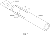
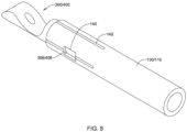
- FIGS. 7-9 illustrate attachment of the example first and/or second part 300 and/or the example first and/or second part 400 to the elongate shaft 110 and/or the medical implant 130.
- the elongate shaft 110 and/or the medical implant 130 may include at least one window 140 extending through a wall of the elongate shaft 110 and/or the medical implant 130 configured to receive the at least one protrusion 306/406.
- the elongate shaft 110 and/or the medical implant 130 may include at least one longitudinally-oriented and/or radially-oriented cut 142 extending away from an end of the elongate shaft 110 and/or the medical implant 130 (e.g., extending proximally from a distal end of the elongate shaft 110, extending distally from a proximal end of the medical implant 130).
- the at least one longitudinally-oriented and/or radially-oriented cut 142 may permit flexure of the elongate shaft 110 and/or the medical implant 130 over the at least one protrusion 306/406, thereby facilitating assembly of the first and/or second part 300/400 and the elongate shaft 110 and/or the medical implant 130.
- Material on opposing sides of the at least one longitudinally-oriented and/or radially-oriented cut 142 may be fixedly secured together after the tubular (proximal or distal) portion 302/402 is inserted into the proximal end of the medical implant 130 and/or the distal end of the elongate shaft 110.
- heat may be applied to the elongate shaft 110 and/or the medical implant 130, such as with a laser, a welder, or other suitable means.
- applying heat to the elongate shaft 110 and/or the medical implant 130 may include welding (e.g., seam welding, spot welding, etc.) the elongate shaft 110 and/or the medical implant 130 to itself along each of the at least one longitudinally-oriented and/or radially-oriented cut 142, shown at least partially filled-in (e.g., welded) in FIG.
- pressure, compression, and/or other means may be used to fixedly secure material on opposing sides of the at least one longitudinally-oriented and/or radially-oriented cut 142 after the tubular (proximal or distal) portion 302/402 is inserted into the proximal end of the medical implant 130 and/or the distal end of the elongate shaft 110, thereby creating a mechanical engagement, interference fit, and/or lock fixedly and non-reversibly (e.g., permanently) attaching the first and/or second part 200 to the elongate shaft 110 and/or the medical implant 130.
- pressure, compression, and/or other means e.g., swaging, adhesives, chemical dissolution and re-hardening, etc.
- the elongate shaft 110 and/or the medical implant 130 may include a helical and/or radial-oriented cut 144 extending away from an end of the elongate shaft 110 and/or the medical implant 130 (e.g., extending proximally from a distal end of the elongate shaft 110, extending distally from a proximal end of the medical implant 130).
- the helical and/or radially-oriented cut 144 may permit flexure of the elongate shaft 110 and/or the medical implant 130 over the at least one protrusion 306/406, thereby facilitating assembly of the first and/or second part 300/400 and the elongate shaft 110 and/or the medical implant 130.
- Material on opposing sides of the helical and/or radially-oriented cut 142 may be fixedly secured together after the tubular (proximal or distal) portion 302/402 is inserted into the proximal end of the medical implant 130 and/or the distal end of the elongate shaft 110, using any of the methods and/or means discussed above with respect to at least one longitudinally-oriented and/or radially-oriented cut 142.
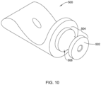
- FIG. 10 illustrates an example first and/or second part 500 that corresponds to and/or may be used in place of the first part 172 and/or the second part 174.
- the first and/or second part 500 of FIG. 10 may include a tubular portion 502 corresponding to the tubular proximal portion 182 of the first part 172 and/or the tubular distal portion 184 of the second part 174.
- the tubular (proximal or distal) portion 502 of the first and/or second part 500 may include an engagement feature 504 configured to non-releasably engage the first and/or second part 500 with the elongate shaft 110 and/or the medical implant 130.
- the engagement feature 504 of the first and/or second part 500 may correspond to the engagement feature of the first part 172 and/or the engagement feature of the second part 174.
- the engagement feature 504 may include one or more recesses 506 extending into an outer surface of the tubular (proximal or distal) portion 502 of the first and/or second part 500.
- the one or more recesses 506 may include and/or define an hourglass shape extending radially inward from the outer surface of the tubular (proximal or distal) portion 502 of the first and/or second part 500.
- At least one plug 150 may each be inserted through at least one window 140 in the elongate shaft 110 and/or the medical implant 130.
- the at least one plug 150 may be fixedly attached to the elongate shaft 110 and/or the medical implant 130 after the at least one plug 150 is inserted through the at least one window 140.
- a laser or other suitable heat source may be used to apply heat to the at least one plug 150 and/or the elongate shaft 110 and/or the medical implant 130 to fixedly attach the first and/or second part 500 to the elongate shaft 110 and/or the medical implant 130.
- Heating the at least one plug 150 and/or the elongate shaft 110 and/or the medical implant 130 may cause melting and/or reflow of the at least one plug 150 and/or the elongate shaft 110 and/or the medical implant 130, wherein a portion of the at least one plug 150 and/or the elongate shaft 110 and/or the medical implant 130 extends into the engagement feature 504 and/or the one or more recesses 506 extending into the outer surface of the tubular (proximal or distal) portion 502 of the first and/or second part 500, thereby creating a mechanical engagement, interference fit, and/or lock fixedly and non-reversibly (e.g., permanently) attaching the first and/or second part 500 to the elongate shaft 110 and/or the medical implant 130, as shown in FIG.
- melting and/or reflow of the at least one plug 150 and/or the elongate shaft 110 and/or the medical implant 130 may cause the at least one plug 150 to become an integral part of the elongate shaft 110 and/or the medical implant 130, wherein after heating, melting, and/or reflow, a portion of the elongate shaft 110 and/or the medical implant 130 extends into the one or more recesses 506 extending into the outer surface of the tubular (proximal or distal) portion 502 of the first and/or second part 500.
- pressure, compression, and/or other means may be used to fixedly and non-reversibly (e.g., permanently) attach the first and/or second part 500 to the elongate shaft 110 and/or the medical implant 130.
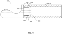
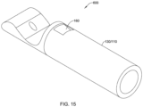
- FIG. 13 illustrates an example first and/or second part 600 that corresponds to and/or may be used in place of the first part 172 and/or the second part 174.
- the first and/or second part 600 of FIG. 13 may include a tubular portion 602 corresponding to the tubular proximal portion 182 of the first part 172 and/or the tubular distal portion 184 of the second part 174.
- the tubular (proximal or distal) portion 602 of the first and/or second part 600 may include an engagement feature 604 configured to non-releasably engage the first and/or second part 600 with the elongate shaft 110 and/or the medical implant 130.
- the engagement feature 604 of the first and/or second part 600 may correspond to the engagement feature of the first part 172 and/or the engagement feature of the second part 174.
- the engagement feature 604 may include one or more recesses 606 extending into an outer surface of the tubular (proximal or distal) portion 602 of the first and/or second part 600.
- the engagement feature 604 may include at least one protrusion 608 extending radially outward from the tubular (proximal or distal) portion 602 of the first and/or second part 600.
- the engagement feature 604 may include both the one or more recesses 606 extending into the outer surface of the tubular (proximal or distal) portion 602 of the first and/or second part 600 and the at least one protrusion 608 extending radially outward from the tubular (proximal or distal) portion 602 of the first and/or second part 600.
- first and/or second part 600 for example metallic materials, polymer materials, composite materials, etc., are described below.
- a portion of the elongate shaft 110 and/or the medical implant 130 may extend into the one or more recesses 606 extending into the outer surface of the tubular (proximal or distal) portion 602 of the first and/or second part 600 and/or the portion of the elongate shaft 110 and/or the medical implant 130 may engage against the at least one protrusion 608 extending radially outward from the tubular (proximal or distal) portion 602 of the first and/or second part 600, after the tubular (proximal or distal) portion 602 of the first and/or second part 600 is inserted into the distal end 116 of the elongate shaft 110 and/or the proximal end of the medical implant 130, thereby preventing withdrawal of the tubular (proximal or distal) portion 602 of the first and/or second part 600 from the distal end 116 of the elongate shaft 110 and/or the proximal end of the medical implant 130.
- the portion of the elongate shaft 110 and/or the medical implant 130 extending into the one or more recesses 606 extending into the outer surface of the tubular (proximal or distal) portion 602 of the first and/or second part 600 may include a moveable tab 160 biased radially inward.
- the moveable tab 160 may be self-biased radially inward.
- the moveable tab 160 may include a plurality of moveable tabs (e.g., two moveable tabs, three moveable tabs, four moveable tabs, etc.).
- the tubular (proximal or distal) portion 602 of the first and/or second part 600 when the tubular (proximal or distal) portion 602 of the first and/or second part 600 is inserted into the distal end 116 of the elongate shaft 110 and/or the proximal end of the medical implant 130, the tubular (proximal or distal) portion 602 of the first and/or second part 600 and/or the at least one protrusion 608 extending radially outward from the tubular (proximal or distal) portion 602 of the first and/or second part 600 may deflect the moveable tab 160 radially outward until the moveable tab 160 reaches the one or more recesses 606 extending into the outer surface of the tubular (proximal or distal) portion 602 of the first and/or second part 600, at which time, the moveable tab 160 will be biased radially inward into the one or more recesses 606 extending into the outer surface of the tubular (proximal or distal) portion 60
- a method of making the medical implant system 100 may comprise: inserting the first part 172 (e.g., the first and/or second part 200, 300, 400, 500, 600) of the attachment mechanism 170 into the distal end 116 of the elongate shaft 110 and securing the first part 172 (e.g., the first and/or second part 200, 300, 400, 500, 600) of the attachment mechanism 170 to the elongate shaft 110; inserting the second part 174 (e.g., the first and/or second part 200, 300, 400, 500, 600) of the attachment mechanism 170 into the proximal end of the medical implant 130, wherein the second part 174 (e.g., the first and/or second part 200, 300, 400, 500, 600) of the attachment mechanism 170 is formed from a first metallic material and the medical implant 130 is formed from a second metallic material dissimilar from the first metallic material; and applying heat to the elongate shaft 110 and/or the medical implant 130 to fixedly attach
- the elongate shaft 110 and/or the medical implant 130 may be formed from a shape memory alloy such as, but not limited to, a nickel-titanium alloy.
- the method may include applying pressure, compression, and/or other means (e.g., swaging, adhesives, chemical dissolution and re-hardening, etc.) to the elongate shaft 110 and/or the medical implant 130 to fixedly attach the first part 172 (e.g., the first and/or second part 200, 300, 400, 500, 600) of the attachment mechanism 170 to the elongate shaft 110 and/or the second part 174 (e.g., the first and/or second part 200, 300, 400, 500, 600) of the attachment mechanism 170 to the medical implant 130.
- first part 172 e.g., the first and/or second part 200, 300, 400, 500, 600
- the second part 174 e.g., the first and/or second part 200, 300, 400, 500, 600
- applying heat to the elongate shaft 110 and/or the medical implant 130 may cause a portion of the elongate shaft 110 and/or the medical implant 130 to reflow into one or more recesses extending into the outer surface of the first part 172 (e.g., the first and/or second part 200, 300, 400, 500, 600) of the attachment mechanism 170 and/or the second part 174 (e.g., the first and/or second part 200, 300, 400, 500, 600) of the attachment mechanism 170.
- the first part 172 e.g., the first and/or second part 200, 300, 400, 500, 600
- the second part 174 e.g., the first and/or second part 200, 300, 400, 500, 600
- applying heat to the elongate shaft 110 and/or the medical implant 130 includes welding (e.g., seam welding, spot welding, etc.) the elongate shaft 110 and/or the medical implant 130 to itself, and/or reflowing the elongate shaft 110 and/or the medical implant 130.
- applying heat to the elongate shaft 110 and/or the medical implant 130 includes heating a plug 150 inserted through a window 140 in the elongate shaft 110 and/or the medical implant 130 such that the plug 150 reflows with the elongate shaft 110 and/or the medical implant 130 and becomes integrated with the elongate shaft 110 and/or the medical implant 130.
- pressure, compression, and/or other means may be used to fixedly attach the second part 174 (e.g., the first and/or second part 200, 300, 400, 500, 600) of the attachment mechanism 170 to the medical implant 130, and/or the first part 172 (e.g., the first and/or second part 200, 300, 400, 500, 600) of the attachment mechanism 170 to the elongate shaft 110.
- the second part 174 e.g., the first and/or second part 200, 300, 400, 500, 600
- first part 172 e.g., the first and/or second part 200, 300, 400, 500, 600
- the method may further comprise applying heat, pressure, compression, and/or other means (e.g., swaging, adhesives, chemical dissolution and re-hardening, etc.) to the distal end 116 of the elongate shaft 110 to fixedly attach the first part 172 (e.g., the first and/or second part 200, 300, 400, 500, 600) of the attachment mechanism 170 to the distal end 116 of the elongate shaft 110.
- the first part 172 e.g., the first and/or second part 200, 300, 400, 500, 600
- the attachment mechanism 170 is formed from the first metallic material and the elongate shaft 110 is formed from a third metallic material dissimilar from the first metallic material.
- the third metallic material is a shape memory alloy such as, but not limited to, a nickel-titanium alloy.
- a method of delivering the medical implant 130 to a treatment site may include inserting the microcatheter into a patient's anatomy and guiding the distal end of the microcatheter to a location adjacent the treatment site.
- the method may include inserting the medical implant 130 disposed at and/or proximate the distal end 116 of the elongate shaft 110 into a proximal end of the lumen disposed within the microcatheter.
- the medical implant 130 may be inserted into the lumen of the microcatheter after the microcatheter is inserted into the patient's anatomy.
- the method may include advancing the medical implant 130 through the microcatheter to the treatment site.
- the medical implant 130 may be releasably attached to the distal end 116 of the elongate shaft 110 by the release wire 120 extending through the lumen 112 within the elongate shaft 110.
- the securement member may extend proximally from the elongate shaft 110, and the securement member may be fixedly attached to the elongate shaft 110 and the release wire 120.
- the medical implant 130 may be inserted into the proximal end of the lumen of the microcatheter and advanced through the microcatheter to a distal end of the microcatheter before the microcatheter is inserted into the patient's anatomy.
- the proximal portion of the securement member may be fixedly attached to a proximal end of the release wire 120 and the distal portion of the securement member may be fixedly attached to the proximal end of the elongate shaft 110.
- the first part 172 of the attachment mechanism 170 may be attached to the distal end 116 of the elongate shaft 110, and the second part 174 of the attachment mechanism 170 may be fixedly attached to a proximal end of the medical implant 130.
- the release wire 120 may be slidably disposed within a lumen of the distal portion of the securement member, the lumen 112 of the elongate shaft 110, the first longitudinal lumen of the first part 172 of the attachment mechanism 170, and the second longitudinal lumen of the second part 174 of the attachment mechanism 170.
- the method may include translating the proximal portion of the securement member proximally away from the proximal end of the elongate shaft 110 while the elongate shaft 110 is maintained in a fixed position with respect to the treatment site to translate the release wire 120 relative to the elongate shaft 110 and/or the attachment mechanism 170 to shift the release wire 120 from an interlocked position to a released position, thereby releasing the medical implant 130 from the elongate shaft 110.
- the method may also include proximal withdrawal of the elongate shaft 110 and/or the microcatheter from the treatment site.
- the elongate shaft 110 may be withdrawn proximally through the lumen of the microcatheter and removed, and the microcatheter may then be withdrawn and/or removed from the patient's anatomy.
- the elongate shaft 110 may be withdrawn proximally far enough for the distal end 116 of the elongate shaft 110 and/or the first part 172 of the attachment mechanism 170 to be positioned within the distal end and/or the lumen of the microcatheter. The elongate shaft 110 and the microcatheter may then be withdrawn together from the patient's anatomy.
- the elongate shaft 110 may be removed through the lumen of the microcatheter, and the microcatheter may be left and/or held in place within the patient's anatomy. If needed, a second elongate shaft and associated second medical device may then be inserted into the proximal end of the lumen of the microcatheter and advanced to the treatment site for deployment. Additional repetitions of the device(s) described herein, as well as the described method steps, may be used as needed or desired for a particular procedure.
- the materials that can be used for the various components of the medical implant system 100, the elongate shaft 110, the release wire 120, the medical implant 130, the at least one plug 150, the attachment mechanism 170, the microcatheter, the first and/or second part 200/300/400/500/600, etc. (and/or other systems disclosed herein) and the various elements thereof disclosed herein may include those commonly associated with medical devices.
- the following discussion makes reference to the medical implant system 100, the elongate shaft 110, the release wire 120, the medical implant 130, the at least one plug 150, the attachment mechanism 170, the microcatheter, the first and/or second part 200/300/400/500/600, etc.
- the medical implant system 100, the elongate shaft 110, the release wire 120, the medical implant 130, the at least one plug 150, the attachment mechanism 170, the microcatheter, the first and/or second part 200/300/400/500/600, etc., and/or components thereof such as, but not limited to, the first part 172, the second part 174, the tubular proximal portion 182, the tubular distal portion 184, the tubular (proximal or distal) portion 202/302/402/502/602, the engagement feature 204/304/404/504/604, the at least one protrusion 306/406/608, etc.
- suitable metals and metal alloys include stainless steel, such as but not limited to 444V, 444L, and 314LV stainless steel; mild steel; nickel-titanium alloy such as linear-elastic and/or super-elastic nitinol; other nickel alloys such as nickel-chromium-molybdenum alloys (e.g., UNS: N06625 such as INCONEL ® 625, UNS: N06022 such as HASTELLOY ® C-22 ® , UNS: N10276 such as HASTELLOY ® C276 ® , other HASTELLOY ® alloys, and the like), nickel-copper alloys (e.g., UNS: N04400 such as MONEL ® 400, NlCKELVAC ® 400, NICORROS ® 400, and the like), nickel-cobalt-chromium-molybdenum alloys (e.g., UNS: R44035 such as MP35-N ®
- Linear elastic and/or non-super-elastic nitinol may be distinguished from super elastic nitinol in that the linear elastic and/or non-super-elastic nitinol does not display a substantial "superelastic plateau” or “flag region” in its stress/strain curve like super elastic nitinol does.
- linear elastic and/or non-super-elastic nitinol as recoverable strain increases, the stress continues to increase in a substantially linear, or a somewhat, but not necessarily entirely linear relationship until plastic deformation begins or at least in a relationship that is more linear than the super elastic plateau and/or flag region that may be seen with super elastic nitinol.
- linear elastic and/or non-super-elastic nitinol may also be termed "substantially" linear elastic and/or non-super-elastic nitinol.
- linear elastic and/or non-super-elastic nitinol may also be distinguishable from super elastic nitinol in that linear elastic and/or non-super-elastic nitinol may accept up to about 2-5% strain while remaining substantially elastic (e.g., before plastically deforming) whereas super elastic nitinol may accept up to about 8% strain before plastically deforming. Both of these materials can be distinguished from other linear elastic materials such as stainless steel (that can also be distinguished based on its composition), which may accept only about 0.2 to 0.44 percent strain before plastically deforming.
- the linear elastic and/or non-super-elastic nickel-titanium alloy is an alloy that does not show any martensite/austenite phase changes that are detectable by differential scanning calorimetry (DSC) and dynamic metal thermal analysis (DMTA) analysis over a large temperature range.
- DSC differential scanning calorimetry
- DMTA dynamic metal thermal analysis
- the mechanical bending properties of such material may therefore be generally inert to the effect of temperature over this very broad range of temperature.
- the mechanical bending properties of the linear elastic and/or non-super-elastic nickel-titanium alloy at ambient or room temperature are substantially the same as the mechanical properties at body temperature, for example, in that they do not display a super-elastic plateau and/or flag region.
- the linear elastic and/or non-super-elastic nickel-titanium alloy maintains its linear elastic and/or non-super-elastic characteristics and/or properties.
- the linear elastic and/or non-super-elastic nickel-titanium alloy may be in the range of about 50 to about 60 weight percent nickel, with the remainder being essentially titanium. In some embodiments, the composition is in the range of about 54 to about 57 weight percent nickel.
- a suitable nickel-titanium alloy is FHP-NT alloy commercially available from Furukawa Techno Material Co. of Kanagawa, Japan. Other suitable materials may include ULTANIUM TM (available from Neo-Metrics) and GUM METAL TM (available from Toyota).
- a superelastic alloy for example a superelastic nitinol can be used to achieve desired properties.
- portions or all of the medical implant system 100, the elongate shaft 110, the release wire 120, the medical implant 130, the at least one plug 150, the attachment mechanism 170, the microcatheter, the first and/or second part 200/300/400/500/600, etc., and/or components thereof, may also be doped with, made of, or otherwise include a radiopaque material.
- Radiopaque materials are understood to be materials capable of producing a relatively bright image on a fluoroscopy screen or another imaging technique during a medical procedure.
- radiopaque materials can include, but are not limited to, gold, platinum, palladium, tantalum, tungsten alloy, polymer material loaded with a radiopaque filler, and the like.
- radiopaque marker bands and/or coils may also be incorporated into the design of the medical implant system 100, the elongate shaft 110, the release wire 120, the medical implant 130, the at least one plug 150, the attachment mechanism 170, the microcatheter, the first and/or second part 200/300/400/500/600, etc. to achieve the same result.
- a degree of Magnetic Resonance Imaging (MRI) compatibility is imparted into the medical implant system 100, the elongate shaft 110, the release wire 120, the medical implant 130, the at least one plug 150, the attachment mechanism 170, the microcatheter, the first and/or second part 200/300/400/500/600, etc.
- MRI Magnetic Resonance Imaging
- the medical implant system 100, the elongate shaft 110, the release wire 120, the medical implant 130, the at least one plug 150, the attachment mechanism 170, the microcatheter, the first and/or second part 200/300/400/500/600, etc., and/or components or portions thereof may be made of a material that does not substantially distort the image and create substantial artifacts (e.g., gaps in the image). Certain ferromagnetic materials, for example, may not be suitable because they may create artifacts in an MRI image.
- the medical implant system 100, the elongate shaft 110, the release wire 120, the medical implant 130, the at least one plug 150, the attachment mechanism 170, the microcatheter, the first and/or second part 200/300/400/500/600, etc., or portions thereof, may also be made from a material that the MRI machine can image.
- Some materials that exhibit these characteristics include, for example, tungsten, cobalt-chromium-molybdenum alloys (e.g., UNS: R44003 such as ELGILOY ® , PHYNOX ® , and the like), nickel-cobalt-chromium-molybdenum alloys (e.g., UNS: R44035 such as MP35-N ® and the like), nitinol, and the like, and others.
- cobalt-chromium-molybdenum alloys e.g., UNS: R44003 such as ELGILOY ® , PHYNOX ® , and the like
- nickel-cobalt-chromium-molybdenum alloys e.g., UNS: R44035 such as MP35-N ® and the like
- nitinol and the like, and others.
- the medical implant system 100, the elongate shaft 110, the release wire 120, the medical implant 130, the at least one plug 150, the attachment mechanism 170, the microcatheter, the first and/or second part 200/300/400/500/600, etc., and/or portions thereof may be made from or include a polymer or other suitable material.
- suitable polymers may include polytetrafluoroethylene (PTFE), ethylene tetrafluoroethylene (ETFE), fluorinated ethylene propylene (FEP), polyoxymethylene (POM, for example, DELRIN ® available from DuPont), polyether block ester, polyurethane (for example, Polyurethane 85A), polypropylene (PP), polyvinylchloride (PVC), polyether-ester (for example, ARNITEL ® available from DSM Engineering Plastics), ether or ester based copolymers (for example, butylene/poly(alkylene ether) phthalate and/or other polyester elastomers such as HYTREL ® available from DuPont), polyamide (for example, DURETHAN ® available from Bayer or CRISTAMID ® available from Elf Atochem), elastomeric polyamides, block polyamide/ethers, polyether block amide (PEBA, for example available under the trade name PEBAX ®
- the medical implant system 100, the elongate shaft 110, the release wire 120, the medical implant 130, the at least one plug 150, the attachment mechanism 170, the microcatheter, the first and/or second part 200/300/400/500/600, etc. disclosed herein may include a fabric material disposed over or within the structure.
- the fabric material may be composed of a biocompatible material, such a polymeric material or biomaterial, adapted to promote tissue ingrowth.
- the fabric material may include a bioabsorbable material.
- suitable fabric materials include, but are not limited to, polyethylene glycol (PEG), nylon, polytetrafluoroethylene (PTFE, ePTFE), a polyolefinic material such as a polyethylene, a polypropylene, polyester, polyurethane, and/or blends or combinations thereof.
- PEG polyethylene glycol
- PTFE polytetrafluoroethylene
- ePTFE polytetrafluoroethylene
- a polyolefinic material such as a polyethylene, a polypropylene, polyester, polyurethane, and/or blends or combinations thereof.
- the medical implant system 100, the elongate shaft 110, the release wire 120, the medical implant 130, the at least one plug 150, the attachment mechanism 170, the microcatheter, the first and/or second part 200/300/400/500/600, etc. may include and/or be formed from a textile material.
- suitable textile materials may include synthetic yarns that may be flat, shaped, twisted, textured, pre-shrunk or un-shrunk.
- Synthetic biocompatible yarns suitable for use in the present invention include, but are not limited to, polyesters, including polyethylene terephthalate (PET) polyesters, polypropylenes, polyethylenes, polyurethanes, polyolefins, polyvinyls, polymethylacetates, polyamides, naphthalene dicarboxylene derivatives, natural silk, and polytetrafluoroethylenes.
- PET polyethylene terephthalate
- polypropylenes polyethylenes
- polyethylenes polyurethanes
- polyolefins polyvinyls
- polymethylacetates polyamides
- naphthalene dicarboxylene derivatives polymethylacetates
- polyamides naphthalene dicarboxylene derivatives
- natural silk and polytetrafluoroethylenes.
- at least one of the synthetic yarns may be a metallic yarn or a glass or ceramic yarn or fiber.
- Useful metallic yarns include those yarns made from or containing
- the yarns are made from thermoplastic materials including, but not limited to, polyesters, polypropylenes, polyethylenes, polyurethanes, polynaphthalenes, polytetrafluoroethylenes, and the like.
- the yarns may be of the multifilament, monofilament, or spun-types.
- the type and denier of the yarn chosen may be selected in a manner which forms a biocompatible and implantable prosthesis and, more particularly, a vascular structure having desirable properties.
- the medical implant system 100, the elongate shaft 110, the release wire 120, the medical implant 130, the at least one plug 150, the attachment mechanism 170, the microcatheter, the first and/or second part 200/300/400/500/600, etc. may include and/or be treated with a suitable therapeutic agent.
- suitable therapeutic agents may include anti-thrombogenic agents (such as heparin, heparin derivatives, urokinase, and PPack (dextrophenylalanine proline arginine chloromethylketone)); anti-proliferative agents (such as enoxaparin, angiopeptin, monoclonal antibodies capable of blocking smooth muscle cell proliferation, hirudin, and acetylsalicylic acid); anti-inflammatory agents (such as dexamethasone, prednisolone, corticosterone, budesonide, estrogen, sulfasalazine, and mesalamine); antineoplastic/antiproliferative/anti-mitotic agents (such as paclitaxel, 5-fluorouracil, cisplatin, vinblastine, vincristine, epothilones, endostatin, angiostatin and thymidine kinase inhibitors); anesthetic agents (such as lido
Landscapes
- Health & Medical Sciences (AREA)
- Engineering & Computer Science (AREA)
- Biomedical Technology (AREA)
- Life Sciences & Earth Sciences (AREA)
- General Health & Medical Sciences (AREA)
- Veterinary Medicine (AREA)
- Public Health (AREA)
- Heart & Thoracic Surgery (AREA)
- Vascular Medicine (AREA)
- Animal Behavior & Ethology (AREA)
- Surgery (AREA)
- Transplantation (AREA)
- Oral & Maxillofacial Surgery (AREA)
- Cardiology (AREA)
- Reproductive Health (AREA)
- Nuclear Medicine, Radiotherapy & Molecular Imaging (AREA)
- Medical Informatics (AREA)
- Molecular Biology (AREA)
- Prostheses (AREA)
- Surgical Instruments (AREA)
- Media Introduction/Drainage Providing Device (AREA)
Claims (6)
- Medizinisches Implantatsystem (100), das ein Implantat (130) und einen Befestigungsmechanismus aufweist, wobei der Befestigungsmechanismus (170) aufweist:einen ersten Teil (172; 300; 400; 600), der konfiguriert ist, fest an einem distalen Ende (116) eines länglichen Schafts (110) angebracht zu werden; undeinen zweiten Teil (174; 300; 400; 600), der fest an einem proximalen Ende eines medizinischen Implantats (130) angebracht ist;wobei ein röhrenförmiger distaler Abschnitt (184; 302; 402; 602) des zweiten Teils (174; 300; 400; 600) ein Eingriffsmerkmal (304; 404; 604) aufweist, das konfiguriert ist, den zweiten Teil (174; 300; 400; 600) nicht lösbar mit dem medizinischen Implantat (130) in Eingriff zu bringen;dadurch gekennzeichnet, dass das Eingriffsmerkmal (604) eine oder mehrere Aussparungen (606) aufweist, die sich in eine Außenfläche des röhrenförmigen distalen Abschnitts (602) des zweiten Teils (600) erstrecken, wobei sich ein Abschnitt des medizinischen Implantats (130) in die eine oder mehreren Aussparungen (606) erstreckt, und wobei der Abschnitt (602) des medizinischen Implantats (130), der sich in die eine oder mehreren Aussparungen (606) erstreckt, eine bewegliche Lasche (160) aufweist, die radial nach innen vorgespannt ist;
oderdass das Eingriffsmerkmal (304; 404) mindestens einen Vorsprung (306; 406) aufweist, der sich von einer Außenfläche des röhrenförmigen distalen Abschnitts (302; 402) des zweiten Teils (300; 400) radial nach außen erstreckt, und wobei das medizinische Implantat (130) mindestens ein Fenster (140) aufweist, das sich durch eine Wand des medizinischen Implantats (130) erstreckt und konfiguriert ist, den mindestens einen Vorsprung (306; 406) aufzunehmen. - System nach Anspruch 1, wobei der zweite Teil aus einem ersten metallischen Material (174; 300; 400; 600) ausgebildet ist und das medizinische Implantat (130) aus einem zweiten metallischen Material ausgebildet ist, das sich vom ersten metallischen Material unterscheidet.
- System nach Anspruch 2, wobei das zweite metallische Material eine Formgedächtnislegierung ist.
- System nach einem der Ansprüche 1 bis 3, des Weiteren aufweisend: wobei ein röhrenförmiger proximaler Abschnitt (182; 302; 402; 602) des ersten Teils (172; 300; 400; 600) ein Eingriffsmerkmal (304; 404; 604) aufweist, das konfiguriert ist, den ersten Teil (172; 300; 400; 600) nicht lösbar mit dem länglichen Schaft (110) in Eingriff zu bringen.
- System nach Anspruch 4, wobei der erste Teil (172; 300; 400; 600) und der zweite Teil (174; 300; 400; 600) konfiguriert sind, sich miteinander zu verriegeln, so dass eine relative axiale Verschiebung zwischen dem ersten Teil (172; 300; 400; 600) und dem zweiten Teil (174; 300; 400; 600) verhindert wird, wenn der erste Teil (172; 300; 400; 600) an dem zweiten Teil (174; 300; 400; 600) anliegt und ein erstes Längslumen des ersten Teils (172; 300; 400; 600) koaxial mit einem zweiten Längslumen des zweiten Teils (174; 300; 400; 600) ausgerichtet ist.
- System nach Anspruch 5, wobei der erste Teil (172; 300; 400; 600) und der zweite Teil (174; 300; 400; 600) konfiguriert sind, sich miteinander zu verriegeln, so dass eine relative seitliche Verschiebung zwischen dem ersten Teil (172; 300; 400; 600) und dem zweiten Teil (174; 300; 400; 600) verhindert wird, wenn der erste Teil (172; 300; 400; 600) an dem zweiten Teil (174; 300; 460; 600) anliegt, das erste Längslumen koaxial mit dem zweiten Längslumen ausgerichtet ist und ein Freigabedraht (120) verschiebbar mit dem ersten Längslumen und dem zweiten Längslumen in Eingriff steht.
Applications Claiming Priority (2)
| Application Number | Priority Date | Filing Date | Title |
|---|---|---|---|
| US201862634498P | 2018-02-23 | 2018-02-23 | |
| PCT/US2019/018724 WO2019164909A1 (en) | 2018-02-23 | 2019-02-20 | Medical implant attachment mechanism |
Publications (2)
| Publication Number | Publication Date |
|---|---|
| EP3755239A1 EP3755239A1 (de) | 2020-12-30 |
| EP3755239B1 true EP3755239B1 (de) | 2024-12-18 |
Family
ID=65818595
Family Applications (1)
| Application Number | Title | Priority Date | Filing Date |
|---|---|---|---|
| EP19712326.8A Active EP3755239B1 (de) | 2018-02-23 | 2019-02-20 | Befestigungsmechanismus für medizinische implantate |
Country Status (5)
| Country | Link |
|---|---|
| US (2) | US20190262153A1 (de) |
| EP (1) | EP3755239B1 (de) |
| JP (1) | JP2021514272A (de) |
| CN (1) | CN111741721B (de) |
| WO (1) | WO2019164909A1 (de) |
Families Citing this family (148)
| Publication number | Priority date | Publication date | Assignee | Title |
|---|---|---|---|---|
| US9060770B2 (en) | 2003-05-20 | 2015-06-23 | Ethicon Endo-Surgery, Inc. | Robotically-driven surgical instrument with E-beam driver |
| US20070084897A1 (en) | 2003-05-20 | 2007-04-19 | Shelton Frederick E Iv | Articulating surgical stapling instrument incorporating a two-piece e-beam firing mechanism |
| US11896225B2 (en) | 2004-07-28 | 2024-02-13 | Cilag Gmbh International | Staple cartridge comprising a pan |
| US9072535B2 (en) | 2011-05-27 | 2015-07-07 | Ethicon Endo-Surgery, Inc. | Surgical stapling instruments with rotatable staple deployment arrangements |
| US11998198B2 (en) | 2004-07-28 | 2024-06-04 | Cilag Gmbh International | Surgical stapling instrument incorporating a two-piece E-beam firing mechanism |
| US10159482B2 (en) | 2005-08-31 | 2018-12-25 | Ethicon Llc | Fastener cartridge assembly comprising a fixed anvil and different staple heights |
| US11246590B2 (en) | 2005-08-31 | 2022-02-15 | Cilag Gmbh International | Staple cartridge including staple drivers having different unfired heights |
| US7669746B2 (en) | 2005-08-31 | 2010-03-02 | Ethicon Endo-Surgery, Inc. | Staple cartridges for forming staples having differing formed staple heights |
| US11793518B2 (en) | 2006-01-31 | 2023-10-24 | Cilag Gmbh International | Powered surgical instruments with firing system lockout arrangements |
| US20120292367A1 (en) | 2006-01-31 | 2012-11-22 | Ethicon Endo-Surgery, Inc. | Robotically-controlled end effector |
| US8186555B2 (en) | 2006-01-31 | 2012-05-29 | Ethicon Endo-Surgery, Inc. | Motor-driven surgical cutting and fastening instrument with mechanical closure system |
| US8708213B2 (en) | 2006-01-31 | 2014-04-29 | Ethicon Endo-Surgery, Inc. | Surgical instrument having a feedback system |
| US7845537B2 (en) | 2006-01-31 | 2010-12-07 | Ethicon Endo-Surgery, Inc. | Surgical instrument having recording capabilities |
| US8992422B2 (en) | 2006-03-23 | 2015-03-31 | Ethicon Endo-Surgery, Inc. | Robotically-controlled endoscopic accessory channel |
| US11980366B2 (en) | 2006-10-03 | 2024-05-14 | Cilag Gmbh International | Surgical instrument |
| US8684253B2 (en) | 2007-01-10 | 2014-04-01 | Ethicon Endo-Surgery, Inc. | Surgical instrument with wireless communication between a control unit of a robotic system and remote sensor |
| US8632535B2 (en) | 2007-01-10 | 2014-01-21 | Ethicon Endo-Surgery, Inc. | Interlock and surgical instrument including same |
| US8701958B2 (en) | 2007-01-11 | 2014-04-22 | Ethicon Endo-Surgery, Inc. | Curved end effector for a surgical stapling device |
| US8931682B2 (en) | 2007-06-04 | 2015-01-13 | Ethicon Endo-Surgery, Inc. | Robotically-controlled shaft based rotary drive systems for surgical instruments |
| US11857181B2 (en) | 2007-06-04 | 2024-01-02 | Cilag Gmbh International | Robotically-controlled shaft based rotary drive systems for surgical instruments |
| US11849941B2 (en) | 2007-06-29 | 2023-12-26 | Cilag Gmbh International | Staple cartridge having staple cavities extending at a transverse angle relative to a longitudinal cartridge axis |
| US11986183B2 (en) | 2008-02-14 | 2024-05-21 | Cilag Gmbh International | Surgical cutting and fastening instrument comprising a plurality of sensors to measure an electrical parameter |
| US8636736B2 (en) | 2008-02-14 | 2014-01-28 | Ethicon Endo-Surgery, Inc. | Motorized surgical cutting and fastening instrument |
| JP5410110B2 (ja) | 2008-02-14 | 2014-02-05 | エシコン・エンド−サージェリィ・インコーポレイテッド | Rf電極を有する外科用切断・固定器具 |
| US8573465B2 (en) | 2008-02-14 | 2013-11-05 | Ethicon Endo-Surgery, Inc. | Robotically-controlled surgical end effector system with rotary actuated closure systems |
| US9615826B2 (en) | 2010-09-30 | 2017-04-11 | Ethicon Endo-Surgery, Llc | Multiple thickness implantable layers for surgical stapling devices |
| US8210411B2 (en) | 2008-09-23 | 2012-07-03 | Ethicon Endo-Surgery, Inc. | Motor-driven surgical cutting instrument |
| US9005230B2 (en) | 2008-09-23 | 2015-04-14 | Ethicon Endo-Surgery, Inc. | Motorized surgical instrument |
| US9386983B2 (en) | 2008-09-23 | 2016-07-12 | Ethicon Endo-Surgery, Llc | Robotically-controlled motorized surgical instrument |
| US8608045B2 (en) | 2008-10-10 | 2013-12-17 | Ethicon Endo-Sugery, Inc. | Powered surgical cutting and stapling apparatus with manually retractable firing system |
| US9592050B2 (en) | 2010-09-30 | 2017-03-14 | Ethicon Endo-Surgery, Llc | End effector comprising a distal tissue abutment member |
| US10945731B2 (en) | 2010-09-30 | 2021-03-16 | Ethicon Llc | Tissue thickness compensator comprising controlled release and expansion |
| US12213666B2 (en) | 2010-09-30 | 2025-02-04 | Cilag Gmbh International | Tissue thickness compensator comprising layers |
| US9320523B2 (en) | 2012-03-28 | 2016-04-26 | Ethicon Endo-Surgery, Llc | Tissue thickness compensator comprising tissue ingrowth features |
| US9629814B2 (en) | 2010-09-30 | 2017-04-25 | Ethicon Endo-Surgery, Llc | Tissue thickness compensator configured to redistribute compressive forces |
| US11925354B2 (en) | 2010-09-30 | 2024-03-12 | Cilag Gmbh International | Staple cartridge comprising staples positioned within a compressible portion thereof |
| US11812965B2 (en) | 2010-09-30 | 2023-11-14 | Cilag Gmbh International | Layer of material for a surgical end effector |
| US8695866B2 (en) | 2010-10-01 | 2014-04-15 | Ethicon Endo-Surgery, Inc. | Surgical instrument having a power control circuit |
| AU2012250197B2 (en) | 2011-04-29 | 2017-08-10 | Ethicon Endo-Surgery, Inc. | Staple cartridge comprising staples positioned within a compressible portion thereof |
| US11207064B2 (en) | 2011-05-27 | 2021-12-28 | Cilag Gmbh International | Automated end effector component reloading system for use with a robotic system |
| BR112014024098B1 (pt) | 2012-03-28 | 2021-05-25 | Ethicon Endo-Surgery, Inc. | cartucho de grampos |
| MX358135B (es) | 2012-03-28 | 2018-08-06 | Ethicon Endo Surgery Inc | Compensador de grosor de tejido que comprende una pluralidad de capas. |
| US20140001231A1 (en) | 2012-06-28 | 2014-01-02 | Ethicon Endo-Surgery, Inc. | Firing system lockout arrangements for surgical instruments |
| US9289256B2 (en) | 2012-06-28 | 2016-03-22 | Ethicon Endo-Surgery, Llc | Surgical end effectors having angled tissue-contacting surfaces |
| US12383267B2 (en) | 2012-06-28 | 2025-08-12 | Cilag Gmbh International | Robotically powered surgical device with manually-actuatable reversing system |
| RU2672520C2 (ru) | 2013-03-01 | 2018-11-15 | Этикон Эндо-Серджери, Инк. | Шарнирно поворачиваемые хирургические инструменты с проводящими путями для передачи сигналов |
| MX364729B (es) | 2013-03-01 | 2019-05-06 | Ethicon Endo Surgery Inc | Instrumento quirúrgico con una parada suave. |
| US9629629B2 (en) | 2013-03-14 | 2017-04-25 | Ethicon Endo-Surgey, LLC | Control systems for surgical instruments |
| BR112015026109B1 (pt) | 2013-04-16 | 2022-02-22 | Ethicon Endo-Surgery, Inc | Instrumento cirúrgico |
| US20150053743A1 (en) | 2013-08-23 | 2015-02-26 | Ethicon Endo-Surgery, Inc. | Error detection arrangements for surgical instrument assemblies |
| US9804618B2 (en) | 2014-03-26 | 2017-10-31 | Ethicon Llc | Systems and methods for controlling a segmented circuit |
| US10201364B2 (en) | 2014-03-26 | 2019-02-12 | Ethicon Llc | Surgical instrument comprising a rotatable shaft |
| US12232723B2 (en) | 2014-03-26 | 2025-02-25 | Cilag Gmbh International | Systems and methods for controlling a segmented circuit |
| CN106456176B (zh) | 2014-04-16 | 2019-06-28 | 伊西康内外科有限责任公司 | 包括具有不同构型的延伸部的紧固件仓 |
| US20150297225A1 (en) | 2014-04-16 | 2015-10-22 | Ethicon Endo-Surgery, Inc. | Fastener cartridges including extensions having different configurations |
| BR112016023825B1 (pt) | 2014-04-16 | 2022-08-02 | Ethicon Endo-Surgery, Llc | Cartucho de grampos para uso com um grampeador cirúrgico e cartucho de grampos para uso com um instrumento cirúrgico |
| BR112016023807B1 (pt) | 2014-04-16 | 2022-07-12 | Ethicon Endo-Surgery, Llc | Conjunto de cartucho de prendedores para uso com um instrumento cirúrgico |
| US10206677B2 (en) | 2014-09-26 | 2019-02-19 | Ethicon Llc | Surgical staple and driver arrangements for staple cartridges |
| BR112017004361B1 (pt) | 2014-09-05 | 2023-04-11 | Ethicon Llc | Sistema eletrônico para um instrumento cirúrgico |
| US11311294B2 (en) | 2014-09-05 | 2022-04-26 | Cilag Gmbh International | Powered medical device including measurement of closure state of jaws |
| US10105142B2 (en) | 2014-09-18 | 2018-10-23 | Ethicon Llc | Surgical stapler with plurality of cutting elements |
| US11523821B2 (en) | 2014-09-26 | 2022-12-13 | Cilag Gmbh International | Method for creating a flexible staple line |
| US9924944B2 (en) | 2014-10-16 | 2018-03-27 | Ethicon Llc | Staple cartridge comprising an adjunct material |
| US10736636B2 (en) | 2014-12-10 | 2020-08-11 | Ethicon Llc | Articulatable surgical instrument system |
| US9987000B2 (en) | 2014-12-18 | 2018-06-05 | Ethicon Llc | Surgical instrument assembly comprising a flexible articulation system |
| US11154301B2 (en) | 2015-02-27 | 2021-10-26 | Cilag Gmbh International | Modular stapling assembly |
| US9808246B2 (en) | 2015-03-06 | 2017-11-07 | Ethicon Endo-Surgery, Llc | Method of operating a powered surgical instrument |
| US10441279B2 (en) | 2015-03-06 | 2019-10-15 | Ethicon Llc | Multiple level thresholds to modify operation of powered surgical instruments |
| US10390825B2 (en) | 2015-03-31 | 2019-08-27 | Ethicon Llc | Surgical instrument with progressive rotary drive systems |
| US10105139B2 (en) | 2015-09-23 | 2018-10-23 | Ethicon Llc | Surgical stapler having downstream current-based motor control |
| US10299878B2 (en) | 2015-09-25 | 2019-05-28 | Ethicon Llc | Implantable adjunct systems for determining adjunct skew |
| US10271849B2 (en) | 2015-09-30 | 2019-04-30 | Ethicon Llc | Woven constructs with interlocked standing fibers |
| US10327777B2 (en) | 2015-09-30 | 2019-06-25 | Ethicon Llc | Implantable layer comprising plastically deformed fibers |
| US11890015B2 (en) | 2015-09-30 | 2024-02-06 | Cilag Gmbh International | Compressible adjunct with crossing spacer fibers |
| US10265068B2 (en) | 2015-12-30 | 2019-04-23 | Ethicon Llc | Surgical instruments with separable motors and motor control circuits |
| US10292704B2 (en) | 2015-12-30 | 2019-05-21 | Ethicon Llc | Mechanisms for compensating for battery pack failure in powered surgical instruments |
| US11213293B2 (en) | 2016-02-09 | 2022-01-04 | Cilag Gmbh International | Articulatable surgical instruments with single articulation link arrangements |
| US10448948B2 (en) | 2016-02-12 | 2019-10-22 | Ethicon Llc | Mechanisms for compensating for drivetrain failure in powered surgical instruments |
| US10357247B2 (en) | 2016-04-15 | 2019-07-23 | Ethicon Llc | Surgical instrument with multiple program responses during a firing motion |
| US10828028B2 (en) | 2016-04-15 | 2020-11-10 | Ethicon Llc | Surgical instrument with multiple program responses during a firing motion |
| US20170296173A1 (en) | 2016-04-18 | 2017-10-19 | Ethicon Endo-Surgery, Llc | Method for operating a surgical instrument |
| US10548673B2 (en) | 2016-08-16 | 2020-02-04 | Ethicon Llc | Surgical tool with a display |
| US20180168625A1 (en) | 2016-12-21 | 2018-06-21 | Ethicon Endo-Surgery, Llc | Surgical stapling instruments with smart staple cartridges |
| JP7010956B2 (ja) | 2016-12-21 | 2022-01-26 | エシコン エルエルシー | 組織をステープル留めする方法 |
| US10624635B2 (en) | 2016-12-21 | 2020-04-21 | Ethicon Llc | Firing members with non-parallel jaw engagement features for surgical end effectors |
| US11160551B2 (en) | 2016-12-21 | 2021-11-02 | Cilag Gmbh International | Articulatable surgical stapling instruments |
| JP7010957B2 (ja) | 2016-12-21 | 2022-01-26 | エシコン エルエルシー | ロックアウトを備えるシャフトアセンブリ |
| US10779820B2 (en) | 2017-06-20 | 2020-09-22 | Ethicon Llc | Systems and methods for controlling motor speed according to user input for a surgical instrument |
| US10307170B2 (en) | 2017-06-20 | 2019-06-04 | Ethicon Llc | Method for closed loop control of motor velocity of a surgical stapling and cutting instrument |
| EP3420947B1 (de) | 2017-06-28 | 2022-05-25 | Cilag GmbH International | Chirurgisches instrument mit selektiv betätigbaren drehbaren kupplern |
| USD906355S1 (en) | 2017-06-28 | 2020-12-29 | Ethicon Llc | Display screen or portion thereof with a graphical user interface for a surgical instrument |
| US10765427B2 (en) | 2017-06-28 | 2020-09-08 | Ethicon Llc | Method for articulating a surgical instrument |
| US10932772B2 (en) | 2017-06-29 | 2021-03-02 | Ethicon Llc | Methods for closed loop velocity control for robotic surgical instrument |
| US11974742B2 (en) | 2017-08-03 | 2024-05-07 | Cilag Gmbh International | Surgical system comprising an articulation bailout |
| US11134944B2 (en) | 2017-10-30 | 2021-10-05 | Cilag Gmbh International | Surgical stapler knife motion controls |
| US10842490B2 (en) | 2017-10-31 | 2020-11-24 | Ethicon Llc | Cartridge body design with force reduction based on firing completion |
| US10779826B2 (en) | 2017-12-15 | 2020-09-22 | Ethicon Llc | Methods of operating surgical end effectors |
| US10835330B2 (en) | 2017-12-19 | 2020-11-17 | Ethicon Llc | Method for determining the position of a rotatable jaw of a surgical instrument attachment assembly |
| US12336705B2 (en) | 2017-12-21 | 2025-06-24 | Cilag Gmbh International | Continuous use self-propelled stapling instrument |
| US11883019B2 (en) | 2017-12-21 | 2024-01-30 | Cilag Gmbh International | Stapling instrument comprising a staple feeding system |
| US11207065B2 (en) | 2018-08-20 | 2021-12-28 | Cilag Gmbh International | Method for fabricating surgical stapler anvils |
| US20200054321A1 (en) | 2018-08-20 | 2020-02-20 | Ethicon Llc | Surgical instruments with progressive jaw closure arrangements |
| US11291440B2 (en) | 2018-08-20 | 2022-04-05 | Cilag Gmbh International | Method for operating a powered articulatable surgical instrument |
| US20200345359A1 (en) | 2019-04-30 | 2020-11-05 | Ethicon Llc | Tissue stop for a surgical instrument |
| US11903581B2 (en) | 2019-04-30 | 2024-02-20 | Cilag Gmbh International | Methods for stapling tissue using a surgical instrument |
| US11684434B2 (en) | 2019-06-28 | 2023-06-27 | Cilag Gmbh International | Surgical RFID assemblies for instrument operational setting control |
| US11241235B2 (en) | 2019-06-28 | 2022-02-08 | Cilag Gmbh International | Method of using multiple RFID chips with a surgical assembly |
| US11771419B2 (en) | 2019-06-28 | 2023-10-03 | Cilag Gmbh International | Packaging for a replaceable component of a surgical stapling system |
| US12035913B2 (en) | 2019-12-19 | 2024-07-16 | Cilag Gmbh International | Staple cartridge comprising a deployable knife |
| US11931025B2 (en) | 2020-10-29 | 2024-03-19 | Cilag Gmbh International | Surgical instrument comprising a releasable closure drive lock |
| USD1013170S1 (en) | 2020-10-29 | 2024-01-30 | Cilag Gmbh International | Surgical instrument assembly |
| US11896217B2 (en) | 2020-10-29 | 2024-02-13 | Cilag Gmbh International | Surgical instrument comprising an articulation lock |
| US12053175B2 (en) | 2020-10-29 | 2024-08-06 | Cilag Gmbh International | Surgical instrument comprising a stowed closure actuator stop |
| US11779330B2 (en) | 2020-10-29 | 2023-10-10 | Cilag Gmbh International | Surgical instrument comprising a jaw alignment system |
| US11744581B2 (en) | 2020-12-02 | 2023-09-05 | Cilag Gmbh International | Powered surgical instruments with multi-phase tissue treatment |
| US11737751B2 (en) | 2020-12-02 | 2023-08-29 | Cilag Gmbh International | Devices and methods of managing energy dissipated within sterile barriers of surgical instrument housings |
| US11849943B2 (en) | 2020-12-02 | 2023-12-26 | Cilag Gmbh International | Surgical instrument with cartridge release mechanisms |
| US11944296B2 (en) | 2020-12-02 | 2024-04-02 | Cilag Gmbh International | Powered surgical instruments with external connectors |
| US12471982B2 (en) | 2020-12-02 | 2025-11-18 | Cilag Gmbh International | Method for tissue treatment by surgical instrument |
| CN112790808B (zh) * | 2021-02-08 | 2025-01-21 | 北京华脉泰科医疗器械股份有限公司 | 医疗器械植入体后释放装置 |
| US11730473B2 (en) | 2021-02-26 | 2023-08-22 | Cilag Gmbh International | Monitoring of manufacturing life-cycle |
| US11812964B2 (en) | 2021-02-26 | 2023-11-14 | Cilag Gmbh International | Staple cartridge comprising a power management circuit |
| US11723657B2 (en) | 2021-02-26 | 2023-08-15 | Cilag Gmbh International | Adjustable communication based on available bandwidth and power capacity |
| US11744583B2 (en) | 2021-02-26 | 2023-09-05 | Cilag Gmbh International | Distal communication array to tune frequency of RF systems |
| US11950777B2 (en) | 2021-02-26 | 2024-04-09 | Cilag Gmbh International | Staple cartridge comprising an information access control system |
| US11751869B2 (en) | 2021-02-26 | 2023-09-12 | Cilag Gmbh International | Monitoring of multiple sensors over time to detect moving characteristics of tissue |
| US12324580B2 (en) | 2021-02-26 | 2025-06-10 | Cilag Gmbh International | Method of powering and communicating with a staple cartridge |
| US11980362B2 (en) | 2021-02-26 | 2024-05-14 | Cilag Gmbh International | Surgical instrument system comprising a power transfer coil |
| US12108951B2 (en) | 2021-02-26 | 2024-10-08 | Cilag Gmbh International | Staple cartridge comprising a sensing array and a temperature control system |
| US11749877B2 (en) | 2021-02-26 | 2023-09-05 | Cilag Gmbh International | Stapling instrument comprising a signal antenna |
| US11737749B2 (en) | 2021-03-22 | 2023-08-29 | Cilag Gmbh International | Surgical stapling instrument comprising a retraction system |
| US11806011B2 (en) | 2021-03-22 | 2023-11-07 | Cilag Gmbh International | Stapling instrument comprising tissue compression systems |
| US11826012B2 (en) | 2021-03-22 | 2023-11-28 | Cilag Gmbh International | Stapling instrument comprising a pulsed motor-driven firing rack |
| US11717291B2 (en) | 2021-03-22 | 2023-08-08 | Cilag Gmbh International | Staple cartridge comprising staples configured to apply different tissue compression |
| US11759202B2 (en) | 2021-03-22 | 2023-09-19 | Cilag Gmbh International | Staple cartridge comprising an implantable layer |
| US11723658B2 (en) | 2021-03-22 | 2023-08-15 | Cilag Gmbh International | Staple cartridge comprising a firing lockout |
| US11826042B2 (en) | 2021-03-22 | 2023-11-28 | Cilag Gmbh International | Surgical instrument comprising a firing drive including a selectable leverage mechanism |
| US11896218B2 (en) | 2021-03-24 | 2024-02-13 | Cilag Gmbh International | Method of using a powered stapling device |
| US11849945B2 (en) | 2021-03-24 | 2023-12-26 | Cilag Gmbh International | Rotary-driven surgical stapling assembly comprising eccentrically driven firing member |
| US11896219B2 (en) | 2021-03-24 | 2024-02-13 | Cilag Gmbh International | Mating features between drivers and underside of a cartridge deck |
| US11744603B2 (en) * | 2021-03-24 | 2023-09-05 | Cilag Gmbh International | Multi-axis pivot joints for surgical instruments and methods for manufacturing same |
| US20220378426A1 (en) | 2021-05-28 | 2022-12-01 | Cilag Gmbh International | Stapling instrument comprising a mounted shaft orientation sensor |
| US11980363B2 (en) | 2021-10-18 | 2024-05-14 | Cilag Gmbh International | Row-to-row staple array variations |
| US11937816B2 (en) | 2021-10-28 | 2024-03-26 | Cilag Gmbh International | Electrical lead arrangements for surgical instruments |
| US12432790B2 (en) | 2021-10-28 | 2025-09-30 | Cilag Gmbh International | Method and device for transmitting UART communications over a security short range wireless communication |
| US12089841B2 (en) | 2021-10-28 | 2024-09-17 | Cilag CmbH International | Staple cartridge identification systems |
| US12478359B2 (en) * | 2022-09-13 | 2025-11-25 | Covidien Lp | Surgical instruments and manufacturing methods facilitating durable engagement between components of different materials |
| WO2025197331A1 (ja) * | 2024-03-19 | 2025-09-25 | 株式会社カネカ | 生体内留置具と生体内留置具の製造方法 |
Citations (2)
| Publication number | Priority date | Publication date | Assignee | Title |
|---|---|---|---|---|
| EP1792576B1 (de) * | 2005-11-30 | 2008-10-29 | Cordis Neurovascular, Inc. | Embolievorrichtungs-Abgabesystem |
| EP1792575B1 (de) * | 2005-11-30 | 2010-06-30 | Codman & Shurtleff, Inc. | Embolievorrichtung Abgabesystem |
Family Cites Families (13)
| Publication number | Priority date | Publication date | Assignee | Title |
|---|---|---|---|---|
| IL106946A0 (en) * | 1992-09-22 | 1993-12-28 | Target Therapeutics Inc | Detachable embolic coil assembly |
| US6248112B1 (en) * | 1998-09-30 | 2001-06-19 | C. R. Bard, Inc. | Implant delivery system |
| EP1689300A4 (de) * | 2003-11-25 | 2011-06-22 | Boston Scient Ltd An Irish Company | Hämostatischer druckpfropf |
| US6969407B2 (en) * | 2003-12-22 | 2005-11-29 | Depuy Products, Inc. | Modular radial component for a total wrist arthroplasty |
| EP2605729A2 (de) * | 2010-08-17 | 2013-06-26 | St. Jude Medical, Cardiology Division, Inc. | Vorrichtung zum falten und laden einer herzklappe in ein mnimal invasives freisetzungssystem |
| AU2013211873B2 (en) * | 2012-01-26 | 2018-04-26 | Endoshape, Inc. | Systems, devices, and methods for delivering a lumen occlusion device using distal and/or proximal control |
| EP2846707A4 (de) * | 2012-05-04 | 2016-11-30 | Interventco Llc | Vorrichtung und verfahren zum füllen eines aneurysmas oder einer körperhöhlung |
| US9943313B2 (en) * | 2013-01-03 | 2018-04-17 | Empirilon Technology Llc | Detachable coil release system and handle assembly |
| US20150157329A1 (en) * | 2013-06-14 | 2015-06-11 | Artventive Medical Group, Inc. | Luminal device delivery system |
| US10548605B2 (en) * | 2015-02-05 | 2020-02-04 | Boston Scientific Scimed, Inc. | Detachable implantable devices |
| US10195392B2 (en) * | 2015-07-02 | 2019-02-05 | Boston Scientific Scimed, Inc. | Clip-on catheter |
| US10179041B2 (en) * | 2015-08-12 | 2019-01-15 | Boston Scientific Scimed Icn. | Pinless release mechanism |
| US12427291B2 (en) * | 2020-06-25 | 2025-09-30 | Aria Cv, Inc. | Implantable devices for reducing pulsatile pressure within a blood vessel |
-
2019
- 2019-02-20 EP EP19712326.8A patent/EP3755239B1/de active Active
- 2019-02-20 WO PCT/US2019/018724 patent/WO2019164909A1/en not_active Ceased
- 2019-02-20 US US16/280,582 patent/US20190262153A1/en not_active Abandoned
- 2019-02-20 CN CN201980014759.6A patent/CN111741721B/zh active Active
- 2019-02-20 JP JP2020544515A patent/JP2021514272A/ja active Pending
-
2022
- 2022-04-08 US US17/716,592 patent/US20220273475A1/en active Pending
Patent Citations (2)
| Publication number | Priority date | Publication date | Assignee | Title |
|---|---|---|---|---|
| EP1792576B1 (de) * | 2005-11-30 | 2008-10-29 | Cordis Neurovascular, Inc. | Embolievorrichtungs-Abgabesystem |
| EP1792575B1 (de) * | 2005-11-30 | 2010-06-30 | Codman & Shurtleff, Inc. | Embolievorrichtung Abgabesystem |
Also Published As
| Publication number | Publication date |
|---|---|
| EP3755239A1 (de) | 2020-12-30 |
| JP2021514272A (ja) | 2021-06-10 |
| US20190262153A1 (en) | 2019-08-29 |
| US20220273475A1 (en) | 2022-09-01 |
| CN111741721B (zh) | 2023-08-04 |
| WO2019164909A1 (en) | 2019-08-29 |
| CN111741721A (zh) | 2020-10-02 |
Similar Documents
| Publication | Publication Date | Title |
|---|---|---|
| EP3755239B1 (de) | Befestigungsmechanismus für medizinische implantate | |
| US11602448B2 (en) | Medical device release system | |
| US11364033B2 (en) | Medical device release system | |
| US11154412B2 (en) | Medical device release system | |
| EP3576644B1 (de) | Okklusives medizinproduktesystem | |
| US11969189B2 (en) | Medical device release system | |
| US12409301B2 (en) | Wedge-lock sheath retention mechanism | |
| US12186493B2 (en) | Flexible and stretch resistant elongate shaft | |
| US11672946B2 (en) | Protection and actuation mechanism for controlled release of implantable embolic devices | |
| EP3934727B1 (de) | Klemmsperrmechanismus zum festhalten einer hülle | |
| US20220133329A1 (en) | Variable length vascular occlusion system |
Legal Events
| Date | Code | Title | Description |
|---|---|---|---|
| STAA | Information on the status of an ep patent application or granted ep patent |
Free format text: STATUS: UNKNOWN |
|
| STAA | Information on the status of an ep patent application or granted ep patent |
Free format text: STATUS: THE INTERNATIONAL PUBLICATION HAS BEEN MADE |
|
| PUAI | Public reference made under article 153(3) epc to a published international application that has entered the european phase |
Free format text: ORIGINAL CODE: 0009012 |
|
| STAA | Information on the status of an ep patent application or granted ep patent |
Free format text: STATUS: REQUEST FOR EXAMINATION WAS MADE |
|
| 17P | Request for examination filed |
Effective date: 20200923 |
|
| AK | Designated contracting states |
Kind code of ref document: A1 Designated state(s): AL AT BE BG CH CY CZ DE DK EE ES FI FR GB GR HR HU IE IS IT LI LT LU LV MC MK MT NL NO PL PT RO RS SE SI SK SM TR |
|
| AX | Request for extension of the european patent |
Extension state: BA ME |
|
| DAV | Request for validation of the european patent (deleted) | ||
| DAX | Request for extension of the european patent (deleted) | ||
| STAA | Information on the status of an ep patent application or granted ep patent |
Free format text: STATUS: EXAMINATION IS IN PROGRESS |
|
| 17Q | First examination report despatched |
Effective date: 20230428 |
|
| GRAP | Despatch of communication of intention to grant a patent |
Free format text: ORIGINAL CODE: EPIDOSNIGR1 |
|
| STAA | Information on the status of an ep patent application or granted ep patent |
Free format text: STATUS: GRANT OF PATENT IS INTENDED |
|
| INTG | Intention to grant announced |
Effective date: 20240723 |
|
| GRAS | Grant fee paid |
Free format text: ORIGINAL CODE: EPIDOSNIGR3 |
|
| GRAA | (expected) grant |
Free format text: ORIGINAL CODE: 0009210 |
|
| STAA | Information on the status of an ep patent application or granted ep patent |
Free format text: STATUS: THE PATENT HAS BEEN GRANTED |
|
| AK | Designated contracting states |
Kind code of ref document: B1 Designated state(s): AL AT BE BG CH CY CZ DE DK EE ES FI FR GB GR HR HU IE IS IT LI LT LU LV MC MK MT NL NO PL PT RO RS SE SI SK SM TR |
|
| REG | Reference to a national code |
Ref country code: CH Ref legal event code: EP |
|
| REG | Reference to a national code |
Ref country code: DE Ref legal event code: R096 Ref document number: 602019063605 Country of ref document: DE |
|
| REG | Reference to a national code |
Ref country code: IE Ref legal event code: FG4D |
|
| REG | Reference to a national code |
Ref country code: NL Ref legal event code: FP |
|
| PGFP | Annual fee paid to national office [announced via postgrant information from national office to epo] |
Ref country code: NL Payment date: 20250219 Year of fee payment: 7 |
|
| REG | Reference to a national code |
Ref country code: LT Ref legal event code: MG9D |
|
| PG25 | Lapsed in a contracting state [announced via postgrant information from national office to epo] |
Ref country code: HR Free format text: LAPSE BECAUSE OF FAILURE TO SUBMIT A TRANSLATION OF THE DESCRIPTION OR TO PAY THE FEE WITHIN THE PRESCRIBED TIME-LIMIT Effective date: 20241218 |
|
| PGFP | Annual fee paid to national office [announced via postgrant information from national office to epo] |
Ref country code: DE Payment date: 20250218 Year of fee payment: 7 |
|
| PG25 | Lapsed in a contracting state [announced via postgrant information from national office to epo] |
Ref country code: FI Free format text: LAPSE BECAUSE OF FAILURE TO SUBMIT A TRANSLATION OF THE DESCRIPTION OR TO PAY THE FEE WITHIN THE PRESCRIBED TIME-LIMIT Effective date: 20241218 |
|
| PG25 | Lapsed in a contracting state [announced via postgrant information from national office to epo] |
Ref country code: BG Free format text: LAPSE BECAUSE OF FAILURE TO SUBMIT A TRANSLATION OF THE DESCRIPTION OR TO PAY THE FEE WITHIN THE PRESCRIBED TIME-LIMIT Effective date: 20241218 |
|
| PGFP | Annual fee paid to national office [announced via postgrant information from national office to epo] |
Ref country code: IE Payment date: 20250220 Year of fee payment: 7 |
|
| PG25 | Lapsed in a contracting state [announced via postgrant information from national office to epo] |
Ref country code: NO Free format text: LAPSE BECAUSE OF FAILURE TO SUBMIT A TRANSLATION OF THE DESCRIPTION OR TO PAY THE FEE WITHIN THE PRESCRIBED TIME-LIMIT Effective date: 20250318 |
|
| PG25 | Lapsed in a contracting state [announced via postgrant information from national office to epo] |
Ref country code: LV Free format text: LAPSE BECAUSE OF FAILURE TO SUBMIT A TRANSLATION OF THE DESCRIPTION OR TO PAY THE FEE WITHIN THE PRESCRIBED TIME-LIMIT Effective date: 20241218 Ref country code: GR Free format text: LAPSE BECAUSE OF FAILURE TO SUBMIT A TRANSLATION OF THE DESCRIPTION OR TO PAY THE FEE WITHIN THE PRESCRIBED TIME-LIMIT Effective date: 20250319 |
|
| PG25 | Lapsed in a contracting state [announced via postgrant information from national office to epo] |
Ref country code: RS Free format text: LAPSE BECAUSE OF FAILURE TO SUBMIT A TRANSLATION OF THE DESCRIPTION OR TO PAY THE FEE WITHIN THE PRESCRIBED TIME-LIMIT Effective date: 20250318 |
|
| REG | Reference to a national code |
Ref country code: AT Ref legal event code: MK05 Ref document number: 1751565 Country of ref document: AT Kind code of ref document: T Effective date: 20241218 |
|
| PG25 | Lapsed in a contracting state [announced via postgrant information from national office to epo] |
Ref country code: SM Free format text: LAPSE BECAUSE OF FAILURE TO SUBMIT A TRANSLATION OF THE DESCRIPTION OR TO PAY THE FEE WITHIN THE PRESCRIBED TIME-LIMIT Effective date: 20241218 |
|
| PG25 | Lapsed in a contracting state [announced via postgrant information from national office to epo] |
Ref country code: PL Free format text: LAPSE BECAUSE OF FAILURE TO SUBMIT A TRANSLATION OF THE DESCRIPTION OR TO PAY THE FEE WITHIN THE PRESCRIBED TIME-LIMIT Effective date: 20241218 |
|
| PG25 | Lapsed in a contracting state [announced via postgrant information from national office to epo] |
Ref country code: ES Free format text: LAPSE BECAUSE OF FAILURE TO SUBMIT A TRANSLATION OF THE DESCRIPTION OR TO PAY THE FEE WITHIN THE PRESCRIBED TIME-LIMIT Effective date: 20241218 |
|
| PG25 | Lapsed in a contracting state [announced via postgrant information from national office to epo] |
Ref country code: IS Free format text: LAPSE BECAUSE OF FAILURE TO SUBMIT A TRANSLATION OF THE DESCRIPTION OR TO PAY THE FEE WITHIN THE PRESCRIBED TIME-LIMIT Effective date: 20250418 |
|
| PG25 | Lapsed in a contracting state [announced via postgrant information from national office to epo] |
Ref country code: PT Free format text: LAPSE BECAUSE OF FAILURE TO SUBMIT A TRANSLATION OF THE DESCRIPTION OR TO PAY THE FEE WITHIN THE PRESCRIBED TIME-LIMIT Effective date: 20250421 |
|
| PG25 | Lapsed in a contracting state [announced via postgrant information from national office to epo] |
Ref country code: EE Free format text: LAPSE BECAUSE OF FAILURE TO SUBMIT A TRANSLATION OF THE DESCRIPTION OR TO PAY THE FEE WITHIN THE PRESCRIBED TIME-LIMIT Effective date: 20241218 |
|
| PG25 | Lapsed in a contracting state [announced via postgrant information from national office to epo] |
Ref country code: AT Free format text: LAPSE BECAUSE OF FAILURE TO SUBMIT A TRANSLATION OF THE DESCRIPTION OR TO PAY THE FEE WITHIN THE PRESCRIBED TIME-LIMIT Effective date: 20241218 Ref country code: RO Free format text: LAPSE BECAUSE OF FAILURE TO SUBMIT A TRANSLATION OF THE DESCRIPTION OR TO PAY THE FEE WITHIN THE PRESCRIBED TIME-LIMIT Effective date: 20241218 |
|
| PG25 | Lapsed in a contracting state [announced via postgrant information from national office to epo] |
Ref country code: SK Free format text: LAPSE BECAUSE OF FAILURE TO SUBMIT A TRANSLATION OF THE DESCRIPTION OR TO PAY THE FEE WITHIN THE PRESCRIBED TIME-LIMIT Effective date: 20241218 |
|
| PG25 | Lapsed in a contracting state [announced via postgrant information from national office to epo] |
Ref country code: CZ Free format text: LAPSE BECAUSE OF FAILURE TO SUBMIT A TRANSLATION OF THE DESCRIPTION OR TO PAY THE FEE WITHIN THE PRESCRIBED TIME-LIMIT Effective date: 20241218 |
|
| PG25 | Lapsed in a contracting state [announced via postgrant information from national office to epo] |
Ref country code: IT Free format text: LAPSE BECAUSE OF FAILURE TO SUBMIT A TRANSLATION OF THE DESCRIPTION OR TO PAY THE FEE WITHIN THE PRESCRIBED TIME-LIMIT Effective date: 20241218 |
|
| PG25 | Lapsed in a contracting state [announced via postgrant information from national office to epo] |
Ref country code: SE Free format text: LAPSE BECAUSE OF FAILURE TO SUBMIT A TRANSLATION OF THE DESCRIPTION OR TO PAY THE FEE WITHIN THE PRESCRIBED TIME-LIMIT Effective date: 20241218 |
|
| PG25 | Lapsed in a contracting state [announced via postgrant information from national office to epo] |
Ref country code: MC Free format text: LAPSE BECAUSE OF FAILURE TO SUBMIT A TRANSLATION OF THE DESCRIPTION OR TO PAY THE FEE WITHIN THE PRESCRIBED TIME-LIMIT Effective date: 20241218 |
|
| REG | Reference to a national code |
Ref country code: DE Ref legal event code: R097 Ref document number: 602019063605 Country of ref document: DE |
|
| REG | Reference to a national code |
Ref country code: CH Ref legal event code: PL |
|
| PG25 | Lapsed in a contracting state [announced via postgrant information from national office to epo] |
Ref country code: DK Free format text: LAPSE BECAUSE OF FAILURE TO SUBMIT A TRANSLATION OF THE DESCRIPTION OR TO PAY THE FEE WITHIN THE PRESCRIBED TIME-LIMIT Effective date: 20241218 |
|
| PG25 | Lapsed in a contracting state [announced via postgrant information from national office to epo] |
Ref country code: LU Free format text: LAPSE BECAUSE OF NON-PAYMENT OF DUE FEES Effective date: 20250220 |
|
| PG25 | Lapsed in a contracting state [announced via postgrant information from national office to epo] |
Ref country code: CH Free format text: LAPSE BECAUSE OF NON-PAYMENT OF DUE FEES Effective date: 20250228 |
|
| PLBE | No opposition filed within time limit |
Free format text: ORIGINAL CODE: 0009261 |
|
| STAA | Information on the status of an ep patent application or granted ep patent |
Free format text: STATUS: NO OPPOSITION FILED WITHIN TIME LIMIT |
|
| 26N | No opposition filed |
Effective date: 20250919 |
|
| GBPC | Gb: european patent ceased through non-payment of renewal fee |
Effective date: 20250318 |