EP3754801A1 - Schaltanlage oder steuergeräte - Google Patents
Schaltanlage oder steuergeräte Download PDFInfo
- Publication number
- EP3754801A1 EP3754801A1 EP19181797.2A EP19181797A EP3754801A1 EP 3754801 A1 EP3754801 A1 EP 3754801A1 EP 19181797 A EP19181797 A EP 19181797A EP 3754801 A1 EP3754801 A1 EP 3754801A1
- Authority
- EP
- European Patent Office
- Prior art keywords
- phase
- switchgear
- air leading
- control gear
- leading device
- Prior art date
- Legal status (The legal status is an assumption and is not a legal conclusion. Google has not performed a legal analysis and makes no representation as to the accuracy of the status listed.)
- Granted
Links
Images


Classifications
-
- H—ELECTRICITY
- H02—GENERATION; CONVERSION OR DISTRIBUTION OF ELECTRIC POWER
- H02B—BOARDS, SUBSTATIONS OR SWITCHING ARRANGEMENTS FOR THE SUPPLY OR DISTRIBUTION OF ELECTRIC POWER
- H02B1/00—Frameworks, boards, panels, desks, casings; Details of substations or switching arrangements
- H02B1/56—Cooling; Ventilation
-
- H—ELECTRICITY
- H02—GENERATION; CONVERSION OR DISTRIBUTION OF ELECTRIC POWER
- H02B—BOARDS, SUBSTATIONS OR SWITCHING ARRANGEMENTS FOR THE SUPPLY OR DISTRIBUTION OF ELECTRIC POWER
- H02B13/00—Arrangement of switchgear in which switches are enclosed in, or structurally associated with, a casing, e.g. cubicle
- H02B13/02—Arrangement of switchgear in which switches are enclosed in, or structurally associated with, a casing, e.g. cubicle with metal casing
- H02B13/035—Gas-insulated switchgear
- H02B13/0352—Gas-insulated switchgear for three phase switchgear
-
- H—ELECTRICITY
- H02—GENERATION; CONVERSION OR DISTRIBUTION OF ELECTRIC POWER
- H02B—BOARDS, SUBSTATIONS OR SWITCHING ARRANGEMENTS FOR THE SUPPLY OR DISTRIBUTION OF ELECTRIC POWER
- H02B13/00—Arrangement of switchgear in which switches are enclosed in, or structurally associated with, a casing, e.g. cubicle
- H02B13/02—Arrangement of switchgear in which switches are enclosed in, or structurally associated with, a casing, e.g. cubicle with metal casing
- H02B13/035—Gas-insulated switchgear
- H02B13/0354—Gas-insulated switchgear comprising a vacuum switch
Definitions
- the present invention relates to a switchgear or control gear for low voltage, medium voltage or high voltage use with a substation.
- switchgear and control gear also called controlgear
- certain current carrying components such as a circuit breaker (CB) or parts of a CB, are placed in one enclosure. This can lead to overheating of components that are placed above other components.
- CB circuit breaker
- a switchgear or control gear comprising:
- a circuit breaker "CB" pole of the first phase is housed in the first compartment.
- a CB pole of the second phase is housed in the first compartment.
- a CB pole of the third phase is housed in the first compartment.
- the CB pole of the second phase is located above the CB pole of the third phase.
- a first air leading device of the at least one air leading device is located between the CB pole of the second phase and the CB pole of the third phase.
- a switchgear or control gear has poles mounted above one another and air leading devices or means, such as plates, are positioned between the poles such that they direct the warm air, coming from components positioned below or between other components, up to the side of the switchgear or control gear wall.
- the plates stop radiation energy from one pole from directly heating another pole, with this radiation being partially reflected and absorbed by the side walls of the compartment for example, or absorbed by the plates and re-emitted in all directions such that the overall radiative energy from one pole to another is reduced.
- the plates prevent the upper parts from excessive heating and improves overall temperature distribution within the switchgear or control gear.
- the CB pole of the first phase is located above the CB pole of the second phase.
- a second air leading device of the at least one air leading device is located between the CB pole of the first phase and the CB pole of the second phase.
- the at least one air leading device is configured to direct rising gas and/or air toward at least one side wall of the first compartment.
- the first air leading device is configured to direct rising gas and/or air toward opposing side walls of the first compartment.
- the air leading device can be designed having a lower surface that is for example like a roof of a house, but upturned, and this directs air to both side walls of the switchgear to facilitate cooling because more wall surface area is used to cool the rising air or gas.
- the first air leading device is configured to direct rising gas and/or air toward a first side wall of the first compartment and the second air leading device is configured to direct rising gas and/or air toward a second opposing side wall of the first compartment.
- each air leading device such as a plate, can be of a simple design as it only needs to direct air or gas in one direction.
- a longitudinal axis of the CB pole of the second phase is substantially horizontal and a longitudinal axis of CB pole of the third phase is substantially parallel to the longitudinal axis of the CB pole of the second phase.
- a longitudinal axis of the first air leading device is substantially parallel to the longitudinal axis of the CB pole of the second phase.
- At least one portion of the first air leading device is at an angle to the horizontal.
- the at least one portion of the first air leading device at an angle to the horizontal is angled in an axial direction perpendicular its longitudinal axis.
- a longitudinal axis of the CB pole of the first phase is substantially parallel to the longitudinal axis of the CB pole of the second phase.
- a longitudinal axis of the second air leading device is substantially parallel to the longitudinal axis of the CB pole of the second phase.
- At least one portion of the second air leading device is at an angle to the horizontal.
- the at least one portion of the second air leading device at an angle to the horizontal is angled in an axial direction perpendicular its longitudinal axis.
- the first air leading device has a same orientation to the second air leading device.
- the first air leading device is angled to the second air leading device.
- At least one outer surface of the at least one air leading device is ribbed.
- the at least one air leading device comprises one or more conduits, and wherein the one or more conduits are in fluid connection with a cooling system.
- switchgear or control gear for operation in a low voltage, medium voltage or high voltage substation.
- the specific switchgear or control gear discussed relate to a switchgear or control gear that has one or more removable modules or boxes, where components that become hot are orientated above one another.
- the switchgear or control gear described here, that reduces overheating of components does not need to be one with such removable modules or boxes. Rather, the switchgear or control gear described here, that reduces overheating of components, only requires that components that become hot are oriented above one another.
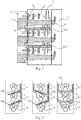
- Fig. 1 shows an example of a three phase switchgear or control gear, where for ease of reference the following features shown are listed:
- phase/breaker pole or disconnector switch e.g. phase L1
- phase L1 phase/breaker pole or disconnector switch
- the switchgear or control gear for operation in a low voltage, medium voltage or high voltage substation decribed with respect to Figs. 3-5 addresses these issues.
- One example relates to a switchgear or control gear comprising a first compartment 1, a first phase L1, a second phase L2, a third phase L3, and at least one air leading device 100, such as a plate.
- a circuit breaker (CB) pole 4 of the first phase L1 is housed in the first compartment.
- a CB pole can also be called a single interruption unit.
- a CB pole 4 of the second phase L2 is housed in the first compartment.
- a CB pole 4 of the third phase L3 is housed in the first compartment.
- the CB pole 4 of the second phase L2 is located above the CB pole 4 of the third phase L3.
- a first air leading device of the at least one air leading device 100 is located between the CB pole 4 of the second phase L2 and the CB pole 4 of the third phase L3.
- a three-position disconnector switch 3 of the first phase is housed in the first compartment
- a three-position disconnector switch 3 of the second phase is housed in the first compartment
- a three-position disconnector switch 3 of the third phase is housed in the first compartment.
- the three-position disconnector switch 3 of the second phase L2 is located above the three-position disconnector switch 3 of the third phase L3.
- the first air leading device is located between the there-position switch 3 of the second phase L2 and the three-position disconnector switch 3 of the third phase L3.
- the switchgear or control gear comprises at least one removable module 6, 7, a plurality of main switchgear or control gear components, and a plurality of auxiliary switchgear or control gear components.
- the plurality of main switchgear or control gear components are sub-divided into a first group of components and a second group of components.
- the plurality of auxiliary switchgear or control gear components are sub-divided into a first group of components and a second group of components.
- the plurality of main switchgear or control gear components in the first group of components and the plurality of auxiliary switchgear or control gear in the first group of components are housed in the first compartment.
- the plurality of main switchgear or control gear components in the second group of components and the plurality of auxiliary switchgear or control gear in the second group of components are housed in or associated with the at least one removable module. Removal of the at least one removable module from the switchgear or control gear is configured to remove the plurality of main switchgear or control gear components in the second group of components and the plurality of auxiliary switchgear or control gear in the second group of components from the switchgear or control gear. Thus, removal of the removable module allows or enables these components also to be removed from the switchgear of control gear.
- the plurality of main switchgear or control gear components in the second group of components and the plurality of auxiliary switchgear or control gear in the second group of components being housed or associated with the removable module does not necessarily mean that these components are totally enclosed within the removable module. But, being housed or associated with the removable module means that removal of the removable module from the switchgear or control gear also removes those components that are housed or associated with the removable module from the switchgear or control gear.
- the plurality of main switchgear or control gear components are sub-divided into the first group of components that have a lifetime greater than a threshold level and the second group of components that have a lifetime less than or equal to the threshold level.
- the plurality of auxiliary switchgear or control gear components are sub-divided into the first group of components that have a lifetime greater than the threshold level and the second group of components that have a lifetime less than or equal to the threshold level.
- the threshold for the main switchgear or control gear components can be the same as the threshold for the auxiliary switchgear or control gear components.
- the threshold can be determined in a number of different ways, for example being an average lifetime of components in the switchgear or control gear, or a time span equal to that between major scheduled system maintenance for example. Other time thresholds can be utilized.
- the terms “have a lifetime greater than a threshold” and “have a lifetime less than or equal to a threshold” here relate to an expected lifetime, that can be determined from prior experimental knowledge of components or from data sheets for example.
- the plurality of main switchgear or control gear components in the first group of components are fixedly housed in the first compartment.
- the plurality of auxiliary switchgear or control gear in the first group of components are fixedly housed in the first compartment.
- the plurality of main switchgear or control gear components in the second group of components and the plurality of auxiliary switchgear or control gear in the second group of components are divided into a plurality of logical groups, and wherein the components in a logical group are housed in or associated with the same removable module.
- a disconnector switch drive and auxiliaries are housed in or associated with the same removable module 6.
- the three-position disconnector switch 3 is a linear movement type switch or a rotational movement type switch.
- a CB control electronics and auxiliaries are housed in or associated with the same removable module 7.
- disconnector switch drive and auxiliaries are housed in or associated with a different removable module to the removable module within which the CB control electronics and auxiliaries are housed or associated.
- the removable module within which is housed or associated the CB control electronics and auxiliaries also houses or is associated with at least one part of a CB drive.
- An interface to a CB pole comprises a removable mechanical or electrical connection configured to transfer mechanical energy from the CB drive to a CB moving contact or electrical energy from the supply source to the CB drive.
- an electromagnetic drive or motor drive is provided, which is fixedly coupled to the CB pole.
- the coil windings of either of these drives then fall into the "First group of components”.
- the energy storage capacitor and/or the drive control electronics then fall into the "second group of components”.
- an electrical interface is sufficient, through for example a plug in the cable from the drive controller to the motor as part of a plug and socket functionality.
- a vacuum interrupter located in a central axis of the pole around the central axis is configured to act as a three position disconnector switch for connection, disconnection, and earthing.
- each phase of three phases has a same logical group, and wherein the logical group for each phase is housed in or associated with a different removable module.
- each phase of three phases has a same logical group, and wherein the logical group for each phase is housed in or associated with the same removable module.
- the first compartment (main compartment) is arc proof.
- each removable module of the at least one removable module comprises a plug and socket connection to supply and signal collection circuits, configured to enable communication with at least one component external to the removable module.
- the at least one removable module comprises at least one plug and socket connection.
- a plug and socket connection of the at least one plug and socket connection is configured for electrical connection between a CB drive electronics and a CB drive.
- the switchgear or control gear comprises at least one cable connection compartment 5 within which is housed at least part of at least one cable connection for at least one vacuum interrupter housed in the first compartment.
- At least one bushing forms part of the connection between the at least one cable connection and the at least one vacuum interrupter.
- the at least one bushing comprises current and voltage sensors or parts of voltage indication system.
- the at least one cable connection compartment comprises at least one door or removable wall section.
- a segregating wall between the first compartment and the at least one cable connection compartment is an arc proof segregation, enabling access of a user to the cable connection compartment when at least one component in the first compartment is operational.
- a different cable connection compartment is provided for each phase of three phases for a three phase system
- the plurality of main switchgear or control gear components in the first group of components and the plurality of auxiliary switchgear or control gear in the first group of components comprises one or more of: copper bars of a primary circuit; a CB pole with a vacuum interrupter (single interruption unit); post insulators; current and voltage sensors; air leading devices; and disconnector fixed contacts.
- the plurality of main switchgear or control gear components in the second group of components and the plurality of auxiliary switchgear or control gear in the second group of components comprises one or more of: electronic components for control and feedback collection; disconnector switch drive; CB control electronics; auxiliary switches; sensors for condition monitoring; cable terminations, and plug and socket systems.
- the air leading devices can thus be removed, or the air leading devices can be fixedly mounted within the first compartment.
- a primary circuit of the switchgear or control gear comprises one or more of: an earthing switch, voltage indication, surge arrestor, Ultra Fast Earthing Switch (UFES), IS-limiter (as invented by ABB Calor Emag in 1955), contactor, load-break switch, and fuse, and these components (and/or subcomponents of these components) when present are comprised within the second group of components of the plurality of main switchgear or control gear components or comprised within the second group of components of the plurality of auxiliary switchgear or control gear components.
- UFES Ultra Fast Earthing Switch
- IS-limiter as invented by ABB Calor Emag in 1955
- the removable module is configured to be removed from the switchgear and replaced with a different removable module of the same type.
- the reliability of the components in the first group is increased through utilization of the air leading devices described here, where lifetime and reliability are increased as the temperature rise of these components is reduced.
- the parts belonging to the first group can be designed as fixed (i.e. removable only with extra effort, tools or preparation) and not easily accessible for the maintenance systems or personnel - protected by the enclosure.
- the enclosure of the parts from the first group can be arc proof as it contains most of the primary circuit current carrying and insulating parts. But it does not have to be arc proof.
- the components belonging to the second group can be further sub grouped to logical subassemblies and encapsulated into removable modules.
- disconnector switch drive and auxiliaries can be enclosed into one module
- CB control electronics and auxiliaries can be enclosed into another module.
- Each of these removable modules has a plug and socket connection to the supply and signal collection circuits allowing communication with the rest of the switchgear.
- the first step of any maintenance action on the parts from second group is by replacing the module with parts that require maintenance with a spare module of the same type.
- the switchgear then can stay in operation or the down-time of the affected part of the switchgear can be limited to a minimum. Meanwhile the maintenance action itself on the parts in the replaced module can be postponed to a most suitable time and does not have to be carried out urgently.
- This compartment shall be preferably segregated with arc proof segregation from the inner room of the switchgear, and is separate for each feeder circuit and is accessible for human operators or maintainers. When all covers are properly closed this compartment is preferably arc proof and enclosed against the inner room of the switchgear as well as the outer space.
- the removable modules for the disconnector switch and the CB can be designed for each phase separately. These modules can however be designed as one module per all three phases or the three separate modules of the CB could be externally mechanically linked by e.g. toothbelt.
- a separate removable module is provided for the disconnector switch and for the CB. These modules can however be designed as one module for both the devices.
- the CB poles can include the current and voltage sensors.
- the sensors in a bushing can be a separate component connected to CB pole with a removable connection. Rather than having the sensors embedded into a bushing that is separate from the pole, the current and voltage sensors can be kept as stand alone devices located in the cable compartment and not integrated in the bushing.
- the disconnector switch is a linear movement type.
- a disconnector switch with rotational movement can be used as well.
- the removable module of the CB shown includes the control electronics and auxiliaries and allows simple electrical plug and socket connection to the CB drive.
- the module can also include parts of the CB drive and then the interface to the CB pole can be a removable mechanical connection transferring mechanical energy from the drive to the CB moving contact.
- the removable module can comprise the complete CB single pole unit (the pole including drive and auxiliaries). For that purpose it would be possible to use a rotational CB pole.
- the vacuum interrupter located in the central axis of the pole is then used for current interruption, while rotation of the pole around the central axis serves for connection, disconnection and earthing as three position disconnector switch.
- a removable cover of the cable termination compartment can be replaced with doors.
- the primary circuit of the switchgear or control gear can include other components and devices not described.
- the concept of separation of less reliable or shorter lifetime parts is applied to these components in that case.
- the removable module of the disconnector switch can embed the drive and auxiliaries only, or it can include the moving contact of the disconnector switch in as well.
- the CB pole 4 of the first phase L1 is located above the CB pole 4 of the second phase L2.
- a second air leading device of the at least one air leading device 100 is located between the CB pole 4 of the first phase L1 and the CB pole 4 of the second phase L2.
- the three-position disconnector switch 3 of the first phase L1 is located above the three-position disconnector switch 3 of the second phase L2.
- the second air leading device of the at least one air leading device is located between the three-position disconnector switch 3 of the first phase L1 and the three-position disconnector switch 3 of the second phase L2.
- the at least one air leading device is configured to direct rising gas and/or air toward at least one side wall of the first compartment.
- the first air leading device is configured to direct rising gas and/or air toward opposing side walls of the first compartment.
- the first air leading device is configured to direct rising gas and/or air toward a first side wall of the first compartment and the second air leading device is configured to direct rising gas and/or air toward a second opposing side wall of the first compartment.
- a longitudinal axis of the CB pole of the second phase is substantially horizontal and a longitudinal axis of CB pole of the third phase is substantially parallel to the longitudinal axis of the CB pole of the second phase.
- a longitudinal axis of the first air leading device is substantially parallel to the longitudinal axis of the CB pole of the second phase.
- At least one portion of the first air leading device is at an angle to the horizontal.
- the at least one portion of the first air leading device at an angle to the horizontal is angled in an axial direction perpendicular its longitudinal axis.
- a longitudinal axis of the CB pole of the first phase is substantially parallel to the longitudinal axis of the CB pole of the second phase.
- a longitudinal axis of the second air leading device is substantially parallel to the longitudinal axis of the CB pole of the second phase.
- At least one portion of the second air leading device is at an angle to the horizontal.
- the at least one portion of the second air leading device at an angle to the horizontal is angled in an axial direction perpendicular its longitudinal axis.
- the first air leading device has a same orientation to the second air leading device.
- the first air leading device is angled to the second air leading device.
- At least one outer surface of the at least one air leading device is ribbed.
- the at least one air leading device comprises one or more conduits, and wherein the one or more conduits are in fluid connection with a cooling system.
- the air leading devices of the at least one air leading device are air leading plates.
- the air leading device 100 such as a plate, has a length along longitudinal axis of a CB pole 4 that at least covers a distance from an earthing contact to the power incoming contact of the disconnector switch 3.
- the air leading device, or plate is located at the hottest area between the pole and disconnector.
- the air leading device, or plate does not necessarily need to be as long as the pole within the main compartment, rather it can provide for heat mitigation effects when it is as long as the disconnector within the main compartment.
- Fig. 3 shows a side view cross-section of the switchgear panel with air leading means or devices
- Fig. 4 showing the back view into the main compartment, with three possible arrangements of the air leading devices shown.
- the new development enables passive cooling of this switchgear (or control gear) configuration through a special arrangement inside of the switchgear, such that air flow from lower positioned parts or between parts is directed by air leading means to the side of the parts located above.
- the air leading devices or means 100 are located under the upper two poles/breakers, with a side inclination.
- the three-posiiton disconnector switches 3 and the CB pole 4 (which can also included an electromagnetic drive coil and current and voltage sensors) in each phase will not directly "see” the same parts 3 and 4 in other phases.
- heat radiation from lower parts will go into the air leading plate 100.
- De-warming then takes place from the air leading plate,
- the air leading plate can direct the airflow into a desired direction, nevertheless it can serve for other purposes as well as improving some other switchgear parameters.
- the surface of air leading plate can have longitudinal ribs, and in this way an enlarged area of the plate can serve also as a cooler itself. Longitudinal ribs can be on one side of the plate only, or also on both sides, as shwown in Fig.5 , where examples of such surface designs are presented.
- the air leading plates can be also elongated outside of the main panel area or even have internal tubes to enable the flow of a cooling medium from a connected separate cooling system located outside of the main panel area.
Landscapes
- Engineering & Computer Science (AREA)
- Power Engineering (AREA)
- Patch Boards (AREA)
Priority Applications (1)
| Application Number | Priority Date | Filing Date | Title |
|---|---|---|---|
| EP19181797.2A EP3754801B1 (de) | 2019-06-21 | 2019-06-21 | Schaltanlage oder steuergeräte |
Applications Claiming Priority (1)
| Application Number | Priority Date | Filing Date | Title |
|---|---|---|---|
| EP19181797.2A EP3754801B1 (de) | 2019-06-21 | 2019-06-21 | Schaltanlage oder steuergeräte |
Publications (2)
| Publication Number | Publication Date |
|---|---|
| EP3754801A1 true EP3754801A1 (de) | 2020-12-23 |
| EP3754801B1 EP3754801B1 (de) | 2023-03-08 |
Family
ID=67003219
Family Applications (1)
| Application Number | Title | Priority Date | Filing Date |
|---|---|---|---|
| EP19181797.2A Active EP3754801B1 (de) | 2019-06-21 | 2019-06-21 | Schaltanlage oder steuergeräte |
Country Status (1)
| Country | Link |
|---|---|
| EP (1) | EP3754801B1 (de) |
Cited By (1)
| Publication number | Priority date | Publication date | Assignee | Title |
|---|---|---|---|---|
| US20210305788A1 (en) * | 2018-12-19 | 2021-09-30 | Abb Schweiz Ag | Switchgear |
Citations (5)
| Publication number | Priority date | Publication date | Assignee | Title |
|---|---|---|---|---|
| JPS5561210A (en) * | 1978-10-31 | 1980-05-08 | Tokyo Shibaura Electric Co | Enclosed switchboard |
| EP0543352A1 (de) * | 1991-11-18 | 1993-05-26 | Hitachi, Ltd. | Schaltfeld |
| JPH10270880A (ja) * | 1997-03-28 | 1998-10-09 | Meidensha Corp | 配電盤 |
| JP2001112127A (ja) * | 1999-10-04 | 2001-04-20 | Meidensha Corp | ガス絶縁開閉装置 |
| US20170149217A1 (en) * | 2015-11-24 | 2017-05-25 | Abb Technology Ag | Switchgear Enclosure With Improved Venting |
-
2019
- 2019-06-21 EP EP19181797.2A patent/EP3754801B1/de active Active
Patent Citations (5)
| Publication number | Priority date | Publication date | Assignee | Title |
|---|---|---|---|---|
| JPS5561210A (en) * | 1978-10-31 | 1980-05-08 | Tokyo Shibaura Electric Co | Enclosed switchboard |
| EP0543352A1 (de) * | 1991-11-18 | 1993-05-26 | Hitachi, Ltd. | Schaltfeld |
| JPH10270880A (ja) * | 1997-03-28 | 1998-10-09 | Meidensha Corp | 配電盤 |
| JP2001112127A (ja) * | 1999-10-04 | 2001-04-20 | Meidensha Corp | ガス絶縁開閉装置 |
| US20170149217A1 (en) * | 2015-11-24 | 2017-05-25 | Abb Technology Ag | Switchgear Enclosure With Improved Venting |
Cited By (2)
| Publication number | Priority date | Publication date | Assignee | Title |
|---|---|---|---|---|
| US20210305788A1 (en) * | 2018-12-19 | 2021-09-30 | Abb Schweiz Ag | Switchgear |
| US11682885B2 (en) * | 2018-12-19 | 2023-06-20 | Abb Schweiz Ag | Switchgear |
Also Published As
| Publication number | Publication date |
|---|---|
| EP3754801B1 (de) | 2023-03-08 |
Similar Documents
| Publication | Publication Date | Title |
|---|---|---|
| RU2382459C1 (ru) | Устройство для контроля плавного пуска и остановки трехфазных электродвигателей (софтстартер) | |
| EP2979292B1 (de) | Schalteranordnung, schaltvorrichtung mit einer schalteranordnung, schaltgetriebe mit einer schaltvorrichtung und verfahren zum kühlen | |
| US11682885B2 (en) | Switchgear | |
| CN103460826A (zh) | 用于制造电能的设备的开关柜装置 | |
| JP5791832B2 (ja) | ガス絶縁スイッチギヤ | |
| EP2958205B1 (de) | Gasisolierte schaltanlage | |
| US11637414B2 (en) | Three phase switchgear using single phase equipment in single casing | |
| CN106061145B (zh) | 电动车电气部件总成 | |
| EP4318520A1 (de) | Halbleiter-schutzschalter | |
| EP3754801B1 (de) | Schaltanlage oder steuergeräte | |
| US6236562B1 (en) | Section of a high-voltage system having cooling means and including a conductor | |
| ES2865422T3 (es) | Dispositivo de conmutación con doble carcasa conductora | |
| JP2004072914A (ja) | 電力用遮断器 | |
| CN103165334B (zh) | 高电流开关装置 | |
| CN214013684U (zh) | 一种高压电流环保充气柜的高效散热结构 | |
| CN103166132B (zh) | 电气断开设备的通风装置 | |
| EP3671991B1 (de) | Dreiphasige schaltanlage | |
| CN222601746U (zh) | 汇流柜及储能系统 | |
| JPH1094120A (ja) | 金属閉鎖形スイッチギヤ | |
| CN205693992U (zh) | 电动车电气部件总成 | |
| CN218414125U (zh) | 一种有效散热的接地电阻柜 | |
| JP4519076B2 (ja) | ガス絶縁開閉装置 | |
| JPH01122306A (ja) | ガス絶縁開閉装置 | |
| CN221009638U (zh) | 气体绝缘开关设备 | |
| KR20200022662A (ko) | 일체형 특고압 수전장치 |
Legal Events
| Date | Code | Title | Description |
|---|---|---|---|
| PUAI | Public reference made under article 153(3) epc to a published international application that has entered the european phase |
Free format text: ORIGINAL CODE: 0009012 |
|
| STAA | Information on the status of an ep patent application or granted ep patent |
Free format text: STATUS: THE APPLICATION HAS BEEN PUBLISHED |
|
| AK | Designated contracting states |
Kind code of ref document: A1 Designated state(s): AL AT BE BG CH CY CZ DE DK EE ES FI FR GB GR HR HU IE IS IT LI LT LU LV MC MK MT NL NO PL PT RO RS SE SI SK SM TR |
|
| AX | Request for extension of the european patent |
Extension state: BA ME |
|
| STAA | Information on the status of an ep patent application or granted ep patent |
Free format text: STATUS: REQUEST FOR EXAMINATION WAS MADE |
|
| 17P | Request for examination filed |
Effective date: 20210526 |
|
| RBV | Designated contracting states (corrected) |
Designated state(s): AL AT BE BG CH CY CZ DE DK EE ES FI FR GB GR HR HU IE IS IT LI LT LU LV MC MK MT NL NO PL PT RO RS SE SI SK SM TR |
|
| GRAP | Despatch of communication of intention to grant a patent |
Free format text: ORIGINAL CODE: EPIDOSNIGR1 |
|
| STAA | Information on the status of an ep patent application or granted ep patent |
Free format text: STATUS: GRANT OF PATENT IS INTENDED |
|
| RIC1 | Information provided on ipc code assigned before grant |
Ipc: H02B 13/035 20060101ALN20220921BHEP Ipc: H02B 13/02 20060101ALN20220921BHEP Ipc: H02B 1/56 20060101AFI20220921BHEP |
|
| RIC1 | Information provided on ipc code assigned before grant |
Ipc: H02B 13/035 20060101ALN20221005BHEP Ipc: H02B 13/02 20060101ALN20221005BHEP Ipc: H02B 1/56 20060101AFI20221005BHEP |
|
| RIC1 | Information provided on ipc code assigned before grant |
Ipc: H02B 13/035 20060101ALN20221011BHEP Ipc: H02B 13/02 20060101ALN20221011BHEP Ipc: H02B 1/56 20060101AFI20221011BHEP |
|
| INTG | Intention to grant announced |
Effective date: 20221025 |
|
| GRAS | Grant fee paid |
Free format text: ORIGINAL CODE: EPIDOSNIGR3 |
|
| GRAA | (expected) grant |
Free format text: ORIGINAL CODE: 0009210 |
|
| STAA | Information on the status of an ep patent application or granted ep patent |
Free format text: STATUS: THE PATENT HAS BEEN GRANTED |
|
| RIN1 | Information on inventor provided before grant (corrected) |
Inventor name: STUPAK, MARCEL Inventor name: JERABEK, MICHAL Inventor name: SKUCI, MICHAL Inventor name: CERNOHOUS, JOSEF Inventor name: JAVORA, RADEK Inventor name: GENTSCH, DIETMAR |
|
| AK | Designated contracting states |
Kind code of ref document: B1 Designated state(s): AL AT BE BG CH CY CZ DE DK EE ES FI FR GB GR HR HU IE IS IT LI LT LU LV MC MK MT NL NO PL PT RO RS SE SI SK SM TR |
|
| RAP3 | Party data changed (applicant data changed or rights of an application transferred) |
Owner name: ABB SCHWEIZ AG |
|
| REG | Reference to a national code |
Ref country code: CH Ref legal event code: EP Ref country code: AT Ref legal event code: REF Ref document number: 1553226 Country of ref document: AT Kind code of ref document: T Effective date: 20230315 |
|
| REG | Reference to a national code |
Ref country code: IE Ref legal event code: FG4D |
|
| REG | Reference to a national code |
Ref country code: DE Ref legal event code: R096 Ref document number: 602019026063 Country of ref document: DE |
|
| REG | Reference to a national code |
Ref country code: LT Ref legal event code: MG9D |
|
| REG | Reference to a national code |
Ref country code: NL Ref legal event code: MP Effective date: 20230308 |
|
| PG25 | Lapsed in a contracting state [announced via postgrant information from national office to epo] |
Ref country code: RS Free format text: LAPSE BECAUSE OF FAILURE TO SUBMIT A TRANSLATION OF THE DESCRIPTION OR TO PAY THE FEE WITHIN THE PRESCRIBED TIME-LIMIT Effective date: 20230308 Ref country code: NO Free format text: LAPSE BECAUSE OF FAILURE TO SUBMIT A TRANSLATION OF THE DESCRIPTION OR TO PAY THE FEE WITHIN THE PRESCRIBED TIME-LIMIT Effective date: 20230608 Ref country code: LV Free format text: LAPSE BECAUSE OF FAILURE TO SUBMIT A TRANSLATION OF THE DESCRIPTION OR TO PAY THE FEE WITHIN THE PRESCRIBED TIME-LIMIT Effective date: 20230308 Ref country code: LT Free format text: LAPSE BECAUSE OF FAILURE TO SUBMIT A TRANSLATION OF THE DESCRIPTION OR TO PAY THE FEE WITHIN THE PRESCRIBED TIME-LIMIT Effective date: 20230308 Ref country code: HR Free format text: LAPSE BECAUSE OF FAILURE TO SUBMIT A TRANSLATION OF THE DESCRIPTION OR TO PAY THE FEE WITHIN THE PRESCRIBED TIME-LIMIT Effective date: 20230308 Ref country code: ES Free format text: LAPSE BECAUSE OF FAILURE TO SUBMIT A TRANSLATION OF THE DESCRIPTION OR TO PAY THE FEE WITHIN THE PRESCRIBED TIME-LIMIT Effective date: 20230308 |
|
| REG | Reference to a national code |
Ref country code: AT Ref legal event code: MK05 Ref document number: 1553226 Country of ref document: AT Kind code of ref document: T Effective date: 20230308 |
|
| PG25 | Lapsed in a contracting state [announced via postgrant information from national office to epo] |
Ref country code: SE Free format text: LAPSE BECAUSE OF FAILURE TO SUBMIT A TRANSLATION OF THE DESCRIPTION OR TO PAY THE FEE WITHIN THE PRESCRIBED TIME-LIMIT Effective date: 20230308 Ref country code: NL Free format text: LAPSE BECAUSE OF FAILURE TO SUBMIT A TRANSLATION OF THE DESCRIPTION OR TO PAY THE FEE WITHIN THE PRESCRIBED TIME-LIMIT Effective date: 20230308 Ref country code: GR Free format text: LAPSE BECAUSE OF FAILURE TO SUBMIT A TRANSLATION OF THE DESCRIPTION OR TO PAY THE FEE WITHIN THE PRESCRIBED TIME-LIMIT Effective date: 20230609 Ref country code: FI Free format text: LAPSE BECAUSE OF FAILURE TO SUBMIT A TRANSLATION OF THE DESCRIPTION OR TO PAY THE FEE WITHIN THE PRESCRIBED TIME-LIMIT Effective date: 20230308 |
|
| PG25 | Lapsed in a contracting state [announced via postgrant information from national office to epo] |
Ref country code: SM Free format text: LAPSE BECAUSE OF FAILURE TO SUBMIT A TRANSLATION OF THE DESCRIPTION OR TO PAY THE FEE WITHIN THE PRESCRIBED TIME-LIMIT Effective date: 20230308 Ref country code: RO Free format text: LAPSE BECAUSE OF FAILURE TO SUBMIT A TRANSLATION OF THE DESCRIPTION OR TO PAY THE FEE WITHIN THE PRESCRIBED TIME-LIMIT Effective date: 20230308 Ref country code: PT Free format text: LAPSE BECAUSE OF FAILURE TO SUBMIT A TRANSLATION OF THE DESCRIPTION OR TO PAY THE FEE WITHIN THE PRESCRIBED TIME-LIMIT Effective date: 20230710 Ref country code: EE Free format text: LAPSE BECAUSE OF FAILURE TO SUBMIT A TRANSLATION OF THE DESCRIPTION OR TO PAY THE FEE WITHIN THE PRESCRIBED TIME-LIMIT Effective date: 20230308 Ref country code: CZ Free format text: LAPSE BECAUSE OF FAILURE TO SUBMIT A TRANSLATION OF THE DESCRIPTION OR TO PAY THE FEE WITHIN THE PRESCRIBED TIME-LIMIT Effective date: 20230308 Ref country code: AT Free format text: LAPSE BECAUSE OF FAILURE TO SUBMIT A TRANSLATION OF THE DESCRIPTION OR TO PAY THE FEE WITHIN THE PRESCRIBED TIME-LIMIT Effective date: 20230308 |
|
| PG25 | Lapsed in a contracting state [announced via postgrant information from national office to epo] |
Ref country code: SK Free format text: LAPSE BECAUSE OF FAILURE TO SUBMIT A TRANSLATION OF THE DESCRIPTION OR TO PAY THE FEE WITHIN THE PRESCRIBED TIME-LIMIT Effective date: 20230308 Ref country code: PL Free format text: LAPSE BECAUSE OF FAILURE TO SUBMIT A TRANSLATION OF THE DESCRIPTION OR TO PAY THE FEE WITHIN THE PRESCRIBED TIME-LIMIT Effective date: 20230308 Ref country code: IS Free format text: LAPSE BECAUSE OF FAILURE TO SUBMIT A TRANSLATION OF THE DESCRIPTION OR TO PAY THE FEE WITHIN THE PRESCRIBED TIME-LIMIT Effective date: 20230708 |
|
| REG | Reference to a national code |
Ref country code: DE Ref legal event code: R097 Ref document number: 602019026063 Country of ref document: DE |
|
| PLBE | No opposition filed within time limit |
Free format text: ORIGINAL CODE: 0009261 |
|
| STAA | Information on the status of an ep patent application or granted ep patent |
Free format text: STATUS: NO OPPOSITION FILED WITHIN TIME LIMIT |
|
| PG25 | Lapsed in a contracting state [announced via postgrant information from national office to epo] |
Ref country code: MC Free format text: LAPSE BECAUSE OF FAILURE TO SUBMIT A TRANSLATION OF THE DESCRIPTION OR TO PAY THE FEE WITHIN THE PRESCRIBED TIME-LIMIT Effective date: 20230308 |
|
| PG25 | Lapsed in a contracting state [announced via postgrant information from national office to epo] |
Ref country code: SI Free format text: LAPSE BECAUSE OF FAILURE TO SUBMIT A TRANSLATION OF THE DESCRIPTION OR TO PAY THE FEE WITHIN THE PRESCRIBED TIME-LIMIT Effective date: 20230308 Ref country code: MC Free format text: LAPSE BECAUSE OF FAILURE TO SUBMIT A TRANSLATION OF THE DESCRIPTION OR TO PAY THE FEE WITHIN THE PRESCRIBED TIME-LIMIT Effective date: 20230308 Ref country code: DK Free format text: LAPSE BECAUSE OF FAILURE TO SUBMIT A TRANSLATION OF THE DESCRIPTION OR TO PAY THE FEE WITHIN THE PRESCRIBED TIME-LIMIT Effective date: 20230308 |
|
| REG | Reference to a national code |
Ref country code: CH Ref legal event code: PL |
|
| 26N | No opposition filed |
Effective date: 20231211 |
|
| REG | Reference to a national code |
Ref country code: BE Ref legal event code: MM Effective date: 20230630 |
|
| GBPC | Gb: european patent ceased through non-payment of renewal fee |
Effective date: 20230621 |
|
| PG25 | Lapsed in a contracting state [announced via postgrant information from national office to epo] |
Ref country code: LU Free format text: LAPSE BECAUSE OF NON-PAYMENT OF DUE FEES Effective date: 20230621 |
|
| REG | Reference to a national code |
Ref country code: IE Ref legal event code: MM4A |
|
| PG25 | Lapsed in a contracting state [announced via postgrant information from national office to epo] |
Ref country code: LU Free format text: LAPSE BECAUSE OF NON-PAYMENT OF DUE FEES Effective date: 20230621 |
|
| PG25 | Lapsed in a contracting state [announced via postgrant information from national office to epo] |
Ref country code: IE Free format text: LAPSE BECAUSE OF NON-PAYMENT OF DUE FEES Effective date: 20230621 |
|
| PG25 | Lapsed in a contracting state [announced via postgrant information from national office to epo] |
Ref country code: IE Free format text: LAPSE BECAUSE OF NON-PAYMENT OF DUE FEES Effective date: 20230621 Ref country code: CH Free format text: LAPSE BECAUSE OF NON-PAYMENT OF DUE FEES Effective date: 20230630 Ref country code: GB Free format text: LAPSE BECAUSE OF NON-PAYMENT OF DUE FEES Effective date: 20230621 |
|
| PG25 | Lapsed in a contracting state [announced via postgrant information from national office to epo] |
Ref country code: BE Free format text: LAPSE BECAUSE OF NON-PAYMENT OF DUE FEES Effective date: 20230630 |
|
| PG25 | Lapsed in a contracting state [announced via postgrant information from national office to epo] |
Ref country code: BG Free format text: LAPSE BECAUSE OF FAILURE TO SUBMIT A TRANSLATION OF THE DESCRIPTION OR TO PAY THE FEE WITHIN THE PRESCRIBED TIME-LIMIT Effective date: 20230308 |
|
| PG25 | Lapsed in a contracting state [announced via postgrant information from national office to epo] |
Ref country code: BG Free format text: LAPSE BECAUSE OF FAILURE TO SUBMIT A TRANSLATION OF THE DESCRIPTION OR TO PAY THE FEE WITHIN THE PRESCRIBED TIME-LIMIT Effective date: 20230308 |
|
| PGFP | Annual fee paid to national office [announced via postgrant information from national office to epo] |
Ref country code: DE Payment date: 20250618 Year of fee payment: 7 |
|
| PGFP | Annual fee paid to national office [announced via postgrant information from national office to epo] |
Ref country code: FR Payment date: 20250626 Year of fee payment: 7 |
|
| PG25 | Lapsed in a contracting state [announced via postgrant information from national office to epo] |
Ref country code: CY Free format text: LAPSE BECAUSE OF FAILURE TO SUBMIT A TRANSLATION OF THE DESCRIPTION OR TO PAY THE FEE WITHIN THE PRESCRIBED TIME-LIMIT; INVALID AB INITIO Effective date: 20190621 |
|
| PG25 | Lapsed in a contracting state [announced via postgrant information from national office to epo] |
Ref country code: HU Free format text: LAPSE BECAUSE OF FAILURE TO SUBMIT A TRANSLATION OF THE DESCRIPTION OR TO PAY THE FEE WITHIN THE PRESCRIBED TIME-LIMIT; INVALID AB INITIO Effective date: 20190621 |
|
| PGFP | Annual fee paid to national office [announced via postgrant information from national office to epo] |
Ref country code: IT Payment date: 20250624 Year of fee payment: 7 |
|
| PG25 | Lapsed in a contracting state [announced via postgrant information from national office to epo] |
Ref country code: TR Free format text: LAPSE BECAUSE OF FAILURE TO SUBMIT A TRANSLATION OF THE DESCRIPTION OR TO PAY THE FEE WITHIN THE PRESCRIBED TIME-LIMIT Effective date: 20230308 |