EP3754750B1 - Venting device - Google Patents
Venting device Download PDFInfo
- Publication number
- EP3754750B1 EP3754750B1 EP19916644.8A EP19916644A EP3754750B1 EP 3754750 B1 EP3754750 B1 EP 3754750B1 EP 19916644 A EP19916644 A EP 19916644A EP 3754750 B1 EP3754750 B1 EP 3754750B1
- Authority
- EP
- European Patent Office
- Prior art keywords
- plate spring
- sheet
- venting device
- pouch
- ball
- Prior art date
- Legal status (The legal status is an assumption and is not a legal conclusion. Google has not performed a legal analysis and makes no representation as to the accuracy of the status listed.)
- Active
Links
- 238000013022 venting Methods 0.000 title claims description 63
- 238000007789 sealing Methods 0.000 claims description 42
- 229910052751 metal Inorganic materials 0.000 claims description 19
- 239000002184 metal Substances 0.000 claims description 19
- 238000003780 insertion Methods 0.000 claims description 12
- 230000037431 insertion Effects 0.000 claims description 12
- 230000002093 peripheral effect Effects 0.000 claims description 9
- 238000003860 storage Methods 0.000 claims description 4
- 239000007789 gas Substances 0.000 description 50
- 239000010410 layer Substances 0.000 description 38
- 239000000463 material Substances 0.000 description 22
- -1 polyethylene Polymers 0.000 description 15
- 239000000565 sealant Substances 0.000 description 15
- 239000003792 electrolyte Substances 0.000 description 12
- 230000004888 barrier function Effects 0.000 description 11
- 238000004519 manufacturing process Methods 0.000 description 11
- 239000004743 Polypropylene Substances 0.000 description 9
- 229920000642 polymer Polymers 0.000 description 9
- 229920001155 polypropylene Polymers 0.000 description 9
- 238000000034 method Methods 0.000 description 8
- 230000004308 accommodation Effects 0.000 description 7
- 229910052782 aluminium Inorganic materials 0.000 description 7
- 238000009413 insulation Methods 0.000 description 7
- XAGFODPZIPBFFR-UHFFFAOYSA-N aluminium Chemical compound [Al] XAGFODPZIPBFFR-UHFFFAOYSA-N 0.000 description 6
- 238000005452 bending Methods 0.000 description 5
- 239000007772 electrode material Substances 0.000 description 5
- PXHVJJICTQNCMI-UHFFFAOYSA-N Nickel Chemical compound [Ni] PXHVJJICTQNCMI-UHFFFAOYSA-N 0.000 description 4
- 239000004698 Polyethylene Substances 0.000 description 4
- 230000007423 decrease Effects 0.000 description 4
- 238000010586 diagram Methods 0.000 description 4
- 230000000694 effects Effects 0.000 description 4
- 229920000573 polyethylene Polymers 0.000 description 4
- 229920000139 polyethylene terephthalate Polymers 0.000 description 4
- 239000005020 polyethylene terephthalate Substances 0.000 description 4
- HBBGRARXTFLTSG-UHFFFAOYSA-N Lithium ion Chemical compound [Li+] HBBGRARXTFLTSG-UHFFFAOYSA-N 0.000 description 3
- 239000004677 Nylon Substances 0.000 description 3
- 230000008901 benefit Effects 0.000 description 3
- 239000011248 coating agent Substances 0.000 description 3
- 238000000576 coating method Methods 0.000 description 3
- 239000010949 copper Substances 0.000 description 3
- 238000003487 electrochemical reaction Methods 0.000 description 3
- XEEYBQQBJWHFJM-UHFFFAOYSA-N iron Substances [Fe] XEEYBQQBJWHFJM-UHFFFAOYSA-N 0.000 description 3
- 229910001416 lithium ion Inorganic materials 0.000 description 3
- 229920001778 nylon Polymers 0.000 description 3
- 239000004417 polycarbonate Substances 0.000 description 3
- 239000002002 slurry Substances 0.000 description 3
- RYGMFSIKBFXOCR-UHFFFAOYSA-N Copper Chemical compound [Cu] RYGMFSIKBFXOCR-UHFFFAOYSA-N 0.000 description 2
- 239000004952 Polyamide Substances 0.000 description 2
- 239000004642 Polyimide Substances 0.000 description 2
- 239000004809 Teflon Substances 0.000 description 2
- 229920006362 Teflon® Polymers 0.000 description 2
- 238000005299 abrasion Methods 0.000 description 2
- 239000011149 active material Substances 0.000 description 2
- 239000000853 adhesive Substances 0.000 description 2
- 230000001070 adhesive effect Effects 0.000 description 2
- 239000004760 aramid Substances 0.000 description 2
- 229920003235 aromatic polyamide Polymers 0.000 description 2
- 239000011230 binding agent Substances 0.000 description 2
- 229920002678 cellulose Polymers 0.000 description 2
- 239000001913 cellulose Substances 0.000 description 2
- 239000002131 composite material Substances 0.000 description 2
- 229910052802 copper Inorganic materials 0.000 description 2
- 238000005260 corrosion Methods 0.000 description 2
- 230000007797 corrosion Effects 0.000 description 2
- 238000000354 decomposition reaction Methods 0.000 description 2
- 238000007599 discharging Methods 0.000 description 2
- 230000005611 electricity Effects 0.000 description 2
- 238000004146 energy storage Methods 0.000 description 2
- 239000011888 foil Substances 0.000 description 2
- 239000003365 glass fiber Substances 0.000 description 2
- 229910052742 iron Inorganic materials 0.000 description 2
- 239000000203 mixture Substances 0.000 description 2
- 229910052759 nickel Inorganic materials 0.000 description 2
- 239000004014 plasticizer Substances 0.000 description 2
- 229920000058 polyacrylate Polymers 0.000 description 2
- 229920002239 polyacrylonitrile Polymers 0.000 description 2
- 229920002647 polyamide Polymers 0.000 description 2
- 229920001230 polyarylate Polymers 0.000 description 2
- 229920000515 polycarbonate Polymers 0.000 description 2
- 229920000728 polyester Polymers 0.000 description 2
- 229920001721 polyimide Polymers 0.000 description 2
- 229920000915 polyvinyl chloride Polymers 0.000 description 2
- 239000004800 polyvinyl chloride Substances 0.000 description 2
- 239000002356 single layer Substances 0.000 description 2
- 239000002904 solvent Substances 0.000 description 2
- 229910001220 stainless steel Inorganic materials 0.000 description 2
- 239000010935 stainless steel Substances 0.000 description 2
- 238000003466 welding Methods 0.000 description 2
- 229910052799 carbon Inorganic materials 0.000 description 1
- 229910052804 chromium Inorganic materials 0.000 description 1
- 230000000295 complement effect Effects 0.000 description 1
- 230000006835 compression Effects 0.000 description 1
- 238000007906 compression Methods 0.000 description 1
- 239000004020 conductor Substances 0.000 description 1
- 238000005520 cutting process Methods 0.000 description 1
- 238000004880 explosion Methods 0.000 description 1
- 229920005570 flexible polymer Polymers 0.000 description 1
- 230000017525 heat dissipation Effects 0.000 description 1
- 230000020169 heat generation Effects 0.000 description 1
- 229910052739 hydrogen Inorganic materials 0.000 description 1
- 239000001257 hydrogen Substances 0.000 description 1
- 235000015110 jellies Nutrition 0.000 description 1
- 239000008274 jelly Substances 0.000 description 1
- 229910003002 lithium salt Inorganic materials 0.000 description 1
- 159000000002 lithium salts Chemical class 0.000 description 1
- 229910052748 manganese Inorganic materials 0.000 description 1
- 238000000465 moulding Methods 0.000 description 1
- 239000000615 nonconductor Substances 0.000 description 1
- 239000005486 organic electrolyte Substances 0.000 description 1
- 239000003960 organic solvent Substances 0.000 description 1
- 229920003023 plastic Polymers 0.000 description 1
- 239000004033 plastic Substances 0.000 description 1
- 229920001690 polydopamine Polymers 0.000 description 1
- 239000005518 polymer electrolyte Substances 0.000 description 1
- 239000002861 polymer material Substances 0.000 description 1
- 229920000098 polyolefin Polymers 0.000 description 1
- 229920005672 polyolefin resin Polymers 0.000 description 1
- 229920005989 resin Polymers 0.000 description 1
- 239000011347 resin Substances 0.000 description 1
- 238000000926 separation method Methods 0.000 description 1
- 239000000126 substance Substances 0.000 description 1
- 230000003746 surface roughness Effects 0.000 description 1
- 229920001897 terpolymer Polymers 0.000 description 1
- 230000003313 weakening effect Effects 0.000 description 1
Images


Classifications
-
- H—ELECTRICITY
- H01—ELECTRIC ELEMENTS
- H01M—PROCESSES OR MEANS, e.g. BATTERIES, FOR THE DIRECT CONVERSION OF CHEMICAL ENERGY INTO ELECTRICAL ENERGY
- H01M50/00—Constructional details or processes of manufacture of the non-active parts of electrochemical cells other than fuel cells, e.g. hybrid cells
- H01M50/30—Arrangements for facilitating escape of gases
- H01M50/317—Re-sealable arrangements
- H01M50/325—Re-sealable arrangements comprising deformable valve members, e.g. elastic or flexible valve members
- H01M50/333—Spring-loaded vent valves
-
- H—ELECTRICITY
- H01—ELECTRIC ELEMENTS
- H01M—PROCESSES OR MEANS, e.g. BATTERIES, FOR THE DIRECT CONVERSION OF CHEMICAL ENERGY INTO ELECTRICAL ENERGY
- H01M50/00—Constructional details or processes of manufacture of the non-active parts of electrochemical cells other than fuel cells, e.g. hybrid cells
- H01M50/10—Primary casings, jackets or wrappings of a single cell or a single battery
- H01M50/102—Primary casings, jackets or wrappings of a single cell or a single battery characterised by their shape or physical structure
- H01M50/105—Pouches or flexible bags
-
- H—ELECTRICITY
- H01—ELECTRIC ELEMENTS
- H01M—PROCESSES OR MEANS, e.g. BATTERIES, FOR THE DIRECT CONVERSION OF CHEMICAL ENERGY INTO ELECTRICAL ENERGY
- H01M50/00—Constructional details or processes of manufacture of the non-active parts of electrochemical cells other than fuel cells, e.g. hybrid cells
- H01M50/10—Primary casings, jackets or wrappings of a single cell or a single battery
- H01M50/102—Primary casings, jackets or wrappings of a single cell or a single battery characterised by their shape or physical structure
- H01M50/107—Primary casings, jackets or wrappings of a single cell or a single battery characterised by their shape or physical structure having curved cross-section, e.g. round or elliptic
-
- H—ELECTRICITY
- H01—ELECTRIC ELEMENTS
- H01M—PROCESSES OR MEANS, e.g. BATTERIES, FOR THE DIRECT CONVERSION OF CHEMICAL ENERGY INTO ELECTRICAL ENERGY
- H01M50/00—Constructional details or processes of manufacture of the non-active parts of electrochemical cells other than fuel cells, e.g. hybrid cells
- H01M50/30—Arrangements for facilitating escape of gases
- H01M50/317—Re-sealable arrangements
- H01M50/325—Re-sealable arrangements comprising deformable valve members, e.g. elastic or flexible valve members
-
- H—ELECTRICITY
- H01—ELECTRIC ELEMENTS
- H01M—PROCESSES OR MEANS, e.g. BATTERIES, FOR THE DIRECT CONVERSION OF CHEMICAL ENERGY INTO ELECTRICAL ENERGY
- H01M50/00—Constructional details or processes of manufacture of the non-active parts of electrochemical cells other than fuel cells, e.g. hybrid cells
- H01M50/30—Arrangements for facilitating escape of gases
- H01M50/35—Gas exhaust passages comprising elongated, tortuous or labyrinth-shaped exhaust passages
-
- H—ELECTRICITY
- H01—ELECTRIC ELEMENTS
- H01M—PROCESSES OR MEANS, e.g. BATTERIES, FOR THE DIRECT CONVERSION OF CHEMICAL ENERGY INTO ELECTRICAL ENERGY
- H01M2220/00—Batteries for particular applications
- H01M2220/10—Batteries in stationary systems, e.g. emergency power source in plant
-
- H—ELECTRICITY
- H01—ELECTRIC ELEMENTS
- H01M—PROCESSES OR MEANS, e.g. BATTERIES, FOR THE DIRECT CONVERSION OF CHEMICAL ENERGY INTO ELECTRICAL ENERGY
- H01M2220/00—Batteries for particular applications
- H01M2220/20—Batteries in motive systems, e.g. vehicle, ship, plane
-
- H—ELECTRICITY
- H01—ELECTRIC ELEMENTS
- H01M—PROCESSES OR MEANS, e.g. BATTERIES, FOR THE DIRECT CONVERSION OF CHEMICAL ENERGY INTO ELECTRICAL ENERGY
- H01M2220/00—Batteries for particular applications
- H01M2220/30—Batteries in portable systems, e.g. mobile phone, laptop
-
- Y—GENERAL TAGGING OF NEW TECHNOLOGICAL DEVELOPMENTS; GENERAL TAGGING OF CROSS-SECTIONAL TECHNOLOGIES SPANNING OVER SEVERAL SECTIONS OF THE IPC; TECHNICAL SUBJECTS COVERED BY FORMER USPC CROSS-REFERENCE ART COLLECTIONS [XRACs] AND DIGESTS
- Y02—TECHNOLOGIES OR APPLICATIONS FOR MITIGATION OR ADAPTATION AGAINST CLIMATE CHANGE
- Y02E—REDUCTION OF GREENHOUSE GAS [GHG] EMISSIONS, RELATED TO ENERGY GENERATION, TRANSMISSION OR DISTRIBUTION
- Y02E60/00—Enabling technologies; Technologies with a potential or indirect contribution to GHG emissions mitigation
- Y02E60/10—Energy storage using batteries
Definitions
- the present invention relates to a venting device, and more particularly, to at least one venting device,which is inserted into a sealing part of a pouch of a secondary battery to discharge a gas within the pouch to the outside and minimize bending of a plate spring in a closed state.
- secondary batteries include nickelcadmium batteries, nickel-hydrogen batteries, lithium ion batteries, and lithium ion polymer batteries.
- Such a secondary battery is being applied to and used in small-sized products such as digital cameras, P-DVDs, MP3Ps, mobile phones, PDAs, portable game devices, power tools, E-bikes, and the like as well as large-sized products requiring high power such as electric vehicles and hybrid vehicles, power storage devices for storing surplus power or renewable energy, and backup power storage devices.
- Such a secondary battery is classified into a pouch type secondary battery and a can type secondary battery according to a material of a case accommodating the electrode assembly.
- a pouch type secondary battery an electrode assembly is accommodated in a pouch made of a flexible polymer material.
- an electrode assembly is accommodated in a case made of a metal or plastic material.
- the secondary battery may be deteriorated in safety due to various problems such as internal short circuit due to an external impact, heat generation due to overcharging and overdischarging, electrolyte decomposition due to the generated heat, and a thermal runaway phenomenon. Particularly, when a gas is generated due to decomposition of an electrolyte to increase in pressure within the secondary battery, a problem occurs that the secondary battery is exploded.
- a gas is generated by electrochemical reaction between the electrolyte and an electrode active material.
- the generated gas may allow the secondary battery to increase in internal pressure to cause problems such as weakening of bonding force between components, damage of a case of the secondary battery, an early operation of a protection circuit, deformation of an electrode, internal short circuit, explosion, and the like.
- a protection member such as a CID filter and a safety vent is provided to physically interrupt an electrical connection when an internal pressure of a case increases.
- the protection member is not sufficiently provided.
- WO2015/160134 relates to safety valve for energy storage apparatus comprising a body composed of a first structure having a jet hole formed at one side thereof, and a second structure having a hole formed at one side thereof and integrally combined with the first structure; and a pair of elastic bodies arranged inside the first structure and operating in response to pressure.
- the present invention comprises: a body composed of a first structure and a second structure; a lift body arranged inside the first structure and operating in response to pressure; and a guide member arranged on the lift body and guiding movement of the lift body.
- the present invention as above, has an advantage of smoothly discharging gases generated from an energy storage apparatus while minimizing the volume of a safety valve by applying a simple structure such as a pair of elastic bodies or the lift body.
- JP2006313715 discloses a valve seat having a valve hole formed at the inner circumference is formed at a pressure release port of a sealing plate, a valve main body having a seal lip which contacts the valve seat with a prescribed face pressure and performs valve-opening operation with a prescribed inner pressure and a base part at the inner circumference is arranged at this pressure release port, and the base part is supported to a support member which is fixed to the pressure release port at the outside of the valve main body and through which a gas can pass, and the valve hole and the inner circumference space of the seal lip are communicated.
- An object of the present invention is to provide at least one venting device, which is inserted into a sealing part of a pouch of a secondary battery to discharge a gas within the pouch to the outside and minimize bending of a plate spring in a closed state.
- the invention is a venting device, which is inserted into a sealing part of a pouch of a secondary battery, according to the present invention for solving the above problem includes: a housing inserted between both surfaces of the sealing part so as to be sealed together with the sealing part; a sheet which is formed in the housing and through which a passage, through which the inside and outside of the pouch communicate with each other, passes; a plate spring which opens and closes the passage according to an internal pressure of the pouch and is made of made of a metal having elasticity; and a ball disposed between the sheet and the plate spring so as to contact or be spaced apart from the sheet at an outlet-side of the passage, thereby closing or opening the passage, wherein the ball has a hemispherical shape to be attached to an inner surface of the plate spring.
- the plate spring may include: a central portion formed at a center thereof; and a peripheral portion extending outward from the central portion, wherein the ball may be attached to the central portion, and a gas exhaust hole may be punched in the peripheral portion.
- the plate spring has one side having a cap shape that is convex outward and provide an insertion space into which the sheet and the ball are inserted therein.
- an end of the other side of the plate spring may be bent toward the sheet inserted into the insertion space.
- the plate spring may have a flat plate shape and contact the sheet.
- an edge of an inner circumference of a surface of the outlet-side of the passage may be chamfered or filleted.
- an edge of an inner circumference of the surface of the outlet-side of the passage may be chamfered or filleted.
- the housing may include an upper housing and a lower housing, which have shapes or sizes different from each other.
- the lower housing may have a width less than that of the upper housing.
- the upper housing may have a circular cylinder shape
- the lower housing may have an oval cylinder shape
- the present invention provides a pouch type secondary battery in which the venting device is inserted into a sealing part of a pouch, a battery module including the pouch type secondary battery as a unit cell, and a device including the battery module.
- the device may include a computer, a notebook, a smart phone, a mobile phone, a tablet PC, a wearable electronic device, a power tool, an electric vehicle (EV), a hybrid electric vehicle (HEV), a plug-in hybrid electric vehicle (PHEV), or a power storage device, but is not limited thereto.
- a computer a notebook, a smart phone, a mobile phone, a tablet PC, a wearable electronic device, a power tool, an electric vehicle (EV), a hybrid electric vehicle (HEV), a plug-in hybrid electric vehicle (PHEV), or a power storage device, but is not limited thereto.
- EV electric vehicle
- HEV hybrid electric vehicle
- PHEV plug-in hybrid electric vehicle
- a power storage device but is not limited thereto.
- the embodiments of the present invention may have at least the following effects.
- the bending of the plate spring may be minimized in the state in which the venting devices are closed to reduce the deviation in opening pressure between the venting devices.
- the deviation between the numerical value of the opening pressure, which is designed before manufacturing the venting device, and the actual opening pressure may be reduced.
- FIG. 1 is an assembled view of a secondary battery 1 including a venting device 15 according to an embodiment of the present invention
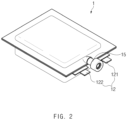
- FIG. 2 is a perspective view of the secondary battery 1 of FIG. 1 , which is completely manufactured.
- a process of manufacturing a pouch type secondary battery 1 first, slurry in which an electrode active material, a binder, and a plasticizer are mixed with each other is applied to a positive electrode collector and a negative electrode collector to manufacture electrodes such as a positive electrode and a negative electrode. Thereafter, the negative electrode and the positive electrode are respectively stacked on both sides of a separator to form an electrode assembly 10 having a predetermined shape, and then, the electrode assembly 10 is inserted into a battery case 13, an electrolyte is injected, and sealing is performed.
- the electrode assembly 10 includes two types of electrodes, such as the positive electrode and the negative electrode, and the separator interposed between the electrodes to insulate the electrodes from each other.
- the electrode assembly 10 may be a stack type, a jelly roll type, a stacked and folding type, or the like.
- Each of the two types of electrodes, i.e., the positive electrode and the negative electrode has a structure in which active material slurry is applied to the electrode collector having a metal foil or metal mesh shape.
- the slurry may be usually formed by agitating a granular active material, an auxiliary conductor, a binder, and a plasticizer with a solvent added. The solvent may be removed in the subsequent process.
- the electrode assembly 10 includes an electrode tab 11.
- the electrode tab 11 protrudes from each of the positive electrode and the negative electrode of the electrode assembly 10 to provide a path, through which electrons move, between the inside and outside of the electrode assembly 10.
- a collector of the electrode assembly 10 is constituted by a portion coated with an electrode active material and a distal end, on which the electrode active material is not applied, i.e., a non-coating portion.
- the electrode tab 11 may be formed by cutting the non-coating portion or by connecting a separate conductive member to the non-coating portion through ultrasonic welding.
- the electrode tabs 11 may protrude from one side of the electrode assembly 10 in the same direction, but the present invention is not limited thereto.
- the electrode tabs 11 may protrude in directions different from each other.
- the electrode lead 12 is connected to the electrode tab 11 through spot welding. Also, a portion of the electrode lead 12 is surrounded by an insulation part 14.
- An insulation part 14 may be disposed to be limited within a sealing part 134, at which an upper case 131 and a lower case 132 of the battery case 13 are thermally fused, so as to be bonded to the battery case 13. Also, electricity generated from the electrode assembly 10 may be prevented from flowing to the battery case 13 through the electrode lead 12, and the sealing of the battery case 13 may be maintained.
- the insulation part 14 may be made of a nonconductor having non-conductivity, which is not electrically conductive.
- the present invention is not limited thereto.
- various members may be used as the insulation part 14 as long as the members are capable of insulating the electrode lead 12.
- the electrode lead 12 includes a positive electrode lead 121 having one end connected to a positive electrode tab 111 to extend in a direction in which the positive electrode tab 111 protrudes and a negative electrode lead 122 having one end connected to a negative electrode tab 112 to extend in a direction in which the negative electrode tab 112 protrudes.
- a positive electrode lead 121 having one end connected to a positive electrode tab 111 to extend in a direction in which the positive electrode tab 111 protrudes
- a negative electrode lead 122 having one end connected to a negative electrode tab 112 to extend in a direction in which the negative electrode tab 112 protrudes.
- all of the other ends of the positive electrode lead 121 and the negative electrode lead 122 protrude to the outside of the battery case 13.
- electricity generated in the electrode assembly 10 may be supplied to the outside.
- each of the positive electrode tab 111 and the negative electrode tab 112 is formed to protrude in various directions, each of the positive electrode lead 121 and the negative electrode lead 122 may extend in various directions.
- the positive electrode lead 121 and the negative electrode lead 122 may be made of materials different from each other. That is, the positive electrode lead 121 may be made of the same material as the positive current collector, i.e., an aluminum (Al) material, and the negative electrode lead 122 may be made of the same material as the negative current collector, i.e., a copper (Cu) material or a copper material coated with nickel (Ni). Also, a portion of the electrode lead 12, which protrudes to the outside of the battery case 13, may be provided as a terminal part and electrically connected to an external terminal.
- Al aluminum
- the negative electrode lead 122 may be made of the same material as the negative current collector, i.e., a copper (Cu) material or a copper material coated with nickel (Ni).
- a portion of the electrode lead 12, which protrudes to the outside of the battery case 13 may be provided as a terminal part and electrically connected to an external terminal.
- the battery case 13 is a pouch made of a flexible material. Hereinafter, the case in which the battery case 13 is the pouch will be described.
- the battery case 13 accommodates the electrode assembly 10 so that a portion of the electrode lead 12, i.e., the terminal part is exposed and then is sealed.
- the battery case 13 includes the upper case 131 and the lower case 132.
- a cup part 133 having an accommodation space 1331 accommodating the electrode assembly 10 is formed in the lower case 132, and upper case 131 may cover an upper side of the accommodation space 1331 so that the electrode assembly 10 is not separated to the outside of the battery case 13.
- FIG. 1 the battery case 13 accommodates the electrode assembly 10 so that a portion of the electrode lead 12, i.e., the terminal part is exposed and then is sealed.
- the battery case 13 includes the upper case 131 and the lower case 132.
- a cup part 133 having an accommodation space 1331 accommodating the electrode assembly 10 is formed in the lower case 132, and upper case 131 may cover an upper side of the accommodation space 1331
- the cup part 133 having the accommodation space 1331 may be formed in the upper case 131 to accommodate the electrode assembly 10 in the upper portion.
- one side of the upper case 131 and one side of the lower case 132 may be connected to each other.
- the present invention is not limited thereto.
- the upper case 131 and the lower case 132 may be separately manufactured to be separated from each other.
- the sealing part 134 formed on an edge may be sealed.
- the venting device 15 is inserted between both surfaces of the sealing part 134 so as to be sealed together with the sealing part 134 and thus be fixed within the sealing part 134.
- the venting device 15 includes a passage through which the inside and the outside of the battery case 13 communicate with each other. When an internal pressure of the battery case 13 increases, an internal gas is discharged to the outside to adjust the pressure. The venting device 15 will be described below in detail.
- the electrode assembly 10 When an electrode lead 12 is connected to the electrode tab 11 of the electrode assembly 10, and the insulation part 14 is provided on a portion of the electrode lead 12, the electrode assembly 10 may be accommodated in the accommodation space 1331 provided in the cup part 133 of the lower case 132, and the upper case 131 may cover an upper portion of the accommodation space 1331. Also, the electrolyte is injected, and the sealing part provided on an edge of each of the upper case 131 and the lower case 132 is sealed. The electrolyte may move lithium ions generated by electrochemical reaction of the electrode during charging and discharging of the secondary battery 1.
- the electrolyte may include a non-aqueous organic electrolyte that is a mixture of a lithium salt and a high-purity organic solvent or a polymer using a polymer electrolyte.
- a non-aqueous organic electrolyte that is a mixture of a lithium salt and a high-purity organic solvent or a polymer using a polymer electrolyte.
- the pouch type secondary battery 1 may be manufactured through the above-described method.
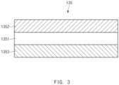
- FIG. 3 is a cross-sectional view of a pouch film 135 forming the battery case 13 according to an embodiment of the present invention.
- the battery case 13 is manufactured by performing drawing on the pouch film 135. That is, the pouch film 135 is elongated to form the cup part 133, thereby manufacturing the battery case 13. As illustrated in FIG. 3 , the pouch film 135 includes a gas barrier layer 1351, a surface protection layer 1352, and a sealant layer 1353.
- the gas barrier layer 1351 may secure mechanical strength of the battery case 13, block introduction and discharge of a gas or moisture outside the secondary battery 1, and prevent the electrolyte from leaking.
- the gas barrier layer 1351 includes a metal.
- aluminum (Al) foil is mainly used for the gas barrier layer 1351.
- Aluminum may secure the mechanical strength of a predetermined level or more, but be light in weight.
- aluminum may secure complement for electrochemical properties of the electrode assembly 10 and the electrolyte and heat dissipation.
- the present invention is not limited thereto.
- the gas barrier layer 1351 may be made of various materials.
- the gas barrier layer 1351 may be made of one material or a mixture of two or more materials selected from the group consisting of Fe, C, Cr, Mn, Ni and Al.
- the gas barrier layer 1351 is made of a material containing iron, the mechanical strength may be improved.
- the gas barrier layer 1351 is made of a material containing aluminum, flexibility may be improved.
- the material forming the gas barrier layer 1351 may be used in consideration of the characteristics of the gas barrier layer 1351.
- the surface protection layer 1352 is made of a polymer and disposed at the outermost layer to protect the secondary battery 1 against external friction and collision and also electrically insulates the electrode assembly 10 from the outside.
- the outermost layer represents a direction opposite to a direction in which the electrode assembly 10 is disposed with respect to the gas barrier layer 1351, i.e., in an outward direction.
- the surface protection layer 1352 may be made of at least one or more materials selected from the group consisting of polyethylene, polypropylene, polycarbonate, polyethylene terephthalate, polyvinyl chloride, acrylic polymer, polyacrylonitrile, polyimide, polyamide, cellulose, aramid, nylon, polyester, polyparaphenylene benzobisoxazole, polyarylate, teflon, and glass fiber. Particularly, a polymer such as a nylon resin or polyethylene terephthalate (PET) having mainly abrasion resistance and heat resistance is used. Also, the surface protection layer 1352 may have a single layer structure made of one material or a composite layer structure in which two or more materials are respectively formed as layers.
- the sealant layer 1353 is made of a polymer and disposed at the innermost layer to directly contact the electrode assembly 10.
- the pouch type battery case 13 may be manufactured while a portion thereof is elongated to form the cup part 133 having the accommodation space 1331 having a bag shape when the pouch film 135 having the stacked structure as described above is drawn by using a punch or the like. Also, when the electrode assembly 10 is accommodated in the accommodation space 1331, the electrolyte is injected. Thereafter, when the upper case 131 and the lower case 132 may contact each other, and thermal compression is applied to the sealing part 134, the sealant layers 1353 may be bonded to each other to seal the battery case 13.
- the sealant layer 1353 since the sealant layer 1353 directly contacts the electrode assembly 10, the sealant layer 1353 may have to have insulating properties. Also, since the sealant layer 1353 contacts the electrolyte, the sealant layer 1353 may have to have corrosion resistance. Also, since the inside of the battery case 13 is completely sealed to prevent materials from moving between the inside and outside of the battery case 13, high sealability has to be realized. That is, the sealing part 134 in which the sealant layers 1353 are bonded to each other should have superior bonding strength.
- the sealant layer 1353 may be made of at least one or more materials selected from the group consisting of polyethylene, polypropylene, polycarbonate, polyethylene terephthalate, polyvinyl chloride, acrylic polymer, polyacrylonitrile, polyimide, polyamide, cellulose, aramid, nylon, polyester, polyparaphenylene benzobisoxazole, polyarylate, teflon, and glass fiber.
- a polyolefin-based resin such as polypropylene (PP) or polyethylene (PE) may be used for the sealant layer 1353.
- Polypropylene (PP) is excellent in mechanical properties such as tensile strength, rigidity, surface hardness, abrasion resistance, and heat resistance and chemical properties such as corrosion resistance and thus is mainly used for manufacturing the sealant layer 1353.
- the sealant layer 1353 may be made of a cated polypropylene or a polypropylene-butylene-ethylene terpolymer.
- the sealant layer 1353 may have a single layer structure made of one material or a composite layer structure in which two or more materials are respectively formed as layers.
- FIG. 4 is a perspective view of the venting device 15 according to an embodiment of the present invention.
- the secondary battery 1 further includes at least one venting device 15.
- the bending of the plate spring 153 in the closed state of the venting device 15 may be minimized to reduce a deviation in opening pressure between the venting devices 15.
- the deviation between a numerical value of the opening pressure, which is designed before manufacturing the venting device 15, and an actual opening pressure may be reduced.
- the opening pressure means a specific pressure within the battery case 13 when the venting device 15 is opened.
- the venting device 15, which is inserted into a sealing part 134 of a pouch of the secondary battery 1, includes: a housing 151 inserted between both surfaces of the sealing part 134 so as to be sealed together with the sealing part 134; a sheet 152 which is formed in the housing 151 and through which a passage 154, through which the inside and outside of the pouch communicate with each other, passes; a plate spring 153 which opens and closes the passage 154 according to an internal pressure of the pouch and is made of made of a metal having elasticity; and a ball 155 disposed between the sheet 152 and the plate spring 153 so as to contact or be spaced apart from the sheet 152 at an outlet-side of the passage 154, thereby closing or opening the passage 154.
- the ball 155 may have a hemispherical shape to be attached to an inner surface of the plate spring 153.
- the housing 151 may be inserted between both the surfaces of the sealing part 134 so as to be sealed together with the sealing part 134.
- a sealant layer 1353 that is the innermost layer of the sealing part 134 contacts the housing 151.
- a sealant layer 1353 of the sealing part 134 is fused to be sealed together with the housing 151.
- the housing 151 may include an upper housing 1511 and a lower housing 1512, and a stepped portion may be formed between the upper housing 1511 and the lower housing 1512. The stepped portion may be formed because the upper housing 1511 and the lower housing 1512 have shapes or sizes different from each other.
- the upper housing 1511 may have a transverse cross-section having a circular cylinder shape
- the lower housing 1512 may have a transverse cross-section having an oval cylinder shape
- the lower housing 1512 may have a width less than that of the upper housing 1511.
- the lower housing 1512 may be inserted between both the surfaces of the sealing part 134 so as to be sealed together with the sealing part 134.
- the lower housing 1512 may be fused to the inner surface of the sealing part 134, and the upper housing 1511 may protrude to the outside of the pouch.
- the lower housing 1512 may have a width less than a thickness of the sealing part 134.
- a long axis of the transverse cross-section has a width that is 6 mm or more less.
- the lower housing 1512 may have an oval cylinder shape having an oval transverse cross-section.
- the upper housing 1511 may have a width less than a thickness of the sealing part 134.
- the transverse cross-section has a diameter 8 mm or more less.
- the present invention is not limited thereto.
- the upper housing 1511 and the lower housing 1512 may have various shapes, for example, one cylinder shape without being distinguished from each other.
- the sheet 152 may be formed in the housing 151. Also, the passage 154 through which the inside and the outside of the pouch communicate with each other may be formed to pass through a center of the sheet 152.
- the sheet 152 will be described below in detail.
- the plate spring 153 may be made of a metal to open and close the passage 154 formed in the sheet 152 according to an internal pressure of the pouch. Particularly, when the internal pressure of the pouch is less than a specific pressure, the plate spring 153 closes an outlet 1541 of the passage 154. Also, when the internal pressure of the pouch gradually increase to exceed the specific pressure, the plate spring 153 may be spaced apart from the sheet 152 to open the outlet 1541 of the passage 154.
- the passage 154 is opened and closed by using a coil spring.
- the venting device has to be miniaturized so as to be inserted into the sealing part 134 of the secondary battery 1.
- the venting device may be complicated in structure and limited in miniaturization.
- the plate spring 153 may be used to simplify the structure of the venting device 15 and miniaturize the venting device 15 so as to be inserted into the sealing part 134 of the secondary battery 1.
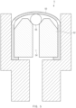
- FIG. 5 is a schematic view of the venting device 5 in which the ball 55 has a spherical shape.
- the ball 55 may be disposed between the plate spring 53 and the sheet 52 so as to contact or be spaced apart from the sheet 52, thereby closing or opening the passage 54.
- the plate spring 53 may be largely bent even though a state in which the ball 55 contacts the sheet 52 to close the passage 54 is a state in which external force relatively minimally acts to the plate spring 53. Therefore, when the plurality of venting devices 5 are manufactured, there is a problem that a deviation occurs in opening pressure between the plurality of venting devices 5 according to a degree of bending of the plate spring 53. Also, there is a problem that a deviation occurs between a numerical value of the opening pressure, which is designed before manufacturing the venting device 5, and a numerical value of an actual opening pressure after manufacturing the venting device 5.
- FIG. 6 is a schematic view of the sheet 152 according to an embodiment of the present invention.
- the sheet 152 is formed in the housing 151, and the passage 154 passes through the sheet 152.
- the sheet 152 may be made of a metal to improve durability, but may also be made of polymer to prevent a gap between components.
- the polymer may include a polyolefin-based polymer such as polypropylene (PP).
- PP polypropylene
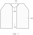
- FIG. 7 is a schematic view illustrating a state in which the ball 155 is seated on the sheet 152 according to an embodiment of the present invention.
- the ball 155 may have a hemispherical shape and be disposed at the outlet-side of the passage 154 formed in the sheet 152. Also, the ball 155 may be disposed between the plate spring 153 and the sheet 152 so as to contact or be spaced apart from the sheet 152, thereby closing or opening the passage 154.
- the ball 155 may be made of the polymer to more improve adhesion with respect to the sheet 152. However, the ball 155 may be made of a metal to improve durability.
- the ball 155 has a hemispherical shape and is attached to an inner surface of the plate spring 153.
- a plane rather than the hemispherical surface of the ball 155 is attached to the inner surface of the plate spring 153.
- the chamfered or filleted surface 1521 of the sheet 152 has a predetermined inclination. As illustrated in FIG. 7 , the hemispherical surface of the ball 155 may face one surface 1521 of the sheet 152 and may be easily seated.
- the ball 155 has a diameter less than the widest width of the one surface 1521 of the sheet 152 and larger than the narrowest width of the one surface 1521 of the sheet 152 so that the ball 155 is easily seated on the sheet 152. Then, when the ball 155 is seated, the plane of the ball 155 is formed at a height that is approximately similar to the highest point of the sheet 152. As a result, since the plate spring 153 is not largely bent even in a state in which the ball 155 closes the passage 154, the deviation in opening pressure between the venting devices 15 may be reduced, and also, the deviation between the numerical value of the opening pressure, which is designed before manufacturing the venting device 15, and the actual opening pressure may be reduced.
- the plane of the ball 155 may be slightly higher than the highest point of the sheet 152.
- elastic force of the plate spring 153 may be efficiently applied to the ball 155 to improve the adhesion of the sheet 152 of the ball 155.
- FIG. 8 is a schematic view of the plate spring 153 according to an embodiment of the present invention.
- the plate spring 153 may be manufactured by molding a metal plate.
- the metal plate has a wide and thin plate shape and is made of a metal.
- the metal plate may include aluminum (Al) or stainless steel (STS).
- STS stainless steel
- a drawing process of elongating the metal plate through a punch may be performed to manufacture the plate spring 153.
- the metal plate may be seated on a die, and a stripper may fix the metal plate. Then, the metal plate may be elongated through the punch to perform the drawing.
- the one side 1530 has a cap shape that is convex outward and provide an insertion space 1534 into which the sheet 152 is inserted.
- the one side 1530 of the plate spring 153 may mean a ceiling of the cap shape as illustrated in FIG. 8 .
- the present invention is not limited thereto.
- the one side 1530 of the plate spring 153 may include various portions.
- the plate spring 153 has elastic force to open and close the passage 154 formed in the sheet 152 together with the ball 155 according to the internal pressure of the pouch.
- a gas exhaust hole 1533 is punched in the one side 1530 of the plate spring 153.
- the one side 1530 of the plate spring 153 includes a central portion 1531 formed in a center thereof and a peripheral portion 1532 extending outward from the central portion 1531.
- the ball 155 is attached to a bottom surface of a central portion 1531 of the one side 1530 to close the passage 154 formed in the sheet 152, the gas exhaust hole 1533 is not punched in the central portion 1531.
- the gas exhaust hole 1533 is punched in the peripheral portion 1532 of the one side of the 1530 of the plate spring 153.
- An opening pressure of the venting device 15 may be changed according to the formed shape and area of the gas exhaust hole 1533.
- the gas exhaust hole 1533 may be adjusted in shape and area to adjust the opening pressure of the venting device 15.
- the opening pressure means a specific pressure within the pouch when the venting device 15 is opened.
- FIG. 9 is a schematic view illustrating a state in which the plate spring 153 surrounds the sheet 152 and the ball 155 according to an embodiment of the present invention.
- the plate spring 153 When the plate spring 153 is manufactured, as illustrated in FIG. 9 , the sheet 152 and the ball 155 are inserted into the insertion space 1534. As a result, the plate spring 153 surrounds the periphery of the sheet 152 and the ball 155. When the sheet 152 and the ball 155 are inserted into the insertion space 1534, it is preferable that the outlet-side of the passage 154 faces the one side 1530 of the plate spring 153. Thus, when the internal pressure of the pouch is less than a specific pressure, the one side 1530 of the plate spring 153 pushes the ball 155 inward from the outlet-side of the passage 154 formed in the sheet 152 to close the passage 154.
- the ball 155 is formed in a hemispherical shape, and the plane rather than the hemispherical surface of the ball 155 is attached to the inner surface of the plate spring 153.
- the adhesive is applied to the plane of the ball 155, and the sheet 152 and the ball 155 are inserted into the insertion space 1534, the plane of the ball 155 is attached to the inner surface of the central portion 1531 of the plate spring 153.
- the ball 155 and the sheet 152 may be inserted into the insertion space 1534 of the plate spring 153, but is not limited thereto.
- the sheet 152 may be inserted into the insertion space 1534.
- the gas exhaust hole 1533 may be formed in a peripheral portion 1532 of the one side 1530 of the plate spring 153.
- the passage 154 is opened so that the gas leaks to the outlet 1541 of the passage 154.
- the leaking gas has to be discharged to the outside through the gas exhaust hole 1533.
- the edge of the outer circumference of surface of the outlet-side of the passage 154 may be chamfered or filleted.
- the gas may be guided to the gas exhaust hole 1533.
- the one side 1530 of the plate spring 153 is pushed outward to provide a space to which the peripheral portion 1532 of the one side 1530 of the plate spring 153 moves inward.
- FIG. 10 is a schematic view illustrating a state in which an end 1535 of the other side of the plate spring 153 is bent toward the sheet 152 according to an embodiment of the present invention.
- the plate spring 153 is firmly fixed to the sheet 152.
- the one side 1530 of the plate spring 153 moves outward.
- the plate spring 153 is not entirely slid, but only one side 1530 of the plate spring 153 is deformed to move. If the plate spring 153 is slid, the plate spring 153 may be separated from the venting device 15. Particularly, only the central portion 1531 of the one side 1530 may be pushed outward, and the peripheral portion 1532 of the one side 1530 may move inward.
- the internal gas of the pouch may be discharged to the outside through the passage 154.
- the end 1535 of the other side of the plate spring 153 is bent toward the sheet 152 as illustrated in FIG. 10 .
- the detachment (separation) of the plate spring 153 from the sheet 152 may be prevented to fix the plate spring 153 to the venting device 15 without separating the plate spring 153 from the venting device 15.
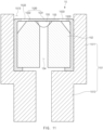
- FIG. 11 is a schematic view illustrating a configuration of the venting device 15 manufactured by inserting the plate spring 153 and the sheet 152 into the housing 151 according to an embodiment of the present invention.
- the plate spring 153 into which the sheet 152 is inserted is inserted into the housing 151 as illustrated in FIG. 11 .
- the venting device 15 according to an embodiment of the present invention may be completely manufactured.
- the venting device 15 manufactured as described above is inserted into the sealing part 134 of the pouch so as to be sealed together.
- the housing 151 includes the upper housing 1511 and the lower housing 1512
- the plate spring 153 and the sheet 152 are included in the upper housing 1511.
- the one side 1530 of the plate spring 153 faces an opening end of the upper housing 1511.
- the gas may be discharged to the outside through the gas exhaust hole 1533 formed in the one side 1530.
- the plate spring 153 is not slid as a whole, but only one side 1530 is deformed in the fixed state.
- a gap between the plate spring 153 and the housing 151 is minimized when the plate spring 153 is inserted into the housing 151 so that frictional force acts largely between an outer circumferential surface of the plate spring 153 and an inner circumferential surface of the housing 151.
- the present invention is not limited thereto. In order that the frictional force further increases, surface roughness of the outer circumferential surface of the plate spring 153 or the inner circumferential surface of the housing 151 may increase so that a frictional coefficient increases.
- the plate spring 153 may be fixed to the housing 151 through various methods, for example, a method in which a separate adhesive is applied between the plate spring 153 and the housing 151, or a protrusion protrudes from one of the plate spring 153 and the housing 151, and a groove is formed in the other of the plate spring 153 and the housing 151.
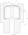
- FIG. 12 is an operation diagram illustrating an operation of the venting device 15 according to an embodiment of the present invention.
- the gas When the gas is generated in the pouch to gradually increase in internal pressure of the pouch and thus exceed a specific pressure, as illustrated in FIG. 12 , the gas pushes the ball 155 outward. As a result, since the ball 155 is pushed, the one side 1530 of the plate spring 153 is pushed outward. Also, the plate spring 153 may be spaced apart from the sheet 152 so that the ball 155 is separated from the sheet 152 to open the outlet 1541 of the passage 154. Therefore, the gas within the pouch may be discharged to the outside through the passage 154 and the gas exhaust hole 1533. Here, as described above, it is preferable that the plate spring 153 is not slid with respect to the sheet 152.
- the plate spring 153 is made of the metal and thus has the elasticity.
- the plate spring 153 returns to its original position by the elasticity of the plate spring 153.
- the ball 155 is pushed inward from the outlet-side of the passage 154 formed in the sheet 152 by the elastic force of the plate spring 153. As a result, the ball 155 is in close contact with the one surface 1521 of the sheet 152 to close the outlet 1541 of the passage 154.
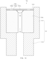
- FIG. 13 is a schematic view illustrating a venting device not according to the present invention.
- the plate spring 153 has the cap shape of which the one side 1530 is convex outward, and the sheet 152 and the ball 155 are inserted into the insertion space 1534 formed in the plate spring 153.
- the plate spring 153 since the plate spring 153 has the cap shape, it may not be easy to attach the plane of the ball 155 to the correct position of the inner surface of the plate spring 153.
- a plate spring 153a has a flat plate shape and contacts a sheet 152a.
- a separate fixing ring (not shown) may be inserted into an upper housing 1511 so as to be fixed to an upper portion of the plate spring 153a.
- the fixing ring has elasticity, and when being inserted into the upper housing 1511, external force may be applied to reduce a diameter, and then, after being inserted into the upper housing 1511, the external force may be removed to increase in diameter again.
- the elastic force acts as normal force on an inner circumferential surface of the upper housing 1511, friction force between the fixing ring and the inner circumferential surface of the upper housing 1511 may increase.
- the ball 155 may be easily attached to an accurate position of the inner surface of the central portion 1531a of the plate spring 153a, and the plate spring 153a may be easily fixed to the inside of the housing 1511 through the separate fixing ring.
- FIG. 14 is an operation diagram illustrating an operation of the venting device 15a according to another embodiment not part of the present invention.
- the venting device 15a when an internal pressure of a pouch exceeds a specific pressure, as illustrated in FIG. 14 , a gas pushes the ball 155 outward, and thus, as the ball is pushed, the plate spring 153a is also pushed outward. Also, the plate spring 153 may be spaced apart from a sheet 152a so that the ball 155 is separated from the sheet 152a to open an outlet 1541 of a passage 154. Thus, a gas within the pouch may be discharged to the outside through the passage 154 and a gas exhaust hole 1533.
- the internal pressure of the pouch decreases again, and thus, the pressure of the gas, which pushes the plate spring 153a outward, decreases.
- the plate spring 153a returns to its original position by the elastic force of the plate spring 153a.
- the ball 155 is pushed inward from a side of an outlet 1541 of the passage 154 formed in the sheet 152a by the elastic force of the plate spring 153a. As a result, the ball 155 is in close contact with one surface 1521 of the sheet 152a to close the outlet 1541 of the passage 154.
Description
- The present application claims the benefit of the priority of
Korean Patent Application No. 10-2019-0022033, filed on February 25, 2019 - The present invention relates to a venting device, and more particularly, to at least one venting device,which is inserted into a sealing part of a pouch of a secondary battery to discharge a gas within the pouch to the outside and minimize bending of a plate spring in a closed state.
- In general, secondary batteries include nickelcadmium batteries, nickel-hydrogen batteries, lithium ion batteries, and lithium ion polymer batteries. Such a secondary battery is being applied to and used in small-sized products such as digital cameras, P-DVDs, MP3Ps, mobile phones, PDAs, portable game devices, power tools, E-bikes, and the like as well as large-sized products requiring high power such as electric vehicles and hybrid vehicles, power storage devices for storing surplus power or renewable energy, and backup power storage devices.
- Such a secondary battery is classified into a pouch type secondary battery and a can type secondary battery according to a material of a case accommodating the electrode assembly. In the pouch type secondary battery, an electrode assembly is accommodated in a pouch made of a flexible polymer material. Also, in the can type secondary battery, an electrode assembly is accommodated in a case made of a metal or plastic material.
- The secondary battery may be deteriorated in safety due to various problems such as internal short circuit due to an external impact, heat generation due to overcharging and overdischarging, electrolyte decomposition due to the generated heat, and a thermal runaway phenomenon. Particularly, when a gas is generated due to decomposition of an electrolyte to increase in pressure within the secondary battery, a problem occurs that the secondary battery is exploded.
- Particularly, when the secondary battery is repeatedly charged and discharged, a gas is generated by electrochemical reaction between the electrolyte and an electrode active material. Here, the generated gas may allow the secondary battery to increase in internal pressure to cause problems such as weakening of bonding force between components, damage of a case of the secondary battery, an early operation of a protection circuit, deformation of an electrode, internal short circuit, explosion, and the like. Thus, in the case of the can type secondary battery, a protection member such as a CID filter and a safety vent is provided to physically interrupt an electrical connection when an internal pressure of a case increases. However, in the case of the pouch type secondary battery according to the related art, the protection member is not sufficiently provided.
-
WO2015/160134 relates to safety valve for energy storage apparatus comprising a body composed of a first structure having a jet hole formed at one side thereof, and a second structure having a hole formed at one side thereof and integrally combined with the first structure; and a pair of elastic bodies arranged inside the first structure and operating in response to pressure. In addition, the present invention comprises: a body composed of a first structure and a second structure; a lift body arranged inside the first structure and operating in response to pressure; and a guide member arranged on the lift body and guiding movement of the lift body. The present invention, as above, has an advantage of smoothly discharging gases generated from an energy storage apparatus while minimizing the volume of a safety valve by applying a simple structure such as a pair of elastic bodies or the lift body. -
JP2006313715 - An object of the present invention is to provide at least one venting device, which is inserted into a sealing part of a pouch of a secondary battery to discharge a gas within the pouch to the outside and minimize bending of a plate spring in a closed state.
- The objects of the present invention are not limited to the aforementioned object, but other objects not described herein will be clearly understood by those skilled in the art from descriptions below.
- The invention is defined in the pending set of claims. According to
claim 1, the invention is a venting device, which is inserted into a sealing part of a pouch of a secondary battery, according to the present invention for solving the above problem includes: a housing inserted between both surfaces of the sealing part so as to be sealed together with the sealing part; a sheet which is formed in the housing and through which a passage, through which the inside and outside of the pouch communicate with each other, passes; a plate spring which opens and closes the passage according to an internal pressure of the pouch and is made of made of a metal having elasticity; and a ball disposed between the sheet and the plate spring so as to contact or be spaced apart from the sheet at an outlet-side of the passage, thereby closing or opening the passage, wherein the ball has a hemispherical shape to be attached to an inner surface of the plate spring. - Also, the plate spring may include: a central portion formed at a center thereof; and a peripheral portion extending outward from the central portion, wherein the ball may be attached to the central portion, and a gas exhaust hole may be punched in the peripheral portion.
- Also, the plate spring has one side having a cap shape that is convex outward and provide an insertion space into which the sheet and the ball are inserted therein.
- Also, an end of the other side of the plate spring may be bent toward the sheet inserted into the insertion space.
- Also, the plate spring may have a flat plate shape and contact the sheet.
- Also, in the sheet, an edge of an inner circumference of a surface of the outlet-side of the passage may be chamfered or filleted.
- Also, in the sheet, an edge of an inner circumference of the surface of the outlet-side of the passage may be chamfered or filleted.
- Also, the housing may include an upper housing and a lower housing, which have shapes or sizes different from each other.
- Also, the lower housing may have a width less than that of the upper housing.
- Also, the upper housing may have a circular cylinder shape, and the lower housing may have an oval cylinder shape.
- Also, the present invention provides a pouch type secondary battery in which the venting device is inserted into a sealing part of a pouch, a battery module including the pouch type secondary battery as a unit cell, and a device including the battery module.
- The device may include a computer, a notebook, a smart phone, a mobile phone, a tablet PC, a wearable electronic device, a power tool, an electric vehicle (EV), a hybrid electric vehicle (HEV), a plug-in hybrid electric vehicle (PHEV), or a power storage device, but is not limited thereto.
- The structures of the battery module and the device and the method for manufacturing them are well known in the art, and thus their detailed descriptions will be omitted herein.
- Particularities of other embodiments are included in the detailed description and drawings.
- The embodiments of the present invention may have at least the following effects.
- The bending of the plate spring may be minimized in the state in which the venting devices are closed to reduce the deviation in opening pressure between the venting devices.
- Also, the deviation between the numerical value of the opening pressure, which is designed before manufacturing the venting device, and the actual opening pressure may be reduced.
- The effects of the prevent invention are not limited by the aforementioned description, and thus, more varied effects are involved in this specification.
-
-
FIG. 1 is an assembled view of a secondary battery including a venting device according to an embodiment of the present invention. -
FIG. 2 is a perspective view of the secondary battery ofFIG. 1 , which is completely manufactured. -
FIG. 3 is a cross-sectional view of a pouch film forming a battery case according to an embodiment of the present invention. -
FIG. 4 is a perspective view of a venting device according to an embodiment of the present invention. -
FIG. 5 is a schematic view of the venting device in which a ball has a spherical shape. -
FIG. 6 is a schematic view of a sheet according to an embodiment of the present invention. -
FIG. 7 is a schematic view illustrating a state in which the ball is seated on a sheet according to an embodiment of the present invention. -
FIG. 8 is a schematic view of a plate spring according to an embodiment of the present invention. -
FIG. 9 is a schematic view illustrating a state in which the plate spring surrounds the sheet and the ball according to an embodiment of the present invention. -
FIG. 10 is a schematic view illustrating a state in which an end of the other side of the plate spring is bent toward the sheet according to an embodiment of the present invention. -
FIG. 11 is a schematic view illustrating a configuration of the venting device manufactured by inserting the plate spring and the sheet into a housing according to an embodiment of the present invention. -
FIG. 12 is an operation diagram illustrating an operation of the venting device according to an embodiment of the present invention. -
FIG. 13 is a schematic view illustrating a venting device not according to the present invention. -
FIG. 14 is an operation diagram illustrating an operation of the venting device according to another embodiment, which is not part of the present invention. - Advantages and features of the present invention, and implementation methods thereof will be clarified through following embodiments described with reference to the accompanying drawings. The present invention may, however be embodied in different forms and should not be construed as limited to the embodiments set forth herein. Rather, these embodiments are provided so that this disclosure will be thorough and complete, and will fully convey the scope of the present invention to those skilled in the art. Further, the present invention is only defined by scopes of claims. Like reference numerals refer to like elements throughout.
- Unless terms used in the present invention are defined differently, all terms (including technical and scientific terms) used herein have the same meaning as generally understood by those skilled in the art. Also, unless defined clearly and apparently in the description, the terms as defined in a commonly used dictionary are not ideally or excessively construed as having formal meaning.
- In the following description, the technical terms are used only for explaining a specific exemplary embodiment while not limiting the present invention. In this specification, the terms of a singular form may comprise plural forms unless specifically mentioned. The meaning of "comprises" and/or "comprising" does not exclude other components besides a mentioned component.
- Hereinafter, preferred embodiments will be described in detail with reference to the accompanying drawings.
-
FIG. 1 is an assembled view of asecondary battery 1 including aventing device 15 according to an embodiment of the present invention, andFIG. 2 is a perspective view of thesecondary battery 1 ofFIG. 1 , which is completely manufactured. - In a process of manufacturing a pouch type
secondary battery 1, first, slurry in which an electrode active material, a binder, and a plasticizer are mixed with each other is applied to a positive electrode collector and a negative electrode collector to manufacture electrodes such as a positive electrode and a negative electrode. Thereafter, the negative electrode and the positive electrode are respectively stacked on both sides of a separator to form anelectrode assembly 10 having a predetermined shape, and then, theelectrode assembly 10 is inserted into abattery case 13, an electrolyte is injected, and sealing is performed. - Specifically, the
electrode assembly 10 includes two types of electrodes, such as the positive electrode and the negative electrode, and the separator interposed between the electrodes to insulate the electrodes from each other. Theelectrode assembly 10 may be a stack type, a jelly roll type, a stacked and folding type, or the like. Each of the two types of electrodes, i.e., the positive electrode and the negative electrode has a structure in which active material slurry is applied to the electrode collector having a metal foil or metal mesh shape. The slurry may be usually formed by agitating a granular active material, an auxiliary conductor, a binder, and a plasticizer with a solvent added. The solvent may be removed in the subsequent process. - As illustrated in
FIG. 1 , theelectrode assembly 10 includes anelectrode tab 11. Theelectrode tab 11 protrudes from each of the positive electrode and the negative electrode of theelectrode assembly 10 to provide a path, through which electrons move, between the inside and outside of theelectrode assembly 10. A collector of theelectrode assembly 10 is constituted by a portion coated with an electrode active material and a distal end, on which the electrode active material is not applied, i.e., a non-coating portion. Also, theelectrode tab 11 may be formed by cutting the non-coating portion or by connecting a separate conductive member to the non-coating portion through ultrasonic welding. As illustrated inFIG. 1 , theelectrode tabs 11 may protrude from one side of theelectrode assembly 10 in the same direction, but the present invention is not limited thereto. For example, theelectrode tabs 11 may protrude in directions different from each other. - In the
electrode assembly 10, theelectrode lead 12 is connected to theelectrode tab 11 through spot welding. Also, a portion of theelectrode lead 12 is surrounded by aninsulation part 14. Aninsulation part 14 may be disposed to be limited within a sealingpart 134, at which anupper case 131 and alower case 132 of thebattery case 13 are thermally fused, so as to be bonded to thebattery case 13. Also, electricity generated from theelectrode assembly 10 may be prevented from flowing to thebattery case 13 through theelectrode lead 12, and the sealing of thebattery case 13 may be maintained. Thus, theinsulation part 14 may be made of a nonconductor having non-conductivity, which is not electrically conductive. In general, although an insulation tape which is easily attached to theelectrode lead 12 and has a relatively thin thickness is mainly used as theinsulation part 14, the present invention is not limited thereto. For example, various members may be used as theinsulation part 14 as long as the members are capable of insulating theelectrode lead 12. - The
electrode lead 12 includes apositive electrode lead 121 having one end connected to apositive electrode tab 111 to extend in a direction in which thepositive electrode tab 111 protrudes and anegative electrode lead 122 having one end connected to anegative electrode tab 112 to extend in a direction in which thenegative electrode tab 112 protrudes. On the other hand, as illustrated inFIG 1 , all of the other ends of thepositive electrode lead 121 and thenegative electrode lead 122 protrude to the outside of thebattery case 13. As a result, electricity generated in theelectrode assembly 10 may be supplied to the outside. Also, since each of thepositive electrode tab 111 and thenegative electrode tab 112 is formed to protrude in various directions, each of thepositive electrode lead 121 and thenegative electrode lead 122 may extend in various directions. - The
positive electrode lead 121 and thenegative electrode lead 122 may be made of materials different from each other. That is, thepositive electrode lead 121 may be made of the same material as the positive current collector, i.e., an aluminum (Al) material, and thenegative electrode lead 122 may be made of the same material as the negative current collector, i.e., a copper (Cu) material or a copper material coated with nickel (Ni). Also, a portion of theelectrode lead 12, which protrudes to the outside of thebattery case 13, may be provided as a terminal part and electrically connected to an external terminal. - The
battery case 13 is a pouch made of a flexible material. Hereinafter, the case in which thebattery case 13 is the pouch will be described. Thebattery case 13 accommodates theelectrode assembly 10 so that a portion of theelectrode lead 12, i.e., the terminal part is exposed and then is sealed. As illustrated inFIG. 1 , thebattery case 13 includes theupper case 131 and thelower case 132. Acup part 133 having anaccommodation space 1331 accommodating theelectrode assembly 10 is formed in thelower case 132, andupper case 131 may cover an upper side of theaccommodation space 1331 so that theelectrode assembly 10 is not separated to the outside of thebattery case 13. Here, as illustrated inFIG. 1 , thecup part 133 having theaccommodation space 1331 may be formed in theupper case 131 to accommodate theelectrode assembly 10 in the upper portion. As illustrated inFIG. 1 , one side of theupper case 131 and one side of thelower case 132 may be connected to each other. However, the present invention is not limited thereto. For example, theupper case 131 and thelower case 132 may be separately manufactured to be separated from each other. - After the
upper case 131 and thelower case 132 of thebattery case 13 contact each other, the sealingpart 134 formed on an edge may be sealed. Here, as illustrated inFIG. 1 , according to an embodiment of the present invention, the ventingdevice 15 is inserted between both surfaces of the sealingpart 134 so as to be sealed together with the sealingpart 134 and thus be fixed within the sealingpart 134. Also, the ventingdevice 15 includes a passage through which the inside and the outside of thebattery case 13 communicate with each other. When an internal pressure of thebattery case 13 increases, an internal gas is discharged to the outside to adjust the pressure. The ventingdevice 15 will be described below in detail. - When an
electrode lead 12 is connected to theelectrode tab 11 of theelectrode assembly 10, and theinsulation part 14 is provided on a portion of theelectrode lead 12, theelectrode assembly 10 may be accommodated in theaccommodation space 1331 provided in thecup part 133 of thelower case 132, and theupper case 131 may cover an upper portion of theaccommodation space 1331. Also, the electrolyte is injected, and the sealing part provided on an edge of each of theupper case 131 and thelower case 132 is sealed. The electrolyte may move lithium ions generated by electrochemical reaction of the electrode during charging and discharging of thesecondary battery 1. The electrolyte may include a non-aqueous organic electrolyte that is a mixture of a lithium salt and a high-purity organic solvent or a polymer using a polymer electrolyte. As illustrated inFIG. 2 , the pouch typesecondary battery 1 may be manufactured through the above-described method. -
FIG. 3 is a cross-sectional view of apouch film 135 forming thebattery case 13 according to an embodiment of the present invention. - The
battery case 13 is manufactured by performing drawing on thepouch film 135. That is, thepouch film 135 is elongated to form thecup part 133, thereby manufacturing thebattery case 13. As illustrated inFIG. 3 , thepouch film 135 includes agas barrier layer 1351, asurface protection layer 1352, and asealant layer 1353. - The
gas barrier layer 1351 may secure mechanical strength of thebattery case 13, block introduction and discharge of a gas or moisture outside thesecondary battery 1, and prevent the electrolyte from leaking. In general, thegas barrier layer 1351 includes a metal. Particularly, aluminum (Al) foil is mainly used for thegas barrier layer 1351. Aluminum may secure the mechanical strength of a predetermined level or more, but be light in weight. Thus, aluminum may secure complement for electrochemical properties of theelectrode assembly 10 and the electrolyte and heat dissipation. However, the present invention is not limited thereto. For example, thegas barrier layer 1351 may be made of various materials. For example, thegas barrier layer 1351 may be made of one material or a mixture of two or more materials selected from the group consisting of Fe, C, Cr, Mn, Ni and Al. Here, when thegas barrier layer 1351 is made of a material containing iron, the mechanical strength may be improved. When thegas barrier layer 1351 is made of a material containing aluminum, flexibility may be improved. Thus, the material forming thegas barrier layer 1351 may be used in consideration of the characteristics of thegas barrier layer 1351. - The
surface protection layer 1352 is made of a polymer and disposed at the outermost layer to protect thesecondary battery 1 against external friction and collision and also electrically insulates theelectrode assembly 10 from the outside. Here, the outermost layer represents a direction opposite to a direction in which theelectrode assembly 10 is disposed with respect to thegas barrier layer 1351, i.e., in an outward direction. Thesurface protection layer 1352 may be made of at least one or more materials selected from the group consisting of polyethylene, polypropylene, polycarbonate, polyethylene terephthalate, polyvinyl chloride, acrylic polymer, polyacrylonitrile, polyimide, polyamide, cellulose, aramid, nylon, polyester, polyparaphenylene benzobisoxazole, polyarylate, teflon, and glass fiber. Particularly, a polymer such as a nylon resin or polyethylene terephthalate (PET) having mainly abrasion resistance and heat resistance is used. Also, thesurface protection layer 1352 may have a single layer structure made of one material or a composite layer structure in which two or more materials are respectively formed as layers. - The
sealant layer 1353 is made of a polymer and disposed at the innermost layer to directly contact theelectrode assembly 10. The pouchtype battery case 13 may be manufactured while a portion thereof is elongated to form thecup part 133 having theaccommodation space 1331 having a bag shape when thepouch film 135 having the stacked structure as described above is drawn by using a punch or the like. Also, when theelectrode assembly 10 is accommodated in theaccommodation space 1331, the electrolyte is injected. Thereafter, when theupper case 131 and thelower case 132 may contact each other, and thermal compression is applied to the sealingpart 134, thesealant layers 1353 may be bonded to each other to seal thebattery case 13. Here, since thesealant layer 1353 directly contacts theelectrode assembly 10, thesealant layer 1353 may have to have insulating properties. Also, since thesealant layer 1353 contacts the electrolyte, thesealant layer 1353 may have to have corrosion resistance. Also, since the inside of thebattery case 13 is completely sealed to prevent materials from moving between the inside and outside of thebattery case 13, high sealability has to be realized. That is, the sealingpart 134 in which thesealant layers 1353 are bonded to each other should have superior bonding strength. In general, thesealant layer 1353 may be made of at least one or more materials selected from the group consisting of polyethylene, polypropylene, polycarbonate, polyethylene terephthalate, polyvinyl chloride, acrylic polymer, polyacrylonitrile, polyimide, polyamide, cellulose, aramid, nylon, polyester, polyparaphenylene benzobisoxazole, polyarylate, teflon, and glass fiber. Particularly, a polyolefin-based resin such as polypropylene (PP) or polyethylene (PE) may be used for thesealant layer 1353. Polypropylene (PP) is excellent in mechanical properties such as tensile strength, rigidity, surface hardness, abrasion resistance, and heat resistance and chemical properties such as corrosion resistance and thus is mainly used for manufacturing thesealant layer 1353. Furthermore, thesealant layer 1353 may be made of a cated polypropylene or a polypropylene-butylene-ethylene terpolymer. Also, thesealant layer 1353 may have a single layer structure made of one material or a composite layer structure in which two or more materials are respectively formed as layers. -
FIG. 4 is a perspective view of theventing device 15 according to an embodiment of the present invention. - The
secondary battery 1 according to an embodiment of the present invention further includes at least oneventing device 15. According to an embodiment of the present invention, the bending of theplate spring 153 in the closed state of theventing device 15 may be minimized to reduce a deviation in opening pressure between the ventingdevices 15. Also, the deviation between a numerical value of the opening pressure, which is designed before manufacturing theventing device 15, and an actual opening pressure may be reduced. Here, the opening pressure means a specific pressure within thebattery case 13 when theventing device 15 is opened. - For this, the venting
device 15, which is inserted into a sealingpart 134 of a pouch of thesecondary battery 1, according to an embodiment of the present invention includes: ahousing 151 inserted between both surfaces of the sealingpart 134 so as to be sealed together with the sealingpart 134; asheet 152 which is formed in thehousing 151 and through which apassage 154, through which the inside and outside of the pouch communicate with each other, passes; aplate spring 153 which opens and closes thepassage 154 according to an internal pressure of the pouch and is made of made of a metal having elasticity; and aball 155 disposed between thesheet 152 and theplate spring 153 so as to contact or be spaced apart from thesheet 152 at an outlet-side of thepassage 154, thereby closing or opening thepassage 154. Theball 155 may have a hemispherical shape to be attached to an inner surface of theplate spring 153. - The
housing 151 may be inserted between both the surfaces of the sealingpart 134 so as to be sealed together with the sealingpart 134. When thehousing 151 is inserted between both the surfaces of the sealingpart 134, asealant layer 1353 that is the innermost layer of the sealingpart 134 contacts thehousing 151. Also, when heat and a pressure are applied, asealant layer 1353 of the sealingpart 134 is fused to be sealed together with thehousing 151. As illustrated inFIG. 4 , thehousing 151 may include anupper housing 1511 and alower housing 1512, and a stepped portion may be formed between theupper housing 1511 and thelower housing 1512. The stepped portion may be formed because theupper housing 1511 and thelower housing 1512 have shapes or sizes different from each other. For example, theupper housing 1511 may have a transverse cross-section having a circular cylinder shape, and thelower housing 1512 may have a transverse cross-section having an oval cylinder shape. Alternatively, thelower housing 1512 may have a width less than that of theupper housing 1511. Thus, thelower housing 1512 may be inserted between both the surfaces of the sealingpart 134 so as to be sealed together with the sealingpart 134. Thus, thelower housing 1512 may be fused to the inner surface of the sealingpart 134, and theupper housing 1511 may protrude to the outside of the pouch. - Here, if the
lower housing 1512 has an excessively large width, the sealingpart 134 has to be deformed in size. Thus, the sealing of the sealingpart 134 may be damaged. Thus, thelower housing 1512 may have a width less than a thickness of the sealingpart 134. Particularly, it is preferable that a long axis of the transverse cross-section has a width that is 6 mm or more less. Also, as described above, thelower housing 1512 may have an oval cylinder shape having an oval transverse cross-section. Thus, thelower housing 1512 may be easily sealed to the sealingpart 134, and the sealing may be maintained for a long time without being broken. - Also, if the
upper housing 1511 has an excessively large size, theupper housing 1511 protruding to the outside of the pouch may interfere with othersecondary batteries 1 that are disposed in the vicinity of theupper housing 1511. Thus, it may be difficult to assemble a package or module of thesecondary battery 1. Thus, theupper housing 1511 may have a width less than a thickness of the sealingpart 134. Particularly, it is preferable that the transverse cross-section has a diameter 8 mm or more less. However, the present invention is not limited thereto. For example, theupper housing 1511 and thelower housing 1512 may have various shapes, for example, one cylinder shape without being distinguished from each other. - The
sheet 152 may be formed in thehousing 151. Also, thepassage 154 through which the inside and the outside of the pouch communicate with each other may be formed to pass through a center of thesheet 152. Thesheet 152 will be described below in detail. - The
plate spring 153 may be made of a metal to open and close thepassage 154 formed in thesheet 152 according to an internal pressure of the pouch. Particularly, when the internal pressure of the pouch is less than a specific pressure, theplate spring 153 closes anoutlet 1541 of thepassage 154. Also, when the internal pressure of the pouch gradually increase to exceed the specific pressure, theplate spring 153 may be spaced apart from thesheet 152 to open theoutlet 1541 of thepassage 154. - According to the related art, the
passage 154 is opened and closed by using a coil spring. However, the venting device has to be miniaturized so as to be inserted into the sealingpart 134 of thesecondary battery 1. However, if the coil spring is used like the related art, the venting device may be complicated in structure and limited in miniaturization. Thus, according to an embodiment of the present invention, theplate spring 153 may be used to simplify the structure of theventing device 15 and miniaturize theventing device 15 so as to be inserted into the sealingpart 134 of thesecondary battery 1. -
FIG. 5 is a schematic view of theventing device 5 in which theball 55 has a spherical shape. - The
ball 55 may be disposed between theplate spring 53 and thesheet 52 so as to contact or be spaced apart from thesheet 52, thereby closing or opening thepassage 54. However, when theball 55 has the spherical shape as illustrated inFIG. 5 , theplate spring 53 may be largely bent even though a state in which theball 55 contacts thesheet 52 to close thepassage 54 is a state in which external force relatively minimally acts to theplate spring 53. Therefore, when the plurality of ventingdevices 5 are manufactured, there is a problem that a deviation occurs in opening pressure between the plurality of ventingdevices 5 according to a degree of bending of theplate spring 53. Also, there is a problem that a deviation occurs between a numerical value of the opening pressure, which is designed before manufacturing theventing device 5, and a numerical value of an actual opening pressure after manufacturing theventing device 5. - Furthermore, since the bent state of the
plate spring 53 is maintained for a long time, a creep phenomenon occurs in theplate spring 53 to reduce the lifespan of theplate spring 53 and also reduce the lifespan of thewhole venting devices 5. -
FIG. 6 is a schematic view of thesheet 152 according to an embodiment of the present invention. - The
sheet 152 is formed in thehousing 151, and thepassage 154 passes through thesheet 152. Thesheet 152 may be made of a metal to improve durability, but may also be made of polymer to prevent a gap between components. In particular, the polymer may include a polyolefin-based polymer such as polypropylene (PP). As illustrated inFIG. 6 , in thesheet 152, an edge of an inner circumference of a surface of the outlet-side of thepassage 154 is chamfered or filleted. -
FIG. 7 is a schematic view illustrating a state in which theball 155 is seated on thesheet 152 according to an embodiment of the present invention. - According to an embodiment of the present invention, the
ball 155 may have a hemispherical shape and be disposed at the outlet-side of thepassage 154 formed in thesheet 152. Also, theball 155 may be disposed between theplate spring 153 and thesheet 152 so as to contact or be spaced apart from thesheet 152, thereby closing or opening thepassage 154. Theball 155 may be made of the polymer to more improve adhesion with respect to thesheet 152. However, theball 155 may be made of a metal to improve durability. - The
ball 155 has a hemispherical shape and is attached to an inner surface of theplate spring 153. Here, in order to be more easily attached to theplate spring 153, a plane rather than the hemispherical surface of theball 155 is attached to the inner surface of theplate spring 153. The chamfered or filletedsurface 1521 of thesheet 152 has a predetermined inclination. As illustrated inFIG. 7 , the hemispherical surface of theball 155 may face onesurface 1521 of thesheet 152 and may be easily seated. - The
ball 155 has a diameter less than the widest width of the onesurface 1521 of thesheet 152 and larger than the narrowest width of the onesurface 1521 of thesheet 152 so that theball 155 is easily seated on thesheet 152. Then, when theball 155 is seated, the plane of theball 155 is formed at a height that is approximately similar to the highest point of thesheet 152. As a result, since theplate spring 153 is not largely bent even in a state in which theball 155 closes thepassage 154, the deviation in opening pressure between the ventingdevices 15 may be reduced, and also, the deviation between the numerical value of the opening pressure, which is designed before manufacturing theventing device 15, and the actual opening pressure may be reduced. More preferably, the plane of theball 155 may be slightly higher than the highest point of thesheet 152. As a result, elastic force of theplate spring 153 may be efficiently applied to theball 155 to improve the adhesion of thesheet 152 of theball 155. -
FIG. 8 is a schematic view of theplate spring 153 according to an embodiment of the present invention. - The
plate spring 153 may be manufactured by molding a metal plate. The metal plate has a wide and thin plate shape and is made of a metal. Particularly, the metal plate may include aluminum (Al) or stainless steel (STS). Also, a drawing process of elongating the metal plate through a punch may be performed to manufacture theplate spring 153. Particularly, the metal plate may be seated on a die, and a stripper may fix the metal plate. Then, the metal plate may be elongated through the punch to perform the drawing. As illustrated inFIG. 8 , in theplate spring 153 manufactured as described above, the oneside 1530 has a cap shape that is convex outward and provide aninsertion space 1534 into which thesheet 152 is inserted. The oneside 1530 of theplate spring 153 may mean a ceiling of the cap shape as illustrated inFIG. 8 . However, the present invention is not limited thereto. For example, the oneside 1530 of theplate spring 153 may include various portions. - The
plate spring 153 has elastic force to open and close thepassage 154 formed in thesheet 152 together with theball 155 according to the internal pressure of the pouch. For this, it is preferable that agas exhaust hole 1533 is punched in the oneside 1530 of theplate spring 153. Here, the oneside 1530 of theplate spring 153 includes acentral portion 1531 formed in a center thereof and aperipheral portion 1532 extending outward from thecentral portion 1531. Also, since theball 155 is attached to a bottom surface of acentral portion 1531 of the oneside 1530 to close thepassage 154 formed in thesheet 152, thegas exhaust hole 1533 is not punched in thecentral portion 1531. Thus, it is preferable that thegas exhaust hole 1533 is punched in theperipheral portion 1532 of the one side of the 1530 of theplate spring 153. - An opening pressure of the
venting device 15 may be changed according to the formed shape and area of thegas exhaust hole 1533. Thus, thegas exhaust hole 1533 may be adjusted in shape and area to adjust the opening pressure of theventing device 15. Here, the opening pressure means a specific pressure within the pouch when theventing device 15 is opened. -
FIG. 9 is a schematic view illustrating a state in which theplate spring 153 surrounds thesheet 152 and theball 155 according to an embodiment of the present invention. - When the
plate spring 153 is manufactured, as illustrated inFIG. 9 , thesheet 152 and theball 155 are inserted into theinsertion space 1534. As a result, theplate spring 153 surrounds the periphery of thesheet 152 and theball 155. When thesheet 152 and theball 155 are inserted into theinsertion space 1534, it is preferable that the outlet-side of thepassage 154 faces the oneside 1530 of theplate spring 153. Thus, when the internal pressure of the pouch is less than a specific pressure, the oneside 1530 of theplate spring 153 pushes theball 155 inward from the outlet-side of thepassage 154 formed in thesheet 152 to close thepassage 154. - The
ball 155 is formed in a hemispherical shape, and the plane rather than the hemispherical surface of theball 155 is attached to the inner surface of theplate spring 153. Here, when the adhesive is applied to the plane of theball 155, and thesheet 152 and theball 155 are inserted into theinsertion space 1534, the plane of theball 155 is attached to the inner surface of thecentral portion 1531 of theplate spring 153. Here, after theball 155 is seated first on thesheet 152, theball 155 and thesheet 152 may be inserted into theinsertion space 1534 of theplate spring 153, but is not limited thereto. For example, after theball 155 is attached to theplate spring 153, thesheet 152 may be inserted into theinsertion space 1534. - As described above, the
gas exhaust hole 1533 may be formed in aperipheral portion 1532 of the oneside 1530 of theplate spring 153. Thus, when the internal gas of the pouch pushes the oneside 1530 of theplate spring 153 outward, thepassage 154 is opened so that the gas leaks to theoutlet 1541 of thepassage 154. Here, the leaking gas has to be discharged to the outside through thegas exhaust hole 1533. Thus, in thesheet 152, the edge of the outer circumference of surface of the outlet-side of thepassage 154 may be chamfered or filleted. As a result, the gas may be guided to thegas exhaust hole 1533. Also, the oneside 1530 of theplate spring 153 is pushed outward to provide a space to which theperipheral portion 1532 of the oneside 1530 of theplate spring 153 moves inward. -
FIG. 10 is a schematic view illustrating a state in which anend 1535 of the other side of theplate spring 153 is bent toward thesheet 152 according to an embodiment of the present invention. - It is preferable that the
plate spring 153 is firmly fixed to thesheet 152. Thus, when the internal gas of the pouch pushes the oneside 1530 of theplate spring 153 outward through theball 155, the oneside 1530 of theplate spring 153 moves outward. Here, theplate spring 153 is not entirely slid, but only oneside 1530 of theplate spring 153 is deformed to move. If theplate spring 153 is slid, theplate spring 153 may be separated from the ventingdevice 15. Particularly, only thecentral portion 1531 of the oneside 1530 may be pushed outward, and theperipheral portion 1532 of the oneside 1530 may move inward. Thus, the internal gas of the pouch may be discharged to the outside through thepassage 154. - According to an embodiment of the present invention, after the
sheet 152 and theball 155 are inserted into theinsertion space 1534, theend 1535 of the other side of theplate spring 153 is bent toward thesheet 152 as illustrated inFIG. 10 . As a result, even though the internal gas of the pouch pushes the oneside 1530 of theplate spring 153 outward, the detachment (separation) of theplate spring 153 from thesheet 152 may be prevented to fix theplate spring 153 to theventing device 15 without separating theplate spring 153 from the ventingdevice 15. -
FIG. 11 is a schematic view illustrating a configuration of theventing device 15 manufactured by inserting theplate spring 153 and thesheet 152 into thehousing 151 according to an embodiment of the present invention. - The
plate spring 153 into which thesheet 152 is inserted is inserted into thehousing 151 as illustrated inFIG. 11 . As a result, the ventingdevice 15 according to an embodiment of the present invention may be completely manufactured. The ventingdevice 15 manufactured as described above is inserted into the sealingpart 134 of the pouch so as to be sealed together. - Here, if the
housing 151 includes theupper housing 1511 and thelower housing 1512, it is preferable that theplate spring 153 and thesheet 152 are included in theupper housing 1511. Also, as illustrated inFIG. 11 , it is preferable that the oneside 1530 of theplate spring 153 faces an opening end of theupper housing 1511. Thus, the gas may be discharged to the outside through thegas exhaust hole 1533 formed in the oneside 1530. - Also, as described above, the
plate spring 153 is not slid as a whole, but only oneside 1530 is deformed in the fixed state. Thus, it is preferable that a gap between theplate spring 153 and thehousing 151 is minimized when theplate spring 153 is inserted into thehousing 151 so that frictional force acts largely between an outer circumferential surface of theplate spring 153 and an inner circumferential surface of thehousing 151. However, the present invention is not limited thereto. In order that the frictional force further increases, surface roughness of the outer circumferential surface of theplate spring 153 or the inner circumferential surface of thehousing 151 may increase so that a frictional coefficient increases. Furthermore, theplate spring 153 may be fixed to thehousing 151 through various methods, for example, a method in which a separate adhesive is applied between theplate spring 153 and thehousing 151, or a protrusion protrudes from one of theplate spring 153 and thehousing 151, and a groove is formed in the other of theplate spring 153 and thehousing 151. -
FIG. 12 is an operation diagram illustrating an operation of theventing device 15 according to an embodiment of the present invention. - In addition, when the
secondary battery 1 is stored at a high temperature, an electrochemical reaction between the electrolyte and the electrode active material is quickly accelerated by the high temperature to generate a gas. - When the gas is generated in the pouch to gradually increase in internal pressure of the pouch and thus exceed a specific pressure, as illustrated in
FIG. 12 , the gas pushes theball 155 outward. As a result, since theball 155 is pushed, the oneside 1530 of theplate spring 153 is pushed outward. Also, theplate spring 153 may be spaced apart from thesheet 152 so that theball 155 is separated from thesheet 152 to open theoutlet 1541 of thepassage 154. Therefore, the gas within the pouch may be discharged to the outside through thepassage 154 and thegas exhaust hole 1533. Here, as described above, it is preferable that theplate spring 153 is not slid with respect to thesheet 152. - When the gas within the pouch is sufficiently discharged to the outside, the internal pressure of the pouch decreases again, and thus, the pressure of the gas pushing the
plate spring 153 outward decreases. However, theplate spring 153 is made of the metal and thus has the elasticity. Thus, when the internal pressure of the pouch is less than a specific pressure, theplate spring 153 returns to its original position by the elasticity of theplate spring 153. Also, theball 155 is pushed inward from the outlet-side of thepassage 154 formed in thesheet 152 by the elastic force of theplate spring 153. As a result, theball 155 is in close contact with the onesurface 1521 of thesheet 152 to close theoutlet 1541 of thepassage 154. -
FIG. 13 is a schematic view illustrating a venting device not according to the present invention. - According to the invention, the
plate spring 153 has the cap shape of which the oneside 1530 is convex outward, and thesheet 152 and theball 155 are inserted into theinsertion space 1534 formed in theplate spring 153. However, since theplate spring 153 has the cap shape, it may not be easy to attach the plane of theball 155 to the correct position of the inner surface of theplate spring 153. - Accordingly, in the
venting device 15a according to another embodiment, not part of the present invention, as illustrated inFIG. 13 , aplate spring 153a has a flat plate shape and contacts asheet 152a. Also, a separate fixing ring (not shown) may be inserted into anupper housing 1511 so as to be fixed to an upper portion of theplate spring 153a. The fixing ring has elasticity, and when being inserted into theupper housing 1511, external force may be applied to reduce a diameter, and then, after being inserted into theupper housing 1511, the external force may be removed to increase in diameter again. Thus, when the elastic force acts as normal force on an inner circumferential surface of theupper housing 1511, friction force between the fixing ring and the inner circumferential surface of theupper housing 1511 may increase. - Therefore, according to another embodiment, not part of the present invention, the
ball 155 may be easily attached to an accurate position of the inner surface of thecentral portion 1531a of theplate spring 153a, and theplate spring 153a may be easily fixed to the inside of thehousing 1511 through the separate fixing ring. -
FIG. 14 is an operation diagram illustrating an operation of theventing device 15a according to another embodiment not part of the present invention. - In the
venting device 15a according to another embodiment not part of the present invention, when an internal pressure of a pouch exceeds a specific pressure, as illustrated inFIG. 14 , a gas pushes theball 155 outward, and thus, as the ball is pushed, theplate spring 153a is also pushed outward. Also, theplate spring 153 may be spaced apart from asheet 152a so that theball 155 is separated from thesheet 152a to open anoutlet 1541 of apassage 154. Thus, a gas within the pouch may be discharged to the outside through thepassage 154 and agas exhaust hole 1533. - When the gas within the pouch is sufficiently discharged to the outside, the internal pressure of the pouch decreases again, and thus, the pressure of the gas, which pushes the
plate spring 153a outward, decreases. Thus, when the internal pressure of the pouch is less than the specific pressure, theplate spring 153a returns to its original position by the elastic force of theplate spring 153a. Also, theball 155 is pushed inward from a side of anoutlet 1541 of thepassage 154 formed in thesheet 152a by the elastic force of theplate spring 153a. As a result, theball 155 is in close contact with onesurface 1521 of thesheet 152a to close theoutlet 1541 of thepassage 154.
Claims (12)
- A venting device (15), which is inserted into a sealing part (134) of a pouch of a secondary battery, the venting device (15) comprising:a housing (151) inserted between both surfaces of the sealing part (134) so as to be sealed together with the sealing part (134);a sheet (152) which is formed in the housing (151) and through which a passage (154), through which the inside and outside of the pouch communicate with each other, passes;a plate spring (153) which opens and closes the passage (154) according to an internal pressure of the pouch and is made of a metal having elasticity; anda ball (155) disposed between the sheet (152) and the plate spring (153) so as to contact or be spaced apart from the sheet (152) at an outlet-side of the passage (154), thereby closing or opening the passage (154),wherein the ball (155) has a hemispherical shape to be attached to an inner surface of the plate spring (153),characterized in that the plate spring (153) has one side having a cap shape that is convex (1530) outward and provides an insertion space (1534) into which the sheet (152) and the ball (155) are inserted therein.
- The venting device of claim 1, wherein the plate spring (153) comprises:a central portion (1531) formed at a center thereof; anda peripheral portion (1532) extending outward from the central portion,wherein the ball (155) is attached to the central portion (1531), anda gas exhaust hole (1533) is punched in the peripheral portion (1532).
- The venting device of claim 2, wherein an end of the other side of the plate spring (153) is bent toward the sheet (152) inserted into the insertion space.
- The venting device of claim 1, wherein, in the sheet (152), an edge of an inner circumference of a surface of the outlet-side of the passage (154) is chamfered or filleted.
- The venting device of claim 1, wherein, in the sheet (152), an edge of an outer circumference of a surface of the outlet-side of the passage (154) is chamfered or filleted.
- The venting device of claim 1, wherein the housing (151) comprises an upper housing (1511) and a lower housing (1512), which have shapes or sizes different from each other.
- The venting device of claim 6, wherein the lower housing (1512) has a width less than that of the upper housing.
- The venting device of claim 6, wherein the upper housing (1511) has a circular cylinder shape, and
the lower housing (1512) has an oval cylinder shape. - A pouch type secondary battery in which the venting device of claim 1 is inserted into a sealing part of a pouch.
- A battery module comprising the pouch type secondary battery of claim 9 as a unit cell.
- A device comprising the battery module of claim 10.
- The device of claim 11, wherein the device comprises a computer, a notebook, a smart phone, a mobile phone, a tablet PC, a wearable electronic device, a power tool, an electric vehicle (EV), a hybrid electric vehicle (HEV), a plug-in hybrid electric vehicle (PHEV), or a power storage device.
Priority Applications (1)
| Application Number | Priority Date | Filing Date | Title |
|---|---|---|---|
| EP24158655.1A EP4350848A2 (en) | 2019-02-25 | 2019-12-06 | Venting device |
Applications Claiming Priority (2)
| Application Number | Priority Date | Filing Date | Title |
|---|---|---|---|
| KR1020190022033A KR102389409B1 (en) | 2019-02-25 | 2019-02-25 | The Apparatus For Venting |
| PCT/KR2019/017195 WO2020175773A1 (en) | 2019-02-25 | 2019-12-06 | Venting device |
Related Child Applications (2)
| Application Number | Title | Priority Date | Filing Date |
|---|---|---|---|
| EP24158655.1A Division-Into EP4350848A2 (en) | 2019-02-25 | 2019-12-06 | Venting device |
| EP24158655.1A Division EP4350848A2 (en) | 2019-02-25 | 2019-12-06 | Venting device |
Publications (3)
| Publication Number | Publication Date |
|---|---|
| EP3754750A1 EP3754750A1 (en) | 2020-12-23 |
| EP3754750A4 EP3754750A4 (en) | 2021-07-14 |
| EP3754750B1 true EP3754750B1 (en) | 2024-04-03 |
Family
ID=72239979
Family Applications (2)
| Application Number | Title | Priority Date | Filing Date |
|---|---|---|---|
| EP19916644.8A Active EP3754750B1 (en) | 2019-02-25 | 2019-12-06 | Venting device |
| EP24158655.1A Pending EP4350848A2 (en) | 2019-02-25 | 2019-12-06 | Venting device |
Family Applications After (1)
| Application Number | Title | Priority Date | Filing Date |
|---|---|---|---|
| EP24158655.1A Pending EP4350848A2 (en) | 2019-02-25 | 2019-12-06 | Venting device |
Country Status (6)
| Country | Link |
|---|---|
| US (1) | US11581600B2 (en) |
| EP (2) | EP3754750B1 (en) |
| JP (2) | JP7062197B2 (en) |
| KR (1) | KR102389409B1 (en) |
| CN (1) | CN111868962B (en) |
| WO (1) | WO2020175773A1 (en) |
Families Citing this family (4)
| Publication number | Priority date | Publication date | Assignee | Title |
|---|---|---|---|---|
| KR20220041746A (en) * | 2020-09-25 | 2022-04-01 | 주식회사 엘지에너지솔루션 | Gas removal device and gas removal method for secondary battery |
| DE102020216452A1 (en) * | 2020-12-22 | 2022-06-23 | Volkswagen Aktiengesellschaft | pouch cell |
| CN113314799B (en) * | 2021-06-07 | 2022-09-27 | 江苏天辉锂电池有限公司 | Lithium battery |
| CN115312926B (en) * | 2022-10-10 | 2023-03-10 | 江苏时代新能源科技有限公司 | Shell structure, battery monomer, battery and power consumption device |
Family Cites Families (29)
| Publication number | Priority date | Publication date | Assignee | Title |
|---|---|---|---|---|
| GB485724A (en) * | 1937-09-18 | 1938-05-24 | Chloride Electrical Storage Co | Improvements in non-spill vent plugs for electric accumulator cells |
| US2201510A (en) * | 1938-04-23 | 1940-05-21 | Goodrich Co B F | Storage battery cover assembly |
| CA2099657C (en) * | 1992-08-10 | 1998-04-07 | Alexander H. Rivers-Bowerman | Electrochemical cell and method of manufacturing same |
| US5258242A (en) * | 1993-02-08 | 1993-11-02 | Ovonic Battery Company, Inc. | Electrochemical cell having improved pressure vent |
| JP3023677U (en) | 1994-12-07 | 1996-04-23 | 三星電管株式會社 | Sealed battery cap assembly |
| KR0158845B1 (en) * | 1995-07-28 | 1999-02-18 | 배순훈 | An over-load preventing device of lithium battery |
| JPH10177857A (en) * | 1996-12-18 | 1998-06-30 | Mitsubishi Cable Ind Ltd | Safety structure of sealed battery |
| JPH11339746A (en) | 1998-03-24 | 1999-12-10 | Sanyo Electric Co Ltd | Storage battery safety valve and sealed alkaline storage battery provided with it |
| JPH11351285A (en) * | 1998-06-04 | 1999-12-24 | Zexel:Kk | Revolution speed difference sensing joint |
| JPH11354100A (en) | 1998-06-05 | 1999-12-24 | Tokin Corp | Battery |
| TW497286B (en) * | 1999-09-30 | 2002-08-01 | Canon Kk | Rechargeable lithium battery and process for the production thereof |
| KR100563041B1 (en) * | 1999-11-12 | 2006-03-24 | 삼성에스디아이 주식회사 | Cap assembly of Secondary Battery |
| JP2003338270A (en) | 2002-05-21 | 2003-11-28 | Nok Corp | One-direction valve |
| KR101073012B1 (en) | 2004-07-29 | 2011-10-12 | 삼성에스디아이 주식회사 | Cap assembly, secondary battery and module thereof |
| JP2006313715A (en) * | 2005-01-31 | 2006-11-16 | Nok Corp | Pressure release valve |
| JP5127258B2 (en) | 2007-02-08 | 2013-01-23 | 株式会社オプトニクス精密 | Gas permeable safety valve and electrochemical element |
| JP2008166833A (en) | 2008-01-28 | 2008-07-17 | Power System:Kk | Structure for degassing portion of electronic component |
| CN101399324B (en) * | 2008-09-25 | 2011-01-12 | 深圳市慧通天下科技股份有限公司 | Pressure adjustable safety valve for lithium ionic cell |
| JP5289164B2 (en) | 2009-04-24 | 2013-09-11 | 株式会社オプトニクス精密 | Surface spring and safety valve using the same |
| JP2012195219A (en) | 2011-03-17 | 2012-10-11 | Chuo Spring Co Ltd | Safety valve and battery provided with safety valve |
| JP2012195218A (en) | 2011-03-17 | 2012-10-11 | Chuo Spring Co Ltd | Safety valve and battery provided with safety valve |
| CN103597631B (en) | 2012-03-28 | 2016-02-03 | 株式会社奥普特尼克斯精密 | Safety valve and electrochemical element |
| KR101614185B1 (en) | 2012-09-07 | 2016-04-20 | 주식회사 엘지화학 | Positive electrode material for improved safety, and lithium secondary battery comprising the same |
| KR20140085764A (en) | 2012-12-27 | 2014-07-08 | 재단법인 포항산업과학연구원 | Sodium-sulfur rechargeable battery and module using the same |
| KR101618296B1 (en) * | 2014-04-15 | 2016-05-18 | 삼화전기 주식회사 | Safety vent for energy storage system |
| KR101724618B1 (en) | 2014-04-22 | 2017-04-07 | 주식회사 엘지화학 | Pouch penetration apparatus for gas discharge of pouch type secondary battery |
| KR102275273B1 (en) | 2014-07-29 | 2021-07-09 | 에스케이이노베이션 주식회사 | Venting system of pouch type lithium secondary battery |
| KR101863703B1 (en) | 2014-10-20 | 2018-06-01 | 주식회사 엘지화학 | Pouch-type secondary battery and method for manufacturing the same |
| KR101768656B1 (en) | 2014-10-31 | 2017-08-16 | 주식회사 엘지화학 | Cap assembly and secondary battery including the same |
-
2019
- 2019-02-25 KR KR1020190022033A patent/KR102389409B1/en active IP Right Review Request
- 2019-12-06 EP EP19916644.8A patent/EP3754750B1/en active Active
- 2019-12-06 EP EP24158655.1A patent/EP4350848A2/en active Pending
- 2019-12-06 US US16/982,353 patent/US11581600B2/en active Active
- 2019-12-06 JP JP2020547419A patent/JP7062197B2/en active Active
- 2019-12-06 WO PCT/KR2019/017195 patent/WO2020175773A1/en unknown
- 2019-12-06 CN CN201980018373.2A patent/CN111868962B/en active Active
-
2021
- 2021-12-27 JP JP2021212770A patent/JP7146335B2/en active Active
Also Published As
| Publication number | Publication date |
|---|---|
| US11581600B2 (en) | 2023-02-14 |
| JP7062197B2 (en) | 2022-05-06 |
| CN111868962B (en) | 2023-04-18 |
| US20210036269A1 (en) | 2021-02-04 |
| JP2022068139A (en) | 2022-05-09 |
| WO2020175773A1 (en) | 2020-09-03 |
| CN111868962A (en) | 2020-10-30 |
| JP2021517341A (en) | 2021-07-15 |
| EP3754750A1 (en) | 2020-12-23 |
| EP4350848A2 (en) | 2024-04-10 |
| KR20200103474A (en) | 2020-09-02 |
| JP7146335B2 (en) | 2022-10-04 |
| KR102389409B1 (en) | 2022-04-22 |
| EP3754750A4 (en) | 2021-07-14 |
| KR102389409B9 (en) | 2023-06-02 |
Similar Documents
| Publication | Publication Date | Title |
|---|---|---|
| EP3754750B1 (en) | Venting device | |
| KR100882915B1 (en) | Secondary Battery | |
| US11881591B2 (en) | Venting device and method for manufacturing the same | |
| EP3651235B1 (en) | Venting device and method for manufacturing same | |
| US20230079811A1 (en) | Pouch-Type Battery Cell Including Venting Member and Battery Pack Including the Same | |
| KR100891382B1 (en) | Center Pin of Cylindrical Secondary Battery and Cylindrical Secondary Battery having the same | |
| US8481193B2 (en) | Battery module and method of manufacturing the same | |
| KR102519040B1 (en) | The Apparatus And The Method For Venting And The Secondary Battery | |
| EP4228072A1 (en) | Secondary battery and manufacturing method of same | |
| CN114631222B (en) | Secondary battery and sealing block | |
| CN115312877A (en) | Secondary battery | |
| EP4243163A1 (en) | Secondary battery | |
| US20240162538A1 (en) | Secondary battery | |
| CN118040226A (en) | Ventilation device | |
| EP4216345A1 (en) | Secondary battery | |
| EP4250445A1 (en) | Secondary battery and manufacturing method therefor | |
| EP4207440A1 (en) | Secondary battery and a method of manufacturing a secondary battery | |
| CN118054165A (en) | Secondary battery |
Legal Events
| Date | Code | Title | Description |
|---|---|---|---|
| STAA | Information on the status of an ep patent application or granted ep patent |
Free format text: STATUS: THE INTERNATIONAL PUBLICATION HAS BEEN MADE |
|
| PUAI | Public reference made under article 153(3) epc to a published international application that has entered the european phase |
Free format text: ORIGINAL CODE: 0009012 |
|
| STAA | Information on the status of an ep patent application or granted ep patent |
Free format text: STATUS: REQUEST FOR EXAMINATION WAS MADE |
|
| 17P | Request for examination filed |
Effective date: 20200914 |
|
| AK | Designated contracting states |
Kind code of ref document: A1 Designated state(s): AL AT BE BG CH CY CZ DE DK EE ES FI FR GB GR HR HU IE IS IT LI LT LU LV MC MK MT NL NO PL PT RO RS SE SI SK SM TR |
|
| AX | Request for extension of the european patent |
Extension state: BA ME |
|
| A4 | Supplementary search report drawn up and despatched |
Effective date: 20210614 |
|
| RIC1 | Information provided on ipc code assigned before grant |
Ipc: H01M 50/333 20210101AFI20210608BHEP Ipc: B65D 51/16 20060101ALI20210608BHEP Ipc: B65D 75/22 20060101ALN20210608BHEP Ipc: H01M 50/10 20210101ALN20210608BHEP |
|
| RAP1 | Party data changed (applicant data changed or rights of an application transferred) |
Owner name: LG ENERGY SOLUTION LTD. |
|
| RAP3 | Party data changed (applicant data changed or rights of an application transferred) |
Owner name: LG ENERGY SOLUTION, LTD. |
|
| DAV | Request for validation of the european patent (deleted) | ||
| DAX | Request for extension of the european patent (deleted) | ||
| REG | Reference to a national code |
Ref country code: DE Ref legal event code: R079 Ref document number: 602019049793 Country of ref document: DE Free format text: PREVIOUS MAIN CLASS: H01M0002120000 Ipc: H01M0050333000 Ref country code: DE Ref legal event code: R079 Free format text: PREVIOUS MAIN CLASS: H01M0002120000 Ipc: H01M0050333000 |
|
| RIC1 | Information provided on ipc code assigned before grant |
Ipc: H01M 50/10 20210101ALN20230822BHEP Ipc: B65D 75/22 20060101ALN20230822BHEP Ipc: H01M 50/105 20210101ALI20230822BHEP Ipc: B65D 51/16 20060101ALI20230822BHEP Ipc: H01M 50/333 20210101AFI20230822BHEP |
|
| RIC1 | Information provided on ipc code assigned before grant |
Ipc: H01M 50/10 20210101ALN20230919BHEP Ipc: B65D 75/22 20060101ALN20230919BHEP Ipc: H01M 50/105 20210101ALI20230919BHEP Ipc: B65D 51/16 20060101ALI20230919BHEP Ipc: H01M 50/333 20210101AFI20230919BHEP |
|
| GRAP | Despatch of communication of intention to grant a patent |
Free format text: ORIGINAL CODE: EPIDOSNIGR1 |
|
| STAA | Information on the status of an ep patent application or granted ep patent |
Free format text: STATUS: GRANT OF PATENT IS INTENDED |
|
| RIC1 | Information provided on ipc code assigned before grant |
Ipc: H01M 50/10 20210101ALN20230929BHEP Ipc: B65D 75/22 20060101ALN20230929BHEP Ipc: H01M 50/105 20210101ALI20230929BHEP Ipc: B65D 51/16 20060101ALI20230929BHEP Ipc: H01M 50/333 20210101AFI20230929BHEP |
|
| INTG | Intention to grant announced |
Effective date: 20231102 |
|
| P01 | Opt-out of the competence of the unified patent court (upc) registered |
Effective date: 20231201 |
|
| GRAS | Grant fee paid |
Free format text: ORIGINAL CODE: EPIDOSNIGR3 |
|
| GRAA | (expected) grant |
Free format text: ORIGINAL CODE: 0009210 |
|
| STAA | Information on the status of an ep patent application or granted ep patent |
Free format text: STATUS: THE PATENT HAS BEEN GRANTED |
|
| AK | Designated contracting states |
Kind code of ref document: B1 Designated state(s): AL AT BE BG CH CY CZ DE DK EE ES FI FR GB GR HR HU IE IS IT LI LT LU LV MC MK MT NL NO PL PT RO RS SE SI SK SM TR |
|
| REG | Reference to a national code |
Ref country code: CH Ref legal event code: EP |
|
| REG | Reference to a national code |
Ref country code: DE Ref legal event code: R096 Ref document number: 602019049793 Country of ref document: DE |