EP3754449B1 - Fahrzeugsteuerungsverfahren, entsprechende vorrichtung sowie computerspeichermedium - Google Patents
Fahrzeugsteuerungsverfahren, entsprechende vorrichtung sowie computerspeichermedium Download PDFInfo
- Publication number
- EP3754449B1 EP3754449B1 EP18944620.6A EP18944620A EP3754449B1 EP 3754449 B1 EP3754449 B1 EP 3754449B1 EP 18944620 A EP18944620 A EP 18944620A EP 3754449 B1 EP3754449 B1 EP 3754449B1
- Authority
- EP
- European Patent Office
- Prior art keywords
- data
- computing system
- vehicle
- sensing apparatus
- computing
- Prior art date
- Legal status (The legal status is an assumption and is not a legal conclusion. Google has not performed a legal analysis and makes no representation as to the accuracy of the status listed.)
- Active
Links
Images


Classifications
-
- B—PERFORMING OPERATIONS; TRANSPORTING
- B60—VEHICLES IN GENERAL
- B60W—CONJOINT CONTROL OF VEHICLE SUB-UNITS OF DIFFERENT TYPE OR DIFFERENT FUNCTION; CONTROL SYSTEMS SPECIALLY ADAPTED FOR HYBRID VEHICLES; ROAD VEHICLE DRIVE CONTROL SYSTEMS FOR PURPOSES NOT RELATED TO THE CONTROL OF A PARTICULAR SUB-UNIT
- B60W60/00—Drive control systems specially adapted for autonomous road vehicles
- B60W60/001—Planning or execution of driving tasks
- B60W60/0015—Planning or execution of driving tasks specially adapted for safety
- B60W60/0018—Planning or execution of driving tasks specially adapted for safety by employing degraded modes, e.g. reducing speed, in response to suboptimal conditions
- B60W60/00186—Planning or execution of driving tasks specially adapted for safety by employing degraded modes, e.g. reducing speed, in response to suboptimal conditions related to the vehicle
-
- B—PERFORMING OPERATIONS; TRANSPORTING
- B60—VEHICLES IN GENERAL
- B60W—CONJOINT CONTROL OF VEHICLE SUB-UNITS OF DIFFERENT TYPE OR DIFFERENT FUNCTION; CONTROL SYSTEMS SPECIALLY ADAPTED FOR HYBRID VEHICLES; ROAD VEHICLE DRIVE CONTROL SYSTEMS FOR PURPOSES NOT RELATED TO THE CONTROL OF A PARTICULAR SUB-UNIT
- B60W50/00—Details of control systems for road vehicle drive control not related to the control of a particular sub-unit, e.g. process diagnostic or vehicle driver interfaces
- B60W50/0098—Details of control systems ensuring comfort, safety or stability not otherwise provided for
-
- B—PERFORMING OPERATIONS; TRANSPORTING
- B60—VEHICLES IN GENERAL
- B60W—CONJOINT CONTROL OF VEHICLE SUB-UNITS OF DIFFERENT TYPE OR DIFFERENT FUNCTION; CONTROL SYSTEMS SPECIALLY ADAPTED FOR HYBRID VEHICLES; ROAD VEHICLE DRIVE CONTROL SYSTEMS FOR PURPOSES NOT RELATED TO THE CONTROL OF A PARTICULAR SUB-UNIT
- B60W30/00—Purposes of road vehicle drive control systems not related to the control of a particular sub-unit, e.g. of systems using conjoint control of vehicle sub-units
- B60W30/08—Active safety systems predicting or avoiding probable or impending collision or attempting to minimise its consequences
- B60W30/095—Predicting travel path or likelihood of collision
- B60W30/0956—Predicting travel path or likelihood of collision the prediction being responsive to traffic or environmental parameters
-
- B—PERFORMING OPERATIONS; TRANSPORTING
- B60—VEHICLES IN GENERAL
- B60W—CONJOINT CONTROL OF VEHICLE SUB-UNITS OF DIFFERENT TYPE OR DIFFERENT FUNCTION; CONTROL SYSTEMS SPECIALLY ADAPTED FOR HYBRID VEHICLES; ROAD VEHICLE DRIVE CONTROL SYSTEMS FOR PURPOSES NOT RELATED TO THE CONTROL OF A PARTICULAR SUB-UNIT
- B60W50/00—Details of control systems for road vehicle drive control not related to the control of a particular sub-unit, e.g. process diagnostic or vehicle driver interfaces
- B60W50/02—Ensuring safety in case of control system failures, e.g. by diagnosing, circumventing or fixing failures
- B60W50/0205—Diagnosing or detecting failures; Failure detection models
-
- B—PERFORMING OPERATIONS; TRANSPORTING
- B60—VEHICLES IN GENERAL
- B60W—CONJOINT CONTROL OF VEHICLE SUB-UNITS OF DIFFERENT TYPE OR DIFFERENT FUNCTION; CONTROL SYSTEMS SPECIALLY ADAPTED FOR HYBRID VEHICLES; ROAD VEHICLE DRIVE CONTROL SYSTEMS FOR PURPOSES NOT RELATED TO THE CONTROL OF A PARTICULAR SUB-UNIT
- B60W50/00—Details of control systems for road vehicle drive control not related to the control of a particular sub-unit, e.g. process diagnostic or vehicle driver interfaces
- B60W50/02—Ensuring safety in case of control system failures, e.g. by diagnosing, circumventing or fixing failures
- B60W50/023—Avoiding failures by using redundant parts
-
- G—PHYSICS
- G05—CONTROLLING; REGULATING
- G05D—SYSTEMS FOR CONTROLLING OR REGULATING NON-ELECTRIC VARIABLES
- G05D1/00—Control of position, course, altitude or attitude of land, water, air or space vehicles, e.g. using automatic pilots
-
- G—PHYSICS
- G05—CONTROLLING; REGULATING
- G05D—SYSTEMS FOR CONTROLLING OR REGULATING NON-ELECTRIC VARIABLES
- G05D1/00—Control of position, course, altitude or attitude of land, water, air or space vehicles, e.g. using automatic pilots
- G05D1/02—Control of position or course in two dimensions
-
- B—PERFORMING OPERATIONS; TRANSPORTING
- B60—VEHICLES IN GENERAL
- B60W—CONJOINT CONTROL OF VEHICLE SUB-UNITS OF DIFFERENT TYPE OR DIFFERENT FUNCTION; CONTROL SYSTEMS SPECIALLY ADAPTED FOR HYBRID VEHICLES; ROAD VEHICLE DRIVE CONTROL SYSTEMS FOR PURPOSES NOT RELATED TO THE CONTROL OF A PARTICULAR SUB-UNIT
- B60W50/00—Details of control systems for road vehicle drive control not related to the control of a particular sub-unit, e.g. process diagnostic or vehicle driver interfaces
- B60W2050/0001—Details of the control system
- B60W2050/0002—Automatic control, details of type of controller or control system architecture
- B60W2050/0004—In digital systems, e.g. discrete-time systems involving sampling
-
- B—PERFORMING OPERATIONS; TRANSPORTING
- B60—VEHICLES IN GENERAL
- B60W—CONJOINT CONTROL OF VEHICLE SUB-UNITS OF DIFFERENT TYPE OR DIFFERENT FUNCTION; CONTROL SYSTEMS SPECIALLY ADAPTED FOR HYBRID VEHICLES; ROAD VEHICLE DRIVE CONTROL SYSTEMS FOR PURPOSES NOT RELATED TO THE CONTROL OF A PARTICULAR SUB-UNIT
- B60W50/00—Details of control systems for road vehicle drive control not related to the control of a particular sub-unit, e.g. process diagnostic or vehicle driver interfaces
- B60W2050/0001—Details of the control system
- B60W2050/0043—Signal treatments, identification of variables or parameters, parameter estimation or state estimation
-
- B—PERFORMING OPERATIONS; TRANSPORTING
- B60—VEHICLES IN GENERAL
- B60W—CONJOINT CONTROL OF VEHICLE SUB-UNITS OF DIFFERENT TYPE OR DIFFERENT FUNCTION; CONTROL SYSTEMS SPECIALLY ADAPTED FOR HYBRID VEHICLES; ROAD VEHICLE DRIVE CONTROL SYSTEMS FOR PURPOSES NOT RELATED TO THE CONTROL OF A PARTICULAR SUB-UNIT
- B60W50/00—Details of control systems for road vehicle drive control not related to the control of a particular sub-unit, e.g. process diagnostic or vehicle driver interfaces
- B60W50/02—Ensuring safety in case of control system failures, e.g. by diagnosing, circumventing or fixing failures
- B60W50/029—Adapting to failures or work around with other constraints, e.g. circumvention by avoiding use of failed parts
- B60W2050/0292—Fail-safe or redundant systems, e.g. limp-home or backup systems
-
- B—PERFORMING OPERATIONS; TRANSPORTING
- B60—VEHICLES IN GENERAL
- B60W—CONJOINT CONTROL OF VEHICLE SUB-UNITS OF DIFFERENT TYPE OR DIFFERENT FUNCTION; CONTROL SYSTEMS SPECIALLY ADAPTED FOR HYBRID VEHICLES; ROAD VEHICLE DRIVE CONTROL SYSTEMS FOR PURPOSES NOT RELATED TO THE CONTROL OF A PARTICULAR SUB-UNIT
- B60W2420/00—Indexing codes relating to the type of sensors based on the principle of their operation
- B60W2420/40—Photo, light or radio wave sensitive means, e.g. infrared sensors
- B60W2420/403—Image sensing, e.g. optical camera
-
- B—PERFORMING OPERATIONS; TRANSPORTING
- B60—VEHICLES IN GENERAL
- B60W—CONJOINT CONTROL OF VEHICLE SUB-UNITS OF DIFFERENT TYPE OR DIFFERENT FUNCTION; CONTROL SYSTEMS SPECIALLY ADAPTED FOR HYBRID VEHICLES; ROAD VEHICLE DRIVE CONTROL SYSTEMS FOR PURPOSES NOT RELATED TO THE CONTROL OF A PARTICULAR SUB-UNIT
- B60W2420/00—Indexing codes relating to the type of sensors based on the principle of their operation
- B60W2420/40—Photo, light or radio wave sensitive means, e.g. infrared sensors
- B60W2420/408—Radar; Laser, e.g. lidar
-
- B—PERFORMING OPERATIONS; TRANSPORTING
- B60—VEHICLES IN GENERAL
- B60W—CONJOINT CONTROL OF VEHICLE SUB-UNITS OF DIFFERENT TYPE OR DIFFERENT FUNCTION; CONTROL SYSTEMS SPECIALLY ADAPTED FOR HYBRID VEHICLES; ROAD VEHICLE DRIVE CONTROL SYSTEMS FOR PURPOSES NOT RELATED TO THE CONTROL OF A PARTICULAR SUB-UNIT
- B60W2555/00—Input parameters relating to exterior conditions, not covered by groups B60W2552/00, B60W2554/00
Definitions
- the present invention relates to the field of vehicle technologies, and in particular, to a vehicle control method, a related device, and a computer storage medium.
- WO 2018/110124 A1 describes a vehicle control device including a first control command generation unit, a second control command generation unit and a timing synchronization unit configured to synchronize processing timing of the two synchronization units.
- CN 108 776 472 A describes an intelligent driving control method comprising acquiring first sensor information and second sensor information, generating a first control signal based on the first sensor information using a first algorithm, generating a second control signal based on the second sensor information using a second algorithm, and selecting either the first control signal or the second control signal to control the vehicle based on the state of the first control signal.
- WO 2018/220811 A1 describes a vehicle control system comprising a first controller and a second controller, wherein in a case that a first actuator satisfies a predetermined condition, the second controller performs traveling control of the host vehicle in place of at least a portion of a function of the first controller.
- WO 2018/193449 A1 describes a system comprising a first driving related system, a second driving related system, wherein the selection module is coupled to the first and second pairs of driving related modules and may select which pair to use.
- US 9 880 911 B2 discloses a method for handling faults in a central control device, wherein the control device comprises a distributed computer system, to which distributed computer system sensors are connected or can be connected, wherein the distributed computer system, particularly all the components of the computer system, is distributed to a first fault containment unit FCU1 and a second fault containment unit FCU2, wherein FCU1 and FCU2 are each supplied with power via a separate, independent power supply, and wherein FCU1 and FCU2 interchange data solely via galvanically separated lines, and wherein some of the sensors are connected at least to FCU1 and the remainder of the sensors are connected at least to FCU2, and wherein FCU1 and FCU2 are connected to a redundantly designed communication system having one or more actuators, so that, if FCU1 fails, FCU2 will maintain a limited functionality using the sensors assigned to FCU2, and if FCU2 fails, FCU1 will maintain a limited functionality using the sensors assigned to FCU1.
- the present invention provides a vehicle control method, a related device, and a computer storage medium, to resolve technical problems in the prior art that requirements of mass production for low power consumption and high computing power cannot be met. Aspects of the present invention are defined in the independent claims. Further embodiments are defined by the dependent claims.
- the present invention discloses a vehicle control method, applied to a computing device including a first computing system and a second computing system. The method includes: obtaining first vehicle data and second vehicle data, processing the first vehicle data by using the first that needs to be processed by a computing system. A data volume of the vehicle data that needs to be processed by the computing system is in direct proportion to computing power required to process the vehicle data.
- a larger data volume of the vehicle data indicates higher computing power required by the computing system to process the vehicle data.
- a smaller data volume of the vehicle data indicates lower computing power required by the computing system to process the vehicle data.
- the second threshold is defined by a system, for example, it is an empirical value that is set based on user experience.
- each group sensing apparatus needs to have a global control capability.
- the first group sensing apparatus and the second group sensing apparatus each include at least one sensing apparatus deployed in each subarea.
- the subarea herein may refer to a preset direction.
- each group sensing apparatus may include a sensing apparatus deployed in each direction, so that each group sensing apparatus can collect panorama data in a current environment.
- the panorama data is data obtained by detecting a panorama (a 360-degree visible scope) of the current environment by the group sensing apparatus.
- the first sensing scope corresponding to the first group sensing apparatus and the second sensing scope corresponding to the second group sensing apparatus each may be a 360-degree panoramic visual scope.
- the computing device when neither the first computing system nor the second computing system is faulty, the computing device may control safe driving of the vehicle by using the first computing system.
- the computing device when the first computing system is a primary computing system, the second computing system is a secondary computing system, and none of the two computing systems is faulty, the computing device may control safe driving of the vehicle by using the first computing system.
- the computing device obtains a first control instruction based on the first structured data and the second structured data by using the first computing system, to further control safe driving of the vehicle according to the first control instruction.
- the computing device may control safe driving of the vehicle by using the other computing system that is not faulty. For example, after the first computing system obtains the first structured data, a fault occurs in the first computing system. The computing device determines that the first computing system is faulty, and may obtain, in response to the fault, a second control instruction based on the first structured data and the second structured data by using the second computing system. Then, the computing device controls safe driving of the vehicle according to the second control instruction.
- the computing device may process the obtained vehicle data by using the other computing system that is not faulty, to control safe driving of the vehicle. For example, the first computing system is faulty.
- the computing device may obtain third vehicle data and fourth vehicle data. After obtaining the third vehicle data and the fourth vehicle data, the computing device determines that the first computing system is faulty, and performs, in response to the determining, dimension reduction processing on the third vehicle data and the fourth vehicle data by using the second computing system.
- the third vehicle data is environment data that is within the first sensing scope and that is detected by the first group sensing apparatus at a second time point
- the fourth vehicle data is environment data that is within the second sensing scope and that is detected by the second group sensing apparatus at the second time point.
- the computing device processes the third vehicle data after dimension reduction and the fourth vehicle data after dimension reduction by using the second computing system, to obtain corresponding third structured data and fourth structured data.
- the third structured data is used to represent an environment that is of the vehicle at the second time point and that is detected by the first group sensing apparatus
- the fourth structured data is used to represent an environment that is of the vehicle at the second time point and that is detected by the second group sensing apparatus.
- the computing device may control safe driving of the vehicle based on the third structured data and fourth structured data.
- the computing device may obtain the fourth vehicle data by using the second computing system, and perform dimension reduction on the fourth vehicle data. Further, the second computing system processes the fourth vehicle data after dimension reduction, to obtain the fourth structured data, and obtains a corresponding control instruction based on the fourth structured data. Further, the computing device controls safe driving of the vehicle according to the control instruction by using a microcontroller unit.
- the computing device may process pre-stored vehicle data by using the second computing system, to obtain a corresponding control instruction.
- the computing device may obtain a pre-stored control instruction.
- the computing device controls safe driving of the vehicle according to the control instruction.
- the control instruction may be used to control the vehicle to decelerate and pull over.
- an embodiment of the present invention provides a computing device.
- the device includes a functional module or a unit configured to perform the method described in any one of the first aspect or the possible implementations of the first aspect.
- the first computing system is configured to obtain first vehicle data, and process the first vehicle data, to obtain first structured data, where the first vehicle data is environment data that is within a first sensing scope and that is detected by a first group sensing apparatus at a first time point, and the first structured data is used to represent an environment that is of a vehicle at the first time point and that is detected by the first group sensing apparatus.
- the second computing system is configured to obtain second vehicle data, and process the second vehicle data, to obtain second structured data, where the second vehicle data is environment data that is within a second sensing scope and that is detected by a second group sensing apparatus at the first time point, and the second structured data is used to represent an environment that is of the vehicle at the first time point and that is detected by the second group sensing apparatus.
- the first computing system is further configured to obtain a first control instruction based on the first structured data and the second structured data.
- the microcontroller unit is configured to control safe driving of the vehicle according to the first control instruction.
- a computer non-transitory (non-transitory) storage medium stores program code used for packet processing.
- the program code includes an instruction used to perform the method in any one of the first aspect or the possible implementations of the first aspect.
- Structured data also referred to as row data, is data logically expressed and implemented by using a two-dimensional table structure.
- the structured data strictly follows a specific data format and a specific data length specification, to better present result data.
- Image data is used as an example.
- a computing device may convert the image data into corresponding structured data.
- the structured data can better present detection objects included in an image, for example, a vehicle and a person.
- Dimension reduction is a processing manner in which a data volume is reduced, and a concept of low dimensionality is analogous to a concept of high dimensionality.
- a computing device converts a high-dimensional graph into a low-dimensional graph, and further processes the low-dimensional graph, to reduce a computing volume of the graph.
- a specific processing manner used in dimension reduction includes but is not limited to frame rate reduction, reduction of a quantity of received sensing apparatuses (sensor quantity reduction for short), resolution reduction, and the like. Details are described in detail below in the present invention.
- Computing power is a computing capability of a computing device during data processing, and is used to measure a value of a data processing capability of the computing device.
- a data volume of sensor data that needs to be processed by the computing device is in direct proportion to computing power required by the computing device to process the sensor data.
- a larger data volume of the sensor data indicates higher computing power required by the computing device to process the sensor data.
- a smaller data volume of the sensor data indicates lower computing power required by the computing device to process the sensor data.
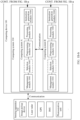
- FIG. 1A is a schematic diagram of a framework of a computing device according to an embodiment of the present invention.
- the computing device 100 shown in FIG. 1A includes a sensing apparatus 102, a computing system 104, and a microcontroller unit (microcontroller unit, MCU) 106.
- the computing system 104 may separately communicate with the sensing apparatus 102 and the microcontroller unit 106 by using a network.
- quantities of the sensing apparatuses 102, the computing systems 104, and the microcontroller units 106 are not limited.
- the quantity of the microcontroller unit 106 is less than or equal to the quantity of the computing system 104.
- each computing system may correspondingly communicate with one microcontroller unit, and one microcontroller unit may correspondingly communicate with one or more computing systems.
- two computing systems including a first computing system and a second computing system (shown as a computing system A and a computing system B) and one microcontroller unit are used as an example in the present invention.
- the sensing apparatus 102 is configured to detect an environment within a preset sensing scope, to collect corresponding sensor data.
- the sensor data collected by the sensing apparatus 102 may also be referred to as vehicle data.
- the preset sensing scope may specifically be defined by a system, and is limited by hardware of the sensing apparatus.
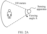
- FIG. 2A is a schematic diagram of a sensing scope of a sensing apparatus. As shown in FIG. 2A , the sensing scope that can be detected by the sensing apparatus is an area covered by using the sensing apparatus as an origin, a detection distance of 100 meters as a radius, and a radian of a viewing angle A.
- the sensing apparatus 102 may specifically be deployed inside or outside the computing device 100, for example, deployed in another device other than the computing device 100.
- this embodiment of the present invention is shown by using an example in which the sensing apparatus 102 is deployed in the another device other than the computing device 100.
- a deployment position and a deployment angle of the sensing apparatus 102 in the another device are possible within the scope of protection of the invention as defined by the claims.
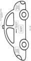
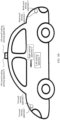
- FIG. 2B is a schematic diagram of a sensing apparatus deployment scenario.
- a device is a vehicle
- the sensing apparatus 102 may specifically be deployed in the front of the vehicle, for example, a forward sensing apparatus 1 shown in the figure.
- the sensing apparatus 102 may be deployed at the back of the vehicle, for example, a backward sensing apparatus 2 shown in the figure.
- the sensing apparatus 102 may be deployed at a left side of the vehicle, for example, a left sensing apparatus 3 shown in the figure.
- the sensing apparatus 102 may be deployed at a right side of the vehicle, for example, a right sensing apparatus 4 shown in the figure.
- the sensing apparatus 102 may be deployed at the top of a sunroof of the vehicle, and is used as an all-round looking sensing apparatus, for example, a sensing apparatus 5 shown in the figure, or the like.
- the sensing apparatus 102 may specifically be deployed in different subareas in a device.
- a quantity of subareas is not limited in the present invention, and there may be one or more subareas. Generally, there are at least two subareas.
- the subarea in the present invention may refer to a direction, and the subarea may specifically be defined by a system.
- a device is a vehicle.
- a system may deploy a sensing apparatus cluster in four subareas, and specifically, the subareas may be divided based on a direction of the vehicle, for example, a forward subarea, a backward subarea, a left subarea, and a right subarea of the vehicle.
- a sensing apparatus deployed in the forward subarea may also be referred to as a forward sensing apparatus
- a sensing apparatus deployed in the backward subarea may also be referred to as a backward sensing apparatus
- a sensing apparatus deployed in the left subarea may also be referred to as a left sensing apparatus
- a sensing apparatus deployed in the right subarea may also be referred to as a right sensing apparatus.
- the sensing apparatus 102 may specifically include but is not limited to an image pickup device (for example, a camera lens or a camera), a global positioning system (global positioning system, GPS), a laser radar sensor, a photosensitive sensing unit, an inertial measurement unit (inertial measurement unit, IMU), a temperature sensor, a barometric pressure sensor, another sensor used for environment measurement, or the like.
- an image pickup device for example, a camera lens or a camera
- global positioning system global positioning system, GPS
- a laser radar sensor for example, a laser radar sensor, a photosensitive sensing unit, an inertial measurement unit (inertial measurement unit, IMU), a temperature sensor, a barometric pressure sensor, another sensor used for environment measurement, or the like.
- IMU inertial measurement unit
- the sensor data collected by the sensing apparatus 102 varies with a type of the sensing apparatus 102.
- the image pickup device includes but is not limited to a camera lens, a camera, a camera module, and the like
- sensor data collected by the image pickup device may specifically be image data.
- the sensing apparatus 102 is a laser radar sensor
- sensor data collected by the laser radar sensor may specifically be laser point cloud data.
- the laser point cloud data is point cloud data obtained by scanning a target object by using the laser radar sensor.
- the point cloud data is recorded in a form of a point.
- Each point includes three-dimensional coordinates, and in addition to indicate a geometric position of the point, the three-dimensional coordinates may include depth information and the like.
- the sensing apparatus 102 may communicate with the computing system 104 by using a wired communications technology or a wireless communications technology.
- the wired communications technology may mean that two devices communicate with each other by using a network cable, an optical fiber, or the like.
- the wireless communications technology includes but is not limited to a global system for mobile communications (global system for mobile communications, GSM), a general packet radio service (general packet radio service, GPRS), code division multiple access (code division multiple access, CDMA), wideband code division multiple access (wideband code division multiple access, WCDMA), time-division code division multiple access (time-division code division multiple access, TD-SCDMA), long term evolution (long term evolution, LTE), wireless local area network (wireless local area networks, WLAN) (for example, a wireless fidelity (wireless fidelity, Wi-Fi) network), Bluetooth (bluetooth, BT), global navigation satellite system (global navigation satellite system, GNSS), frequency modulation (frequency modulation, FM), near field communication (near field communication, N
- the computing system 104 is configured to process sensor data collected by a group sensing apparatus that communicates with the computing system 104. Details about how to implement data processing are described below in the present invention.
- the group sensing apparatus herein includes one or more sensing apparatuses 102, sensor data collected by each group sensing apparatus is correspondingly processed by one computing system, and one computing system may correspondingly process sensor data collected by one or more group sensing apparatuses. It may be understood that, to ensure integrity or comprehensiveness of the sensor data, each group sensing apparatus needs to collect panorama data in a current environment, and therefore each group sensing apparatus needs to include at least one sensing apparatus in each subarea.
- each group sensing apparatus includes a forward sensing apparatus, a backward sensing apparatus, a left sensing apparatus, a right sensing apparatus, an all-round looking sensing apparatus, and the like.
- a quantity of the computing systems 104 is not limited, and there may be one or more computing systems.
- a sensing apparatus included in a group sensing apparatus corresponding to each computing system 104 may be the same or different.
- sensor data that is collected by a group sensing apparatus and that needs to be correspondingly processed by each computing system 104 may also be the same or different.
- any two computing systems may exchange intermediate data generated during data processing or result data generated after data processing.
- computing systems include a first computing system and a second computing system. The first computing system and the second computing system may exchange structured data and other data that are obtained by separately processing sensor data collected by a group sensing apparatus. This is described in detail below in the present invention.
- the computing system 104 is configured to process sensor data collected by a group sensing apparatus that communicates with the computing system 104.
- the group sensing apparatus may specifically include, but is not limited to, a graphics processing unit (graphics processing unit, GPU), a video card, a field programmable gate array (field-programmable gate array, FPGA) and a central processing unit (central processing unit, CPU), or other devices used for data processing.
- the computing system 104 (which is the computing system A or the computing system B shown in FIG. 1A ) specifically includes a management module 1041, a preprocessing module 1042, a processing module 1043, and an instruction generation module 1044.
- the computing system 104 further includes a selection module 1045.
- the management module 1041 is configured to manage data related to the computing system 104.
- the management module 1041 may be responsible for storing sensor data that is collected by a group sensing apparatus and that is received by the computing system 104, and regularly detecting the stored sensor data, for example, deleting sensor data whose storage duration exceeds preset duration, in other words, periodically clearing expired data.
- the preset duration is a longest buffer time of data, and may specifically be defined by a system, for example, the preset duration is an empirical value set based on user experience.
- the preprocessing module 1042 is configured to preprocess sensor data that needs to be processed by the computing system 104.
- the preprocessing includes but is not limited to data conversion, data screening (for example, removal of abnormal data), data encoding, data decoding, data correction, and the like.
- the sensor data is image data.
- the preprocessing may specifically be operation processing such as image scaling, image correction, or image stitching.
- the processing module 1043 is configured to process the preprocessed sensor data, to obtain structured data. Specifically, the processing module 1043 may perform calculation of a specified algorithm rule, such as a vector or a scalar, on the preprocessed sensor data, to detect and track a target object and therefore obtain corresponding structured data.
- the target object is a traffic light.
- the structured data includes but is not limited to information such as a quantity of traffic lights in a driving environment of a vehicle, a distance between the vehicle and the traffic light, and duration in which the traffic light allows the vehicle to pass.
- the instruction generation module 1044 is configured to process the structured data to control safe driving of the vehicle. Specifically, the instruction generation module 1044 may generate a corresponding control instruction based on the structured data obtained by the processing module 1043 by means of processing, and optionally, also based on information such as structured data obtained by another computing system 104 by means of processing, and vehicle positioning information. Further, safe driving of the vehicle is controlled according to the control instruction. For example, in FIG.
- the processing module 1043 in the computing system A and the processing module 1043 in the computing system B may exchange structured data obtained by means of respective processing, so that the instruction generation module 1044 in the computing system A or the computing system B can subsequently implement safety control of the vehicle based on the structured data obtained by the two computing systems by means of respective processing. Details are described below in the present invention.
- the computing system 104 may further include the selection module 1045.
- the selection module 1045 is configured to screen sensor data that is collected by at least one sensing apparatus and that is received by the computing system 104, to determine sensor data that is collected by a group sensing apparatus and that needs to be processed by the computing system 104.
- the selection module 1045 may select, according to a computing power balancing rule or a data volume balancing rule, a group sensing apparatus that needs to be processed by the computing system 104 from a plurality of sensing apparatuses that are communicatively connected to the computing system 104, to further process sensor data collected by the group sensing apparatus. If there are a plurality of computing systems, the computing device may ensure that computing power (or a data volume) of sensor data that is of a group sensing apparatus and that needs to be processed by each computing system is roughly the same.
- the computing power is used to measure a value of a data processing capability.
- a higher computing power indicates that a stronger or greater data processing capability is supported.
- a lower computing power indicates that a weaker data processing capability is supported.
- the data volume of the sensor data is in direct proportion to the computing power required for processing the sensor data.
- the computing power required is higher.
- the computing power required is lower.
- Related content is described below in the present invention by using the data volume as an example.
- related descriptions of the data volume are also applicable to descriptions of the computing power, and are not limited herein.
- FIG. 1A may include more or fewer components in an actual application, and FIG. 1A is only an example and constitutes no limitation.
- the microcontroller unit 106 is configured to control implementation of a corresponding management operation based on a processing result of the computing system 104.
- the microcontroller unit 106 may specifically control safe driving of the vehicle based on the processing result of the computing system 104.
- the microcontroller unit 106 may monitor a running status of each computing system 104, to control safe driving of the vehicle based on the running status and a processing result of each computing system 104.
- the running status is used to indicate a running condition of a computing system, for example, normal or faulty.
- the running status specifically includes a health state and a fault state.
- the microcontroller unit 104 may control safe driving of the vehicle by using a processing result of a computing system 104 whose running status is a health state. Details are described below in the present invention.
- the microcontroller unit 106 may obtain the running status of the computing system 104 by monitoring software or hardware deployed in the computing device.
- the software deployed in the computing device includes but is not limited to application software customized and installed by a user, or system software deployed in the computing device, for example, an operating system OS.
- the microcontroller unit may report a fault notification message in real time or periodically, to notify that the computing system has a critical fault.
- the computing device may determine that the running status of the computing system is a fault state; otherwise, the computing device determines that the running status of the computing system is a health state.
- the computing device may further determine the running status of the computing system based on a quantity of times that the computing device receives the fault notification message. Specifically, when the quantity of times that the computing device receives the fault notification message is greater than or equal to a preset quantity of times, it may be determined that the running status of the computing system is a fault state.
- the preset quantity of times is defined by a system, for example, customized based on a user requirement or a preference. When the quantity of times that the computing device receives the fault notification message is less than the preset quantity of times, it may be considered that the fault notification message is falsely triggered and reported, and the running status of the computing system may be a health state.
- the computing device may monitor, in real time or periodically, whether hardware related to the computing system is faulty. For example, when hardware, such as a key interface (for example, a communications interface), a power supply, and a clock that are deployed in the computing system, is faulty, the computing system may automatically report a fault notification message to notify that the computing system is faulty. Correspondingly, after receiving the fault notification message, the computing device may determine that the computing system is faulty; otherwise, the computing device determines that the computing system is not faulty. Optionally, to avoid false reporting, the computing device may further determine the running status of the computing system by considering a quantity of times of that the computing device receives the fault notification message. For details, refer to related descriptions in the foregoing embodiment.
- the computing device may determine the running status of the computing system based on a time interval between a current time of the system and a time at which a heartbeat packet sent by hardware is received last time. For example, when the time interval is greater than or equal to preset duration, the computing device may determine that the running status of the computing system is a fault state; otherwise, the computing device determines that the running status of the computing system is a health state, and the like.
- the microcontroller unit 106 and the computing system 104 may exchange heartbeat packets (namely, heartbeat messages) to detect a running status of the computing system 104.
- the heartbeat message (heartbeat message) is a message sent by a sender to a receiver, and the receiver may determine, based on the message, whether and when the sender is faulty or terminated.
- the heartbeat message starts to be sent when the sender starts, until the sender is powered off and stops running. In this period, the sender sends a message to the receiver periodically or in real time. If the receiver does not receive a message within a message receiving period, the receiver may consider that the sender is faulty or currently unavailable.
- the receiver may feed back a corresponding response message to the sender.
- the sender may determine, based on the response message, whether the receiver is faulty.
- the computing system 104 may send a heartbeat message in real time or periodically to the microcontroller unit 106 that communicates with the computing system 104.
- the microcontroller unit 106 detects that no heartbeat message sent by the computing system 104 is received within a message receiving period, it may be determined that the computing system 104 is faulty, in other words, the running status of the computing system 104 is a fault state. Otherwise, it is determined that the running status of the computing system 104 is a health state.
- the microcontroller unit 106 may actively send a heartbeat message to the computing system 104 that communicates with the microcontroller unit 106.
- the microcontroller unit 106 may receive a response message sent by the computing system 104, it may be determined that the running status of the computing system 104 is a health state, in other words, the computing system 104 is not faulty.
- the microcontroller unit 106 does not receive the response message sent by the computing system 104, it may be determined that the running status of the computing system 104 is a fault state, in other words, the computing system 104 is faulty.
- microcontroller unit 106 there may specifically be one or more microcontroller units 106.
- the microcontroller unit 106 is configured to manage all the computing systems 104, to implement a corresponding device management operation.
- one microcontroller unit communicates with two computing systems, and is configured to manage processing results of the two computing systems, to implement a corresponding device management operation.
- Each microcontroller unit 106 may be configured to manage one or more computing systems 104, and each computing system 104 may be correspondingly managed by one microcontroller unit 106. Any two microcontroller units 106 may exchange running statuses of computing systems separately monitored by the microcontroller units 106, so that the computing device can determine a computing system 104 whose running status is a health state, and further control safe driving of the vehicle based on a processing result obtained by the computing system 104 whose running status is a health state.
- FIG. 1B-b are a schematic diagram of a structure of another computing device.
- the computing device is shown by using two computing systems and two microcontroller units as an example.
- the two computing systems are respectively a computing system A and a computing system B
- the two microcontroller units are respectively a microcontroller unit A and a microcontroller unit B.
- the microcontroller unit A communicates with the computing system A, and is configured to manage and monitor the computing system A.
- the microcontroller unit B communicates with the computing system B, and is configured to manage and monitor the computing system B.
- the microcontroller unit A and the microcontroller unit B may mutually exchange running statuses of the computing systems separately monitored by the microcontroller unit A and the microcontroller unit B. Assuming that the running status of the computing system A is a fault state (in other words, the computing system A is faulty and is unavailable), by exchanging the statuses between the microcontroller unit A and the microcontroller unit B, the microcontroller unit B may determine that the running status of the computing system B is a health state, and the running status of the computing system A is a fault state, and the microcontroller unit B may obtain a processing result of the computing system B, to control safe driving of a vehicle based on the processing result. Details about the processing result and how to control safe driving of the vehicle based on the processing result are described below in the present invention.
- the microcontroller unit 106 specifically includes a monitoring module 1061, an arbitration module 1062, and an interconnection module 1063.
- the monitoring module 1061 is configured to monitor a running status of at least one computing system 104 that communicates with the microcontroller unit 106. Specifically, the monitoring unit 1061 may obtain, by means of monitoring, the running status of the computing system 104 by using hardware, software, a heartbeat message, or the like. For details about how the monitoring unit 1061 obtains the running status of the computing system 104 by means of monitoring, refer to related descriptions in the foregoing embodiment. Details are not described herein again.
- the arbitration module 1062 is configured to determine, based on the running status that is of the computing system 104 and that is obtained by the monitoring module 1061 by means of monitoring, whether the computing system 104 is faulty, and further notify the interconnection module 1063 whether to control safe driving of the vehicle according to a control instruction generated by the computing system 104 that is not faulty. Specifically, when determining that the running status of the computing system that communicates with the microcontroller unit 106 is a health state (in other words, the computing system is not faulty), the arbitration module 1062 may notify the interconnection module 1063 to control safe driving of the vehicle according to a control instruction generated by the computing system.
- the arbitration module 1062 may end a process or report a fault notification message that is used to notify that the computing system is faulty.
- the interconnection module 1063 is configured to control safe driving of the vehicle. Specifically, after receiving a notification from the arbitration module 1062, the interconnection module 1063 may control safe driving of the vehicle according to the control instruction generated by the computing system 104 that is not faulty.
- one microcontroller unit 1061 is deployed in the computing device, and the one microcontroller unit 1061 is responsible for interconnecting with/managing a plurality of computing systems 104.
- the one microcontroller unit 1061 is responsible for interconnecting with/managing a plurality of computing systems 104.
- the arbitration module 1062 determines, based on running statuses of a plurality of computing systems, a computing system whose running status is a health state (in other words, a computing system that is not faulty).
- the interconnection module 1063 controls safe driving of the vehicle according to a control instruction that is generated by the determined computing system.
- one microcontroller unit 106 is configured to manage two computing systems (the computing system A and the computing system B).
- the microcontroller unit 106 separately obtains a running status of the computing system A and a running status of the computing system B by means of monitoring by using the monitoring module 1061, and sends the running statuses to the arbitration module 1062 for arbitration.
- a quantity of the monitoring modules 1061 in the microcontroller unit 106 is not limited. Using two monitoring modules 1061 as an example, the microcontroller unit 1061 obtains the running status of the computing system A by means of monitoring by using one monitoring module, and obtains the running status of the computing system B by means of monitoring by using the other monitoring module.
- the arbitration module 1062 determines, based on the received running statuses of the computing system A and the computing system B, a computing system whose running status is a health state, in other words, determines a computing system that is not faulty. Further, the interconnection module 1063 controls safe driving of the vehicle according to a control instruction that is generated by the determined computing system. For example, assuming that the computing system A is faulty or the computing system B is not faulty, the arbitration module 1062 may determine that the running status of the computing system B is a health state, and further controls safe driving of the vehicle by using the interconnection module 1063 and according to a control instruction generated by the computing system B.
- a plurality of microcontroller units 1061 are deployed in the computing device, and each microcontroller unit 1061 is responsible for managing one computing system 104.
- a monitoring module 1061 in each microcontroller unit 106 is responsible for monitoring a running status of one computing system.
- the plurality of microcontroller units 106 may exchange running statuses of computing systems monitored by the plurality of microcontroller units 106.
- any microcontroller unit 106 determines, by using an arbitration module 1062 of the microcontroller unit 106 and based on running statuses of a plurality of computing systems that are received and obtained by means of monitoring by the microcontroller unit 106, a computing system whose running status is a health state. Therefore, the computing device controls safe driving of the vehicle by using the microcontroller unit 106 that is correspondingly managed by the determined computing system and using an interconnection module 1063 in the microcontroller unit 106 and according to a control instruction generated by the determined computing system.
- two microcontroller units are configured to interconnect with and manage two computing systems.
- the microcontroller unit A manages the computing system A
- the microcontroller unit B manages the computing system B.
- Specific schematic diagrams of structures of the microcontroller unit A and the microcontroller unit B each include a monitoring module 1061, an arbitration module 1062, and an interconnection module 1063.
- the monitoring module 1061 in the microcontroller unit A may obtain a running status of the computing system A by means of monitoring
- the monitoring module 1061 in the microcontroller unit B may obtain a running status of the computing system B by means of monitoring.
- the microcontroller unit A and the microcontroller unit B may exchange the running statuses of the computing systems that are respectively obtained by the microcontroller unit A and the microcontroller unit B.
- both the microcontroller unit A and the microcontroller unit B can learn the running status of the computing system A and the running status of the computing system B.
- the arbitration modules 1062 in the microcontroller unit A and the microcontroller unit B each may determine, based on the running statuses of the computing systems A and B, a computing system whose running status is a health state, for example, the computing system A or the computing system B.
- the running status of the computing system A is a health state
- the running status of the computing system B is a fault state.
- the computing device may select the microcontroller unit A that communicates with the computing system A to control implementation of safe driving of the vehicle.
- the computing device may control safe driving of the vehicle by using the interconnection module 1063 in the microcontroller unit A and according to a control instruction generated by the computing system A.
- each microcontroller unit 106 may exchange a primary-secondary relationship of the computing systems, to further control safe driving of the vehicle based on the interconnection module 1063 in the microcontroller unit 106 that is correspondingly managed by a primary computing system. For example, in the example in FIG. 1B-a and FIG.
- the microcontroller unit A and the microcontroller unit B may further exchange attribute information (which may specifically be attribute information used to describe a primary-secondary relationship of the computing systems) of the computing systems respectively monitored by the microcontroller unit A and the microcontroller unit B.
- attribute information which may specifically be attribute information used to describe a primary-secondary relationship of the computing systems
- the running statuses of the computing system A and the computing system B each are a health state
- the computing system A is a primary computing system
- the computing system B is a secondary computing system.
- the microcontroller unit A and the microcontroller unit B may learn, by exchanging information, that neither the computing system A nor the computing system B is faulty, and the computing system A is the primary computing system. Further, the computing device may determine to control implementation of safe driving of the vehicle by using the microcontroller unit A that interconnects with and manages the computing system A. Specifically, the computing device controls safe driving of the vehicle by invoking the interconnection unit 1063 in the microcontroller unit B and according to a control instruction generated by the primary computing system A.
- each module or each unit shown in FIG. 1A or FIG. 1B-a and FIG. 1B-b may specifically be implemented by using software or hardware.
- each module or each unit shown in the figure may specifically be a software module.
- each module or each unit shown in the figure may specifically be implemented by using an application-specific integrated circuit (application-specific integrated circuit, ASIC), or a programmable logic device (programmable logic device, PLD).
- ASIC application-specific integrated circuit
- PLD programmable logic device
- the PLD may be a complex programmable logical device (complex programmable logical device, CPLD), a field programmable gate array (field-programmable gate array, FPGA), a generic array logic (generic array logic, GAL), or any combination thereof.
- complex programmable logical device complex programmable logical device, CPLD
- field programmable gate array field-programmable gate array
- GAL generic array logic
- the computing device in this embodiment of the present invention may specifically include but is not limited to any one of the following: a vehicle, a mobile phone, a tablet personal computer (tablet personal computer), a personal digital assistant (personal digital assistant, PDA), a mobile internet device (mobile internet device, MID), a wearable device (wearable device), a vehicle-mounted device, another device that supports network communications, or the like.
- a vehicle a mobile phone, a tablet personal computer (tablet personal computer), a personal digital assistant (personal digital assistant, PDA), a mobile internet device (mobile internet device, MID), a wearable device (wearable device), a vehicle-mounted device, another device that supports network communications, or the like.
- Step S402 A computing device determines first vehicle data that needs to be processed by a first computing system and second vehicle data that needs to be processed by a second computing system.
- the first vehicle data is environment data that is within a first sensing scope and that is detected by a first group sensing apparatus at a first time point
- the second vehicle data is environment data that is within a second sensing scope and that is detected by a second group sensing apparatus at the first time point.
- the sensing apparatuses included in the first group sensing apparatus and the second group sensing apparatus may be the same or different.
- the first sensing scope correspondingly detected by the first group sensing apparatus and the second sensing scope correspondingly detected by the second group sensing apparatus may also be the same or different.
- a preset sensing scope (for example, the first sensing scope or the second sensing scope) corresponding to each group sensing apparatus may specifically be a 360-degree panoramic visual scope in an environment of the vehicle, in other words, each group sensing apparatus can collect panorama data in the current environment within the panoramic visual scope.
- the sensing apparatus in the present invention may be deployed in a device by using a group concept.
- a quantity of groups needs to be less than or equal to a quantity of computing systems, to ensure that each computing system correspondingly processes sensor data collected by one group sensing apparatus, and the sensor data collected by each group sensing apparatus may be processed by one or more computing systems.
- a rule of group deployment of sensing apparatuses may specifically include at least one of the following: 1.
- Each group sensing apparatus can collect panorama data in a current environment.
- the panorama data in the current environment may be collected by using another group sensing apparatus, and the panorama data herein refers to data obtained by the group sensing apparatus by scanning and detecting a panorama (a 360-degree scene) of the current environment.
- a data volume of sensor data collected by each group sensing apparatus is roughly the same. In other words, a difference between data volumes of sensor data collected by any two group sensing apparatuses is less than or equal to a preset threshold.
- the preset threshold is defined by a system, for example, an empirical value set based on user experience, or obtained by means of statistics collection based on a series of experimental data.
- each sensing apparatus may be in communication connection with one or more computing systems.
- the communication connection may specifically be a wired connection or a wireless connection.
- the computing device may deploy, by using the foregoing rule of group deployment of sensing apparatuses, each group sensing apparatus that meets a requirement for panoramic data obtaining and/or data volume balancing as being communicatively connected to a corresponding computing system in a wired manner. Therefore, the computing system can subsequently directly determine, based on a wired communication connection mode, sensor data that is collected by a group sensing apparatus and that needs to be processed by the computing system.
- the computing device may select, by using the foregoing rule of group deployment of sensing apparatuses and using software and from all sensing apparatuses that communicate with the computing system, one group sensing apparatus that can meet a requirement for panorama data obtaining and/or data volume balancing, and further determines that the computing system is responsible for processing sensor data collected by the group sensing apparatus.
- the subarea A may be a forward subarea
- the subarea B may be a backward subarea
- the subarea C may be a side subarea, and may specifically include a left side subarea, a right side subarea, and the like.
- Three sensing apparatuses are included (deployed) in each subarea: a sensing apparatus 1, a sensing apparatus 2, and a sensing apparatus 3.
- each sensing apparatus in the three subareas may be connected to the computing system A and the computing system B.
- the computing device may group the sensing apparatuses in the three subareas by using software, to ensure that a first group sensing apparatus corresponding to the computing system A and a second group sensing apparatus corresponding to the computing system B can collect panorama data, and can meet a data volume balancing rule.
- the first group sensing apparatus includes a sensing apparatus 1 in a subarea 1, sensing apparatuses 2 and 3 in a subarea 2, and a sensing apparatus 1 in a subarea 3.
- the second group sensing apparatus includes sensing apparatuses 2 and 3 in the subarea 1, a sensing apparatus 1 in the subarea 2, and sensing apparatuses 2 and 3 in the subarea 3.
- the computing device may deploy the sensing apparatuses in FIG. 3B by using the foregoing rule of group deployment of sensing apparatuses.
- the computing system A can process the sensor data collected by the first group sensing apparatus
- the computing system B can process the sensor data collected by the second group sensing apparatus.
- a correspondence also referred to as an association relationship or a binding relationship
- the computing system can determine, based on the correspondence, sensor data (namely, vehicle data) that is collected by the group sensing apparatus and that needs to be processed by the computing system.
- the correspondence may specifically be defined by a system, or may be customized by a user based on an actual requirement or a personal preference.
- the computing device may match in advance, according to the foregoing rule of group deployment of sensing apparatuses, a group sensing apparatus that meets a requirement of panorama data obtaining and/or data volume balancing to a corresponding computing system.
- the computing device when deploying the group sensing apparatus, directly deploys the group sensing apparatus as a sensing apparatus connected to the computing system in a wired manner, or creates a correspondence between the group sensing apparatus and the computing system, for example, stores the correspondence in a form of a text or a table.
- the computing device may determine, based on a pre-stored correspondence between the first computing system and the first group sensing apparatus, that vehicle data that needs to be processed by the first computing system is the sensor data collected by the first group sensing apparatus, specifically, the sensor data that is obtained by the first group sensing apparatus by detecting the current environment within the first sensing scope.
- the computing device may determine, based on a pre-stored correspondence between the second computing system and the second group sensing apparatus, that vehicle data that needs to be processed by the second computing system is the sensor data collected by the second group sensing apparatus, specifically, the sensor data that is obtained by the second group sensing apparatus by detecting the current environment within the second sensing scope.
- the computing device may learn, according to the foregoing rule of group deployment of sensing apparatuses, that the step S402 may be specifically implemented in the following several manners.
- the computing device determines, based on a data volume of sensor data collected by a sensing apparatus, sensor data that is collected by a group sensing apparatus and that is correspondingly processed by a computing system, to ensure that a data volume of sensor data processed by each computing system is roughly the same.
- a difference between data volumes of sensor data that needs to be processed by any two computing systems is less than or equal to a preset threshold, and the preset threshold is defined by a system.
- the computing systems may allocate sensing apparatuses according to a data volume balancing rule.
- the first vehicle data that needs to be processed by the first computing system is the sensor data collected by the first group sensing apparatus
- the second vehicle data that needs to be processed by the second computing system is the sensor data collected by the second group sensing apparatus.
- a difference between a data volume of the first vehicle data and a data volume of the second vehicle data is less than or equal to the preset threshold, for example, 0.
- the sensing apparatuses are image pickup devices, and resolutions of image data collected by different image pickup devices may be different.
- computing power (or a data volume of the image data) required when the computing device processes the image data of the resolutions by using the computing systems is also different.
- five image pickup devices are deployed in the computing device: an image pickup device A, an image pickup device B, an image pickup device C, an image pickup device D, and an image pickup device E.
- the resolution of the image pickup device A is 3840 x 2160
- the resolution of the image pickup device B and the resolution of the image pickup device C are both 1920 x 1080
- the resolution of the image pickup device D and the resolution of the image pickup device E are both 960 x 540.
- the computing device may use the image pickup device A and the image pickup device D as the first group sensing apparatus, and allocate the first group sensing apparatus to the first computing system; and the computing device may use the image pickup devices B, C, and E as the second group sensing apparatuses, and allocate the second group sensing apparatuses to the second computing system.
- a data volume balancing namely, computing power balancing
- the computing device processes, by using the first computing system, image data collected by the first group sensing apparatus (which may specifically be the image pickup devices A and D), and processes, by using the second computing system, image data collected by the second group sensing apparatus (which may specifically be the image pickup devices B, C, and E).
- the computing device may determine, based on deployment positions of different sensing apparatuses, sensor data that is collected by a group sensing apparatus and that needs to be processed by a computing system, to use the sensor data as vehicle data that needs to be processed by the computing system.
- the group sensing apparatus includes one or more sensing apparatuses. To ensure comprehensiveness of data coverage, each group sensing apparatus includes a sensing apparatus deployed in each direction (or subarea).
- the direction herein refers to a deployment direction of the sensing apparatus, and may specifically be defined and deployed by a system.
- a group sensing apparatus corresponding to each computing system includes the forward sensing apparatus, the backward sensing apparatus, the left sensing apparatus, the right sensing apparatus, the all-round looking sensing apparatus, and the like in the example shown in FIG. 2B .
- each computing system can control or interconnect with group sensing apparatuses that are deployed in all directions, so that after any computing system in the computing device is faulty, a computing system that is not faulty can collect panorama data in the current environment based on a group sensing apparatus corresponding to the computing system, and therefore controls safe driving of the vehicle, and the like. This helps improve driving safety of the vehicle.
- the computing systems include the first computing system and the second computing system. It is assumed that in the computing device, sensing apparatuses are deployed in five subareas: a subarea A, a subarea B, a subarea C, a subarea D, and a subarea E.
- Three forward sensing apparatuses (which may specifically be forward sensing apparatuses 1 to 3) are deployed in the subarea A, two backward sensing apparatuses (which may specifically be backward sensing apparatuses 1 and 2) are deployed in the subarea B, two left sensing apparatuses (which may specifically be left sensing apparatuses 1 and 2) are deployed in the subarea C, four right sensing apparatuses (which may specifically be right sensing apparatuses 1 to 4) are deployed in the subarea D, and two all-round looking sensing apparatuses are deployed in the subarea E.
- the computing device may use the forward sensing apparatuses 1 and 2 in the subarea A, the backward sensing apparatus 2, the left sensing apparatus 1, the right sensing apparatuses 1 and 2, and an all-round looking sensing apparatus 1 as the first group sensing apparatus, and allocates the first group sensing apparatus to the first computing system, in other words, uses data collected by the first group sensing apparatus as the first vehicle data that needs to be processed by the first computing system.
- the computing device may use the forward sensing apparatus 3 in the subarea A, the backward sensing apparatus 1, the left sensing apparatus 2, the right sensing apparatuses 3 and 4, and an all-round looking sensing apparatus 2 as the second group sensing apparatus, and allocates the second group sensing apparatus to the second computing system, in other words, uses data collected by the second group sensing apparatus as the second vehicle data that needs to be processed by the second computing system.
- detection scopes of any two sensing apparatuses deployed in a same direction may be the same, may be different, or may be not totally the same, for example, some parts of the detection scopes overlap.
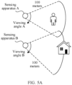
- FIG. 5A is a schematic diagram of a detection scenario of two forward sensing apparatuses. As shown in FIG.
- a detection scope of a sensing apparatus A is an area covered by using a detection distance of 100 meters and a viewing angle A
- a detection scope of a sensing apparatus B is an area covered by using a detection distance of 100 meters and a viewing angle B.
- the detection scopes of the sensing apparatus A and the sensing apparatus B are not totally the same, and some areas overlap.
- the computing device may further combine the first and second implementations. when data volume balancing is met, the computing device may further consider deployment positions of different sensing apparatuses, to allocate sensor data collected by the group sensing apparatuses that are deployed in all directions to a same computing system for processing.
- the computing device may further determine, based on attribute information of different sensing apparatuses, sensor data that is collected by a group sensing apparatus and that needs to be processed by each computing system, to use the sensor data as vehicle data that needs to be processed by the computing system. Specifically, the computing device may use at least one sensing apparatus having same attribute information as one group sensing apparatus, and allocates data collected by the group sensing apparatus to a same computing system for processing.
- the attribute information is specifically information used to describe an attribute of a sensing apparatus, for example, the attribute information may include but is not limited to a working frequency (which may also be referred to as a sampling frequency) of the sensing apparatus, a type of the sensing apparatus, a category to which the sensing apparatus belongs, a function of the sensing apparatus, and the like.
- a working frequency which may also be referred to as a sampling frequency
- the sensing apparatus includes a radar sensor, an image pickup device, and a laser measurement unit.
- a data volume of sensor data collected by the radar sensor within a unit time is Q1
- a data volume of sensor data collected by the image pickup device within a unit time is Q2
- a data volume of sensor data collected by the laser measurement unit within a unit time is Q3.
- the computing device may use the radar sensor and the laser measurement unit as the first group sensing apparatus, to allocate sensor data collected by the first group sensing apparatus to the first computing system for processing, and may use the image pickup device as the second group sensing apparatus, and allocate sensor data collected by the second group sensing apparatus to the second computing system for processing.
- the computing device may further determine, both in the first implementation and/or the second implementation, vehicle data that needs to be correspondingly processed by a computing system. For example, the computing device may determine, based on both attribute information of a sensing apparatus and a data volume of sensor data collected by the sensing apparatus, sensor data that is collected by a group sensing apparatus and that needs to be processed by each computing system, to use the sensor data as vehicle data that needs to be processed by the computing system. Therefore, the computing device ensures that the data volume of the sensor data that needs to be processed by each computing system is balanced, and that group sensing apparatuses corresponding to a same computing device have same attribute information.
- both the first vehicle data and the second vehicle data in the present invention are sensor data collected by group sensing apparatuses, and may be the same or may be different depending on the group sensing apparatuses that respectively collect the first vehicle data and the second vehicle data.
- the first vehicle data or the second vehicle data may include but is not limited to radar data collected by using a radar sensor, laser data collected by using a laser measurement unit, location data collected by using a GPS, photosensitive data collected by using a photosensitive unit, and the like.
- Step S404 The computing device processes the first vehicle data by using the first computing system, to obtain first structured data, where the first structured data is used to represent an environment that is of a vehicle at the first time point and that is detected by the first group sensing apparatus.
- the computing device may process the second vehicle data by using the second computing system, to obtain second structured data, where the second structured data is used to represent an environment that is of the vehicle at the first time point and that is detected by the second group sensing apparatus.
- the first computing system may obtain the first vehicle data, and further process the first vehicle data, to obtain the corresponding first structured data.
- the processing includes but is not limited to preprocessing, object recognition, object detection, and the like.
- the first computing system may preprocess the first vehicle data, to obtain preprocessed first vehicle data.
- the preprocessing herein may be defined by a system, and may include but is not limited to data screening, abnormal value removal, data conversion, and the like.
- the first vehicle data is image data collected by an image pickup device.
- the preprocessing includes but is not limited to image conversion, image stitching, image correction, image warping, other image processing, or the like.
- the computing device may continue to process the preprocessed first vehicle data, to obtain the first structured data.
- the computing device may process the preprocessed first vehicle data by using a first preset algorithm, to obtain the first structured data, where the first structured data is used to indicate the environment that is of the vehicle at the first time point and that is detected by the first group sensing apparatus.
- the first preset algorithm is defined by a system, or is pre-trained by the computing device, and is used to identify a current environment of the vehicle.
- the first structure data includes but is not limited to an obstacle, another vehicle, a lane line, a lane width, a traffic light, a distance between a traffic light and the vehicle, a distance between the vehicle and the another vehicle, other data that reflects an environment of the vehicle, or the like.
- the first preset algorithm is a neural network algorithm.
- the first computing system may analyze the first vehicle data by using the neural network algorithm, to complete detection and tracking of a target object, and obtain the first structured data.
- the used first preset algorithm may also be different.
- the first preset algorithm may be an algorithm that is pre-trained by a system and that is deployed in the computing device, to wait to be directly loaded and used when the target object is detected.
- the target object is a traffic light
- the first preset algorithm may be a convolutional neural network algorithm
- the first structured data includes information such as a traffic light, a distance between the traffic light and the vehicle, and duration of displaying each traffic light in a driving environment of the vehicle.
- the first computing system may manage the first vehicle data.
- the first computing system may store the first vehicle data in a cache of the first computing system.
- the first computing system may delete the stored first vehicle data in real time or periodically, for example, clear the first vehicle data whose storage duration exceeds preset duration, in other words, clear expired data in real time or periodically.
- the preset duration is defined by a system, for example, set based on an actual requirement of a user.
- first structured data and the second structured data in the present invention are used to represent an environment that is of the vehicle at the first time point and that is detected by a group sensing apparatus.
- the first structured data and the second structured data may be the same, or may be different, depending on their respective corresponding group sensing apparatuses.
- the first structured data obtained by the first computing system may be different from the second structured data obtained by the second computing system.
- Step S406 The computing device controls safe driving of the vehicle based on the first structured data and the second structured data.
- the first structured data and the second structured data may be structured data obtained after the computing device processes sensor data collected by different group sensing apparatuses, but not the sensor data collected by all the group sensing apparatuses.
- the computing systems may exchange the structured data obtained by the computing systems. Therefore, the computing device can control safe driving of the vehicle based on the structured data obtained by each computing system by processing.
- the computing systems include the first computing system and the second computing system.
- the first computing system and the second computing system in the present invention may exchange the obtained first structured data and second structured data.
- the first computing system may actively send a data request to the second computing system based on an actual requirement, to obtain the second structured data.
- the second computing system may broadcast the second structured data to another computing system, so that the another computing system obtains and uses the second structured data.
- the second computing system may also obtain the first structured data processed by the first computing system. Details are not described herein again.
- the computing device controls safe driving of the vehicle based on the first structured data and the second structured data by using the first computing system or the second computing system.
- the computing device may control safe driving of the vehicle according to control instructions respectively generated by the two computing systems.
- the control instructions are generated by the computing systems based on the first structured data and the second structured data.
- the computing device may obtain a running status of each of the first computing system and the second computing system by means of monitoring by using a microcontroller unit. Further, the computing device determines, based on the running statuses of the first computing system and the second computing system, whether the first computing system and the second computing system are faulty. For details about how the computing device determines, by using a microcontroller unit, whether the first computing system or the second computing system is faulty, refer to the related descriptions in FIG. 1A or FIG. 1B-a and FIG. 1B-b . Details are not described herein again.
- the first computing system may obtain a first control instruction based on the first structured data and the second structured data, and the first control instruction is used to control safe driving of the vehicle.
- the first computing system may perform smoothing processing on the first structured data and the second structured data, to obtain road feature information of vehicle driving, for example, information about a location of a surrounding vehicle, a lane line, a lane quantity, a road sign, a lane width, and an area in which the vehicle can travel.
- the first computing system generates the first control instruction based on the road feature information and positioning information of the vehicle.
- the positioning information may specifically be location information that is of the vehicle in a real space and that is collected by using a positioning apparatus.
- the positioning apparatus includes at least one of the following: a GPS, an IMU, a wheel speedometer, another component used for positioning, or the like.
- the first control instruction is generated based on the first structured data and the second structured data of the vehicle when the vehicle is in the environment at the first time point, and the first control instruction is used to control safe driving of the vehicle. It may be understood that the generated first control instruction may vary with changes of the environment. For example, in a scenario in which the vehicle drives through a curve, the generated first control instruction may specifically be used to indicate information such as a current turning direction and a current turning angle of the vehicle, to implement safe driving of the vehicle in a curve.
- the generated first control instruction may specifically be used to indicate a lane on which the vehicle travels, a vehicle speed, a vehicle spacing that needs to be maintained between the vehicle and another vehicle, and the like, to ensure that the vehicle implements safe driving in a congestion environment.
- an operation object that is correspondingly indicated by the first control instruction and that is in the vehicle includes but is not limited to components such as a brake, an accelerator, a steering wheel, a gear, a turn light, a fog light, a rain wiper, and the like of the vehicle.
- Operation processing indicated by the first control instruction includes but is not limited to speed control, route change, lane change, turning angle control, and the like.
- the computing device implements driveway change (namely, lane change) by controlling the steering wheel, and indicates, to the vehicle by controlling the turn light, a direction for lane change that needs to be currently performed, to avoid a traffic accident, and ensure driving safety of the vehicle.
- the second computing system may also obtain a second control instruction based on the first structured data and the second structured data.
- control instructions generated by different computing systems may vary with different computing systems that have different data processing precision and use different algorithms during data processing.
- the first control instruction and second control instruction in the foregoing descriptions of the present invention may be different.
- the computing device may determine a vehicle control instruction according to the first control instruction generated by the first computing system and the second control instruction generated by the second computing system, and further controls safe driving of the vehicle based on the vehicle control instruction. Specifically, the computing device may randomly select one of the first control instruction and the second control instruction that are separately generated by the two computing systems as the vehicle control instruction. Alternatively, the computing device may select, based on a primary-secondary relationship between the computing systems and from the first control instruction and the second control instruction that are separately generated by the two computing systems, a control instruction generated by a primary computing system as the vehicle control instruction.
- the primary-secondary relationship between the computing systems is pre-defined by a system, for example, defined based on a user requirement or a user preference.
- a system for example, defined based on a user requirement or a user preference.
- the computing device may determine that the first control instruction generated by the first computing system is the vehicle control instruction, to subsequently control safe driving of the vehicle according to the vehicle control instruction.
- the computing device may generate the first control instruction based on the first structured data and the second structured data by using the first computing system, and further controls safe driving of the vehicle according to the first control instruction.
- the first control instruction may be generated based on the first structured data and the second structured data by using the first computing system, and further controls safe driving of the vehicle according to the first control instruction.
- the computing device may process, by using another computing system that is not faulty, vehicle data that needs to be processed, to control safe driving of the vehicle.
- vehicle data vehicle data
- sensor data vehicle data
- the computing system that is not faulty because there is a relatively large amount of vehicle data, and the computing system is limited by computing power or hardware of the computing system, the computing system cannot meet a processing requirement of a large amount of vehicle data.
- dimension reduction processing (which may also be referred to as optimization processing) needs to be first performed on the vehicle data, to obtain processed vehicle data, and further implement safe driving of the vehicle based on the processed vehicle data.
- Step S602 The second computing system obtains third vehicle data and fourth vehicle data, where the third vehicle data is environment data that is within a first sensing scope and that is detected by a first group sensing apparatus at a second time point.
- the fourth vehicle data is environment data that is within a second sensing scope and that is detected by a second group sensing apparatus at the second time point.
- Step S604 The second computing system performs dimension reduction processing on the third vehicle data and the fourth vehicle data, to obtain the third vehicle data after dimension reduction and the fourth vehicle data after dimension reduction.
- the dimension reduction processing mentioned above in the present invention refers to operation processing performed to reduce a computing volume of a computing system, and may include: resolution reduction, frame rate reduction, reduction of a quantity of sensing apparatuses. The following uses an example for description.
- all vehicle data (which may specifically include the third vehicle data and the fourth vehicle data) that needs to be processed by the second computing system is frame image data collected by using an image pickup device.
- the vehicle data that needs to be processed by the second computing system includes a plurality of frames of images.
- the second computing system may perform frame rate reduction on the plurality of frames of images that need to be processed, to obtain processed frame images with small data volumes.
- the second computing system may remove even frames of images, and retain odd frames of images as the processed frame images or the like.
- all vehicle data (which may specifically include the third vehicle data and the fourth vehicle data) that needs to be processed by the second computing system is frame image data collected by using an image pickup device.
- the vehicle data that needs to be processed by the second computing system includes a plurality of frames of images.
- the second computing system may perform resolution reduction on the plurality of frames of images that need to be processed, to obtain processed frame images with small data volumes.
- the second computing system may use a preset image algorithm to convert a frame image of first resolution into a frame image of second resolution. The first resolution is greater than the second resolution.
- the preset image algorithm is defined by a system, is used to reduce resolution of an image frame, and may include but is not limited to an image compression algorithm, an image reconstruction algorithm, another algorithm used to reduce resolution, or the like.
- the reduction of a quantity of sensing apparatuses in the present invention refers to reducing a quantity of sensing apparatuses included in a group sensing apparatus, to reduce sensor data that is collected by using a sensing apparatus and that needs to be processed by a computing system.
- both the third vehicle data and the fourth vehicle data that need to be processed by a computing system are sensor data collected by using the group sensing apparatus.
- the second computing system may perform screening processing (namely, reduction of a quantity of sensing apparatuses) on the third vehicle data and the fourth vehicle data that are collected by a plurality of sensing apparatuses included in the group sensing apparatus, to be specific, sensor data collected by some sensing apparatuses is discarded, to obtain sensor data collected by a relatively small quantity of sensing apparatuses, and use the sensor data as processed vehicle data.
- the relatively small quantity of sensing apparatuses can scan and detect panorama data of a current environment of a vehicle. In other words, if the second computing system supports panorama, the second computing system may select some sensing apparatuses from the plurality of sensing apparatuses, and use sensor data collected by the sensing apparatuses as the processed vehicle data.
- FIG. 5B is a schematic diagram of a sensing apparatus deployment scenario. Eight sensing apparatuses are deployed in a vehicle shown in FIG. 5B : forward sensing apparatuses 1 and 2, backward sensing apparatuses 3 and 4, a left sensing apparatus 5, a right sensing apparatus 6, and all-round looking sensing apparatuses 7 and 8.
- the forward sensing apparatuses 1 and 2 are installed together, and have basically consistent scanning and detection scopes. In other words, the forward sensing apparatuses 1 and 2 collect same sensor data in a same scenario.
- the backward sensing apparatuses 3 and 4 are deployed closely to each other, and collect same sensor data in a same scenario.
- Step S606 The second computing system processes the third vehicle data after dimension reduction and the fourth vehicle data after dimension reduction, to correspondingly obtain third structured data and fourth structured data.
- the third structured data is used to represent an environment that is of the vehicle at the second time point and that is detected by the first group sensing apparatus
- the fourth structured data is used to represent an environment that is of the vehicle at the second time point and that is detected by the second group sensing apparatus.
- Step S608 The computing device controls safe driving of the vehicle based on the third structured data and the fourth structured data.
- the second computing system may load a preset full data algorithm (which may also be referred to as a full data model), and processes the third vehicle data and the fourth vehicle data by using the full data algorithm, to obtain a corresponding control instruction for controlling safe driving of the vehicle.
- the preset full data algorithm is defined by a system.
- the full data algorithm may be deployed in a cache of the second computing system in advance, to facilitate direct loading during subsequent use.
- the dimension reduction processing may or may not be implemented in the full data algorithm.
- input data of the full data algorithm may be the third vehicle data and fourth vehicle data before dimension reduction processing, or may be the third vehicle data and fourth vehicle data after the dimension reduction processing.
- second computing system implements safe driving of the vehicle based on vehicle data after dimension reduction, refer to related descriptions in the foregoing steps S404 and S406. Details are not described herein again.
- the second computing system when the first computing system is faulty, the second computing system cannot obtain the third vehicle data that needs to be processed by the first computing system.
- the second computing system may obtain the fourth vehicle data that needs to be processed by the second computing system, and further processes only the fourth vehicle data, to obtain a corresponding control instruction.
- safe driving of the vehicle is controlled according to an indication of the control instruction.
- the control instruction is generated by the second computing system and is used to control safe driving of the vehicle.
- a specific operation of content indicated by the control instruction is not limited in the present invention, for example, controlling the vehicle to decelerate as soon as possible, pull over, and the like.
- the second computing system may process pre-stored vehicle data in the second computing system, to generate a corresponding control instruction for controlling safe driving of the vehicle.
- the second computing system may directly obtain a pre-stored control instruction, to control safe driving of the vehicle according to the control instruction.
- the control instruction is generated by a system in a customized manner and is used to control safe driving of the vehicle. For example, the control instruction is used to control the vehicle to pull over, control the vehicle to decelerate, or the like.
- Implementation of this embodiment of the present invention can resolve problems in the prior art that requirements of mass production for low power consumption and high computing power cannot be met, and the like. Therefore, this reduces power consumption of data processing and improves efficiency of data processing.
- FIG. 7 is a schematic diagram of a structure of a computing device according to an embodiment of the present invention.
- a computing device 700 shown in FIG. 7 includes an obtaining module 702, a first processing module 704, and a control module 706.
- the obtaining module 702 is configured to obtain first vehicle data and second vehicle data, where the first vehicle data is environment data that is within a first sensing scope and that is detected by a first group sensing apparatus at a first time point, and the second vehicle data is environment data that is within a second sensing scope and that is detected by a second group sensing apparatus at the first time point.
- the processing module 704 is configured to: process the first vehicle data by using a first computing system to obtain first structured data, and process the second vehicle data by using a second computing system to obtain second structured data, where the first structured data is used to represent an environment that is of a vehicle at the first time point and that is detected by the first group sensing apparatus, and the second structured data is used to represent an environment that is of the vehicle at the first time point and that is detected by the second group sensing apparatus.
- the control module 706 is configured to control safe driving of the vehicle based on the first structured data and the second structured data.
- the processing module 704 in this embodiment of the present invention may specifically include the preprocessing module 1042 and the processing module 1043 in FIG. 1A or FIG. 1B-b .
- described functions of the processing module 704 in the present invention may specifically be implemented by functional modules such as the preprocessing module 1042 and the processing module 1043 in FIG. 1A or FIG. 1B-b .
- the control module 706 in the present invention may specifically include the instruction generation module 1044 in FIG. 1A or FIG. 1B-b and some or all functional modules in the microcontroller unit 106.
- the obtaining module 702 in the present invention may specifically include the selection module 1045 and the like in FIG. 1A or FIG. 1B-b .
- a difference between a data volume of the first vehicle data and a data volume of the second vehicle data is less than or equal to a first threshold.
- control module 706 is specifically configured to: obtain a first control instruction based on the first structured data and the second structured data by using the first computing system, and control safe driving of the vehicle according to the first control instruction.
- control module 706 herein may specifically include the instruction generation module 1044 included in the first computing system in FIG. 1A or FIG. 1B-b and the interconnection module 1063 in the microcontroller unit 106.
- the computing device obtains the first control instruction based on the first structured data and the second structured data by using the instruction generation module 1044, and controls safe driving of the vehicle according to the first control instruction by using the interconnection module 1063 in the microcontroller unit 106.
- control module 706 is further configured to determine that the first computing system is faulty, obtain, in response to the determining, a second control instruction based on the first structured data and the second structured data by using the second computing system, and control safe driving of the vehicle according to the second control instruction.
- control module 706 in the present invention may specifically include the monitoring module 1061, the arbitration module 1062, and the interconnection module 1063 in the microcontroller unit 106, and the instruction generation module 1044 in the computing system 104 in FIG. 1A or FIG. 1B-a and FIG. 1B-b .
- the computing device obtains, by monitoring, a running status of the first computing system by using the monitoring module 1061 in the microcontroller unit, and sends the running status to the arbitration module to arbitrate whether the first computing system is faulty.
- the instruction generation module 1044 in the second computing system obtains the second control instruction based on the first structured data and the second structured data.
- the interconnection module 1063 may control safe driving of the vehicle according to the second control instruction.
- the obtaining module 702 is further configured to obtain third vehicle data and fourth vehicle data, where the third vehicle data is environment data that is within the first sensing scope and that is detected by the first group sensing apparatus at a second time point, and the second vehicle data is environment data that is within the second sensing scope and that is detected by the second group sensing apparatus at the second time point.
- the processing module 704 is configured to: determine that the first computing system is faulty, and perform, in response to the determining, dimension reduction processing on the third vehicle data and the fourth vehicle data by using the second computing system.
- the processing module 704 is further configured to: process the third vehicle data and fourth vehicle data after dimension reduction by using the second computing system, to obtain third structured data and fourth structured data, where the third structured data is used to represent an environment that is of the vehicle at the second time point and that is detected by the first group sensing apparatus, and the fourth structured data is used to represent an environment that is of the vehicle at the second time point and that is detected by the second group sensing apparatus.
- the control module 706 is further configured to control safe driving of the vehicle based on the third structured data and the fourth structured data.
- the computing device shown in FIG. 7 may include more or fewer components in an actual application, and the figure is only an example and constitutes no limitation.
- Each module or each unit shown in FIG. 7 may specifically be implemented by using software or hardware.
- each module or each unit shown in the figure is a software module.
- each module or each unit shown in the figure may specifically be implemented by using an application-specific integrated circuit (application-specific integrated circuit, ASIC), or a programmable logic device (programmable logic device, PLD).
- ASIC application-specific integrated circuit
- PLD programmable logic device
- the PLD may be a complex programmable logical device (complex programmable logical device, CPLD), a field programmable gate array (field-programmable gate array, FPGA), a generic array logic (generic array logic, GAL), or any combination thereof.
- complex programmable logical device complex programmable logical device, CPLD
- field programmable gate array field-programmable gate array
- GAL generic array logic
- Implementation of this embodiment of the present invention can resolve problems in the prior art that requirements of mass production for low power consumption and high computing power cannot be met, and the like. Therefore, this reduces power consumption of data processing and improves efficiency of data processing.
- FIG. 8 is a schematic diagram of a structure of another computing device according to an embodiment of the present invention.
- a computing device 800 shown in FIG. 8 includes one or more processors 801, a communications interface 802, and a memory 803.
- the processor 801, the communications interface 802, and the memory 803 may be connected by using a bus, or may implement communication in another manner such as wireless transmission. In this embodiment of the present invention, a connection by using a bus 804 is used as an example.
- the memory 803 is configured to store an instruction, and the processor 801 is configured to execute the instruction stored in the memory 803.
- the memory 803 stores program code, and the processor 801 may invoke the program code stored in the memory 803 to perform all or some of the implementation steps provided in the method embodiment in FIG. 4 or FIG. 6 . Details are not described herein again.
- the processor 801 may be further configured to run related program code stored in the memory 803, to implement functions of the following functional module.
- the functional module includes but is not limited to any one of or a combination of more of the following functions: for example, the obtaining module, the processing module, and the control module shown in FIG. 7 , and all or some modules included in the computing system 104 and all or some of functional modules included in the microcontroller unit 106 shown in FIG. 1A or FIG. 1B-a and FIG. 1B-b .
- the memory 803 stores a set of program code
- the processor 801 may invoke the program code stored in the memory 803 to implement functions of all or some functional modules in the computing device shown in FIG. 1A or FIG. 1B-b , or implement content described in the method embodiment shown in FIG. 4 or FIG. 6 . Details are not described herein.
- FIG. 8 is only a possible implementation of this embodiment of the present invention.
- a server may further include more or fewer components. This is not limited herein.
- Implementation of this embodiment of the present invention can resolve problems in the prior art that requirements of mass production for low power consumption and high computing power cannot be met, and the like. Therefore, this reduces power consumption of data processing and improves efficiency of data processing.
- FIG. 9 is a schematic diagram of a structure of a communications system according to an embodiment of the present invention.
- a communications system 900 shown in FIG. 9 includes: a first computing system 902, a second computing system 904, and a microcontroller unit 906.
- the microcontroller unit 906 may separately communicate with the first computing system 902 and the second computing system 904 by using a network.
- the first computing system 902 may also communicate with the second computing system 904 by using a network.
- the first computing system 902 is configured to obtain first vehicle data, and process the first vehicle data, to obtain first structured data, where the first vehicle data is environment data that is within a first sensing scope and that is detected by a first group sensing apparatus at a first time point, and the first structured data is used to represent an environment that is of a vehicle at the first time point and that is detected by the first group sensing apparatus.
- the second computing system 904 is configured to obtain second vehicle data, and process the second vehicle data, to obtain second structured data, where the second vehicle data is environment data that is within a second sensing scope and that is detected by a second group sensing apparatus at the first time point, and the second structured data is used to represent an environment that is of the vehicle at the first time point and that is detected by the second group sensing apparatus.
- the first computing system 902 is further configured to obtain a first control instruction based on the first structured data and the second structured data.
- the microcontroller unit 906 is specifically configured to control safe driving of the vehicle according to the first control instruction.
- a quantity of the microcontroller unit 906 is not limited.
- the microcontroller unit 906 may specifically communicate with the first computing system and the second computing system. Refer to related descriptions in the embodiment of FIG. 1A .
- the microcontroller units 906 include a first microcontroller unit and a second microcontroller unit, the first microcontroller may communicate with the first computing system, and the second microcontroller unit may communicate with the second computing system.
- the first microcontroller may communicate with the first computing system
- the second microcontroller unit may communicate with the second computing system.
- the microcontroller unit 906 is further configured to determine that the first computing system is faulty; the second computing system 904 is further configured to obtain, in response to the determining, a second control instruction based on the first structured data and the second structured data; and the microcontroller unit 906 is specifically configured to control safe driving of the vehicle according to the second control instruction.
- the communications system 900 determines, by using the microcontroller unit 906, whether a computing system is faulty. For example, after the first computing system obtains the first structured data, the first computing system is faulty. Then, the communications system may continue to invoke the second computing system 904 to obtain the second control instruction based on the first structured data and the second structured data, and further controls safe driving of the vehicle according to the second control instruction by using the microcontroller unit 906.
- the microcontroller unit 906 is further configured to determine that the first computing system is faulty; the second computing system 904 is further configured to obtain, in response to the determining, third vehicle data and fourth vehicle data, and perform dimension reduction processing on the third vehicle data and the fourth vehicle data, where the third vehicle data is environment data that is within the first sensing scope and that is detected by the first group sensing apparatus at a second time point, and the fourth vehicle data is environment data that is within the second sensing scope and that is detected by the second group sensing apparatus at the second time point; the second computing system 904 is further configured to process the third vehicle data after dimension reduction, to obtain third structured data, where the third structured data is used to represent an environment that is of the vehicle at the second time point and that is detected by the first group sensing apparatus; the second computing system 904 is further configured to process the fourth vehicle data after dimension reduction, to obtain fourth structured data, where the fourth structured data is used to represent an environment that is of the vehicle at the second time point and that is detected by the second group sensing apparatus; the second computing
- the first vehicle data is environment data that is within a first sensing scope and that is detected by a first group sensing apparatus at a first time point
- the second vehicle data is environment data that is within a second sensing scope and that is detected by a second group sensing apparatus at the first time point
- the first structured data is used to represent an environment that is of a vehicle at the first time point and that is detected by the first group sensing apparatus
- the second structured data is used to represent an environment that is of the vehicle at the first time point and that is detected by the second group sensing apparatus.
- a difference between a data volume of the first vehicle data and a data volume of the second vehicle data is less than or equal to a first threshold.
- the computing device allocates, by using a data volume balancing rule, vehicle data that needs to be processed by a computing system.
- a data volume of the vehicle data that needs to be processed by the computing system is in direct proportion to computing embodiment of the present invention, refer to related descriptions in the foregoing embodiments of FIG. 1A to FIG. 6 . Details are not described herein again. Implementation of this embodiment of the present invention can resolve problems in the prior art that requirements of mass production for low power consumption and high computing power cannot be met, and the like. Therefore, this reduces power consumption of data processing and improves efficiency of data processing.
- An embodiment of the present invention further provides a computer non-transitory storage medium.
- the computer non-transitory storage medium stores an instruction, and when the instruction is run on a processor, the method procedure shown in FIG. 4 or FIG. 6 is implemented.
- An embodiment of the present invention further provides a computer program product.
- the computer program product is run on a processor, the method procedure shown in FIG. 4 or FIG. 6 is implemented.
- the software instruction may include a corresponding software module.
- the software module may be stored in a random access memory (random access memory, RAM), a flash memory, a read-only memory (read only memory, ROM), an erasable programmable read-only memory (erasable programmable ROM, EPROM), an electrically erasable programmable read-only memory (electrically EPROM, EEPROM), a register, a hard disk, a removable hard disk, a compact disc read-only memory (CD-ROM), or any other form of storage medium well-known in the art.
- a storage medium is coupled to a processor, so that the processor can read information from the storage medium or write information into the storage medium.
- the storage medium may be a component of the processor.
- the processor and the storage medium may be located in an ASIC.
- the ASIC may be located in a computing device.
- the processor and the storage medium may alternatively exist in the computing device as discrete components.
Landscapes
- Engineering & Computer Science (AREA)
- Automation & Control Theory (AREA)
- Transportation (AREA)
- Mechanical Engineering (AREA)
- Human Computer Interaction (AREA)
- Aviation & Aerospace Engineering (AREA)
- Radar, Positioning & Navigation (AREA)
- Remote Sensing (AREA)
- Physics & Mathematics (AREA)
- General Physics & Mathematics (AREA)
- Traffic Control Systems (AREA)
- Power Sources (AREA)
Claims (11)
- Fahrzeugsteuerverfahren, das auf eine Datenverarbeitungsvorrichtung (100) angewandt wird, die ein erstes Datenverarbeitungssystem (A) und ein zweites Datenverarbeitungssystem (B) umfasst, wobei jedes Datenverarbeitungssystem (A, B) ein Verarbeitungsmodul (1043) und ein Anweisungserzeugungsmodul (1044) umfasst, wobei das Verfahren Folgendes umfasst:Erhalten von ersten Fahrzeugdaten und zweiten Fahrzeugdaten, wobei die ersten Fahrzeugdaten Umgebungsdaten sind, die sich in einem ersten Erfassungsumfang befinden und die durch eine Erste-Gruppe-Erfassungsvorrichtung (102) zu einem ersten Zeitpunkt detektiert werden, und die zweiten Fahrzeugdaten Umgebungsdaten sind, die sich in einem zweiten Erfassungsumfang befinden und die durch eine Zweite-Gruppe-Erfassungsvorrichtung (102) zu dem ersten Zeitpunkt detektiert werden;Verarbeiten der ersten Fahrzeugdaten durch Verwendung des ersten Datenverarbeitungssystems (A), um erste strukturierte Daten zu erhalten, wobei die ersten strukturierten Daten verwendet werden, um eine Umgebung zu repräsentieren, die von einem Fahrzeug zu dem ersten Zeitpunkt ist und die durch die Erste-Gruppe-Erfassungsvorrichtung (102) detektiert wird;Verarbeiten der zweiten Fahrzeugdaten durch Verwendung des zweiten Datenverarbeitungssystems (B), um zweite strukturierte Daten zu erhalten, wobei die zweiten strukturierten Daten verwendet werden, um eine Umgebung zu repräsentieren, die von einem Fahrzeug zu dem ersten Zeitpunkt ist und die durch die Zweite-Gruppe-Erfassungsvorrichtung (102) detektiert wird; undSteuern von sicherem Fahren des Fahrzeugs auf der Basis der ersten strukturierten Daten und der zweiten strukturierten Daten, wobei eine Differenz zwischen einem Datenvolumen der ersten Fahrzeugdaten und einem Datenvolumen der zweiten Fahrzeugdaten kleiner oder gleich einer ersten Schwelle ist.
- Verfahren nach Anspruch 1, wobei das Steuern von sicherem Fahren des Fahrzeugs auf der Basis der ersten strukturierten Daten und der zweiten strukturierten Daten Folgendes umfasst:Erhalten einer ersten Steueranweisung auf der Basis der ersten strukturierten Daten und der zweiten strukturierten Daten durch Verwendung des ersten Datenverarbeitungssystems (A); undSteuern von sicherem Fahren des Fahrzeugs gemäß der ersten Steueranweisung.
- Verfahren nach Anspruch 1 oder 2, wobei das Steuern von sicherem Fahren des Fahrzeugs auf der Basis der ersten strukturierten Daten und der zweiten strukturierten Daten ferner Folgendes umfasst:Bestimmen, dass das erste Datenverarbeitungssystem (A) fehlerhaft ist;Erhalten, als Reaktion auf das Bestimmen, einer zweiten Steueranweisung auf der Basis der ersten strukturierten Daten und der zweiten strukturierten Daten durch Verwendung des zweiten Datenverarbeitungssystems (B); undSteuern von sicherem Fahren des Fahrzeugs gemäß der zweiten Steueranweisung.
- Verfahren nach Anspruch 1 oder 2, wobei das Verfahren ferner Folgendes umfasst:Bestimmen, nachdem die ersten strukturierten Daten durch das erste Datenverarbeitungssystem (ein) erhalten werden, dass das erste Datenverarbeitungssystem (A) fehlerhaft ist, undErhalten, als Reaktion auf das Bestimmen, einer zweiten Steueranweisung auf der Basis der ersten strukturierten Daten und der zweiten strukturierten Daten durch Verwendung des zweiten Datenverarbeitungssystems; undSteuern von sicherem Fahren des Fahrzeugs gemäß der zweiten Steueranweisung.
- Verfahren nach Anspruch 1 oder 2, wobei das Verfahren ferner Folgendes umfasst:Erhalten von dritten Fahrzeugdaten und vierten Fahrzeugdaten, wobei die dritten Fahrzeugdaten Umgebungsdaten sind, die sich in dem ersten Erfassungsumfang befinden und die durch die Erste-Gruppe-Erfassungsvorrichtung (102) zu einem zweiten Zeitpunkt detektiert werden, und die vierten Fahrzeugdaten Umgebungsdaten sind, die sich in dem zweiten Erfassungsumfang befinden und die durch die Zweite-Gruppe-Erfassungsvorrichtung (102) zu dem zweiten Zeitpunkt detektiert werden;Bestimmen, dass das erste Datenverarbeitungssystem (A) fehlerhaft ist;Ausführen, als Reaktion auf das Bestimmen, von Dimensionsreduktionsverarbeitung an den dritten Fahrzeugdaten und den vierten Fahrzeugdaten durch Verwendung des zweiten Datenverarbeitungssystems (B);Verarbeiten der dritten Fahrzeugdaten nach Dimensionsreduktion durch Verwendung des zweiten Datenverarbeitungssystems (B), um dritte strukturierte Daten zu erhalten, wobei die dritten strukturierten Daten verwendet werden, um eine Umgebung zu repräsentieren, die von einem Fahrzeug zu dem ersten Zeitpunkt ist und die durch die Erste-Gruppe-Erfassungsvorrichtung (102) detektiert wird;Verarbeiten der vierten Fahrzeugdaten nach Dimensionsreduktion durch Verwendung des zweiten Datenverarbeitungssystems (B), um vierte strukturierte Daten zu erhalten, wobei die vierten strukturierten Daten verwendet werden, um eine Umgebung zu repräsentieren, die von dem Fahrzeug zu dem zweiten Zeitpunkt ist und die durch die Zweite-Gruppe-Erfassungsvorrichtung (102) detektiert wird; undSteuern von sicherem Fahren des Fahrzeugs auf der Basis der dritten strukturierten Daten und der vierten strukturierten Daten.
- Datenverarbeitungsvorrichtung (100), umfassend:ein Erhaltemodul, ausgelegt zum Erhalten von ersten Fahrzeugdaten und zweiten Fahrzeugdaten, wobei die ersten Fahrzeugdaten Umgebungsdaten sind, die sich in einem ersten Erfassungsumfang befinden und die durch eine Erste-Gruppe-Erfassungsvorrichtung (102) zu einem ersten Zeitpunkt detektiert werden, und die zweiten Fahrzeugdaten Umgebungsdaten sind, die sich in einem zweiten Erfassungsumfang befinden und die durch eine Zweite-Gruppe-Erfassungsvorrichtung (102) zu dem ersten Zeitpunkt detektiert werden;ein Verarbeitungsmodul, ausgelegt zum Verarbeiten der ersten Fahrzeugdaten durch Verwendung eines ersten Datenverarbeitungssystems (A), um erste strukturierte Daten zu erhalten, wobei die ersten strukturierten Daten verwendet werden, um eine Umgebung zu repräsentieren, die von einem Fahrzeug zu dem ersten Zeitpunkt ist und die durch die Erste-Gruppe-Erfassungsvorrichtung (102) detektiert wird; undVerarbeiten der zweiten Fahrzeugdaten durch Verwendung eines zweiten Datenverarbeitungssystems (B), um zweite strukturierte Daten zu erhalten, wobei die zweiten strukturierten Daten verwendet werden, um eine Umgebung zu repräsentieren, die von dem Fahrzeug zu dem ersten Zeitpunkt ist und die durch die Zweite-Gruppe-Erfassungsvorrichtung (102) detektiert wird; undein Steuermodul, ausgelegt zum Steuern von sicherem Fahren des Fahrzeugs auf der Basis der ersten strukturierten Daten und der zweiten strukturierten Daten, wobei eine Differenz zwischen einem Datenvolumen der ersten Fahrzeugdaten und einem Datenvolumen der zweiten Fahrzeugdaten kleiner oder gleich einer ersten Schwelle ist.
- Datenverarbeitungsvorrichtung nach Anspruch 6, wobei das Steuermodul speziell ausgelegt ist zum Erhalten einer ersten Steueranweisung auf der Basis der ersten strukturierten Daten und der zweiten strukturierten Daten durch Verwendung des ersten Datenverarbeitungssystems (A) und Steuern von sicherem Fahren des Fahrzeugs gemäß der ersten Steueranweisung.
- Datenverarbeitungsvorrichtung nach Anspruch 6 oder 7, wobei
das Steuermodul ferner ausgelegt ist zum Bestimmen, dass das erste Datenverarbeitungssystem (A) fehlerhaft ist, Erhalten, als Reaktion auf das Bestimmen, einer zweiten Steueranweisung auf der Basis der ersten strukturierten Daten und der zweiten strukturierten Daten durch Verwendung des zweiten Datenverarbeitungssystems (B) und Steuern von sicherem Fahren des Fahrzeugs gemäß der zweiten Steueranweisung. - Datenverarbeitungsvorrichtung nach Anspruch 6 oder 7, wobei das Steuermodul ferner ausgelegt ist zumBestimmen, nachdem die ersten strukturierten Daten durch das erste Datenverarbeitungssystem (ein) erhalten werden, dass das erste Datenverarbeitungssystem (A) fehlerhaft ist; undErhalten, als Reaktion auf das Bestimmen, einer zweiten Steueranweisung auf der Basis der ersten strukturierten Daten und der zweiten strukturierten Daten durch Verwendung des zweiten Datenverarbeitungssystems; undSteuern von sicherem Fahren des Fahrzeugs gemäß der zweiten Steueranweisung.
- Datenverarbeitungsvorrichtung nach einem der Ansprüche 6 bis 9, wobeidas Erhaltemodul ferner ausgelegt ist zum Erhalten von dritten Fahrzeugdaten und vierten Fahrzeugdaten, wobei die dritten Fahrzeugdaten Umgebungsdaten sind, die sich in dem ersten Erfassungsumfang befinden und die durch die Erste-Gruppe-Erfassungsvorrichtung (102) zu einem zweiten Zeitpunkt detektiert werden, und die vierten Fahrzeugdaten Umgebungsdaten sind, die sich in dem zweiten Erfassungsumfang befinden und die durch die Zweite-Gruppe-Erfassungsvorrichtung (102) zu dem zweiten Zeitpunkt detektiert werden;das Verarbeitungsmodul ausgelegt ist zum Bestimmen, dass das erste Datenverarbeitungssystem (A) fehlerhaft ist, und Ausführen, als Reaktion auf das Bestimmen, von Dimensionsreduktionsverarbeitung an den dritten Fahrzeugdaten und den vierten Fahrzeugdaten durch Verwendung des zweiten Datenverarbeitungssystems (B);das Verarbeitungsmodul ferner ausgelegt ist zum Verarbeiten der dritten Fahrzeugdaten nach Dimensionsreduktion durch Verwendung des zweiten Datenverarbeitungssystems (B), um dritte strukturierte Daten zu erhalten, und Verarbeiten der vierten Fahrzeugdaten nach Dimensionsreduktion durch Verwendung des zweiten Datenverarbeitungssystems (B), um vierte strukturierte Daten zu erhalten, wobei die dritten strukturierten Daten verwendet werden, um eine Umgebung zu repräsentieren, die von einem Fahrzeug zu dem zweiten Zeitpunkt ist und die durch die Erste-Gruppe-Erfassungsvorrichtung (102) detektiert wird, und die vierten strukturierten Daten verwendet werden, um eine Umgebung zu repräsentieren, die von einem Fahrzeug zu dem zweiten Zeitpunkt ist und die durch die Zweite-Gruppe-Erfassungsvorrichtung (102) detektiert wird; unddas Steuermodul ferner ausgelegt ist zum Steuern von sicherem Fahren des Fahrzeugs auf der Basis der dritten strukturierten Daten und der vierten strukturierten Daten.
- Computer-Speicherungsmedium, wobei das Computer-Speicherungsmedium ein Computerprogramm speichert und, wenn das Computerprogramm durch eine Datenverarbeitungsvorrichtung ausgeführt wird, die Datenverarbeitungsvorrichtung das Verfahren nach einem der Ansprüche 1 bis 5 implementiert.
Priority Applications (1)
| Application Number | Priority Date | Filing Date | Title |
|---|---|---|---|
| EP24196047.5A EP4494966A3 (de) | 2018-12-26 | 2018-12-26 | Fahrzeugsteuerungsverfahren, zugehörige vorrichtung und computerspeichermedium |
Applications Claiming Priority (1)
| Application Number | Priority Date | Filing Date | Title |
|---|---|---|---|
| PCT/CN2018/124086 WO2020133005A1 (zh) | 2018-12-26 | 2018-12-26 | 车辆控制方法、相关设备及计算机存储介质 |
Related Child Applications (2)
| Application Number | Title | Priority Date | Filing Date |
|---|---|---|---|
| EP24196047.5A Division EP4494966A3 (de) | 2018-12-26 | 2018-12-26 | Fahrzeugsteuerungsverfahren, zugehörige vorrichtung und computerspeichermedium |
| EP24196047.5A Division-Into EP4494966A3 (de) | 2018-12-26 | 2018-12-26 | Fahrzeugsteuerungsverfahren, zugehörige vorrichtung und computerspeichermedium |
Publications (4)
| Publication Number | Publication Date |
|---|---|
| EP3754449A1 EP3754449A1 (de) | 2020-12-23 |
| EP3754449A4 EP3754449A4 (de) | 2021-09-29 |
| EP3754449C0 EP3754449C0 (de) | 2025-03-05 |
| EP3754449B1 true EP3754449B1 (de) | 2025-03-05 |
Family
ID=71028752
Family Applications (2)
| Application Number | Title | Priority Date | Filing Date |
|---|---|---|---|
| EP24196047.5A Pending EP4494966A3 (de) | 2018-12-26 | 2018-12-26 | Fahrzeugsteuerungsverfahren, zugehörige vorrichtung und computerspeichermedium |
| EP18944620.6A Active EP3754449B1 (de) | 2018-12-26 | 2018-12-26 | Fahrzeugsteuerungsverfahren, entsprechende vorrichtung sowie computerspeichermedium |
Family Applications Before (1)
| Application Number | Title | Priority Date | Filing Date |
|---|---|---|---|
| EP24196047.5A Pending EP4494966A3 (de) | 2018-12-26 | 2018-12-26 | Fahrzeugsteuerungsverfahren, zugehörige vorrichtung und computerspeichermedium |
Country Status (5)
| Country | Link |
|---|---|
| US (1) | US10994749B2 (de) |
| EP (2) | EP4494966A3 (de) |
| JP (1) | JP7305768B2 (de) |
| CN (1) | CN111295319B (de) |
| WO (1) | WO2020133005A1 (de) |
Families Citing this family (7)
| Publication number | Priority date | Publication date | Assignee | Title |
|---|---|---|---|---|
| JP7202112B2 (ja) * | 2018-09-11 | 2023-01-11 | 本田技研工業株式会社 | 車両用制御システムおよび車両の制御方法 |
| KR20220027069A (ko) * | 2019-07-01 | 2022-03-07 | 소니그룹주식회사 | 안전 성능 평가 장치, 안전 성능 평가 방법, 정보 처리 장치 및 정보 처리 방법 |
| CN112330538B (zh) * | 2020-09-29 | 2022-04-19 | 电子科技大学 | 一种基于特征点优化提取的损伤温度重构图像拼接方法 |
| CN112249033B (zh) * | 2020-10-30 | 2022-02-01 | 广州小鹏自动驾驶科技有限公司 | 一种车辆的自动驾驶系统及方法 |
| CN113470406A (zh) * | 2021-06-15 | 2021-10-01 | 东风汽车集团股份有限公司 | 基于车路协同的自动驾驶通过高速收费站方法及装置 |
| EP4501736A4 (de) * | 2022-04-20 | 2025-05-28 | Shenzhen Yinwang Intelligent Technologies Co., Ltd. | Steuerungsverfahren und -vorrichtung sowie transportmittel |
| CN114604260A (zh) * | 2022-05-11 | 2022-06-10 | 青岛慧拓智能机器有限公司 | 用于无人车的域控制器及域控制装置 |
Citations (1)
| Publication number | Priority date | Publication date | Assignee | Title |
|---|---|---|---|---|
| US9880911B2 (en) * | 2013-03-14 | 2018-01-30 | Fts Computertechnik Gmbh | Method for handling faults in a central control device, and control device |
Family Cites Families (23)
| Publication number | Priority date | Publication date | Assignee | Title |
|---|---|---|---|---|
| JP2003046969A (ja) * | 2001-07-30 | 2003-02-14 | Sony Corp | 情報処理装置および方法、記録媒体、並びにプログラム |
| DE102007041121B4 (de) * | 2007-08-30 | 2022-05-19 | Volkswagen Ag | Verfahren und Vorrichtung zum Verarbeiten von Sensordaten für ein Fahrerassistenzsystem eines Fahrzeugs |
| DE102014220781A1 (de) * | 2014-10-14 | 2016-04-14 | Robert Bosch Gmbh | Ausfallsichere E/E-Architektur für automatisiertes Fahren |
| CN104290745B (zh) * | 2014-10-28 | 2017-02-01 | 奇瑞汽车股份有限公司 | 车辆用半自动驾驶系统的驾驶方法 |
| EP3291780B1 (de) * | 2015-04-20 | 2025-06-04 | Cornell University | Maschinenvision mit dimensionsdatenreduzierung |
| US9701239B2 (en) * | 2015-11-04 | 2017-07-11 | Zoox, Inc. | System of configuring active lighting to indicate directionality of an autonomous vehicle |
| DE102016105876A1 (de) * | 2016-03-31 | 2017-10-05 | Connaught Electronics Ltd. | Elektronisches Steuergerät für ein Fahrzeug mit separater Datenverbindung, Assistenzsystem, Fahrzeug sowie Verfahren |
| DE102016212195A1 (de) * | 2016-07-05 | 2018-01-11 | Robert Bosch Gmbh | Verfahren zum Durchführen eines automatischen Eingriffs in die Fahrzeugführung eines Fahrzeugs |
| DE102016220197A1 (de) | 2016-10-17 | 2018-04-19 | Robert Bosch Gmbh | Verfahren zum Verarbeiten von Daten für ein automatisiertes Fahrzeug |
| CN110035939B (zh) * | 2016-12-13 | 2022-05-13 | 日立安斯泰莫株式会社 | 车辆控制装置 |
| EP3363698B1 (de) * | 2017-02-15 | 2021-05-26 | Volvo Car Corporation | Sicherheitsstoppvorrichtung und autonomes strassenfahrzeug damit |
| US11608073B2 (en) * | 2017-04-17 | 2023-03-21 | Mobileye Vision Technologies Ltd. | Secure system that includes driving related systems |
| CN110662681B (zh) * | 2017-06-02 | 2022-12-30 | 本田技研工业株式会社 | 车辆控制系统及车辆控制方法 |
| US10635109B2 (en) * | 2017-10-17 | 2020-04-28 | Nio Usa, Inc. | Vehicle path-planner monitor and controller |
| US10831188B2 (en) * | 2017-11-07 | 2020-11-10 | Zoox, Inc. | Redundant pose generation system |
| CN208165094U (zh) * | 2018-02-13 | 2018-11-30 | 重庆长安汽车股份有限公司 | 自动驾驶车辆的冗余电子转向系统 |
| CN108860142B (zh) * | 2018-04-27 | 2020-11-13 | 榛硕(武汉)智能科技有限公司 | 车辆用半自动驾驶系统的驾驶方法 |
| CN108776472A (zh) * | 2018-05-17 | 2018-11-09 | 驭势(上海)汽车科技有限公司 | 智能驾驶控制方法及系统、车载控制设备和智能驾驶车辆 |
| CN109032132B (zh) * | 2018-07-06 | 2021-08-13 | 联合汽车电子有限公司 | 车辆驾驶系统及方法 |
| US10928819B2 (en) * | 2018-10-29 | 2021-02-23 | Here Global B.V. | Method and apparatus for comparing relevant information between sensor measurements |
| US10809073B2 (en) * | 2018-12-05 | 2020-10-20 | Here Global B.V. | Local window-based 2D occupancy grids for localization of autonomous vehicles |
| US11099563B2 (en) * | 2018-12-19 | 2021-08-24 | Zoox, Inc. | Multi-controller synchronization |
| KR20200081530A (ko) * | 2018-12-19 | 2020-07-08 | 주식회사 만도 | 자율 주행 차량의 안전 제어 시스템 및 방법 |
-
2018
- 2018-12-26 WO PCT/CN2018/124086 patent/WO2020133005A1/zh not_active Ceased
- 2018-12-26 JP JP2021537883A patent/JP7305768B2/ja active Active
- 2018-12-26 CN CN201880068094.2A patent/CN111295319B/zh active Active
- 2018-12-26 EP EP24196047.5A patent/EP4494966A3/de active Pending
- 2018-12-26 EP EP18944620.6A patent/EP3754449B1/de active Active
-
2020
- 2020-09-22 US US17/028,379 patent/US10994749B2/en active Active
Patent Citations (1)
| Publication number | Priority date | Publication date | Assignee | Title |
|---|---|---|---|---|
| US9880911B2 (en) * | 2013-03-14 | 2018-01-30 | Fts Computertechnik Gmbh | Method for handling faults in a central control device, and control device |
Also Published As
| Publication number | Publication date |
|---|---|
| JP7305768B2 (ja) | 2023-07-10 |
| WO2020133005A1 (zh) | 2020-07-02 |
| JP2022515508A (ja) | 2022-02-18 |
| EP4494966A3 (de) | 2025-04-02 |
| CN111295319B (zh) | 2021-08-20 |
| CN111295319A (zh) | 2020-06-16 |
| EP3754449A4 (de) | 2021-09-29 |
| US20210001886A1 (en) | 2021-01-07 |
| EP3754449A1 (de) | 2020-12-23 |
| EP3754449C0 (de) | 2025-03-05 |
| US10994749B2 (en) | 2021-05-04 |
| EP4494966A2 (de) | 2025-01-22 |
Similar Documents
| Publication | Publication Date | Title |
|---|---|---|
| EP3754449B1 (de) | Fahrzeugsteuerungsverfahren, entsprechende vorrichtung sowie computerspeichermedium | |
| JP7644094B2 (ja) | 自律運転アプリケーションのためのマップ作成及びローカリゼーション | |
| CN111133447B (zh) | 适于自主驾驶的对象检测和检测置信度的方法和系统 | |
| JP2023107847A (ja) | 制御装置 | |
| US20190266029A1 (en) | Distributed computing resource management | |
| CN107226091B (zh) | 物体检测装置、物体检测方法以及记录介质 | |
| CN112738171A (zh) | 车辆的控制方法、装置、系统、设备及存储介质 | |
| JP6392735B2 (ja) | 情報処理装置、情報処理方法、車両の制御装置及び車両の制御方法 | |
| US20230040713A1 (en) | Simulation method for autonomous vehicle and method for controlling autonomous vehicle | |
| CN111681454A (zh) | 一种基于驾驶行为的车车协同防撞预警方法 | |
| JP7687273B2 (ja) | 車両制御装置、車両制御方法、車両制御用コンピュータプログラム及び優先度設定装置ならびに車両制御システム | |
| CN110667599A (zh) | 控制装置、控制单元、控制方法及存储介质 | |
| JP2019047401A (ja) | 画像処理装置 | |
| KR20200143554A (ko) | 증강 현실 기반 운전 보조 장치 및 그 방법 | |
| JP2021026457A (ja) | 画像配信装置及び方法並びに画像配信システム | |
| CN111862226B (zh) | 用于车辆中的摄像机校准和图像预处理的硬件设计 | |
| JP7779373B2 (ja) | 制御装置、制御方法及びプログラム | |
| KR20240001929A (ko) | 자율주행용 차량 데이터 수집 방법, 장치 및 차량 | |
| US20220140963A1 (en) | Communication method and apparatus | |
| JP7433542B1 (ja) | 遠隔監視装置、遠隔監視システム、及び、遠隔監視方法 | |
| JP7692083B2 (ja) | 個人識別情報の潜在的漏洩を低減するプログラム動作シーケンスの決定 | |
| US20250139981A1 (en) | Data fragmentation techniques for reduced data processing latency | |
| KR102203218B1 (ko) | 영상 정보 공유 방법 및 장치 | |
| CN120108227A (zh) | 基于多车联动的车辆全息投影警示方法、装置、电子设备及存储介质 | |
| HK40041414A (en) | Systems and methods for constructing and utilizing field-of-view (fov) information |
Legal Events
| Date | Code | Title | Description |
|---|---|---|---|
| STAA | Information on the status of an ep patent application or granted ep patent |
Free format text: STATUS: THE INTERNATIONAL PUBLICATION HAS BEEN MADE |
|
| PUAI | Public reference made under article 153(3) epc to a published international application that has entered the european phase |
Free format text: ORIGINAL CODE: 0009012 |
|
| STAA | Information on the status of an ep patent application or granted ep patent |
Free format text: STATUS: REQUEST FOR EXAMINATION WAS MADE |
|
| 17P | Request for examination filed |
Effective date: 20200915 |
|
| AK | Designated contracting states |
Kind code of ref document: A1 Designated state(s): AL AT BE BG CH CY CZ DE DK EE ES FI FR GB GR HR HU IE IS IT LI LT LU LV MC MK MT NL NO PL PT RO RS SE SI SK SM TR |
|
| AX | Request for extension of the european patent |
Extension state: BA ME |
|
| REG | Reference to a national code |
Ref legal event code: R079 Ref country code: DE Ref legal event code: R079 Ref document number: 602018079960 Country of ref document: DE Free format text: PREVIOUS MAIN CLASS: G05D0001020000 Ipc: B60W0050023000 |
|
| A4 | Supplementary search report drawn up and despatched |
Effective date: 20210901 |
|
| RIC1 | Information provided on ipc code assigned before grant |
Ipc: B60W 60/00 20200101ALI20210826BHEP Ipc: B60W 50/023 20120101AFI20210826BHEP |
|
| DAV | Request for validation of the european patent (deleted) | ||
| DAX | Request for extension of the european patent (deleted) | ||
| STAA | Information on the status of an ep patent application or granted ep patent |
Free format text: STATUS: EXAMINATION IS IN PROGRESS |
|
| 17Q | First examination report despatched |
Effective date: 20220805 |
|
| GRAP | Despatch of communication of intention to grant a patent |
Free format text: ORIGINAL CODE: EPIDOSNIGR1 |
|
| STAA | Information on the status of an ep patent application or granted ep patent |
Free format text: STATUS: GRANT OF PATENT IS INTENDED |
|
| INTG | Intention to grant announced |
Effective date: 20240423 |
|
| GRAJ | Information related to disapproval of communication of intention to grant by the applicant or resumption of examination proceedings by the epo deleted |
Free format text: ORIGINAL CODE: EPIDOSDIGR1 |
|
| STAA | Information on the status of an ep patent application or granted ep patent |
Free format text: STATUS: EXAMINATION IS IN PROGRESS |
|
| GRAP | Despatch of communication of intention to grant a patent |
Free format text: ORIGINAL CODE: EPIDOSNIGR1 |
|
| STAA | Information on the status of an ep patent application or granted ep patent |
Free format text: STATUS: GRANT OF PATENT IS INTENDED |
|
| INTC | Intention to grant announced (deleted) | ||
| INTG | Intention to grant announced |
Effective date: 20240926 |
|
| RAP1 | Party data changed (applicant data changed or rights of an application transferred) |
Owner name: SHENZHEN YINWANG INTELLIGENTTECHNOLOGIES CO., LTD. |
|
| GRAS | Grant fee paid |
Free format text: ORIGINAL CODE: EPIDOSNIGR3 |
|
| GRAA | (expected) grant |
Free format text: ORIGINAL CODE: 0009210 |
|
| STAA | Information on the status of an ep patent application or granted ep patent |
Free format text: STATUS: THE PATENT HAS BEEN GRANTED |
|
| AK | Designated contracting states |
Kind code of ref document: B1 Designated state(s): AL AT BE BG CH CY CZ DE DK EE ES FI FR GB GR HR HU IE IS IT LI LT LU LV MC MK MT NL NO PL PT RO RS SE SI SK SM TR |
|
| REG | Reference to a national code |
Ref country code: GB Ref legal event code: FG4D |
|
| REG | Reference to a national code |
Ref country code: CH Ref legal event code: EP |
|
| REG | Reference to a national code |
Ref country code: DE Ref legal event code: R096 Ref document number: 602018079960 Country of ref document: DE |
|
| REG | Reference to a national code |
Ref country code: IE Ref legal event code: FG4D |
|
| U01 | Request for unitary effect filed |
Effective date: 20250307 |
|
| U07 | Unitary effect registered |
Designated state(s): AT BE BG DE DK EE FI FR IT LT LU LV MT NL PT RO SE SI Effective date: 20250314 |
|
| PG25 | Lapsed in a contracting state [announced via postgrant information from national office to epo] |
Ref country code: RS Free format text: LAPSE BECAUSE OF FAILURE TO SUBMIT A TRANSLATION OF THE DESCRIPTION OR TO PAY THE FEE WITHIN THE PRESCRIBED TIME-LIMIT Effective date: 20250605 |
|
| PG25 | Lapsed in a contracting state [announced via postgrant information from national office to epo] |
Ref country code: ES Free format text: LAPSE BECAUSE OF FAILURE TO SUBMIT A TRANSLATION OF THE DESCRIPTION OR TO PAY THE FEE WITHIN THE PRESCRIBED TIME-LIMIT Effective date: 20250305 |
|
| PG25 | Lapsed in a contracting state [announced via postgrant information from national office to epo] |
Ref country code: NO Free format text: LAPSE BECAUSE OF FAILURE TO SUBMIT A TRANSLATION OF THE DESCRIPTION OR TO PAY THE FEE WITHIN THE PRESCRIBED TIME-LIMIT Effective date: 20250605 |
|
| PG25 | Lapsed in a contracting state [announced via postgrant information from national office to epo] |
Ref country code: HR Free format text: LAPSE BECAUSE OF FAILURE TO SUBMIT A TRANSLATION OF THE DESCRIPTION OR TO PAY THE FEE WITHIN THE PRESCRIBED TIME-LIMIT Effective date: 20250305 |
|
| PG25 | Lapsed in a contracting state [announced via postgrant information from national office to epo] |
Ref country code: GR Free format text: LAPSE BECAUSE OF FAILURE TO SUBMIT A TRANSLATION OF THE DESCRIPTION OR TO PAY THE FEE WITHIN THE PRESCRIBED TIME-LIMIT Effective date: 20250606 |
|
| PG25 | Lapsed in a contracting state [announced via postgrant information from national office to epo] |
Ref country code: SM Free format text: LAPSE BECAUSE OF FAILURE TO SUBMIT A TRANSLATION OF THE DESCRIPTION OR TO PAY THE FEE WITHIN THE PRESCRIBED TIME-LIMIT Effective date: 20250305 |
|
| PG25 | Lapsed in a contracting state [announced via postgrant information from national office to epo] |
Ref country code: PL Free format text: LAPSE BECAUSE OF FAILURE TO SUBMIT A TRANSLATION OF THE DESCRIPTION OR TO PAY THE FEE WITHIN THE PRESCRIBED TIME-LIMIT Effective date: 20250305 |
|
| PG25 | Lapsed in a contracting state [announced via postgrant information from national office to epo] |
Ref country code: CZ Free format text: LAPSE BECAUSE OF FAILURE TO SUBMIT A TRANSLATION OF THE DESCRIPTION OR TO PAY THE FEE WITHIN THE PRESCRIBED TIME-LIMIT Effective date: 20250305 |
|
| PG25 | Lapsed in a contracting state [announced via postgrant information from national office to epo] |
Ref country code: SK Free format text: LAPSE BECAUSE OF FAILURE TO SUBMIT A TRANSLATION OF THE DESCRIPTION OR TO PAY THE FEE WITHIN THE PRESCRIBED TIME-LIMIT Effective date: 20250305 |
|
| PG25 | Lapsed in a contracting state [announced via postgrant information from national office to epo] |
Ref country code: IS Free format text: LAPSE BECAUSE OF FAILURE TO SUBMIT A TRANSLATION OF THE DESCRIPTION OR TO PAY THE FEE WITHIN THE PRESCRIBED TIME-LIMIT Effective date: 20250705 |