EP3753844A1 - Steuerknüppel und hybrid-drehflügelflugzeug, das mit einem auftriebsrotor und mindestens einem schub erzeugenden propellervortriebsrotor ausgestattet ist - Google Patents
Steuerknüppel und hybrid-drehflügelflugzeug, das mit einem auftriebsrotor und mindestens einem schub erzeugenden propellervortriebsrotor ausgestattet ist Download PDFInfo
- Publication number
- EP3753844A1 EP3753844A1 EP20176315.8A EP20176315A EP3753844A1 EP 3753844 A1 EP3753844 A1 EP 3753844A1 EP 20176315 A EP20176315 A EP 20176315A EP 3753844 A1 EP3753844 A1 EP 3753844A1
- Authority
- EP
- European Patent Office
- Prior art keywords
- handle
- rotor
- pilot
- piloting
- control
- Prior art date
- Legal status (The legal status is an assumption and is not a legal conclusion. Google has not performed a legal analysis and makes no representation as to the accuracy of the status listed.)
- Granted
Links
- 101100290354 Arabidopsis thaliana AMC1 gene Proteins 0.000 claims description 7
- 101100456241 Arabidopsis thaliana AMC2 gene Proteins 0.000 claims description 3
- 230000005355 Hall effect Effects 0.000 claims description 3
- 201000004009 Neurogenic arthrogryposis multiplex congenita Diseases 0.000 claims description 3
- 239000011295 pitch Substances 0.000 description 40
- 230000006870 function Effects 0.000 description 21
- 239000003380 propellant Substances 0.000 description 17
- 238000010586 diagram Methods 0.000 description 9
- 238000006073 displacement reaction Methods 0.000 description 7
- 238000005259 measurement Methods 0.000 description 7
- 238000000034 method Methods 0.000 description 7
- 230000007935 neutral effect Effects 0.000 description 6
- 210000000056 organ Anatomy 0.000 description 5
- 238000013519 translation Methods 0.000 description 5
- 230000005540 biological transmission Effects 0.000 description 4
- 239000007789 gas Substances 0.000 description 4
- 230000001052 transient effect Effects 0.000 description 4
- 101100109978 Arabidopsis thaliana ARP3 gene Proteins 0.000 description 3
- 241001311578 Calyptraea chinensis Species 0.000 description 3
- 101100427547 Saccharomyces cerevisiae (strain ATCC 204508 / S288c) ULS1 gene Proteins 0.000 description 3
- 239000000654 additive Substances 0.000 description 3
- 230000000996 additive effect Effects 0.000 description 3
- 101150117607 dis1 gene Proteins 0.000 description 3
- 101100163122 Arabidopsis thaliana ARPC2A gene Proteins 0.000 description 2
- 101100191082 Saccharomyces cerevisiae (strain ATCC 204508 / S288c) GLC7 gene Proteins 0.000 description 2
- 101100030351 Schizosaccharomyces pombe (strain 972 / ATCC 24843) dis2 gene Proteins 0.000 description 2
- 238000013459 approach Methods 0.000 description 2
- 238000006243 chemical reaction Methods 0.000 description 2
- 125000004122 cyclic group Chemical group 0.000 description 2
- 239000002184 metal Substances 0.000 description 2
- 229910052751 metal Inorganic materials 0.000 description 2
- 238000012544 monitoring process Methods 0.000 description 2
- 238000012545 processing Methods 0.000 description 2
- 101100039010 Caenorhabditis elegans dis-3 gene Proteins 0.000 description 1
- RYGMFSIKBFXOCR-UHFFFAOYSA-N Copper Chemical compound [Cu] RYGMFSIKBFXOCR-UHFFFAOYSA-N 0.000 description 1
- 102100024359 Exosome complex exonuclease RRP44 Human genes 0.000 description 1
- 101000627103 Homo sapiens Exosome complex exonuclease RRP44 Proteins 0.000 description 1
- 239000003054 catalyst Substances 0.000 description 1
- 239000003086 colorant Substances 0.000 description 1
- 239000002131 composite material Substances 0.000 description 1
- 229910052802 copper Inorganic materials 0.000 description 1
- 239000010949 copper Substances 0.000 description 1
- 230000008878 coupling Effects 0.000 description 1
- 238000010168 coupling process Methods 0.000 description 1
- 238000005859 coupling reaction Methods 0.000 description 1
- 230000002950 deficient Effects 0.000 description 1
- 238000001514 detection method Methods 0.000 description 1
- 239000012530 fluid Substances 0.000 description 1
- 239000000446 fuel Substances 0.000 description 1
- 230000012447 hatching Effects 0.000 description 1
- 230000001939 inductive effect Effects 0.000 description 1
- 238000009434 installation Methods 0.000 description 1
- 238000004519 manufacturing process Methods 0.000 description 1
- 238000000465 moulding Methods 0.000 description 1
- 239000004033 plastic Substances 0.000 description 1
- 239000012815 thermoplastic material Substances 0.000 description 1
Images


Classifications
-
- B—PERFORMING OPERATIONS; TRANSPORTING
- B64—AIRCRAFT; AVIATION; COSMONAUTICS
- B64C—AEROPLANES; HELICOPTERS
- B64C27/00—Rotorcraft; Rotors peculiar thereto
- B64C27/54—Mechanisms for controlling blade adjustment or movement relative to rotor head, e.g. lag-lead movement
- B64C27/56—Mechanisms for controlling blade adjustment or movement relative to rotor head, e.g. lag-lead movement characterised by the control initiating means, e.g. manually actuated
-
- B—PERFORMING OPERATIONS; TRANSPORTING
- B64—AIRCRAFT; AVIATION; COSMONAUTICS
- B64C—AEROPLANES; HELICOPTERS
- B64C13/00—Control systems or transmitting systems for actuating flying-control surfaces, lift-increasing flaps, air brakes, or spoilers
- B64C13/02—Initiating means
- B64C13/04—Initiating means actuated personally
- B64C13/042—Initiating means actuated personally operated by hand
- B64C13/0421—Initiating means actuated personally operated by hand control sticks for primary flight controls
-
- B—PERFORMING OPERATIONS; TRANSPORTING
- B64—AIRCRAFT; AVIATION; COSMONAUTICS
- B64C—AEROPLANES; HELICOPTERS
- B64C27/00—Rotorcraft; Rotors peculiar thereto
- B64C27/22—Compound rotorcraft, i.e. aircraft using in flight the features of both aeroplane and rotorcraft
-
- B—PERFORMING OPERATIONS; TRANSPORTING
- B64—AIRCRAFT; AVIATION; COSMONAUTICS
- B64C—AEROPLANES; HELICOPTERS
- B64C27/00—Rotorcraft; Rotors peculiar thereto
- B64C27/22—Compound rotorcraft, i.e. aircraft using in flight the features of both aeroplane and rotorcraft
- B64C27/24—Compound rotorcraft, i.e. aircraft using in flight the features of both aeroplane and rotorcraft with rotor blades fixed in flight to act as lifting surfaces
-
- B—PERFORMING OPERATIONS; TRANSPORTING
- B64—AIRCRAFT; AVIATION; COSMONAUTICS
- B64C—AEROPLANES; HELICOPTERS
- B64C27/00—Rotorcraft; Rotors peculiar thereto
- B64C27/54—Mechanisms for controlling blade adjustment or movement relative to rotor head, e.g. lag-lead movement
- B64C27/58—Transmitting means, e.g. interrelated with initiating means or means acting on blades
- B64C27/68—Transmitting means, e.g. interrelated with initiating means or means acting on blades using electrical energy, e.g. having electrical power amplification
-
- B—PERFORMING OPERATIONS; TRANSPORTING
- B64—AIRCRAFT; AVIATION; COSMONAUTICS
- B64C—AEROPLANES; HELICOPTERS
- B64C27/00—Rotorcraft; Rotors peculiar thereto
- B64C27/82—Rotorcraft; Rotors peculiar thereto characterised by the provision of an auxiliary rotor or fluid-jet device for counter-balancing lifting rotor torque or changing direction of rotorcraft
- B64C2027/8236—Rotorcraft; Rotors peculiar thereto characterised by the provision of an auxiliary rotor or fluid-jet device for counter-balancing lifting rotor torque or changing direction of rotorcraft including pusher propellers
Definitions
- the present invention relates to a piloting handle and a hybrid rotorcraft provided with a lift rotor and at least one propellant rotor with a propeller generating thrust.
- a type of rotorcraft is qualified for convenience as a “hybrid rotorcraft” in the context of the invention.
- a hybrid rotorcraft comprises a fuselage carrying at least one rotary wing provided with a lift rotor.
- the lift rotor participates at least in the lift of the aircraft or even in its advancement.
- the hybrid rotorcraft further comprises at least one propellant rotor with a propeller generating a thrust, possibly of the traction or propulsion propeller type.
- the hybrid rotorcraft can be provided with two propeller-driven rotors called lateral and arranged transversely on either side of the fuselage.
- the lift rotor and propellant propellant rotors are rotated by a power plant.
- This motor installation comprises at least one motor and a mechanical interconnection system between the rotating elements.
- a mechanical interconnection system can comprise at least one power transmission box, at least one shaft and coupling members ...
- the hybrid rotorcraft may have a first control means and a second control means for respectively collectively and cyclically controlling the pitch of the blades of the lift rotor.
- the hybrid rotorcraft includes at least one thrust control mechanism capable of modifying collectively and by the same amount the pitch of the blades of the propulsion rotors.
- anti-torque and steering control functions can be achieved by the use of a yaw control modifying differently the thrusts exerted by the propellant rotors, for example through the implementation of a yaw control. rudder bar by the pilot.
- the thrust control mechanism can be integrated within an architecture of electric flight controls.
- the thrust control mechanism is for example provided with a thrust control interface that can be operated by a pilot and with at least one movement sensor electrically connected to at least one computer.
- a thrust control interface that can be operated by a pilot and with at least one movement sensor electrically connected to at least one computer.
- at least two dissimilar sensors are used for security.
- Arranging a thrust control interface and associated sensors in a confined housing can be tricky.
- a collective pitch lever controlling the collective pitch of the blades of the lift rotor usually comprises a handle carrying a housing, this housing being provided with a front face on which multiple buttons are arranged. Adding a thrust control interface and the associated sensors in the box which in fact presents an already congested environment is not easy.
- WO 2016/043942 describes a control mechanism which is provided with a rotary knob.
- This rotary knob is integral in rotation with a shaft of a motor.
- An encoder determines the angular position of the shaft.
- the document WO 2016/043943 discloses a control mechanism which is provided with a button movable between a neutral position and a plurality of non-neutral positions.
- a first non-neutral position induces the displacement of the blades of a propeller in a first direction
- a second non-neutral position induces the displacement of the blades of a propeller in a second direction
- a third non-neutral position causes the displacement of the blades of a propeller in positions inducing zero thrust generated by the propeller.
- the document FR3057243 (equivalent to EP3309061 or US2018099739 ) describes an electrical control device provided with an operating means.
- the electrical control device comprises a first measuring system and a second measuring system which respectively carry out a first measurement and a second measurement of the current position of the operating means.
- a processing unit compares the first measurement and the second measurement to generate a control signal as a function of said current position, said processing unit considering that the maneuvering means is in a neutral position when the first measurement and the second measurement do not correspond not at the same position of the operating means. On detection of a deviation, the command is considered defective and therefore not taken into account and inhibited.
- the document FR3041783 describes a haptic feedback control interface comprising a magneto-rheological fluid module.
- a strain gauge is configured to detect the deformation of a component as a result of a force exerted on a moving element.
- a conventional rotorcraft of the helicopter type comprises a first limitation instrument for evaluating the operation of its power plant with regard to limits.
- a first limitation instrument does not appear to be suitable for a hybrid rotorcraft having not only a lift rotor but also at least one propellant propeller rotor.
- the document FR 2946322 describes a piloting aid method for an aircraft comprising a lift rotor and two propellant propellant rotors. This method comprises the steps of determining a maximum average pitch of the blades of the propulsion rotors as a function of a power gradient and of displaying on a dedicated indicator of this maximum average pitch on a scale graduated in pitch swept by a needle.
- the document US9650125 describes a piloting control interface intended for the selective control of an automatic piloting system by the pilot of a conventional helicopter.
- the control interface includes a housing with a plurality of buttons interfacing with corresponding switches within the housing.
- This plastic and / or metal housing has a suitable molding form. Each button is positioned on this case.
- the object of the present invention is therefore to provide a piloting handle making it possible to facilitate the piloting of a hybrid rotorcraft.
- the invention therefore relates to a piloting handle that can be operated by a pilot, said piloting handle comprising a handle carrying an end housing, said end housing comprising a hollow shell provided with an upper face, said end housing comprising at least one control projecting towards an external medium of said upper face, said at least one control being movable relative to the hull.
- the piloting handle can be arranged on a lever, for example a collective pitch lever collectively controlling the pitch of the blades of a lift rotor.
- the piloting handle comprises a controllable member that can be requested by an individual to generate a control command, said shell of said end box comprising at least one electronic wall incorporating an electronic circuit, said controllable member being carried by the wall electronic.
- the electronic circuit comprises at least one sensor cooperating with said controllable member, optionally to generate a variable electrical signal when said controllable member is requested by an individual.
- At least one control projecting towards an external medium of said upper face refers to at least one member that can be operated by a human pilot, this member being located at the level of the upper face, such as a push button, a toggle button, a button in the shape of a Chinese hat, a toggle switch ...
- the expression "electronic wall incorporating an electronic circuit” designates a wall of the end box incorporating the electronic circuit, such a wall not being to be confused with a wall and an electronic circuit independent of each other and fixed to each other by usual means of riveting, screwing, interlocking.
- the electronic circuit can be integrated into the very thickness of the wall by a plastronics method and for example a method known by the acronym “LDS” and the corresponding English expression “Laser Direct Structuring”, or even under the French expression “direct laser structuring”.
- This method is used to generate an electrically conductive track on a support.
- This support has a composite or thermoplastic material comprising an additive, this additive taking the form of an organic metal.
- This additive is "activated” by the passage of a laser. This laser creates microscopic craters and grooves in which copper can be firmly anchored by immersing the part in a catalyst bath.
- controllable organ designates an organ that can be requested by an individual and for example by an index finger of an individual's hand, such as a rotary button, a button which translates, a tactile face, etc.
- the controllable member is distinct from the controls present on the upper face.
- the electronic wall can be distinct from the upper face. The request of the controllable member is detected by the sensor, the electronic circuit generating a signal as a function of this request.
- an end box for example a box arranged on a collective pitch lever of a lift rotor, is in fact congested due to the various controls carried by this end box.
- the invention proposes to add a controllable member capable of controlling for example a thrust generated by a propulsion system or even capable of performing other functions, the electronic circuit cooperating with this controllable member being a integral part of a wall of the end box carrying this controllable member. Consequently, this solution makes it possible to arrange such a controllable member in a possibly congested environment, and possibly in a zone which is usually not used.
- a controllable member can have a large control amplitude, unlike a button of the Chinese hat type for example. Consequently, the controllable member can make it possible to obtain a large control amplitude and thus can make it possible to generate precise piloting orders.
- the piloting handle can also tend to optimize the piloting ergonomics, a pilot being able to maneuver the controllable member with the index finger of the hand holding the piloting grip.
- the steering handle may include one or more of the following features.
- controllable member may comprise a button movable with respect to the end box and arranged at least partially outside said shell, said at least one sensor cooperating with said button.
- the button can take the form of a cursor movable in translation.
- the button may contain a button press to set a command level without having to hold this button.
- the button may take the form of a rotary button movable in rotation with respect to the end housing about an axis of rotation, said rotary button having a wheel arranged outside said shell. , said at least one sensor cooperating with said rotary knob.
- wheel designates a member that can be operated by a pilot and can be rotated. Such a wheel can have a large control amplitude.
- the rotary button may comprise a fixed shaft integral with the electronic wall of the shell, the wheel being movable in rotation around the shaft.
- the rotary button may comprise a shaft integral with the wheel in rotation about the axis of rotation, said shaft being carried by the electronic wall of said shell, said shaft being movable in rotation relative to the shell.
- Bearings and / or bearings or the like may be arranged between the shaft and the shell. At least one friction member and / or a spring can also be arranged.
- said wheel may have a diameter greater than a length of the hull and, where appropriate, of a side of the hull, said wheel projecting from the hull in at least one direction seen in a direction going from the side. wheel towards the hull.
- This characteristic may tend to promote maneuvering of the wheel.
- controllable member may include a tactile face.
- This tactile face can optionally be used in order to fulfill various functions.
- the electronic wall can be attached to the upper face.
- the shell may have substantially the shape of a block, this shell may include one or more mechanical parts.
- the electronic circuit can be integrated into the left side or the right side of the hull with regard to the pilot, for example so that the controllable organ can be reached by the index finger of the pilot's hand tightening the piloting handle.
- the electronic circuit can be connected to at least one electrical connection running through said handle.
- Such an electrical connection can take the form of a wire or else of an electrical track integrated into a wall of the handle or another wall of the shell by a plastronic manufacturing method.
- said at least one sensor may comprise at least one pair of two dissimilar sensors, for example each generating a signal varying as a function of a rotation of said optional wheel, said two sensors of a pair being configured to communicate. with the same calculator.
- the computer controls for example at least one servo control of a propulsion system as a function of the measurements taken by the two sensors.
- the two sensors of a said pair can comprise a hall effect sensor and a potentiometer.
- said at least one sensor can comprise at least two said pairs configured to communicate respectively with two computers.
- two pairs of two sensors each can be arranged in the electronic circuit, each pair communicating with its own computer.
- the invention further relates to a hybrid rotorcraft, the hybrid rotorcraft having a propulsion system comprising at least one propulsion rotor provided with a plurality of first blades having a first variable pitch at least to participate in the advancement of the hybrid rotorcraft, said rotorcraft hybrid comprising a lift rotor provided with a plurality of second blades having a second variable pitch at least to participate in the lift of the hybrid rotorcraft, said hybrid rotorcraft having a power plant provided with at least one engine operating at at least one speed for rotating said lift rotor and each propulsion rotor of said propulsion system.
- the hybrid rotorcraft comprises a piloting handle according to the invention, said electronic circuit being configured to collectively control said first pitch.
- this tactile face can fulfill other functions on request and can for example control the movement of a pointer on a screen.
- an additional organ can make it possible to assign various functions to the controllable organ.
- the piloting handle can be movable around a piloting axis to collectively control said second pitch.
- said control axis may be parallel to the axis of rotation of the rotary button.
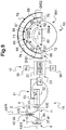
- the figure 1 presents an aircraft 1 of the hybrid rotorcraft type 1 according to the invention provided with a fuselage carrying at least one lift rotor 5 and a propulsion system 7.
- the propulsion system 7 includes at least one propulsion rotor 8, for example of the propeller type, comprising a plurality of first blades 9 having a first variable pitch at least or even only collectively for example.
- the hybrid rotorcraft 1 includes a first propellant propellant rotor and a second propeller propellant rotor arranged on either side of the fuselage 1, possibly at each outer end of a wing 3.
- the lift rotor 5 is provided with a plurality of second blades 6 having a second pitch variable collectively and cyclically for example.
- the aircraft 1 includes a power plant 2 provided with at least one engine 10, for example of the turboshaft type.
- the power plant 2 can comprise an interconnection system 11 including at least one power transmission box, at least one transmission shaft, etc.
- the speeds of rotation of the output shafts of the motors 10, of the propulsion rotors 8, of the lift rotor 5 and of the mechanical interconnection system 11 are optionally proportional to each other, the proportionality ratio being variable or constant whatever the configuration of flight of the hybrid rotorcraft 1 in normal operating conditions of the integrated driveline.
- each engine 10 operates according to an operating envelope comprising one or more of the aforementioned speeds, namely for example: a take-off speed defining a maximum take-off power PMD, a maximum continuous speed defining a maximum continuous power PMC, a speed transient defining a maximum transient power PMT, a first emergency regime defining a super emergency power PSU, a second emergency regime defining a maximum emergency power PMU and / or a third emergency regime defining an intermediate power emergency PIU.
- a take-off speed defining a maximum take-off power PMD
- a maximum continuous speed defining a maximum continuous power PMC
- a speed transient defining a maximum transient power PMT
- a first emergency regime defining a super emergency power PSU
- a second emergency regime defining a maximum emergency power PMU
- / or a third emergency regime defining an intermediate power emergency PIU.
- each pilot can have a TCC thrust control making it possible to collectively modify the first pitch of the first blades of each propulsion rotor 8, and for example an average pitch of the first blades 9 of the propulsion rotors 8.
- the TCC thrust control acts in an identical manner on the first steps of the first blades 9 in order to obtain a collective variation of the first pitch of the first blades 9.
- the pilot will require an increase of 5 degrees of the average pitch. of all of the first blades 9 of the propulsion rotors 8 to increase the resulting thrust generated in particular by the first propulsion rotor and the second propulsion rotor, the average pitch of the first blades 9 of the first and second propulsion rotors possibly being equal to the half sum of the pitches of the first blades 9 of the two propulsion rotors 8.
- the thrust control can transmit an order for example to at least one control computer AMC1, this control computer AMC1 controlling a kinematic chain 200 connected to the first blades 9 of the propulsion rotors 8.
- this control computer AMC1 controls at least a jack 201 disposed on said kinematic chain 200.
- the pilot can have a yaw control device provided with a yaw control means not shown, for example by controlling the pitches of the first blades 9 of the blades in a different manner.
- two propulsion rotors 8 For example, only the collective pitch of the first blades 9 of a propulsion rotor 8 is modified in order to act on the yaw behavior of the hybrid rotorcraft.
- the hybrid rotorcraft 1 is provided with the usual CYCL, COL control means to collectively and cyclically control the pitch of the second blades 6 of the lift rotor 5.
- the TCC thrust control is carried by a mobile COL pitch lever. in rotation about a control axis AX1 to collectively control the second pitch of the second blades 6.
- a cyclic control CYCL can cyclically control the second pitch of the second blades 6 of the lift rotor 5.
- the figure 3 illustrates a piloting handle 45 according to the invention.
- this piloting handle 45 can be arranged on the step lever COL illustrated above, on the cyclic control CYCL, on another type of vehicle, etc.
- the piloting handle 45 comprises a handle 46, possibly hollow.
- the handle 46 can be arranged on a tube of a lever for example.
- the pilot handle 45 is provided with an end housing 47 carried by the handle 46.
- This end box 47 comprises a hollow shell 48.
- the shell 48 is provided in particular with an upper face 51.
- the end box 47 comprises at least one control 52 operable by a pilot holding the piloting handle 45.
- Each control 52 projects from the upper face 51. towards an external environment EXT.
- each control 52 comprises a member extending outside the hull to be maneuverable by a pilot.
- each control 52 is movable relative to the shell 48.
- the upper face 51 extends at least one control 52 of the push-button type 521 and / or a control 52 of the push-button type. rocker 522 and / or a control 52 of lever type 523 and / or a control 52 of Chinese hat type 524.
- Each control can be connected to wire connections running through the handle.
- the piloting handle 45 has a controllable member 530 that can be requested by an individual to generate a signal, this signal being able to modify the behavior of at least one member such as the pitch of a blade or the position of a blade. pointer on a screen for example.
- the end box 47 comprises at least one electronic wall 56 carrying the controllable member.
- This electronic wall 56 integrates an electronic circuit 58, this electronic circuit 58 comprising at least one sensor cooperating with the controllable member to detect the operation of this controllable member and generate a signal as a function of this stress.
- the shell 48 defines a hollow internal volume INT.
- the internal volume INT is delimited in an elevation direction by a lower wall 481 and an upper wall 482 comprising the upper face, in a transverse direction and seen from above by a left wall 483 and a right wall 484, and d 'front to back by a front wall and a rear wall.
- the various walls of the shell 48 are formed by one or more elements.
- the lower wall 481 the left wall 483, the right wall 484, the front wall and the rear wall together form a container reversibly closed by the top wall 482.
- controllable member 530 may comprise a button movable relative to the end housing 47 and arranged at least partially outside said shell 48.
- the controllable member 530 may include a rotary button 53.
- This rotary button 53 is movable in rotation relative to the end housing 47 about an axis of rotation AX2.
- the piloting handle 45 is movable around a piloting axis AX1, for example by being arranged on a lever COL collectively controlling the second pitch of the second blades of a lift rotor 5, the axis of rotation AX2 can be parallel to the axis of piloting AX1.
- the rotary button 53 may have a wheel 54 arranged outside the shell 48, namely outside the internal volume INT.
- the rotary button 53 can also include a shaft 55 which is integral with the wheel 54 in rotation about the axis of rotation AX2.
- this shaft 55 is carried by the shell 48 and in particular by a side 57 of the shell 48 forming the electronic wall 56, for example a side 57 attached to the upper face 51.
- This side 57 forming the electronic wall 56 can for example be the left wall or the aforementioned right wall.
- the shaft 55 is also movable in rotation relative to the flank 57 about the axis of rotation AX2.
- a bearing is arranged between the shaft 55 and the sidewall 57.
- the wheel 54 rotates around the axis of rotation AX2 while rotating around a fixed shaft.
- the wheel 54 may have a diameter L1 which is maximized with respect to the shell 48 to be very accessible to a pilot's index finger.
- This diameter L1 can be established in order however to avoid friction, discomfort or unwanted control vis-à-vis the hand of a pilot.
- this shell 48 can extend longitudinally in a longitudinal direction D2 over a first length L2 and in elevation along a direction in elevation D3 over a second length L3, the first length L2 and / or the second length L3 being less than the diameter L1.
- controllable member 530 may include a button 5301 movable in translation.
- controllable member 530 may include a tactile face 5302 not only carried but also integrated into the electronic wall 56.
- the end box 47 therefore comprises an electronic wall 56 integrating an electronic circuit 58.
- Such a wall electronics 56 can be obtained by a plastronics method.
- the electronic circuit 58 is provided with at least one sensor cooperating, where appropriate, with the rotary button 53.
- the electronic circuit 58 generates at least one signal which varies when the controllable member is requested, and more precisely according to the example of the figure 4 when the wheel 54 is rotated around the axis of rotation AX2.
- a signal can be an analog or digital signal for example.
- the electronic circuit 58 can further include at least one electrically conductive track for example.
- the electronic circuit 58 can be connected to at least one electrical connection 61, 62.
- This electrical connection 61, 62 can be a wired connection running in or against the handle 46 and / or in or against the housing and / or integrated. by plastronics to at least one member of the handle and / or of the housing.
- the electronic circuit 58 comprises at least one pair of two dissimilar sensors 59, 60 each generating a signal varying as a function of the stress on the controllable member, and where appropriate for example by function of a rotation of the wheel 54 or of a translation of the button 5301 or of a pressure exerted on the tactile face 5302.
- the two sensors 59, 60 of the same pair can communicate with the same control computer AMC1.
- the two sensors of a pair respectively comprise a hall effect sensor 59 and a potentiometer 60.
- the electronic circuit 58 may include at least two said pairs 301, 302 of two sensors 59, 60, the two sensors 59, 60 of a pair 301 communicating with a first control computer AMC1 and the two sensors 59, 60 of the another pair 302 communicating with a second control computer AMC2.
- this hybrid rotorcraft 1 can be fitted with a piloting aid 15.
- the figure 7 presents such a piloting aid device 15.
- This piloting aid device 15 comprises an onboard computer 20.
- the piloting aid device 15 includes an indicator 65 controlled by the onboard computer 20 as well as possibly a plurality of sensors connected to the on-board computer 20.
- the on-board computer 20 can include one or more computers communicating together. According to the example shown, the on-board computer 20 comprises at least one central computer 22 and one usual engine computer 21 per engine, or even one or more of the aforementioned control computers. The central computer 22 can be merged with one of the aforementioned control computers.
- Such an engine computer 21 is for example of the type of a computer of a system known by the acronym FADEC. Each engine computer 21 is then connected to at least one engine sensor. Such an engine computer 21 can regulate a heat engine by controlling its fuel metering device, for example, or an electric motor. Such an engine computer 21 can also deliver, for each operating speed, the power margin available for this engine with respect to the maximum power at this speed and can deliver a value of a current power delivered by this engine.
- a single computer is for example employed.
- Each computer may for example comprise at least one processor 23, at least one memory 24, at least one circuit integrated, at least one programmable system, at least one logic circuit, these examples not limiting the scope given to the expression “computer”.
- the on-board computer 20 is connected by wired or wireless connections to sensors 31 for measuring monitoring parameters of each engine 10.
- each engine computer 21 is connected to a set of engine sensors.
- the monitoring parameters of an engine 10 can include at least one parameter to be chosen from a list including the speed of rotation Ng of a gas generator of each engine 10, the torque TQ of each engine 10 and a temperature of the gases by example the temperature of the gases T45 at the inlet of a low pressure free turbine of each engine 10.
- the piloting aid device 15 may have a sensor 32 for measuring the speed of rotation Ng of the engine, a torque meter 34 for measuring the torque TQ developed by the engine 10 on a motor output shaft 100 driven by this engine 10, and a sensor 33 for measuring the temperature of the gases T45 of the engine 10.
- a speed sensor motor rotation 40 can measure the rotational speed of the motor output shaft.
- the piloting aid device 15 may include a sensor 35 for the external pressure P0 and a sensor 36 for the external temperature T0 which are connected to the on-board computer 20, and for example to the central computer 22.
- the on-board computer 20, and for example the central computer 22, can be connected to a propulsion rotor torque meter 37 by propulsion rotor 8.
- Each propulsion rotor torque meter 37 can measure a torque on a propulsion rotor shaft 90 driving in rotation of the propellant rotor 8 around its axis of rotation AXH.
- a propellant rotor rotation speed sensor 41 can measure the rotational speed of the propellant rotor shaft 90.
- the on-board computer 20, and for example the central computer 22, can be connected to a rotor torque meter 38.
- the rotor torque meter 38 can measure a torque on a rotor shaft 500 rotating the lift rotor 5 around its axis of rotation AXR .
- a rotor rotational speed sensor 42 can measure the rotational speed of the rotor shaft 500.
- the on-board computer 20, and for example the central computer 22, can be connected to an average pitch sensor measuring the current average pitch of the first blades of the propulsion rotor 8 and / or to an air speed sensor able to measure the true air speed hybrid rotorcraft and / or a rotational speed sensor measuring the rotational speed of the propulsion rotors 8 and / or a rotational speed sensor measuring the rotational speed of the lift rotor 5 and / or a pitch sensor measuring the pitch collective of the second blades of the lift rotor 5.
- the on-board computer 20 is connected to an indicator 65 by customary links not shown.
- an indicator comprises a screen 651 and possibly a computer or even one of the aforementioned computers.
- the indicator 65 has a travel path 68 which extends from a first end 69 to a second end 70.
- the on-board computer 20 transmits a signal to the indicator 65.
- the indicator 65 positions a first pointer 66 on the travel path 68.
- the position of the first pointer 66 is calculated by the computer. 20 or indicator 65 and varies according to a first power P1 of power plant 2 consumed by the propulsion system 7.
- the indicator 65 positions a second pointer 67 on the travel path 68.
- the position of the second pointer 67 is calculated by the on-board computer 20 or the indicator 65 and varies as a function of a second power P2 of the. power plant 2 consumed by the lift rotor 5.
- first pointer 66 approaches along a first direction S1 of displacement of the second end 70 when the first power P1 increases.
- second pointer 67 approaches the first end 69 in a second direction S2 of movement when the second power P2 increases, the second direction S2 being opposite to the first direction S1.
- variable space 71 separates the first pointer 66 and the second pointer 67 as long as the power plant 2 has a power margin with respect to the maximum power associated with the current speed.
- a first distance DIS1 separating the first end 69 from the first pointer 66 is established to be the image of the first power P1, a second distance DIS2 separating the second end 70 from the second pointer 67 being the image of the second power. P2.
- the space 74 separating the first pointer 66 and the second pointer 67 extends over a third DIS3 representing an unused power margin of the power plant 2 at current speed as long as the first pointer 66 is arranged between the power plant 2.
- the fourth distance DIS4 corresponding to the sum of the first distance DIS1, of the second distance DIS 2 and the third distance DIS 3 is the image of the maximum power available at the current speed.
- the indicator 65 gives a first zone Z1 situated between the first end 69 and the first pointer 66 a first visually identifiable background to facilitate reading of the information.
- the indicator 65 can give a second zone Z2 situated between the second end 70 and the second pointer 67 a second background that is visually identifiable and possibly different from the first background.
- the first zone Z1 and the second zone Z2 comprise hatching and / or different colors.
- the on-board computer 20 determines the values of the first power P1 and of the second power P2 and transmits these values as well as the maximum power to the indicator 65.
- the indicator 65 determines a target position in the indicator 65 of the first pointer 66 as a function of the first power P1 and a target position of the second pointer 67 as a function of said second power P2 according to at least one stored law.
- the maximum power can be taken into account.
- the first distance DIS1 is calculated as a function of the product of a constant and a quotient of the first power P1 and of the maximum power
- the second distance DIS2 being calculated as a function of the product of said constant and d 'a quotient of the second power P2 and the maximum power.
- the on-board computer 20 can calculate the first power P1 using the sum of the power consumed by each propulsion rotor.
- This power consumed by each propulsion rotor can be obtained by multiplying the propulsion rotor torque 8 exerted on the propulsion rotor shaft 90 and the speed of rotation of the propulsion rotor shaft 90 which are measured respectively with the propellant rotor torque meter 37 and the propellant rotor rotation speed sensor 41.
- the on-board computer 20 calculates the power consumed by each propulsion rotor 8 using stored polars and parameters of the rotor propellant 8 such as the radius of the second blades, the end speed of the first blades of the propulsion rotor, the air speed of the aircraft, the pitch of the second blades, etc.
- the on-board computer 20 can calculate the second power P2 consumed by the lift rotor by multiplying the torque exerted on the rotor shaft 500 and the speed of rotation of the rotor shaft 500 which are measured respectively with the rotor torque meter 38 and the rotor rotation speed sensor 42.
- the on-board computer 20 determines the values of a first collective pitch current of the first blades 9 and of a second collective pitch current of the second blades 6.
- the indicator 65 determines a target position in the indicator 65 of the first pointer 66 as a function of the first current collective step and a target position of the second pointer 67 as a function of the second current collective step.
- each pointer can illustrate a collective step expressed in power.
- the first pointer 66 can also point to an air speed scale 75 of the hybrid rotorcraft 1.
- the first pointer moves in parallel with graduations 76 each relating to an air speed.
- the on-board computer can calculate at least a first limit of pitch 85 of the first blades 9, possibly via a conversion into a power equivalent, and transmitting a signal to the indicator carrying this first step limit.
- the indicator calculates the location of a symbol representing the first step limit 85 along the travel path and displays this symbol illustrating the first step limit 85 along the travel path 68.
- the on-board computer 20 can calculate at least one second pitch limit 86 of the second blades 6, possibly via a conversion into power equivalent, and transmit a signal to the indicator carrying this second pitch limit 86.
- the indicator calculates the location of a symbol representing the second step limit 86 along the travel path and displays this symbol illustrating the second step limit 86 along the travel path 68.
- the displacement path 68 may have the shape of a first circular arc 72.
- the air speed scale 75 is positioned on a second circular arc 77 contiguous to the first circular arc 72, for example at above the first circular arc 72.
- the first circular arc 72 can be located above an artificial horizon 80 and / or a heading 81.
- the first pointer 66 and the second pointer 67 may be movable linearly, for example along a direction 78 superimposed on an air speed scale 75 of the hybrid rotorcraft 1, said one air speed scale 75 being provided with graduations 76.
Landscapes
- Engineering & Computer Science (AREA)
- Aviation & Aerospace Engineering (AREA)
- Mechanical Engineering (AREA)
- Automation & Control Theory (AREA)
- Toys (AREA)
- Automatic Cycles, And Cycles In General (AREA)
Applications Claiming Priority (1)
| Application Number | Priority Date | Filing Date | Title |
|---|---|---|---|
| FR1906677A FR3097530B1 (fr) | 2019-06-20 | 2019-06-20 | Poignée de pilotage et giravion hybride muni d’un rotor de sustentation et d’au moins un rotor propulsif à hélice générant une poussée |
Publications (2)
| Publication Number | Publication Date |
|---|---|
| EP3753844A1 true EP3753844A1 (de) | 2020-12-23 |
| EP3753844B1 EP3753844B1 (de) | 2023-07-19 |
Family
ID=68581889
Family Applications (1)
| Application Number | Title | Priority Date | Filing Date |
|---|---|---|---|
| EP20176315.8A Active EP3753844B1 (de) | 2019-06-20 | 2020-05-25 | Steuerknüppel und hybrid-drehflügelflugzeug, das mit einem auftriebsrotor und mindestens einem schub erzeugenden propellervortriebsrotor ausgestattet ist |
Country Status (3)
| Country | Link |
|---|---|
| US (1) | US11572163B2 (de) |
| EP (1) | EP3753844B1 (de) |
| FR (1) | FR3097530B1 (de) |
Cited By (1)
| Publication number | Priority date | Publication date | Assignee | Title |
|---|---|---|---|---|
| US20220411089A1 (en) * | 2021-06-29 | 2022-12-29 | Beta Air, Llc | Electric aircraft for generating a yaw force |
Families Citing this family (2)
| Publication number | Priority date | Publication date | Assignee | Title |
|---|---|---|---|---|
| FR3097527B1 (fr) * | 2019-06-20 | 2021-06-18 | Airbus Helicopters | Procédé d’aide au pilotage d’un giravion hybride muni d’un rotor de sustentation et d’au moins un rotor propulsif à hélice générant une poussée |
| FR3124165A1 (fr) * | 2021-06-17 | 2022-12-23 | Airbus Helicopters | Procédé et dispositif d’aide au pilotage d’un giravion muni d’au moins une hélice |
Citations (9)
| Publication number | Priority date | Publication date | Assignee | Title |
|---|---|---|---|---|
| US4488851A (en) | 1982-04-01 | 1984-12-18 | The United States Of America As Represented By The Secretary Of The Army | Power management system |
| FR2946322A1 (fr) | 2009-06-04 | 2010-12-10 | Eurocopter France | Dispositif d'aide au pilotage d'un helicoptere hybride, helicoptere hybride muni d'un tel dispositif et procede mis en oeuvre par ledit dispositif |
| WO2016043942A2 (en) | 2014-08-28 | 2016-03-24 | Sikorsky Aircraft Corporation | Pitch control system |
| WO2016043943A2 (en) | 2014-08-28 | 2016-03-24 | Sikorsky Aircraft Corporation | Pitch control system |
| FR3041783A1 (fr) | 2015-09-24 | 2017-03-31 | Dav | Interface de commande a retour haptique |
| US9650125B2 (en) | 2013-12-18 | 2017-05-16 | Merlin Technology, Inc. | Control interface, system and method |
| US20170147106A1 (en) | 2015-11-19 | 2017-05-25 | Hyundai Motor Company | Touch input device, vehicle including the same, and method of manufacturing the vehicle |
| US20180099739A1 (en) | 2016-10-12 | 2018-04-12 | Airbus Helicopters | Electric control member, a rotary wing aircraft, and a method |
| US20190112071A1 (en) | 2017-10-17 | 2019-04-18 | Sikorsky Aircraft Corporation | Composite airspeed indicator display for compound aircrafts |
Family Cites Families (7)
| Publication number | Priority date | Publication date | Assignee | Title |
|---|---|---|---|---|
| US2787746A (en) * | 1954-07-23 | 1957-04-02 | Chance Vought Aircraft Inc | Auxiliary servo control hand grip for a manually operable control lever |
| US4716399A (en) * | 1985-01-14 | 1987-12-29 | The Boeing Company | Optomechanical control apparatus |
| BRPI0706613A2 (pt) * | 2006-01-17 | 2011-04-05 | Gulfstream Aerospace Corp | aparelho e método para controle de backup em um sistema de controle de vÈo distribuìdo |
| US7518070B2 (en) * | 2007-02-07 | 2009-04-14 | Lear Corporation | Electrical switch |
| FR3038882B1 (fr) * | 2015-07-16 | 2018-03-23 | Airbus Helicopters | Aeronef combine muni d'un dispositif anticouple complementaire |
| US10353510B2 (en) * | 2016-08-26 | 2019-07-16 | Motorola Solutions, Inc. | Force-scalable stationary interface control |
| US10011348B1 (en) * | 2017-05-02 | 2018-07-03 | Kitty Hawk Corporation | Vertical thrust lever |
-
2019
- 2019-06-20 FR FR1906677A patent/FR3097530B1/fr active Active
-
2020
- 2020-05-25 EP EP20176315.8A patent/EP3753844B1/de active Active
- 2020-06-16 US US16/903,047 patent/US11572163B2/en active Active
Patent Citations (12)
| Publication number | Priority date | Publication date | Assignee | Title |
|---|---|---|---|---|
| US4488851A (en) | 1982-04-01 | 1984-12-18 | The United States Of America As Represented By The Secretary Of The Army | Power management system |
| FR2946322A1 (fr) | 2009-06-04 | 2010-12-10 | Eurocopter France | Dispositif d'aide au pilotage d'un helicoptere hybride, helicoptere hybride muni d'un tel dispositif et procede mis en oeuvre par ledit dispositif |
| US9650125B2 (en) | 2013-12-18 | 2017-05-16 | Merlin Technology, Inc. | Control interface, system and method |
| WO2016043942A2 (en) | 2014-08-28 | 2016-03-24 | Sikorsky Aircraft Corporation | Pitch control system |
| WO2016043943A2 (en) | 2014-08-28 | 2016-03-24 | Sikorsky Aircraft Corporation | Pitch control system |
| FR3041783A1 (fr) | 2015-09-24 | 2017-03-31 | Dav | Interface de commande a retour haptique |
| US20170147106A1 (en) | 2015-11-19 | 2017-05-25 | Hyundai Motor Company | Touch input device, vehicle including the same, and method of manufacturing the vehicle |
| US20180099739A1 (en) | 2016-10-12 | 2018-04-12 | Airbus Helicopters | Electric control member, a rotary wing aircraft, and a method |
| FR3057243A1 (fr) | 2016-10-12 | 2018-04-13 | Airbus Helicopters | Organe de commande electrique, aeronef a voilure tournante et procede |
| EP3309061A1 (de) | 2016-10-12 | 2018-04-18 | Airbus Helicopters | Elektrisches steuerorgan, drehflügelflugzeug und verfahren |
| US20190112071A1 (en) | 2017-10-17 | 2019-04-18 | Sikorsky Aircraft Corporation | Composite airspeed indicator display for compound aircrafts |
| US20190113403A1 (en) | 2017-10-17 | 2019-04-18 | Sikorsky Aircraft Corporation | Composite airspeed indicator display for compound aircrafts |
Cited By (2)
| Publication number | Priority date | Publication date | Assignee | Title |
|---|---|---|---|---|
| US20220411089A1 (en) * | 2021-06-29 | 2022-12-29 | Beta Air, Llc | Electric aircraft for generating a yaw force |
| US11745886B2 (en) * | 2021-06-29 | 2023-09-05 | Beta Air, Llc | Electric aircraft for generating a yaw force |
Also Published As
| Publication number | Publication date |
|---|---|
| US11572163B2 (en) | 2023-02-07 |
| US20200398980A1 (en) | 2020-12-24 |
| FR3097530A1 (fr) | 2020-12-25 |
| EP3753844B1 (de) | 2023-07-19 |
| FR3097530B1 (fr) | 2022-09-02 |
Similar Documents
| Publication | Publication Date | Title |
|---|---|---|
| EP3753844B1 (de) | Steuerknüppel und hybrid-drehflügelflugzeug, das mit einem auftriebsrotor und mindestens einem schub erzeugenden propellervortriebsrotor ausgestattet ist | |
| EP2505502B1 (de) | Verfahren, Vorrichtung zur Unterstützung der Steuerung eines Luftfahrzeugs, und Luftfahrzeug | |
| FR3097527A1 (fr) | Procédé d’aide au pilotage d’un giravion hybride muni d’un rotor de sustentation et d’au moins un rotor propulsif à hélice générant une poussée | |
| EP2258615B1 (de) | Hilfsvorrichtung zum Steuern eines hybriden Hubschraubers, hybrider Hubschrauber mit einer solchen Vorrichtung, sowie Verfahren zum Betrieb einer solchen Vorrichtung | |
| EP3064437B1 (de) | Verfahren und vorrichtung zur bestimmung und optimierung von kennwerten der betriebsfunktion eines drehflügelflugzeugs | |
| EP3702269B1 (de) | Haptischer warnmechanismus zur warnung eines piloten eines flugzeugs und flugzeug | |
| EP3309061B1 (de) | Elektrisches steuerorgan, drehflügelflugzeug und verfahren | |
| WO2006075096A1 (fr) | Dispositif d'orientation de la tete de rotor pour helicoptere | |
| FR2943316A1 (fr) | Procede d'uniformisation de la commande de poussee des moteurs d'un aeronef | |
| EP3147212B1 (de) | Vorrichtung zur regelung der drehzahl des rotors eines drehflügelflugzeugs, mit einer solchen vorrichtung ausgestattetes drehflügelflugzeug und entsprechende regelungsmethode | |
| EP3251955B1 (de) | Verfahren und hilfsvorrichtung zur steuerung eines luftfahrzeugs, und luftfahrzeug | |
| EP3647192B1 (de) | Pilotenassistenzverfahren und -vorrichtung eines hybrid-drehflügelflugzeugs, das mit einem auftriebsrotor und mindestens einem schuberzeugenden vortriebsrotor ausgestattet ist | |
| FR2871520A1 (fr) | Indicateur de pilotage permettant de predire l'evolution des parametres de surveillance d'un turbomoteur | |
| EP3060929B1 (de) | Verfahren und vorrichtung zur messung des winkels eines angriffs und des schiebewinkels eines flugzeugs | |
| EP3882132B1 (de) | Verfahren zum schutz des drehmomentes und/oder schubes von propellern eines hybridhubschraubers und hybridhubschrauber | |
| CA3158841A1 (fr) | Procede d'aide au pilotage d'un giravion en hautes altitudes grace a l'apport d'une puissance mecanique provenant d'une installation motrice electrique | |
| EP2527660B1 (de) | Verfahren zur Bestimmung der statischen Kraft, die von einer Servosteuerung entwickelt wird | |
| EP4063261B1 (de) | System zum steuern mindestens eines propellers eines hybrid-drehflügelflugzeugs, hybrid-drehflügelflugzeug und entsprechendes steuerungsverfahren | |
| CA3102691A1 (fr) | Dispositif de surveillance d'une marge de poussee pour giravion, giravion associe et procede correspondant | |
| EP3868658B1 (de) | Verfahren zur steuerung eines hybrid-helikopters im falle eines ausfalls einer antriebsanlage | |
| EP4183673A1 (de) | System zur steuerung des antriebs eines hybridangetriebenen schiffes |
Legal Events
| Date | Code | Title | Description |
|---|---|---|---|
| PUAI | Public reference made under article 153(3) epc to a published international application that has entered the european phase |
Free format text: ORIGINAL CODE: 0009012 |
|
| STAA | Information on the status of an ep patent application or granted ep patent |
Free format text: STATUS: THE APPLICATION HAS BEEN PUBLISHED |
|
| AK | Designated contracting states |
Kind code of ref document: A1 Designated state(s): AL AT BE BG CH CY CZ DE DK EE ES FI FR GB GR HR HU IE IS IT LI LT LU LV MC MK MT NL NO PL PT RO RS SE SI SK SM TR |
|
| AX | Request for extension of the european patent |
Extension state: BA ME |
|
| STAA | Information on the status of an ep patent application or granted ep patent |
Free format text: STATUS: REQUEST FOR EXAMINATION WAS MADE |
|
| 17P | Request for examination filed |
Effective date: 20210122 |
|
| RBV | Designated contracting states (corrected) |
Designated state(s): AL AT BE BG CH CY CZ DE DK EE ES FI FR GB GR HR HU IE IS IT LI LT LU LV MC MK MT NL NO PL PT RO RS SE SI SK SM TR |
|
| STAA | Information on the status of an ep patent application or granted ep patent |
Free format text: STATUS: EXAMINATION IS IN PROGRESS |
|
| 17Q | First examination report despatched |
Effective date: 20220211 |
|
| GRAP | Despatch of communication of intention to grant a patent |
Free format text: ORIGINAL CODE: EPIDOSNIGR1 |
|
| STAA | Information on the status of an ep patent application or granted ep patent |
Free format text: STATUS: GRANT OF PATENT IS INTENDED |
|
| RIC1 | Information provided on ipc code assigned before grant |
Ipc: B64C 27/82 20060101ALN20230208BHEP Ipc: B64C 27/22 20060101ALI20230208BHEP Ipc: B64C 13/04 20060101AFI20230208BHEP |
|
| RIC1 | Information provided on ipc code assigned before grant |
Ipc: B64C 27/82 20060101ALN20230214BHEP Ipc: B64C 27/22 20060101ALI20230214BHEP Ipc: B64C 13/04 20060101AFI20230214BHEP |
|
| INTG | Intention to grant announced |
Effective date: 20230309 |
|
| GRAS | Grant fee paid |
Free format text: ORIGINAL CODE: EPIDOSNIGR3 |
|
| GRAA | (expected) grant |
Free format text: ORIGINAL CODE: 0009210 |
|
| STAA | Information on the status of an ep patent application or granted ep patent |
Free format text: STATUS: THE PATENT HAS BEEN GRANTED |
|
| P01 | Opt-out of the competence of the unified patent court (upc) registered |
Effective date: 20230530 |
|
| AK | Designated contracting states |
Kind code of ref document: B1 Designated state(s): AL AT BE BG CH CY CZ DE DK EE ES FI FR GB GR HR HU IE IS IT LI LT LU LV MC MK MT NL NO PL PT RO RS SE SI SK SM TR |
|
| REG | Reference to a national code |
Ref country code: GB Ref legal event code: FG4D Free format text: NOT ENGLISH |
|
| REG | Reference to a national code |
Ref country code: CH Ref legal event code: EP |
|
| REG | Reference to a national code |
Ref country code: DE Ref legal event code: R096 Ref document number: 602020013945 Country of ref document: DE |
|
| REG | Reference to a national code |
Ref country code: IE Ref legal event code: FG4D Free format text: LANGUAGE OF EP DOCUMENT: FRENCH |
|
| REG | Reference to a national code |
Ref country code: LT Ref legal event code: MG9D |
|
| REG | Reference to a national code |
Ref country code: NL Ref legal event code: MP Effective date: 20230719 |
|
| REG | Reference to a national code |
Ref country code: AT Ref legal event code: MK05 Ref document number: 1589224 Country of ref document: AT Kind code of ref document: T Effective date: 20230719 |
|
| PG25 | Lapsed in a contracting state [announced via postgrant information from national office to epo] |
Ref country code: NL Free format text: LAPSE BECAUSE OF FAILURE TO SUBMIT A TRANSLATION OF THE DESCRIPTION OR TO PAY THE FEE WITHIN THE PRESCRIBED TIME-LIMIT Effective date: 20230719 |
|
| PG25 | Lapsed in a contracting state [announced via postgrant information from national office to epo] |
Ref country code: GR Free format text: LAPSE BECAUSE OF FAILURE TO SUBMIT A TRANSLATION OF THE DESCRIPTION OR TO PAY THE FEE WITHIN THE PRESCRIBED TIME-LIMIT Effective date: 20231020 |
|
| PG25 | Lapsed in a contracting state [announced via postgrant information from national office to epo] |
Ref country code: IS Free format text: LAPSE BECAUSE OF FAILURE TO SUBMIT A TRANSLATION OF THE DESCRIPTION OR TO PAY THE FEE WITHIN THE PRESCRIBED TIME-LIMIT Effective date: 20231119 |
|
| PG25 | Lapsed in a contracting state [announced via postgrant information from national office to epo] |
Ref country code: SE Free format text: LAPSE BECAUSE OF FAILURE TO SUBMIT A TRANSLATION OF THE DESCRIPTION OR TO PAY THE FEE WITHIN THE PRESCRIBED TIME-LIMIT Effective date: 20230719 Ref country code: RS Free format text: LAPSE BECAUSE OF FAILURE TO SUBMIT A TRANSLATION OF THE DESCRIPTION OR TO PAY THE FEE WITHIN THE PRESCRIBED TIME-LIMIT Effective date: 20230719 Ref country code: PT Free format text: LAPSE BECAUSE OF FAILURE TO SUBMIT A TRANSLATION OF THE DESCRIPTION OR TO PAY THE FEE WITHIN THE PRESCRIBED TIME-LIMIT Effective date: 20231120 Ref country code: NO Free format text: LAPSE BECAUSE OF FAILURE TO SUBMIT A TRANSLATION OF THE DESCRIPTION OR TO PAY THE FEE WITHIN THE PRESCRIBED TIME-LIMIT Effective date: 20231019 Ref country code: LV Free format text: LAPSE BECAUSE OF FAILURE TO SUBMIT A TRANSLATION OF THE DESCRIPTION OR TO PAY THE FEE WITHIN THE PRESCRIBED TIME-LIMIT Effective date: 20230719 Ref country code: LT Free format text: LAPSE BECAUSE OF FAILURE TO SUBMIT A TRANSLATION OF THE DESCRIPTION OR TO PAY THE FEE WITHIN THE PRESCRIBED TIME-LIMIT Effective date: 20230719 Ref country code: IS Free format text: LAPSE BECAUSE OF FAILURE TO SUBMIT A TRANSLATION OF THE DESCRIPTION OR TO PAY THE FEE WITHIN THE PRESCRIBED TIME-LIMIT Effective date: 20231119 Ref country code: HR Free format text: LAPSE BECAUSE OF FAILURE TO SUBMIT A TRANSLATION OF THE DESCRIPTION OR TO PAY THE FEE WITHIN THE PRESCRIBED TIME-LIMIT Effective date: 20230719 Ref country code: GR Free format text: LAPSE BECAUSE OF FAILURE TO SUBMIT A TRANSLATION OF THE DESCRIPTION OR TO PAY THE FEE WITHIN THE PRESCRIBED TIME-LIMIT Effective date: 20231020 Ref country code: FI Free format text: LAPSE BECAUSE OF FAILURE TO SUBMIT A TRANSLATION OF THE DESCRIPTION OR TO PAY THE FEE WITHIN THE PRESCRIBED TIME-LIMIT Effective date: 20230719 Ref country code: AT Free format text: LAPSE BECAUSE OF FAILURE TO SUBMIT A TRANSLATION OF THE DESCRIPTION OR TO PAY THE FEE WITHIN THE PRESCRIBED TIME-LIMIT Effective date: 20230719 |
|
| PG25 | Lapsed in a contracting state [announced via postgrant information from national office to epo] |
Ref country code: PL Free format text: LAPSE BECAUSE OF FAILURE TO SUBMIT A TRANSLATION OF THE DESCRIPTION OR TO PAY THE FEE WITHIN THE PRESCRIBED TIME-LIMIT Effective date: 20230719 |