EP2527660B1 - Verfahren zur Bestimmung der statischen Kraft, die von einer Servosteuerung entwickelt wird - Google Patents
Verfahren zur Bestimmung der statischen Kraft, die von einer Servosteuerung entwickelt wird Download PDFInfo
- Publication number
- EP2527660B1 EP2527660B1 EP12003792.4A EP12003792A EP2527660B1 EP 2527660 B1 EP2527660 B1 EP 2527660B1 EP 12003792 A EP12003792 A EP 12003792A EP 2527660 B1 EP2527660 B1 EP 2527660B1
- Authority
- EP
- European Patent Office
- Prior art keywords
- max
- hydraulic distributor
- static force
- travel speed
- determined
- Prior art date
- Legal status (The legal status is an assumption and is not a legal conclusion. Google has not performed a legal analysis and makes no representation as to the accuracy of the status listed.)
- Active
Links
Images

Classifications
-
- B—PERFORMING OPERATIONS; TRANSPORTING
- B64—AIRCRAFT; AVIATION; COSMONAUTICS
- B64C—AEROPLANES; HELICOPTERS
- B64C13/00—Control systems or transmitting systems for actuating flying-control surfaces, lift-increasing flaps, air brakes, or spoilers
- B64C13/24—Transmitting means
- B64C13/38—Transmitting means with power amplification
- B64C13/40—Transmitting means with power amplification using fluid pressure
-
- F—MECHANICAL ENGINEERING; LIGHTING; HEATING; WEAPONS; BLASTING
- F15—FLUID-PRESSURE ACTUATORS; HYDRAULICS OR PNEUMATICS IN GENERAL
- F15B—SYSTEMS ACTING BY MEANS OF FLUIDS IN GENERAL; FLUID-PRESSURE ACTUATORS, e.g. SERVOMOTORS; DETAILS OF FLUID-PRESSURE SYSTEMS, NOT OTHERWISE PROVIDED FOR
- F15B15/00—Fluid-actuated devices for displacing a member from one position to another; Gearing associated therewith
- F15B15/20—Other details, e.g. assembly with regulating devices
- F15B15/28—Means for indicating the position, e.g. end of stroke
- F15B15/2815—Position sensing, i.e. means for continuous measurement of position, e.g. LVDT
-
- F—MECHANICAL ENGINEERING; LIGHTING; HEATING; WEAPONS; BLASTING
- F15—FLUID-PRESSURE ACTUATORS; HYDRAULICS OR PNEUMATICS IN GENERAL
- F15B—SYSTEMS ACTING BY MEANS OF FLUIDS IN GENERAL; FLUID-PRESSURE ACTUATORS, e.g. SERVOMOTORS; DETAILS OF FLUID-PRESSURE SYSTEMS, NOT OTHERWISE PROVIDED FOR
- F15B20/00—Safety arrangements for fluid actuator systems; Applications of safety devices in fluid actuator systems; Emergency measures for fluid actuator systems
- F15B20/007—Overload
-
- G—PHYSICS
- G01—MEASURING; TESTING
- G01L—MEASURING FORCE, STRESS, TORQUE, WORK, MECHANICAL POWER, MECHANICAL EFFICIENCY, OR FLUID PRESSURE
- G01L1/00—Measuring force or stress, in general
- G01L1/02—Measuring force or stress, in general by hydraulic or pneumatic means
-
- F—MECHANICAL ENGINEERING; LIGHTING; HEATING; WEAPONS; BLASTING
- F15—FLUID-PRESSURE ACTUATORS; HYDRAULICS OR PNEUMATICS IN GENERAL
- F15B—SYSTEMS ACTING BY MEANS OF FLUIDS IN GENERAL; FLUID-PRESSURE ACTUATORS, e.g. SERVOMOTORS; DETAILS OF FLUID-PRESSURE SYSTEMS, NOT OTHERWISE PROVIDED FOR
- F15B2211/00—Circuits for servomotor systems
- F15B2211/60—Circuit components or control therefor
- F15B2211/63—Electronic controllers
- F15B2211/6303—Electronic controllers using input signals
- F15B2211/6336—Electronic controllers using input signals representing a state of the output member, e.g. position, speed or acceleration
Definitions
- the present invention relates to a method for determining the static force developed by a servocontrol.
- an aircraft comprises actuators maneuverable by a pilot, such as the blades of a lift rotor of a helicopter-type rotorcraft or the rudders of an airplane for example.
- the kinematic chain connecting a flight control to an operating member is often provided with a hydraulic system comprising a servo control allowing the pilot to steer the aircraft without difficulty and with precision.
- a helicopter is provided with a main rotor ensuring its lift and propulsion.
- a pilot changes the pitch of the main rotor blades, that is to say their incidence relative to the incident airflow.
- the rotorcraft comprises a set of cyclic trays provided with a lower non-rotating plate and a rotating upper plate, this assembly being sometimes more simply called "swashplate".
- the lower non-rotating plate is connected to the flight controls of the pilot, generally by three separate control lines while the upper rotating plate is connected to each blade respectively by a connecting rod.
- the swash plate thus slides along the main rotor mast to control the general pitch of the main rotor blades while being able to oscillate in all directions around a ball joint to control the cyclic pitch of the blades.
- Oscillations and the vertical displacement of the swashplate, controlled by the pilot, are therefore at the origin of the variation of the pitch of the blades allowing the pilot to steer the helicopter.
- the pilot controls the swashplate via mechanical controls linked to this swashplate by connecting rods.
- the efforts to be made by the pilot to maneuver the swashplate are very important, especially if the mass of the rotorcraft is also important.
- a servo control of a hydraulic system is then arranged between an upstream portion and a downstream portion of each drive kinematic chain.
- the pilot then solicits the servo drives without special efforts via the upstream portion, then these servocontrols transcribe the order of the pilot and act on the downstream portion of the driveline.
- a helicopter is provided with a rear rotor whose pitch of the blades can be modified via a servo.
- the servocontrols comprise a jack provided with at least one cylindrical external body in which a sliding element with a power rod equipped with a control piston is translated.
- This control piston defines a retraction chamber and an expansion chamber inside this outer body.
- the servo control comprises a hydraulic distributor supplying fluid to the retraction chamber or the expansion chamber according to the order received.
- the displacement of the control piston of the sliding element relative to the outer body is then controlled by the hydraulic distributor which is actuated by the flight controls of the pilot of the helicopter, through the upstream portion of a kinematic chain.
- the hydraulic distributor supplies the retraction chamber or the expansion chamber with hydraulic fluid to require retraction or extension of the servocontrol.
- retract chamber a chamber causing the retraction of the servo control when said chamber is filled with a fluid.
- an “expansion chamber” is a chamber causing the extension of the servocontrol when said chamber is filled with a fluid.
- the servo control may further comprise a servo device, possibly integrated with the hydraulic distributor.
- the power rod is fixed on a fixed point of the aircraft belonging for example to a power transmission box, the body moving according to the orders received and being connected to the downstream portion of the drive train.
- the person skilled in the art denominates this type of servocontrol according to the expression "servocontrol with moving body”.
- the body is fixed to a fixed point of the aircraft, the power rod moving according to the orders received and being connected to the downstream portion of the kinematic chain.
- the skilled person thus denominates this type of servo control according to the expression "servocontrol with fixed body”.
- a single-body servocontrol is then provided with a jack provided with a body defining a single internal space delimiting a retraction chamber and an expansion chamber separated by a control piston.
- the retraction chamber and the expansion chamber are then fed by a hydraulic distributor provided with a single hydraulic unit.
- This servo perfectly fulfills its function. However, for safety reasons, the skilled person tends, from a certain level of effort to develop, to use a servocontrol at least double body.
- a double-body servo control then comprises a jack provided with a lower body and an upper body assembled in tandem or parallel.
- a tandem double body servo control includes a sliding element with a power rod carrying two pistons, each piston delimiting in each body a retraction chamber and an expansion chamber.
- two hydraulic units of the hydraulic distributor actuated by a common control lever connected to the controls of the driver, respectively feed the retraction chambers and extension of the lower and upper bodies.
- a limit static force detection device on a servocontrol.
- the static force exerted on the servocontrol reaches a threshold limit, namely a static traction force or a static compression force
- the limit static force detection device triggers an alert to inform the pilot.
- the limit static force detection device comprises a detection element provided with a rod equipped with a detection piston sliding in a detection space, this detection space comprising two detection chambers delimited by the detection piston , independent of the retraction and extension chambers of the external body.
- the first detection chamber is supplied with fluid by the hydraulic circuit of the aircraft, the second detection chamber opening onto the outside of the servocontrol.
- the rod of the detection element protrudes from the body of the servo control to be connected to the downstream portion of the kinematic chain for example.
- This projecting portion of the detection element further comprises a lever adapted to cooperate with a push-button switch.
- the pressure in the sensing chamber keeps the sensing piston in high abutment so as to move its lever away from the switch.
- the threshold is reached, the pressure prevailing in the detection chamber no longer makes it possible to keep the detection piston in high abutment.
- the detection piston thus reaches a low stop, the lever then actuating the switch.
- the detection piston In order to prevent a passage of the fluid from the first detection chamber to the outside of the servocontrol, the detection piston has a seal. Since this seal is dynamically stressed, leakage towards the outside of the servocontrol may appear and lead to maintenance actions.
- the limit static force detection device is subjected to the forces experienced by the servo control being connected to the drive kinematic chain. Therefore, it is sized to support these efforts. This results in a significant financial cost and mass.
- the sliding of the detection piston in fact induces a game in the control kinematic chain in the event of a pressure drop in the hydraulic circuit supplying fluid to the limit static force detection device.
- a servocontrol provided with at least one limit force detection device.
- This device comprises a housing integral with a body of the servocontrol, the housing delimiting a detection space.
- a movable member shares this detection space in a first detection chamber opening on an internal space of said body and in a second detection chamber.
- the device has a means for detecting the position of the movable member in the detection space.
- the state of the art further includes the document WO 2008/095525 , the document US 2004/0128868 and the document US 2010/0294125
- the present invention therefore has the particular object of proposing an alternative method and servocontrol enabling in particular to overcome the aforementioned limitations.
- the servocontrol may be a servocontrol comprising a body or a plurality of bodies.
- the hydraulic distributor having an opening of variable section to feed a chamber of the internal space, the maximum displacement speed Vmax corresponds to the speed of movement of the sliding element in the absence of a static force applied to the servocontrol.
- the maximum displacement speed Vmax may be a constant, or even be considered as a variable depending on the current section of the variable section or even the temperature of the fluid. It is understood that the term "current section”, the value of the variable section at each moment, namely in real time.
- This method may comprise in addition one or more of the additional characteristics which follow.
- said current displacement speed V is determined in real time by determining a flow rate of said fluid by means of a means for measuring the usual flow rate, and then by dividing said flow rate by the surface of a constant section of the piston.
- the flow rate can be the flow rate of the fluid through the hydraulic distributor.
- the maximum displacement speed may alternatively be a constant predetermined by the manufacturer, possibly corresponding to the maximum speed of displacement of the sliding element when the opening of the hydraulic distributor supplying the cylinder is maximum and at a maximum temperature the range of use of the fluid envisaged.
- the hydraulic distributor communicating with the internal space by a variable section opening, this hydraulic distributor comprising a movable restriction means for adjusting the variable section, it is possible to determine a current value of the variable section of the hydraulic distributor.
- V max VS q * S 1 * 2 ⁇ * P in - P out S 0 .
- C q represents a predetermined pressure drop coefficient of the hydraulic distributor
- S 1 represents the current value of the variable section
- ⁇ represents the density of the fluid supplying the servocontrol
- P in represents the pressure supplying the fluid entering the hydraulic distributor
- P out represents the outlet pressure of the fluid leaving the hydraulic distributor
- S 0 represents the surface of a constant section of the piston
- * represents the sign of the multiplication.
- outlet pressure represents the pressure of the fluid leaving the hydraulic distributor, ie the pressure of the fluid present in a chamber of the internal space supplied by the hydraulic distributor.
- the pressure drop coefficient C q corresponds to the pressure drop of the hydraulic distributor between the inlet and the outlet of this hydraulic distributor, this coefficient being established by tests and which can be variable depending on the temperature of the fluid, for example.
- the density of the fluid may be a predetermined constant, or a variable established according to said fluid temperature.
- a processor of a computer executes, for example, instructions for determining the current value of the variable section, by using a position or movement sensor of the restriction means or even of a control lever of the hydraulic distributor, for example . Since the current section of the opening of the hydraulic distributor depends directly on the position of the restriction means, the calculator can easily determine this current section.
- the computer then deduces the maximum movement speed and the static force exerted on the servocontrol.
- outlet pressure of the hydraulic distributor can be established from the inlet pressure of the hydraulic distributor, possibly using an equation called "pressure equation” for convenience.
- the outlet pressure is proportional to the inlet pressure, the proportionality ratio being determined by tests by example.
- the outlet pressure is equal to half of the inlet pressure.
- the pressure drop coefficient and the density may be predetermined constants.
- a calculator can determine the coefficient of pressure loss and this density using databases, stored curves, or equations providing this coefficient of pressure loss and density according to said temperature.
- an alert is triggered when the static force exceeds a predetermined threshold.
- the computer triggers an audible or visual type alert. It is understood that it is possible to perform other post-treatments following the determination of the static force.
- the invention relates to a device implementing this method.
- this device can be implemented on existing servocontrols, these servocontrols generally being provided with a sensor for measuring the speed of displacement of the sliding element relative to the body.
- the device may comprise an alert means connected to the computer, the processor executing the stored instructions for soliciting the alert means when the static force exceeds a predetermined threshold.
- the invention provides a servocontrol provided with a cylinder and a hydraulic distributor, the servocontrol comprising at least one body delimiting an internal space and a sliding element provided with a sliding control piston in the internal space, the hydraulic distributor supplying the internal space with a fluid.
- This servocontrol is particularly notable in that it comprises a device according to the invention as described above.
- the invention is an aircraft provided with such a servo.
- the figure 1 presents an aircraft 1, and more particularly a rotorcraft equipped with a cell 3 carrying a main rotor 2 and a rear rotor 5 not visible.
- This aircraft 1 then comprises a set of cyclic trays 4 to adjust the pitch of the main rotor blades 2, this set of cyclic trays being controlled by three servocontrols 10 connected to flight controls not shown on the figure 1 .
- control chain controlling the pitch of the blades of the tail rotor 5 may comprise a servo control not shown on this figure 1 .
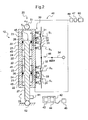
- each servocontrol 10 comprises a jack 20 and a hydraulic distributor 30, or a servo-control device incorporated or not to the hydraulic distributor.
- This jack 20 comprises at least one body 21 cooperating with a sliding element 25. According to the example shown, the jack 20 comprises two bodies 21.
- each body 21 defines an internal space 22. Therefore, the sliding element 25 is provided with a power rod 27 carrying a piston 26 for each internal space, each piston 26 sliding in the associated internal space 22.
- each piston 26 defines an extension chamber 23 and a retraction chamber 24 of the associated internal space.
- the jack 20 includes fastening means to the aircraft, such as a fixing means 51 of the body 21 and a fixing means 52 of the power rod 25.
- the servocontrol being a servocontrol with movable body
- the fixing means 52 of the power rod 25 is fixed to a fixed element while the fixing means 51 of the body 21 can be fixed to the set of cyclic trays 4 for example.
- the hydraulic distributor 30 has the function of conveying a fluid from a hydraulic source 60 to a chamber of each internal space 22. Therefore, the hydraulic distributor 30 may comprise a hydraulic unit per internal space, each controlled by a control lever 34.
- each hydraulic unit comprises at least one inlet passage 33 and two openings of variable section 31 of distribution adapted to be in connection with the extension chamber 23 and the retraction chamber 24 of the associated internal space 22.
- the control lever 34 cooperates consequently with a mobile restriction means 32 which can at least partially close said inlet passage and said openings.
- control lever 34 When the control lever 34 is maneuvered to require the extension of the jack 20, this control lever 34 moves the restriction means 32 which connects the inlet passage 33 and the variable section opening 31 connected to the chamber extension 23 of the internal space. Conversely, the variable section opening 31 connected to the retraction chamber 24 of the space internal can be placed in communication with a fluid return hydraulic circuit.
- control lever 34 when the control lever 34 is operated to require the retraction of the cylinder 20, the control lever 34 moves the restriction means 32 which connects the inlet passage 33 and the variable section opening 31 connected to the retraction chamber of the internal space. Conversely, the opening 31 connected to the expansion chamber 23 may be placed in communication with a hydraulic return circuit.
- This hydraulic distributor can be of the type described in the literature.
- the current section at each instant of the variable-section aperture 31 supplying fluid to the internal space is a variable section as a function of the position of the control lever 34 and therefore of the position of the restriction means 32.
- the servocontrol 10 comprises a device 40 for determining the static force exerted on this servocontrol.
- This device 40 includes a computer 42 provided with a processor 43 and a main memory 44, the processor 43 executing instructions stored in the memory 44 to determine this static force.
- the device 40 comprises a measuring sensor 41 of the current displacement speed V of the sliding element 25 relative to the body 21 of the servocontrol 10.
- the measurement sensor 41 is then connected to the computer by a wired link or wireless not shown on the figure 2 .
- This measurement sensor 41 is possibly a sensor measuring the relative displacement between the sliding element 25 and the body 21.
- the processor determines the current displacement speed V of the sliding element 25 with respect to the body 21.
- the current displacement speed V of the sliding element 25 relative to the body 21 is thus determined.
- the figure 4 shows a diagram representing on the abscissa this current displacement velocity V of the sliding element 25 with respect to the body 21, and on the ordinate the static force exerted on the servocontrol 10.
- this static force is a function of this current speed of movement V.
- the graphical representation of these first and second relations has a first segment associated with the first relation in a positive quadrant Q1, and a second segment associated with the second relation in a negative quadrant Q2. It is understood that a segment is relative to the extension of the servocontrol, while another segment is relative to the retraction of the servocontrol.
- the maximum displacement speed is a constant, equal to the maximum speed of relative displacement between the sliding element 25 and the body 21 for an opening with a maximum variable section 31 of distribution of the hydraulic distributor and for a maximum fluid temperature, for example .
- the maximum displacement speed Vmax may vary according to the current value of the variable section of this opening.
- each possible value of the maximum displacement speed Vmax corresponds to an equation making it possible to obtain the static force.
- the figure 5 thus shows a diagram showing the static force as a function of the speed of displacement of the sliding element 25 with respect to the body 21.
- each segment of a quadrant corresponding to an opening of a given section. It is understood that the larger the section of an opening, the greater the maximum displacement speed.
- a current value of the variable section of the opening of the hydraulic distributor 30 supplying fluid to the internal space is determined.
- V max VS q * S 1 * 2 ⁇ * P in - P out S 0
- C q represents a predetermined pressure drop coefficient of the hydraulic distributor 30
- S 1 represents a current value of the variable section of the opening 31 supplying fluid to the internal space
- p represents the density of the fluid
- P in represents the feed pressure of the fluid entering the hydraulic distributor 30
- P out represents the outlet pressure of the fluid leaving the hydraulic distributor and of the fluid present in a chamber 23, 24 of space internal 22 fed by the hydraulic distributor 30
- S 0 represents the surface of a constant section of said piston 26,
- * represents the sign of the multiplication.
- the device 40 may then include an opening sensor 48 to determine the current value of the variable section of the opening of the hydraulic distributor supplying fluid to the internal space.
- This opening sensor 48 may be a position sensor of the control lever 34 connected to the computer by a link not shown in the figures, namely a wired or wireless link.
- the processor executes instructions from the main memory to deduce the current value S 1 .
- the device 40 includes a first pressure sensor 44 of the supply pressure P in connected to the computer 42 by unrepresented wired or wireless links.
- the device 40 may include at least a second pressure sensor 45 of the outlet pressure P out connected to the computer 42 by wired or non-wired links not shown in the figures, a plurality of sensors arranged in each chamber. extension 23 and retraction 24 of the body 21 for example.
- the computer can then determine in real time the maximum movement speed associated with a given position of the hydraulic distributor 40 using the equation programmed in its main memory 44, to deduce the static force exerted on the servocontrol.
- outlet pressure P out is proportional to half of the inlet pressure P in according to a given ratio of proportionality, or even equal to half of the inlet pressure P in . Therefore, it is not necessary to implement at least a second pressure sensor.
- this device 40 may include a temperature sensor 47 of the fluid supplying the hydraulic distributor 30.
- the processor of the computer 42 executes instructions for determining the coefficient of pressure loss C q and the density p as a function of the measured temperature, with the aid of usual means such as databases, charts or equations for example.
- the device 40 may comprise a warning means 46. Therefore, the alerting means 46 can be activated when the static force exceeds a predetermined threshold.
Claims (8)
- Verfahren zur Bestimmung der statischen Kraft, die von einer Servosteuerung (10) entwickelt wird, die eine Kolben-Zylinder-Einheit (20) und einen hydraulischen Verteiler (30) aufweist, wobei die Kolben-Zylinder-Einheit (20) mindestens einen Körper (21) aufweist, der einen Innenraum (22) begrenzt, und ein Gleitelement (25) mit einem Steuerkolben (26), der in dem Innenraum (22) gleitet, wobei der hydraulische Verteiler (30) den Innenraum (22) mit einem Fluid speist, dadurch gekennzeichnet, dass:- man die aktuelle Geschwindigkeit der Relativbewegung des Gleitelements (25) bezüglich des Körpers (21) der Servosteuerung (10) bestimmt,- man die statische Kraft bestimmt mit Hilfewobei "F" die von der Servosteuerung (10) entwickelte statische Kraft bezeichnet, "Fmax" eine maximale vorbestimmte statische Kraft bezeichnet, die von der Servosteuerung (10) entwickelbar ist, "V2" das Quadrat der aktuellen Bewegungsgeschwindigkeit bezeichnet,• der folgenden ersten Beziehung, wenn die aktuelle Bewegungsgeschwindigkeit positiv ist:
 • der folgenden zweiten Beziehung, wenn die aktuelle Bewegungsgeschwindigkeit negativ ist:

- Verfahren nach Anspruch 1,
dadurch gekennzeichnet, dass:- man die aktuelle Geschwindigkeit (V) der Bewegung des Gleitelements (25) relativ zu dem Körper (21) der Servosteuerung (10) mit Hilfe eines Sensors (41) zur Messung der Bewegungsgeschwindigkeit bestimmt,- ein Rechner (42) mit einem Prozessor (43) und einem Hauptspeicher (44) Befehle bezüglich der ersten Beziehung und der zweiten Beziehung speichert, wobei die statische Kraft mit Hilfe der ersten Beziehung und der zweiten Beziehung bestimmt wird, indem die Befehle mit dem Prozessor (43) ausgeführt werden. - Verfahren nach einem der Ansprüche 1 bis 2,
dadurch gekennzeichnet, dass die aktuelle Bewegungsgeschwindigkeit (V) in Echtzeit bestimmt wird, indem ein Durchsatz des Fluids bestimmt wird, und dieser Durchsatz durch die Fläche (S0) eines konstanten Querschnitts des Kolbens dividiert wird. - Verfahren nach einem der Ansprüche 1 bis 2,
dadurch gekennzeichnet, dass der Hydraulikverteiler (30) mit dem Innenraum (22) über eine Öffnung (31) mit variablem Querschnitt verbunden ist, wobei der Hydraulikverteiler (30) ein mobiles Begrenzungsmittel (32) aufweist, um den variablen Querschnitt einzustellen, wobei ein aktueller Wert des variablen Querschnitts des Hydraulikverteilers (30) bestimmt wird, und die maximale Bewegungsgeschwindigkeit (Vmax) in Echtzeit mit Hilfe der folgenden Gleichung bestimmt wird:
wobei "Cq" einen vorbestimmten Druckverlustkoeffizienten des Hydraulikverteilers (30) bezeichnet, "S1" einen aktuellen Wert des variablen Querschnitts bezeichnet, "p" die Dichte des Fluids bezeichnet, "Pin" den Speisedruck des Fluids beim Eintritt in den Hydraulikverteiler (30) bezeichnet, "Pout" den Ausgangsdruck des den Hydraulikverteiler verlassenden Fluids bezeichnet, "S0" die Fläche eines konstanten Querschnitts des Kolbens (26) bezeichnet, und "*" das Multiplikationszeichen bezeichnet. - Verfahren nach Anspruch 4,
dadurch gekennzeichnet, dass man die maximale Bewegungsgeschwindigkeit Vmax in Echtzeit bestimmt mit Hilfe der Gleichung, indem man die Befehle mit einem Prozessor (43) eines Rechners (42) ausführt. - Verfahren nach Anspruch 4,
dadurch gekennzeichnet, dass der Ausgangsdruck (Pout) proportional zum Eingangsdruck (Pin) ist. - Verfahren nach Anspruch 4,
dadurch gekennzeichnet, dass man die Temperatur des Fluids misst, wobei der Druckverlustkoeffizient (Cq) und die Dichte (p) in Abhängigkeit von der Temperatur bestimmt werden. - Verfahren nach einem der Ansprüche 1 bis 7,
dadurch gekennzeichnet, dass ein Alarm ausgelöst wird, wenn die statische Kraft (F) einen vorbestimmten Wert überschreitet.
Applications Claiming Priority (1)
| Application Number | Priority Date | Filing Date | Title |
|---|---|---|---|
| FR1101611A FR2975774B1 (fr) | 2011-05-25 | 2011-05-25 | Procede de determination de l'effort statique developpe par une servocommande |
Publications (2)
| Publication Number | Publication Date |
|---|---|
| EP2527660A1 EP2527660A1 (de) | 2012-11-28 |
| EP2527660B1 true EP2527660B1 (de) | 2014-01-08 |
Family
ID=46051645
Family Applications (1)
| Application Number | Title | Priority Date | Filing Date |
|---|---|---|---|
| EP12003792.4A Active EP2527660B1 (de) | 2011-05-25 | 2012-05-14 | Verfahren zur Bestimmung der statischen Kraft, die von einer Servosteuerung entwickelt wird |
Country Status (5)
| Country | Link |
|---|---|
| US (1) | US9115735B2 (de) |
| EP (1) | EP2527660B1 (de) |
| KR (1) | KR101321115B1 (de) |
| CN (1) | CN102795334B (de) |
| FR (1) | FR2975774B1 (de) |
Families Citing this family (2)
| Publication number | Priority date | Publication date | Assignee | Title |
|---|---|---|---|---|
| FR2975774B1 (fr) * | 2011-05-25 | 2014-01-17 | Eurocopter France | Procede de determination de l'effort statique developpe par une servocommande |
| CN108088599A (zh) * | 2017-12-01 | 2018-05-29 | 中国直升机设计研究所 | 一种直升机电磁作动器输出力变化特性测试方法 |
Family Cites Families (18)
| Publication number | Priority date | Publication date | Assignee | Title |
|---|---|---|---|---|
| FR2236132B1 (de) * | 1973-07-03 | 1983-11-18 | Messier Hispano Sa | |
| US3892164A (en) | 1973-12-19 | 1975-07-01 | Mimik Limited | Servo control for machine tools |
| US4793188A (en) * | 1986-01-14 | 1988-12-27 | Texas Instruments Incorporated | Lubrication sensor apparatus |
| US5829335A (en) | 1993-05-11 | 1998-11-03 | Mannesmann Rexroth Gmbh | Control for hydraulic drive or actuator |
| DE4335403C1 (de) * | 1993-10-18 | 1994-12-15 | Karl Hehl | Hydraulikeinrichtung |
| AU5311496A (en) * | 1995-03-14 | 1996-10-02 | Boeing Company, The | Aircraft hydraulic pump control system |
| GB9919814D0 (en) * | 1999-08-20 | 1999-10-27 | Dowty Boulton Paul Ltd | Transducer |
| DE10256923B4 (de) * | 2002-12-05 | 2013-10-24 | Liebherr-France S.A. | Verfahren und Vorrichtung zur Bewegungsdämpfung von Hydraulikzylindern mobiler Arbeitsmaschinen |
| GB0328935D0 (en) * | 2003-12-12 | 2004-01-14 | Goodrich Actuation Systems Ltd | Hydraulic control valve |
| CN101375359B (zh) * | 2006-03-17 | 2011-07-27 | 三菱电机株式会社 | 状态把握装置以及具备该状态把握装置的开闭控制装置 |
| DE102006033487A1 (de) | 2006-07-19 | 2008-01-31 | Robert Bosch Gmbh | Verfahren zur Unterstützung eines Überholvorgangs bei einem Kraftfahrzeug |
| DE102007007005B4 (de) * | 2007-02-08 | 2021-12-02 | Robert Bosch Gmbh | Elektrohydraulische Steueranordnung |
| DE102007051857B3 (de) * | 2007-10-30 | 2009-04-23 | Siemens Ag | Regeleinrichtung zum Positionsregeln einer Hydraulikzylindereinheit mit Linearisierungseinheit |
| US20130132032A1 (en) * | 2008-03-31 | 2013-05-23 | Berin McKeown | System, device and associated methods for monitoring a physical condition or operating performance of a structure |
| US8671822B2 (en) | 2009-08-04 | 2014-03-18 | Depiak Industrial Technology Corporation | Fluid driven reciprocating linear motor |
| FR2962774B1 (fr) * | 2010-07-19 | 2012-08-03 | Eurocopter France | Servocommande munie d'un dispositif de detection d'effort limite |
| US9658627B2 (en) * | 2011-05-05 | 2017-05-23 | The Boeing Company | Detection of imminent control instability |
| FR2975774B1 (fr) * | 2011-05-25 | 2014-01-17 | Eurocopter France | Procede de determination de l'effort statique developpe par une servocommande |
-
2011
- 2011-05-25 FR FR1101611A patent/FR2975774B1/fr not_active Expired - Fee Related
-
2012
- 2012-05-14 EP EP12003792.4A patent/EP2527660B1/de active Active
- 2012-05-22 US US13/477,342 patent/US9115735B2/en not_active Expired - Fee Related
- 2012-05-23 KR KR1020120055065A patent/KR101321115B1/ko active IP Right Grant
- 2012-05-24 CN CN201210165512.4A patent/CN102795334B/zh active Active
Also Published As
| Publication number | Publication date |
|---|---|
| US9115735B2 (en) | 2015-08-25 |
| KR20120132378A (ko) | 2012-12-05 |
| CN102795334B (zh) | 2014-12-24 |
| KR101321115B1 (ko) | 2013-10-23 |
| FR2975774A1 (fr) | 2012-11-30 |
| CN102795334A (zh) | 2012-11-28 |
| EP2527660A1 (de) | 2012-11-28 |
| US20120303296A1 (en) | 2012-11-29 |
| FR2975774B1 (fr) | 2014-01-17 |
Similar Documents
| Publication | Publication Date | Title |
|---|---|---|
| EP3421357B1 (de) | Fahrwerk, das mit einem integrierten ladungsmessgerät für ein luftfahrzeug ausgestattet ist, und luftfahrzeug | |
| EP2505502B1 (de) | Verfahren, Vorrichtung zur Unterstützung der Steuerung eines Luftfahrzeugs, und Luftfahrzeug | |
| EP2634447B1 (de) | Elektrische bremse für rad eines luftfahrzeugs, das mit einem elektromechanischen stellglied mit einem temperatursensor ausgestattet ist | |
| EP3702269B1 (de) | Haptischer warnmechanismus zur warnung eines piloten eines flugzeugs und flugzeug | |
| EP2623417B1 (de) | Steuerverfahren eines Ausrichtungsbefehls eines Gelenkteils eines Flugzeugfahrwerks | |
| EP3753844B1 (de) | Steuerknüppel und hybrid-drehflügelflugzeug, das mit einem auftriebsrotor und mindestens einem schub erzeugenden propellervortriebsrotor ausgestattet ist | |
| CA3037781C (fr) | Procede d'engagement de deux elements engrenage et dispositif d'entrainement mettant en oeuvre un tel procede | |
| EP2527660B1 (de) | Verfahren zur Bestimmung der statischen Kraft, die von einer Servosteuerung entwickelt wird | |
| EP3060929B1 (de) | Verfahren und vorrichtung zur messung des winkels eines angriffs und des schiebewinkels eines flugzeugs | |
| FR3097527A1 (fr) | Procédé d’aide au pilotage d’un giravion hybride muni d’un rotor de sustentation et d’au moins un rotor propulsif à hélice générant une poussée | |
| EP3251955B1 (de) | Verfahren und hilfsvorrichtung zur steuerung eines luftfahrzeugs, und luftfahrzeug | |
| EP3546792B1 (de) | Verfahren zum eingriff zweier zahnräder und antriebsvorrichtung zur durchführung eines derartigen verfahrens | |
| EP3771649B1 (de) | System zur bewertung des verstopfungsgrads eines filters in einem luftfahrzeug, luftfahrzeug, das über ein solches bewertungssystem verfügt, und entsprechende methode | |
| EP3647192B1 (de) | Pilotenassistenzverfahren und -vorrichtung eines hybrid-drehflügelflugzeugs, das mit einem auftriebsrotor und mindestens einem schuberzeugenden vortriebsrotor ausgestattet ist | |
| EP2410188B1 (de) | Servobetätiger mit maximalkraftmessgerät | |
| EP2446149B1 (de) | Vorrichtung und verfahren zur positionierung einer ausrüstung mit veränderlicher geometrie für eine turbomaschine mit einem heber mit relativer messung | |
| EP4041628A1 (de) | System zum steuern der zyklischen einstellung von schaufeln | |
| EP3042847B1 (de) | Servosteuerung und luftfahrzeug, das mit einer solchen servosteuerung ausgestattet ist | |
| EP3620687A1 (de) | Verbindungsverfahren von zwei verzahnungselementen, und antriebsvorrichtung, bei der dieses verfahren angewandt wird | |
| FR3045714A1 (fr) | Pale ajustable en fonctionnement, rotor de machine tournante, machine tournante et aeronef | |
| FR2681310A1 (fr) | Dispositif pour la detection du givrage des pales d'un rotor d'aeronef. | |
| FR2986325A1 (fr) | Procede de determination de la presence d'une fuite sur un equipement hydraulique, dispositif, servocommande et aeronef associes | |
| FR3086638A1 (fr) | Atterriseur a balancier motorise et aeronef | |
| FR2872484A1 (fr) | Dispositif d'arbres d'entrainement pour commandes de vol d'aeronef |
Legal Events
| Date | Code | Title | Description |
|---|---|---|---|
| PUAI | Public reference made under article 153(3) epc to a published international application that has entered the european phase |
Free format text: ORIGINAL CODE: 0009012 |
|
| AK | Designated contracting states |
Kind code of ref document: A1 Designated state(s): AL AT BE BG CH CY CZ DE DK EE ES FI FR GB GR HR HU IE IS IT LI LT LU LV MC MK MT NL NO PL PT RO RS SE SI SK SM TR |
|
| AX | Request for extension of the european patent |
Extension state: BA ME |
|
| 17P | Request for examination filed |
Effective date: 20130110 |
|
| RIC1 | Information provided on ipc code assigned before grant |
Ipc: F15B 15/28 20060101AFI20130429BHEP Ipc: F15B 20/00 20060101ALI20130429BHEP Ipc: G01L 1/00 20060101ALI20130429BHEP |
|
| GRAP | Despatch of communication of intention to grant a patent |
Free format text: ORIGINAL CODE: EPIDOSNIGR1 |
|
| INTG | Intention to grant announced |
Effective date: 20130815 |
|
| GRAS | Grant fee paid |
Free format text: ORIGINAL CODE: EPIDOSNIGR3 |
|
| GRAA | (expected) grant |
Free format text: ORIGINAL CODE: 0009210 |
|
| AK | Designated contracting states |
Kind code of ref document: B1 Designated state(s): AL AT BE BG CH CY CZ DE DK EE ES FI FR GB GR HR HU IE IS IT LI LT LU LV MC MK MT NL NO PL PT RO RS SE SI SK SM TR |
|
| REG | Reference to a national code |
Ref country code: GB Ref legal event code: FG4D Free format text: NOT ENGLISH |
|
| REG | Reference to a national code |
Ref country code: CH Ref legal event code: EP |
|
| REG | Reference to a national code |
Ref country code: IE Ref legal event code: FG4D Free format text: LANGUAGE OF EP DOCUMENT: FRENCH |
|
| REG | Reference to a national code |
Ref country code: AT Ref legal event code: REF Ref document number: 648932 Country of ref document: AT Kind code of ref document: T Effective date: 20140215 |
|
| REG | Reference to a national code |
Ref country code: DE Ref legal event code: R096 Ref document number: 602012000750 Country of ref document: DE Effective date: 20140220 |
|
| RAP2 | Party data changed (patent owner data changed or rights of a patent transferred) |
Owner name: AIRBUS HELICOPTERS |
|
| REG | Reference to a national code |
Ref country code: AT Ref legal event code: MK05 Ref document number: 648932 Country of ref document: AT Kind code of ref document: T Effective date: 20140108 |
|
| REG | Reference to a national code |
Ref country code: NL Ref legal event code: VDEP Effective date: 20140108 |
|
| REG | Reference to a national code |
Ref country code: LT Ref legal event code: MG4D |
|
| REG | Reference to a national code |
Ref country code: FR Ref legal event code: CD Owner name: AIRBUS HELICOPTERS, FR Effective date: 20140602 |
|
| PG25 | Lapsed in a contracting state [announced via postgrant information from national office to epo] |
Ref country code: IS Free format text: LAPSE BECAUSE OF FAILURE TO SUBMIT A TRANSLATION OF THE DESCRIPTION OR TO PAY THE FEE WITHIN THE PRESCRIBED TIME-LIMIT Effective date: 20140508 Ref country code: LT Free format text: LAPSE BECAUSE OF FAILURE TO SUBMIT A TRANSLATION OF THE DESCRIPTION OR TO PAY THE FEE WITHIN THE PRESCRIBED TIME-LIMIT Effective date: 20140108 Ref country code: NO Free format text: LAPSE BECAUSE OF FAILURE TO SUBMIT A TRANSLATION OF THE DESCRIPTION OR TO PAY THE FEE WITHIN THE PRESCRIBED TIME-LIMIT Effective date: 20140408 |
|
| PG25 | Lapsed in a contracting state [announced via postgrant information from national office to epo] |
Ref country code: NL Free format text: LAPSE BECAUSE OF FAILURE TO SUBMIT A TRANSLATION OF THE DESCRIPTION OR TO PAY THE FEE WITHIN THE PRESCRIBED TIME-LIMIT Effective date: 20140108 Ref country code: SE Free format text: LAPSE BECAUSE OF FAILURE TO SUBMIT A TRANSLATION OF THE DESCRIPTION OR TO PAY THE FEE WITHIN THE PRESCRIBED TIME-LIMIT Effective date: 20140108 Ref country code: CY Free format text: LAPSE BECAUSE OF FAILURE TO SUBMIT A TRANSLATION OF THE DESCRIPTION OR TO PAY THE FEE WITHIN THE PRESCRIBED TIME-LIMIT Effective date: 20140108 Ref country code: FI Free format text: LAPSE BECAUSE OF FAILURE TO SUBMIT A TRANSLATION OF THE DESCRIPTION OR TO PAY THE FEE WITHIN THE PRESCRIBED TIME-LIMIT Effective date: 20140108 Ref country code: AT Free format text: LAPSE BECAUSE OF FAILURE TO SUBMIT A TRANSLATION OF THE DESCRIPTION OR TO PAY THE FEE WITHIN THE PRESCRIBED TIME-LIMIT Effective date: 20140108 Ref country code: ES Free format text: LAPSE BECAUSE OF FAILURE TO SUBMIT A TRANSLATION OF THE DESCRIPTION OR TO PAY THE FEE WITHIN THE PRESCRIBED TIME-LIMIT Effective date: 20140108 Ref country code: PT Free format text: LAPSE BECAUSE OF FAILURE TO SUBMIT A TRANSLATION OF THE DESCRIPTION OR TO PAY THE FEE WITHIN THE PRESCRIBED TIME-LIMIT Effective date: 20140508 |
|
| PG25 | Lapsed in a contracting state [announced via postgrant information from national office to epo] |
Ref country code: HR Free format text: LAPSE BECAUSE OF FAILURE TO SUBMIT A TRANSLATION OF THE DESCRIPTION OR TO PAY THE FEE WITHIN THE PRESCRIBED TIME-LIMIT Effective date: 20140108 Ref country code: RS Free format text: LAPSE BECAUSE OF FAILURE TO SUBMIT A TRANSLATION OF THE DESCRIPTION OR TO PAY THE FEE WITHIN THE PRESCRIBED TIME-LIMIT Effective date: 20140108 Ref country code: LV Free format text: LAPSE BECAUSE OF FAILURE TO SUBMIT A TRANSLATION OF THE DESCRIPTION OR TO PAY THE FEE WITHIN THE PRESCRIBED TIME-LIMIT Effective date: 20140108 |
|
| REG | Reference to a national code |
Ref country code: DE Ref legal event code: R097 Ref document number: 602012000750 Country of ref document: DE |
|
| PG25 | Lapsed in a contracting state [announced via postgrant information from national office to epo] |
Ref country code: DK Free format text: LAPSE BECAUSE OF FAILURE TO SUBMIT A TRANSLATION OF THE DESCRIPTION OR TO PAY THE FEE WITHIN THE PRESCRIBED TIME-LIMIT Effective date: 20140108 Ref country code: EE Free format text: LAPSE BECAUSE OF FAILURE TO SUBMIT A TRANSLATION OF THE DESCRIPTION OR TO PAY THE FEE WITHIN THE PRESCRIBED TIME-LIMIT Effective date: 20140108 Ref country code: RO Free format text: LAPSE BECAUSE OF FAILURE TO SUBMIT A TRANSLATION OF THE DESCRIPTION OR TO PAY THE FEE WITHIN THE PRESCRIBED TIME-LIMIT Effective date: 20140108 Ref country code: CZ Free format text: LAPSE BECAUSE OF FAILURE TO SUBMIT A TRANSLATION OF THE DESCRIPTION OR TO PAY THE FEE WITHIN THE PRESCRIBED TIME-LIMIT Effective date: 20140108 |
|
| PLBE | No opposition filed within time limit |
Free format text: ORIGINAL CODE: 0009261 |
|
| STAA | Information on the status of an ep patent application or granted ep patent |
Free format text: STATUS: NO OPPOSITION FILED WITHIN TIME LIMIT |
|
| PG25 | Lapsed in a contracting state [announced via postgrant information from national office to epo] |
Ref country code: PL Free format text: LAPSE BECAUSE OF FAILURE TO SUBMIT A TRANSLATION OF THE DESCRIPTION OR TO PAY THE FEE WITHIN THE PRESCRIBED TIME-LIMIT Effective date: 20140108 Ref country code: SK Free format text: LAPSE BECAUSE OF FAILURE TO SUBMIT A TRANSLATION OF THE DESCRIPTION OR TO PAY THE FEE WITHIN THE PRESCRIBED TIME-LIMIT Effective date: 20140108 |
|
| REG | Reference to a national code |
Ref country code: DE Ref legal event code: R119 Ref document number: 602012000750 Country of ref document: DE |
|
| 26N | No opposition filed |
Effective date: 20141009 |
|
| PG25 | Lapsed in a contracting state [announced via postgrant information from national office to epo] |
Ref country code: LU Free format text: LAPSE BECAUSE OF FAILURE TO SUBMIT A TRANSLATION OF THE DESCRIPTION OR TO PAY THE FEE WITHIN THE PRESCRIBED TIME-LIMIT Effective date: 20140514 |
|
| REG | Reference to a national code |
Ref country code: DE Ref legal event code: R097 Ref document number: 602012000750 Country of ref document: DE Effective date: 20141009 |
|
| PG25 | Lapsed in a contracting state [announced via postgrant information from national office to epo] |
Ref country code: MC Free format text: LAPSE BECAUSE OF FAILURE TO SUBMIT A TRANSLATION OF THE DESCRIPTION OR TO PAY THE FEE WITHIN THE PRESCRIBED TIME-LIMIT Effective date: 20140108 |
|
| REG | Reference to a national code |
Ref country code: IE Ref legal event code: MM4A |
|
| REG | Reference to a national code |
Ref country code: DE Ref legal event code: R119 Ref document number: 602012000750 Country of ref document: DE Effective date: 20141202 |
|
| PG25 | Lapsed in a contracting state [announced via postgrant information from national office to epo] |
Ref country code: IE Free format text: LAPSE BECAUSE OF NON-PAYMENT OF DUE FEES Effective date: 20140514 Ref country code: DE Free format text: LAPSE BECAUSE OF NON-PAYMENT OF DUE FEES Effective date: 20141202 |
|
| PG25 | Lapsed in a contracting state [announced via postgrant information from national office to epo] |
Ref country code: SI Free format text: LAPSE BECAUSE OF FAILURE TO SUBMIT A TRANSLATION OF THE DESCRIPTION OR TO PAY THE FEE WITHIN THE PRESCRIBED TIME-LIMIT Effective date: 20140108 |
|
| REG | Reference to a national code |
Ref country code: CH Ref legal event code: PL |
|
| PG25 | Lapsed in a contracting state [announced via postgrant information from national office to epo] |
Ref country code: CH Free format text: LAPSE BECAUSE OF NON-PAYMENT OF DUE FEES Effective date: 20150531 Ref country code: LI Free format text: LAPSE BECAUSE OF NON-PAYMENT OF DUE FEES Effective date: 20150531 |
|
| PG25 | Lapsed in a contracting state [announced via postgrant information from national office to epo] |
Ref country code: MT Free format text: LAPSE BECAUSE OF FAILURE TO SUBMIT A TRANSLATION OF THE DESCRIPTION OR TO PAY THE FEE WITHIN THE PRESCRIBED TIME-LIMIT Effective date: 20140108 |
|
| PG25 | Lapsed in a contracting state [announced via postgrant information from national office to epo] |
Ref country code: SM Free format text: LAPSE BECAUSE OF FAILURE TO SUBMIT A TRANSLATION OF THE DESCRIPTION OR TO PAY THE FEE WITHIN THE PRESCRIBED TIME-LIMIT Effective date: 20140108 |
|
| REG | Reference to a national code |
Ref country code: FR Ref legal event code: PLFP Year of fee payment: 5 |
|
| PG25 | Lapsed in a contracting state [announced via postgrant information from national office to epo] |
Ref country code: GR Free format text: LAPSE BECAUSE OF FAILURE TO SUBMIT A TRANSLATION OF THE DESCRIPTION OR TO PAY THE FEE WITHIN THE PRESCRIBED TIME-LIMIT Effective date: 20140409 Ref country code: BG Free format text: LAPSE BECAUSE OF FAILURE TO SUBMIT A TRANSLATION OF THE DESCRIPTION OR TO PAY THE FEE WITHIN THE PRESCRIBED TIME-LIMIT Effective date: 20140108 |
|
| PG25 | Lapsed in a contracting state [announced via postgrant information from national office to epo] |
Ref country code: BE Free format text: LAPSE BECAUSE OF FAILURE TO SUBMIT A TRANSLATION OF THE DESCRIPTION OR TO PAY THE FEE WITHIN THE PRESCRIBED TIME-LIMIT Effective date: 20140531 Ref country code: TR Free format text: LAPSE BECAUSE OF FAILURE TO SUBMIT A TRANSLATION OF THE DESCRIPTION OR TO PAY THE FEE WITHIN THE PRESCRIBED TIME-LIMIT Effective date: 20140108 Ref country code: HU Free format text: LAPSE BECAUSE OF FAILURE TO SUBMIT A TRANSLATION OF THE DESCRIPTION OR TO PAY THE FEE WITHIN THE PRESCRIBED TIME-LIMIT; INVALID AB INITIO Effective date: 20120514 |
|
| REG | Reference to a national code |
Ref country code: FR Ref legal event code: PLFP Year of fee payment: 6 |
|
| REG | Reference to a national code |
Ref country code: FR Ref legal event code: PLFP Year of fee payment: 7 |
|
| PG25 | Lapsed in a contracting state [announced via postgrant information from national office to epo] |
Ref country code: MK Free format text: LAPSE BECAUSE OF FAILURE TO SUBMIT A TRANSLATION OF THE DESCRIPTION OR TO PAY THE FEE WITHIN THE PRESCRIBED TIME-LIMIT Effective date: 20140108 |
|
| PG25 | Lapsed in a contracting state [announced via postgrant information from national office to epo] |
Ref country code: AL Free format text: LAPSE BECAUSE OF FAILURE TO SUBMIT A TRANSLATION OF THE DESCRIPTION OR TO PAY THE FEE WITHIN THE PRESCRIBED TIME-LIMIT Effective date: 20140108 |
|
| P01 | Opt-out of the competence of the unified patent court (upc) registered |
Effective date: 20230530 |
|
| PGFP | Annual fee paid to national office [announced via postgrant information from national office to epo] |
Ref country code: IT Payment date: 20230526 Year of fee payment: 12 Ref country code: FR Payment date: 20230526 Year of fee payment: 12 |
|
| PGFP | Annual fee paid to national office [announced via postgrant information from national office to epo] |
Ref country code: GB Payment date: 20230524 Year of fee payment: 12 |