EP2527660B1 - Method for determining the static force developed by a servocontrol - Google Patents
Method for determining the static force developed by a servocontrol Download PDFInfo
- Publication number
- EP2527660B1 EP2527660B1 EP12003792.4A EP12003792A EP2527660B1 EP 2527660 B1 EP2527660 B1 EP 2527660B1 EP 12003792 A EP12003792 A EP 12003792A EP 2527660 B1 EP2527660 B1 EP 2527660B1
- Authority
- EP
- European Patent Office
- Prior art keywords
- max
- hydraulic distributor
- static force
- travel speed
- determined
- Prior art date
- Legal status (The legal status is an assumption and is not a legal conclusion. Google has not performed a legal analysis and makes no representation as to the accuracy of the status listed.)
- Active
Links
Images

Classifications
-
- B—PERFORMING OPERATIONS; TRANSPORTING
- B64—AIRCRAFT; AVIATION; COSMONAUTICS
- B64C—AEROPLANES; HELICOPTERS
- B64C13/00—Control systems or transmitting systems for actuating flying-control surfaces, lift-increasing flaps, air brakes, or spoilers
- B64C13/24—Transmitting means
- B64C13/38—Transmitting means with power amplification
- B64C13/40—Transmitting means with power amplification using fluid pressure
-
- F—MECHANICAL ENGINEERING; LIGHTING; HEATING; WEAPONS; BLASTING
- F15—FLUID-PRESSURE ACTUATORS; HYDRAULICS OR PNEUMATICS IN GENERAL
- F15B—SYSTEMS ACTING BY MEANS OF FLUIDS IN GENERAL; FLUID-PRESSURE ACTUATORS, e.g. SERVOMOTORS; DETAILS OF FLUID-PRESSURE SYSTEMS, NOT OTHERWISE PROVIDED FOR
- F15B15/00—Fluid-actuated devices for displacing a member from one position to another; Gearing associated therewith
- F15B15/20—Other details, e.g. assembly with regulating devices
- F15B15/28—Means for indicating the position, e.g. end of stroke
- F15B15/2815—Position sensing, i.e. means for continuous measurement of position, e.g. LVDT
-
- F—MECHANICAL ENGINEERING; LIGHTING; HEATING; WEAPONS; BLASTING
- F15—FLUID-PRESSURE ACTUATORS; HYDRAULICS OR PNEUMATICS IN GENERAL
- F15B—SYSTEMS ACTING BY MEANS OF FLUIDS IN GENERAL; FLUID-PRESSURE ACTUATORS, e.g. SERVOMOTORS; DETAILS OF FLUID-PRESSURE SYSTEMS, NOT OTHERWISE PROVIDED FOR
- F15B20/00—Safety arrangements for fluid actuator systems; Applications of safety devices in fluid actuator systems; Emergency measures for fluid actuator systems
- F15B20/007—Overload
-
- G—PHYSICS
- G01—MEASURING; TESTING
- G01L—MEASURING FORCE, STRESS, TORQUE, WORK, MECHANICAL POWER, MECHANICAL EFFICIENCY, OR FLUID PRESSURE
- G01L1/00—Measuring force or stress, in general
- G01L1/02—Measuring force or stress, in general by hydraulic or pneumatic means
-
- F—MECHANICAL ENGINEERING; LIGHTING; HEATING; WEAPONS; BLASTING
- F15—FLUID-PRESSURE ACTUATORS; HYDRAULICS OR PNEUMATICS IN GENERAL
- F15B—SYSTEMS ACTING BY MEANS OF FLUIDS IN GENERAL; FLUID-PRESSURE ACTUATORS, e.g. SERVOMOTORS; DETAILS OF FLUID-PRESSURE SYSTEMS, NOT OTHERWISE PROVIDED FOR
- F15B2211/00—Circuits for servomotor systems
- F15B2211/60—Circuit components or control therefor
- F15B2211/63—Electronic controllers
- F15B2211/6303—Electronic controllers using input signals
- F15B2211/6336—Electronic controllers using input signals representing a state of the output member, e.g. position, speed or acceleration
Definitions
- the present invention relates to a method for determining the static force developed by a servocontrol.
- an aircraft comprises actuators maneuverable by a pilot, such as the blades of a lift rotor of a helicopter-type rotorcraft or the rudders of an airplane for example.
- the kinematic chain connecting a flight control to an operating member is often provided with a hydraulic system comprising a servo control allowing the pilot to steer the aircraft without difficulty and with precision.
- a helicopter is provided with a main rotor ensuring its lift and propulsion.
- a pilot changes the pitch of the main rotor blades, that is to say their incidence relative to the incident airflow.
- the rotorcraft comprises a set of cyclic trays provided with a lower non-rotating plate and a rotating upper plate, this assembly being sometimes more simply called "swashplate".
- the lower non-rotating plate is connected to the flight controls of the pilot, generally by three separate control lines while the upper rotating plate is connected to each blade respectively by a connecting rod.
- the swash plate thus slides along the main rotor mast to control the general pitch of the main rotor blades while being able to oscillate in all directions around a ball joint to control the cyclic pitch of the blades.
- Oscillations and the vertical displacement of the swashplate, controlled by the pilot, are therefore at the origin of the variation of the pitch of the blades allowing the pilot to steer the helicopter.
- the pilot controls the swashplate via mechanical controls linked to this swashplate by connecting rods.
- the efforts to be made by the pilot to maneuver the swashplate are very important, especially if the mass of the rotorcraft is also important.
- a servo control of a hydraulic system is then arranged between an upstream portion and a downstream portion of each drive kinematic chain.
- the pilot then solicits the servo drives without special efforts via the upstream portion, then these servocontrols transcribe the order of the pilot and act on the downstream portion of the driveline.
- a helicopter is provided with a rear rotor whose pitch of the blades can be modified via a servo.
- the servocontrols comprise a jack provided with at least one cylindrical external body in which a sliding element with a power rod equipped with a control piston is translated.
- This control piston defines a retraction chamber and an expansion chamber inside this outer body.
- the servo control comprises a hydraulic distributor supplying fluid to the retraction chamber or the expansion chamber according to the order received.
- the displacement of the control piston of the sliding element relative to the outer body is then controlled by the hydraulic distributor which is actuated by the flight controls of the pilot of the helicopter, through the upstream portion of a kinematic chain.
- the hydraulic distributor supplies the retraction chamber or the expansion chamber with hydraulic fluid to require retraction or extension of the servocontrol.
- retract chamber a chamber causing the retraction of the servo control when said chamber is filled with a fluid.
- an “expansion chamber” is a chamber causing the extension of the servocontrol when said chamber is filled with a fluid.
- the servo control may further comprise a servo device, possibly integrated with the hydraulic distributor.
- the power rod is fixed on a fixed point of the aircraft belonging for example to a power transmission box, the body moving according to the orders received and being connected to the downstream portion of the drive train.
- the person skilled in the art denominates this type of servocontrol according to the expression "servocontrol with moving body”.
- the body is fixed to a fixed point of the aircraft, the power rod moving according to the orders received and being connected to the downstream portion of the kinematic chain.
- the skilled person thus denominates this type of servo control according to the expression "servocontrol with fixed body”.
- a single-body servocontrol is then provided with a jack provided with a body defining a single internal space delimiting a retraction chamber and an expansion chamber separated by a control piston.
- the retraction chamber and the expansion chamber are then fed by a hydraulic distributor provided with a single hydraulic unit.
- This servo perfectly fulfills its function. However, for safety reasons, the skilled person tends, from a certain level of effort to develop, to use a servocontrol at least double body.
- a double-body servo control then comprises a jack provided with a lower body and an upper body assembled in tandem or parallel.
- a tandem double body servo control includes a sliding element with a power rod carrying two pistons, each piston delimiting in each body a retraction chamber and an expansion chamber.
- two hydraulic units of the hydraulic distributor actuated by a common control lever connected to the controls of the driver, respectively feed the retraction chambers and extension of the lower and upper bodies.
- a limit static force detection device on a servocontrol.
- the static force exerted on the servocontrol reaches a threshold limit, namely a static traction force or a static compression force
- the limit static force detection device triggers an alert to inform the pilot.
- the limit static force detection device comprises a detection element provided with a rod equipped with a detection piston sliding in a detection space, this detection space comprising two detection chambers delimited by the detection piston , independent of the retraction and extension chambers of the external body.
- the first detection chamber is supplied with fluid by the hydraulic circuit of the aircraft, the second detection chamber opening onto the outside of the servocontrol.
- the rod of the detection element protrudes from the body of the servo control to be connected to the downstream portion of the kinematic chain for example.
- This projecting portion of the detection element further comprises a lever adapted to cooperate with a push-button switch.
- the pressure in the sensing chamber keeps the sensing piston in high abutment so as to move its lever away from the switch.
- the threshold is reached, the pressure prevailing in the detection chamber no longer makes it possible to keep the detection piston in high abutment.
- the detection piston thus reaches a low stop, the lever then actuating the switch.
- the detection piston In order to prevent a passage of the fluid from the first detection chamber to the outside of the servocontrol, the detection piston has a seal. Since this seal is dynamically stressed, leakage towards the outside of the servocontrol may appear and lead to maintenance actions.
- the limit static force detection device is subjected to the forces experienced by the servo control being connected to the drive kinematic chain. Therefore, it is sized to support these efforts. This results in a significant financial cost and mass.
- the sliding of the detection piston in fact induces a game in the control kinematic chain in the event of a pressure drop in the hydraulic circuit supplying fluid to the limit static force detection device.
- a servocontrol provided with at least one limit force detection device.
- This device comprises a housing integral with a body of the servocontrol, the housing delimiting a detection space.
- a movable member shares this detection space in a first detection chamber opening on an internal space of said body and in a second detection chamber.
- the device has a means for detecting the position of the movable member in the detection space.
- the state of the art further includes the document WO 2008/095525 , the document US 2004/0128868 and the document US 2010/0294125
- the present invention therefore has the particular object of proposing an alternative method and servocontrol enabling in particular to overcome the aforementioned limitations.
- the servocontrol may be a servocontrol comprising a body or a plurality of bodies.
- the hydraulic distributor having an opening of variable section to feed a chamber of the internal space, the maximum displacement speed Vmax corresponds to the speed of movement of the sliding element in the absence of a static force applied to the servocontrol.
- the maximum displacement speed Vmax may be a constant, or even be considered as a variable depending on the current section of the variable section or even the temperature of the fluid. It is understood that the term "current section”, the value of the variable section at each moment, namely in real time.
- This method may comprise in addition one or more of the additional characteristics which follow.
- said current displacement speed V is determined in real time by determining a flow rate of said fluid by means of a means for measuring the usual flow rate, and then by dividing said flow rate by the surface of a constant section of the piston.
- the flow rate can be the flow rate of the fluid through the hydraulic distributor.
- the maximum displacement speed may alternatively be a constant predetermined by the manufacturer, possibly corresponding to the maximum speed of displacement of the sliding element when the opening of the hydraulic distributor supplying the cylinder is maximum and at a maximum temperature the range of use of the fluid envisaged.
- the hydraulic distributor communicating with the internal space by a variable section opening, this hydraulic distributor comprising a movable restriction means for adjusting the variable section, it is possible to determine a current value of the variable section of the hydraulic distributor.
- V max VS q * S 1 * 2 ⁇ * P in - P out S 0 .
- C q represents a predetermined pressure drop coefficient of the hydraulic distributor
- S 1 represents the current value of the variable section
- ⁇ represents the density of the fluid supplying the servocontrol
- P in represents the pressure supplying the fluid entering the hydraulic distributor
- P out represents the outlet pressure of the fluid leaving the hydraulic distributor
- S 0 represents the surface of a constant section of the piston
- * represents the sign of the multiplication.
- outlet pressure represents the pressure of the fluid leaving the hydraulic distributor, ie the pressure of the fluid present in a chamber of the internal space supplied by the hydraulic distributor.
- the pressure drop coefficient C q corresponds to the pressure drop of the hydraulic distributor between the inlet and the outlet of this hydraulic distributor, this coefficient being established by tests and which can be variable depending on the temperature of the fluid, for example.
- the density of the fluid may be a predetermined constant, or a variable established according to said fluid temperature.
- a processor of a computer executes, for example, instructions for determining the current value of the variable section, by using a position or movement sensor of the restriction means or even of a control lever of the hydraulic distributor, for example . Since the current section of the opening of the hydraulic distributor depends directly on the position of the restriction means, the calculator can easily determine this current section.
- the computer then deduces the maximum movement speed and the static force exerted on the servocontrol.
- outlet pressure of the hydraulic distributor can be established from the inlet pressure of the hydraulic distributor, possibly using an equation called "pressure equation” for convenience.
- the outlet pressure is proportional to the inlet pressure, the proportionality ratio being determined by tests by example.
- the outlet pressure is equal to half of the inlet pressure.
- the pressure drop coefficient and the density may be predetermined constants.
- a calculator can determine the coefficient of pressure loss and this density using databases, stored curves, or equations providing this coefficient of pressure loss and density according to said temperature.
- an alert is triggered when the static force exceeds a predetermined threshold.
- the computer triggers an audible or visual type alert. It is understood that it is possible to perform other post-treatments following the determination of the static force.
- the invention relates to a device implementing this method.
- this device can be implemented on existing servocontrols, these servocontrols generally being provided with a sensor for measuring the speed of displacement of the sliding element relative to the body.
- the device may comprise an alert means connected to the computer, the processor executing the stored instructions for soliciting the alert means when the static force exceeds a predetermined threshold.
- the invention provides a servocontrol provided with a cylinder and a hydraulic distributor, the servocontrol comprising at least one body delimiting an internal space and a sliding element provided with a sliding control piston in the internal space, the hydraulic distributor supplying the internal space with a fluid.
- This servocontrol is particularly notable in that it comprises a device according to the invention as described above.
- the invention is an aircraft provided with such a servo.
- the figure 1 presents an aircraft 1, and more particularly a rotorcraft equipped with a cell 3 carrying a main rotor 2 and a rear rotor 5 not visible.
- This aircraft 1 then comprises a set of cyclic trays 4 to adjust the pitch of the main rotor blades 2, this set of cyclic trays being controlled by three servocontrols 10 connected to flight controls not shown on the figure 1 .
- control chain controlling the pitch of the blades of the tail rotor 5 may comprise a servo control not shown on this figure 1 .
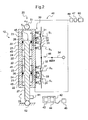
- each servocontrol 10 comprises a jack 20 and a hydraulic distributor 30, or a servo-control device incorporated or not to the hydraulic distributor.
- This jack 20 comprises at least one body 21 cooperating with a sliding element 25. According to the example shown, the jack 20 comprises two bodies 21.
- each body 21 defines an internal space 22. Therefore, the sliding element 25 is provided with a power rod 27 carrying a piston 26 for each internal space, each piston 26 sliding in the associated internal space 22.
- each piston 26 defines an extension chamber 23 and a retraction chamber 24 of the associated internal space.
- the jack 20 includes fastening means to the aircraft, such as a fixing means 51 of the body 21 and a fixing means 52 of the power rod 25.
- the servocontrol being a servocontrol with movable body
- the fixing means 52 of the power rod 25 is fixed to a fixed element while the fixing means 51 of the body 21 can be fixed to the set of cyclic trays 4 for example.
- the hydraulic distributor 30 has the function of conveying a fluid from a hydraulic source 60 to a chamber of each internal space 22. Therefore, the hydraulic distributor 30 may comprise a hydraulic unit per internal space, each controlled by a control lever 34.
- each hydraulic unit comprises at least one inlet passage 33 and two openings of variable section 31 of distribution adapted to be in connection with the extension chamber 23 and the retraction chamber 24 of the associated internal space 22.
- the control lever 34 cooperates consequently with a mobile restriction means 32 which can at least partially close said inlet passage and said openings.
- control lever 34 When the control lever 34 is maneuvered to require the extension of the jack 20, this control lever 34 moves the restriction means 32 which connects the inlet passage 33 and the variable section opening 31 connected to the chamber extension 23 of the internal space. Conversely, the variable section opening 31 connected to the retraction chamber 24 of the space internal can be placed in communication with a fluid return hydraulic circuit.
- control lever 34 when the control lever 34 is operated to require the retraction of the cylinder 20, the control lever 34 moves the restriction means 32 which connects the inlet passage 33 and the variable section opening 31 connected to the retraction chamber of the internal space. Conversely, the opening 31 connected to the expansion chamber 23 may be placed in communication with a hydraulic return circuit.
- This hydraulic distributor can be of the type described in the literature.
- the current section at each instant of the variable-section aperture 31 supplying fluid to the internal space is a variable section as a function of the position of the control lever 34 and therefore of the position of the restriction means 32.
- the servocontrol 10 comprises a device 40 for determining the static force exerted on this servocontrol.
- This device 40 includes a computer 42 provided with a processor 43 and a main memory 44, the processor 43 executing instructions stored in the memory 44 to determine this static force.
- the device 40 comprises a measuring sensor 41 of the current displacement speed V of the sliding element 25 relative to the body 21 of the servocontrol 10.
- the measurement sensor 41 is then connected to the computer by a wired link or wireless not shown on the figure 2 .
- This measurement sensor 41 is possibly a sensor measuring the relative displacement between the sliding element 25 and the body 21.
- the processor determines the current displacement speed V of the sliding element 25 with respect to the body 21.
- the current displacement speed V of the sliding element 25 relative to the body 21 is thus determined.
- the figure 4 shows a diagram representing on the abscissa this current displacement velocity V of the sliding element 25 with respect to the body 21, and on the ordinate the static force exerted on the servocontrol 10.
- this static force is a function of this current speed of movement V.
- the graphical representation of these first and second relations has a first segment associated with the first relation in a positive quadrant Q1, and a second segment associated with the second relation in a negative quadrant Q2. It is understood that a segment is relative to the extension of the servocontrol, while another segment is relative to the retraction of the servocontrol.
- the maximum displacement speed is a constant, equal to the maximum speed of relative displacement between the sliding element 25 and the body 21 for an opening with a maximum variable section 31 of distribution of the hydraulic distributor and for a maximum fluid temperature, for example .
- the maximum displacement speed Vmax may vary according to the current value of the variable section of this opening.
- each possible value of the maximum displacement speed Vmax corresponds to an equation making it possible to obtain the static force.
- the figure 5 thus shows a diagram showing the static force as a function of the speed of displacement of the sliding element 25 with respect to the body 21.
- each segment of a quadrant corresponding to an opening of a given section. It is understood that the larger the section of an opening, the greater the maximum displacement speed.
- a current value of the variable section of the opening of the hydraulic distributor 30 supplying fluid to the internal space is determined.
- V max VS q * S 1 * 2 ⁇ * P in - P out S 0
- C q represents a predetermined pressure drop coefficient of the hydraulic distributor 30
- S 1 represents a current value of the variable section of the opening 31 supplying fluid to the internal space
- p represents the density of the fluid
- P in represents the feed pressure of the fluid entering the hydraulic distributor 30
- P out represents the outlet pressure of the fluid leaving the hydraulic distributor and of the fluid present in a chamber 23, 24 of space internal 22 fed by the hydraulic distributor 30
- S 0 represents the surface of a constant section of said piston 26,
- * represents the sign of the multiplication.
- the device 40 may then include an opening sensor 48 to determine the current value of the variable section of the opening of the hydraulic distributor supplying fluid to the internal space.
- This opening sensor 48 may be a position sensor of the control lever 34 connected to the computer by a link not shown in the figures, namely a wired or wireless link.
- the processor executes instructions from the main memory to deduce the current value S 1 .
- the device 40 includes a first pressure sensor 44 of the supply pressure P in connected to the computer 42 by unrepresented wired or wireless links.
- the device 40 may include at least a second pressure sensor 45 of the outlet pressure P out connected to the computer 42 by wired or non-wired links not shown in the figures, a plurality of sensors arranged in each chamber. extension 23 and retraction 24 of the body 21 for example.
- the computer can then determine in real time the maximum movement speed associated with a given position of the hydraulic distributor 40 using the equation programmed in its main memory 44, to deduce the static force exerted on the servocontrol.
- outlet pressure P out is proportional to half of the inlet pressure P in according to a given ratio of proportionality, or even equal to half of the inlet pressure P in . Therefore, it is not necessary to implement at least a second pressure sensor.
- this device 40 may include a temperature sensor 47 of the fluid supplying the hydraulic distributor 30.
- the processor of the computer 42 executes instructions for determining the coefficient of pressure loss C q and the density p as a function of the measured temperature, with the aid of usual means such as databases, charts or equations for example.
- the device 40 may comprise a warning means 46. Therefore, the alerting means 46 can be activated when the static force exceeds a predetermined threshold.
Description
La présente invention concerne un procédé de détermination de l'effort statique développé par une servocommande.The present invention relates to a method for determining the static force developed by a servocontrol.
Classiquement, un aéronef comporte des organes de manoeuvre manoeuvrables par un pilote, tels que les pales d'un rotor de sustentation d'un giravion de type hélicoptère ou encore des gouvernes de direction d'un avion par exemple.Conventionally, an aircraft comprises actuators maneuverable by a pilot, such as the blades of a lift rotor of a helicopter-type rotorcraft or the rudders of an airplane for example.
A l'aide de commandes de vol, le pilote manoeuvre donc les organes de manoeuvre de l'aéronef. Toutefois, les efforts à fournir sont parfois très importants pour déplacer ces organes de manoeuvre.With the aid of flight controls, the pilot maneuvers the maneuvering organs of the aircraft. However, the efforts to provide are sometimes very important to move these actuators.
Par suite, la chaîne cinématique reliant une commande de vol à un organe de manoeuvre est souvent munie d'un système hydraulique comprenant une servocommande permettant au pilote de gouverner l'aéronef sans difficulté et avec précision.As a result, the kinematic chain connecting a flight control to an operating member is often provided with a hydraulic system comprising a servo control allowing the pilot to steer the aircraft without difficulty and with precision.
Plus particulièrement, un hélicoptère est muni d'un rotor principal assurant sa sustentation et sa propulsion. Pour diriger l'hélicoptère, un pilote modifie le pas des pales du rotor principal, c'est-à-dire leurs incidences par rapport à l'écoulement d'air incident.More particularly, a helicopter is provided with a main rotor ensuring its lift and propulsion. To steer the helicopter, a pilot changes the pitch of the main rotor blades, that is to say their incidence relative to the incident airflow.
Par suite, le giravion comporte un ensemble de plateaux cycliques pourvu d'un plateau inférieur non tournant et d'un plateau supérieur tournant, cet ensemble étant parfois plus simplement dénommé « plateau cyclique ». Le plateau inférieur non tournant est relié aux commandes de vol du pilote, généralement par trois lignes de commande distinctes alors que le plateau supérieur tournant est relié à chaque pale respectivement par une bielle. Le plateau cyclique coulisse ainsi le long du mât du rotor principal pour commander le pas général des pales du rotor principal tout en pouvant osciller dans tous les sens autour d'une rotule pour commander le pas cyclique des pales.As a result, the rotorcraft comprises a set of cyclic trays provided with a lower non-rotating plate and a rotating upper plate, this assembly being sometimes more simply called "swashplate". The lower non-rotating plate is connected to the flight controls of the pilot, generally by three separate control lines while the upper rotating plate is connected to each blade respectively by a connecting rod. The swash plate thus slides along the main rotor mast to control the general pitch of the main rotor blades while being able to oscillate in all directions around a ball joint to control the cyclic pitch of the blades.
Les oscillations et le déplacement vertical du plateau cyclique, commandés par le pilote, sont donc à l'origine de la variation du pas des pales permettant au pilote de diriger l'hélicoptère.Oscillations and the vertical displacement of the swashplate, controlled by the pilot, are therefore at the origin of the variation of the pitch of the blades allowing the pilot to steer the helicopter.
Classiquement, le pilote commande le plateau cyclique via des commandes mécaniques liées à ce plateau cyclique par des bielles. Toutefois, les efforts à exercer par le pilote pour manoeuvrer le plateau cyclique sont très importants, en particulier si la masse du giravion est également importante.Conventionally, the pilot controls the swashplate via mechanical controls linked to this swashplate by connecting rods. However, the efforts to be made by the pilot to maneuver the swashplate are very important, especially if the mass of the rotorcraft is also important.
Par conséquent, une servocommande d'un système hydraulique est alors agencée entre une portion amont et une portion aval de chaque chaîne cinématique de commande. Le pilote sollicite alors les servocommandes sans efforts particuliers via la portion amont, puis ces servocommandes retranscrivent l'ordre du pilote et agissent sur la portion aval de la chaîne cinématique.Therefore, a servo control of a hydraulic system is then arranged between an upstream portion and a downstream portion of each drive kinematic chain. The pilot then solicits the servo drives without special efforts via the upstream portion, then these servocontrols transcribe the order of the pilot and act on the downstream portion of the driveline.
De même, un hélicoptère est pourvu d'un rotor arrière dont le pas des pales peut être modifiable via une servocommande.Similarly, a helicopter is provided with a rear rotor whose pitch of the blades can be modified via a servo.
Bien entendu, il en va de même pour des ailerons ou des volets d'avions, par exemple, manoeuvrés via des servocommandes.Of course, it is the same for fins or flaps of aircraft, for example, operated via servo.
On note que certains aéronefs modernes comportent des commandes de vol électriques qui remplacent les liaisons mécaniques reliant les commandes de vol aux servocommandes.It is noted that some modern aircraft include electric flight controls that replace the mechanical links connecting the flight controls to the servo controls.
De façon usuelle, les servocommandes comportent un vérin muni d'au moins un corps externe de forme cylindrique dans lequel translate un élément coulissant muni d'une tige de puissance équipée d'un piston de commande. Ce piston de commande délimite une chambre de rétraction et une chambre d'extension à l'intérieur de ce corps externe.In the usual way, the servocontrols comprise a jack provided with at least one cylindrical external body in which a sliding element with a power rod equipped with a control piston is translated. This control piston defines a retraction chamber and an expansion chamber inside this outer body.
De plus, la servocommande comporte un distributeur hydraulique alimentant en fluide la chambre de rétraction ou la chambre d'extension suivant l'ordre reçu. Le déplacement du piston de commande de l'élément coulissant par rapport au corps externe est alors commandé par le distributeur hydraulique qui est actionné par les commandes de vol du pilote de l'hélicoptère, au travers de la portion amont d'une chaîne cinématique. En fonction des ordres donnés, le distributeur hydraulique alimente en fluide hydraulique la chambre de rétraction ou la chambre d'extension pour requérir la rétraction ou l'extension de la servocommande.In addition, the servo control comprises a hydraulic distributor supplying fluid to the retraction chamber or the expansion chamber according to the order received. The displacement of the control piston of the sliding element relative to the outer body is then controlled by the hydraulic distributor which is actuated by the flight controls of the pilot of the helicopter, through the upstream portion of a kinematic chain. Depending on the orders given, the hydraulic distributor supplies the retraction chamber or the expansion chamber with hydraulic fluid to require retraction or extension of the servocontrol.
On comprend que l'on appelle dans la suite du texte « chambre de rétraction » une chambre provoquant la rétraction de la servocommande lorsque ladite chambre est remplie par un fluide. A l'inverse, on appelle « chambre d'extension » une chambre provoquant l'extension de la servocommande lorsque ladite chambre est remplie par un fluide.It is understood that hereinafter referred to as "retraction chamber" a chamber causing the retraction of the servo control when said chamber is filled with a fluid. Conversely, an "expansion chamber" is a chamber causing the extension of the servocontrol when said chamber is filled with a fluid.
La servocommande peut de plus comprendre un dispositif d'asservissement, éventuellement intégré au distributeur hydraulique.The servo control may further comprise a servo device, possibly integrated with the hydraulic distributor.
Deux modes de réalisation des servocommandes coexistent alors.Two embodiments of the servo coexist then.
Selon un premier mode de réalisation, la tige de puissance est fixée sur un point fixe de l'aéronef appartenant par exemple à une boîte de transmission de puissance, le corps se déplaçant en fonction des ordres reçus et étant reliée à la portion aval de la chaîne cinématique. L'homme du métier dénomme ce type de servocommande selon l'expression « servocommande à corps mobile ».According to a first embodiment, the power rod is fixed on a fixed point of the aircraft belonging for example to a power transmission box, the body moving according to the orders received and being connected to the downstream portion of the drive train. The person skilled in the art denominates this type of servocontrol according to the expression "servocontrol with moving body".
A contrario, selon un deuxième mode de réalisation, le corps est fixé à un point fixe de l'aéronef, la tige de puissance se déplaçant en fonction des ordres reçus et étant relié à la portion aval de la chaîne cinématique. L'homme du métier dénomme donc ce type de servocommande selon l'expression « servocommande à corps fixe ».In contrast, according to a second embodiment, the body is fixed to a fixed point of the aircraft, the power rod moving according to the orders received and being connected to the downstream portion of the kinematic chain. The skilled person thus denominates this type of servo control according to the expression "servocontrol with fixed body".
En outre, quel que soit le mode de réalisation, on connait des servocommandes dénommées à « simple corps » ou à « double corps » par l'homme du métier.In addition, whatever the embodiment, we know servocontrols called "single body" or "double body" by the skilled person.
Une servocommande à simple corps est alors munie d'un vérin pourvu d'un corps définissant un unique espace interne délimitant une chambre de rétraction et une chambre d'extension séparées par un piston de commande. La chambre de rétraction et la chambre d'extension sont alors alimentées par un distributeur hydraulique muni d'une unique unité hydraulique. Cette servocommande remplit parfaitement sa fonction. Néanmoins, pour des raisons de sécurité, l'homme du métier tend, à partir d'un certain niveau d'effort à développer, à utiliser une servocommande au moins à double corps.A single-body servocontrol is then provided with a jack provided with a body defining a single internal space delimiting a retraction chamber and an expansion chamber separated by a control piston. The retraction chamber and the expansion chamber are then fed by a hydraulic distributor provided with a single hydraulic unit. This servo perfectly fulfills its function. However, for safety reasons, the skilled person tends, from a certain level of effort to develop, to use a servocontrol at least double body.
Une servocommande à double corps comporte alors un vérin pourvu d'un corps inférieur et d'un corps supérieur assemblés en tandem ou en parallèle.A double-body servo control then comprises a jack provided with a lower body and an upper body assembled in tandem or parallel.
Par exemple, une servocommande à double corps en tandem comprend un élément coulissant muni d'une tige de puissance portant deux pistons, chaque piston délimitant dans chaque corps une chambre de rétraction et une chambre d'extension.For example, a tandem double body servo control includes a sliding element with a power rod carrying two pistons, each piston delimiting in each body a retraction chamber and an expansion chamber.
De plus, deux unités hydrauliques du distributeur hydraulique, actionnées par un levier de commande commun relié aux commandes du pilote, alimentent respectivement les chambres de rétraction et d'extension des corps inférieur et supérieur.In addition, two hydraulic units of the hydraulic distributor, actuated by a common control lever connected to the controls of the driver, respectively feed the retraction chambers and extension of the lower and upper bodies.
Il existe par ailleurs des servocommandes munies de trois corps, voire plus.There are also servocontrols with three or more bodies.
Durant un vol à grande vitesse, des évolutions extrêmes de l'aéronef peuvent introduire des contraintes mécaniques importantes dans la structure résistante de l'aéronef. Au-delà de facteurs de charge donnés, il y a un risque d'endommagement de cette structure.During a high-speed flight, extreme evolutions of the aircraft can introduce significant mechanical stresses into the resistant structure of the aircraft. Beyond given load factors, there is a risk of damage to this structure.
Pour prévenir le pilote que l'aéronef atteint une limite d'évolution, il est possible de prévoir un dispositif de détection d'effort statique limite sur une servocommande. Lorsque l'effort statique exercé sur la servocommande atteint un seuil limite, à savoir un effort statique de traction ou un effort statique de compression, le dispositif de détection d'effort statique limite déclenche une alerte pour en informer le pilote.To warn the pilot that the aircraft reaches an evolution limit, it is possible to provide a limit static force detection device on a servocontrol. When the static force exerted on the servocontrol reaches a threshold limit, namely a static traction force or a static compression force, the limit static force detection device triggers an alert to inform the pilot.
Classiquement, le dispositif de détection d'effort statique limite comprend un élément de détection muni d'une tige équipée d'un piston de détection coulissant dans un espace de détection, cet espace de détection comprenant deux chambres de détection délimitées par le piston de détection, indépendantes des chambres de rétraction et d'extension du corps externe. La première chambre de détection est alimentée en fluide par le circuit hydraulique de l'aéronef, la deuxième chambre de détection débouchant sur l'extérieur de la servocommande.Conventionally, the limit static force detection device comprises a detection element provided with a rod equipped with a detection piston sliding in a detection space, this detection space comprising two detection chambers delimited by the detection piston , independent of the retraction and extension chambers of the external body. The first detection chamber is supplied with fluid by the hydraulic circuit of the aircraft, the second detection chamber opening onto the outside of the servocontrol.
De plus, la tige de l'élément de détection saille du corps de la servocommande pour être reliée à la portion aval de la chaîne cinématique par exemple. Cette partie saillante de l'élément de détection comprend en outre un levier apte à coopérer avec un interrupteur à poussoir.In addition, the rod of the detection element protrudes from the body of the servo control to be connected to the downstream portion of the kinematic chain for example. This projecting portion of the detection element further comprises a lever adapted to cooperate with a push-button switch.
En dessous du seuil limite, la pression régnant dans la chambre de détection maintient le piston de détection en butée haute de manière à éloigner son levier de l'interrupteur. Par contre lorsque le seuil est atteint, la pression régnant dans la chambre de détection ne permet plus de maintenir le piston de détection en butée haute. Le piston de détection atteint donc une butée basse, le levier actionnant alors l'interrupteur.Below the threshold, the pressure in the sensing chamber keeps the sensing piston in high abutment so as to move its lever away from the switch. On the other hand, when the threshold is reached, the pressure prevailing in the detection chamber no longer makes it possible to keep the detection piston in high abutment. The detection piston thus reaches a low stop, the lever then actuating the switch.
Afin d'éviter un passage du fluide de la première chambre de détection vers l'extérieur de la servocommande, le piston de détection comporte un joint. Ce joint étant sollicité dynamiquement, des fuites vers l'extérieur de la servocommande peuvent apparaître et conduire à des actions de maintenance.In order to prevent a passage of the fluid from the first detection chamber to the outside of the servocontrol, the detection piston has a seal. Since this seal is dynamically stressed, leakage towards the outside of the servocontrol may appear and lead to maintenance actions.
De plus, le dispositif de détection d'effort statique limite est soumis aux efforts subis par la servocommande en étant relié à la chaîne cinématique de commande. Dès lors, il est dimensionné pour pouvoir supporter lesdits efforts. Il en résulte un coût financier et une masse non négligeables.In addition, the limit static force detection device is subjected to the forces experienced by the servo control being connected to the drive kinematic chain. Therefore, it is sized to support these efforts. This results in a significant financial cost and mass.
Enfin, le coulissement du piston de détection induit de fait un jeu dans la chaîne cinématique de commande en cas de chute de pression dans le circuit hydraulique alimentant en fluide le dispositif de détection d'effort statique limite.Finally, the sliding of the detection piston in fact induces a game in the control kinematic chain in the event of a pressure drop in the hydraulic circuit supplying fluid to the limit static force detection device.
On connaît aussi une servocommande pourvue d'au moins un dispositif de détection d'effort limite. Ce dispositif comporte un carter solidaire d'un corps de la servocommande, le carter délimitant un espace de détection. De plus, un organe mobile partage cet espace de détection en une première chambre de détection débouchant sur un espace interne dudit corps et en une deuxième chambre de détection. Enfin, le dispositif possède un moyen de détection de la position de l'organe mobile dans l'espace de détection.Also known is a servocontrol provided with at least one limit force detection device. This device comprises a housing integral with a body of the servocontrol, the housing delimiting a detection space. In addition, a movable member shares this detection space in a first detection chamber opening on an internal space of said body and in a second detection chamber. Finally, the device has a means for detecting the position of the movable member in the detection space.
L'état de la technique inclut de plus le document
La présente invention a alors notamment pour objet de proposer un procédé et une servocommande alternatifs permettant notamment de s'affranchir des limitations mentionnées précédemment.The present invention therefore has the particular object of proposing an alternative method and servocontrol enabling in particular to overcome the aforementioned limitations.
L'invention vise alors un procédé de détermination de l'effort statique développé par une servocommande munie d'un vérin et d'un distributeur hydraulique, ce vérin comprenant au moins un corps délimitant un espace interne et un élément coulissant muni d'un piston de commande coulissant dans ledit espace interne, le distributeur hydraulique alimentant l'espace interne avec un fluide. Le piston de commande sépare favorablement l'espace interne du corps en une chambre de rétraction et une chambre d'extension, un distributeur hydraulique alimentant la chambre de rétraction pour rétracter la servocommande et alimentant la chambre d'extension pour étendre la servocommande. Ce procédé est notamment remarquable en ce que :
- on détermine la vitesse de déplacement courante relative de l'élément coulissant par rapport au corps de la servocommande, et
- on détermine l'effort statique à l'aide :
- de la première relation suivante lorsque la vitesse de déplacement courante est positive :

- de la deuxième relation suivante lorsque la vitesse de déplacement courante est négative :
- de la première relation suivante lorsque la vitesse de déplacement courante est positive :
- the relative current displacement speed of the sliding element relative to the body of the servocontrol is determined, and
- the static force is determined using:
- of the first following relation when the current speed of movement is positive:
- of the second following relation when the current speed of movement is negative:
- of the first following relation when the current speed of movement is positive:
On comprend que la servocommande peut être une servocommande comprenant un corps ou une pluralité de corps.It will be understood that the servocontrol may be a servocontrol comprising a body or a plurality of bodies.
De plus, on note qu'il est possible de mesurer la vitesse de déplacement courante en déterminant le déplacement du corps sur une servocommande à corps mobile, ou encore en déterminant le déplacement de l'élément coulissant sur une servocommande à corps fixe.In addition, it is noted that it is possible to measure the current displacement speed by determining the displacement of the body on a servocontrol with moving body, or by determining the displacement of the sliding element on a servocontrol fixed body.
Dès lors, le distributeur hydraulique comportant une ouverture à section variable pour alimenter une chambre de l'espace interne, la vitesse de déplacement maximale Vmax correspond à la vitesse de déplacement de l'élément coulissant en l'absence d'un effort statique appliqué sur la servocommande.Therefore, the hydraulic distributor having an opening of variable section to feed a chamber of the internal space, the maximum displacement speed Vmax corresponds to the speed of movement of the sliding element in the absence of a static force applied to the servocontrol.
Selon la variante, la vitesse de déplacement maximale Vmax peut être une constante, voire être considérée comme une variable dépendant de la section courante de la section variable voire de la température du fluide. On comprend que l'on entend par « section courante », la valeur de la section variable à chaque instant, à savoir en temps réel.According to the variant, the maximum displacement speed Vmax may be a constant, or even be considered as a variable depending on the current section of the variable section or even the temperature of the fluid. It is understood that the term "current section", the value of the variable section at each moment, namely in real time.
De manière générale, on qualifie de « courant » la valeur d'un paramètre en temps réel.In general, the value of a parameter in real time is called "current".
Ainsi, selon ce procédé, il n'est pas nécessaire de munir une servocommande d'un dispositif de détection d'effort statique limite selon l'art antérieur. En utilisant des paramètres de fonctionnement de la servocommande, il devient possible de déterminer l'effort statique exercé sur cette servocommande, et d'en déduire si cet effort statique dépasse un seuil le cas échéant.Thus, according to this method, it is not necessary to provide a servo control a limit static stress detection device according to the prior art. By using operating parameters of the servocontrol, it becomes possible to determine the static force exerted on this servocontrol, and to deduce if this static force exceeds a threshold if necessary.
Ce procédé peut comporter en complément une ou plusieurs des caractéristiques additionnelles qui suivent.This method may comprise in addition one or more of the additional characteristics which follow.
Ainsi, selon un aspect de l'invention :
- on détermine la vitesse de déplacement courante de l'élément coulissant par rapport au corps de la servocommande à l'aide d'un capteur de mesure de la vitesse de déplacement,
- un calculateur comprenant un processeur et une mémoire principale stockant des instructions relatives à ladite première relation et ladite deuxième relation, on détermine l'effort statique à l'aide desdites première et deuxième relations en exécutant lesdites instructions avec ce processeur.
- the current speed of movement of the sliding element with respect to the body of the servocontrol is determined by means of a sensor for measuring the speed of displacement,
- a calculator comprising a processor and a main memory storing instructions relating to said first relation and said second relation, the static force is determined using said first and second relations by executing said instructions with this processor.
Par exemple, le capteur de mesure de la vitesse de déplacement peut être :
- un capteur de mesure d'une vitesse en tant que tel,
- un capteur de position transmettant une information de déplacement relative à la longueur du déplacement de l'élément coulissant par rapport audit corps, cette information de déplacement étant dérivée par rapport au temps pour obtenir ladite vitesse de déplacement,
- un capteur d'accélération transmettant une information d'accélération relative à l'accélération de l'élément coulissant ou du corps selon le type de servocommande, cette information d'accélération étant intégrée par rapport au temps pour obtenir ladite vitesse de déplacement.
- a sensor for measuring a speed as such,
- a position sensor transmitting a displacement information relating to the length of displacement of the sliding element relative to said body, this displacement information being derived with respect to time to obtain said speed of displacement,
- an acceleration sensor transmitting acceleration information relating to the acceleration of the sliding element or the body according to the type of servocontrol, this acceleration information being integrated with respect to time to obtain said displacement speed.
Selon une variante, on détermine ladite vitesse de déplacement courante V en temps réel en déterminant un débit dudit fluide à l'aide d'un moyen de mesure du débit usuel, puis en divisant ledit débit par la surface d'une section constante du piston. On note que le débit peut être le débit du fluide au travers du distributeur hydraulique.According to one variant, said current displacement speed V is determined in real time by determining a flow rate of said fluid by means of a means for measuring the usual flow rate, and then by dividing said flow rate by the surface of a constant section of the piston. . It is noted that the flow rate can be the flow rate of the fluid through the hydraulic distributor.
Par ailleurs, la vitesse de déplacement maximale peut selon une variante être une constante prédéterminée par le constructeur, correspondant éventuellement à la vitesse maximale de déplacement de l'élément coulissant lorsque l'ouverture du distributeur hydraulique alimentant le vérin est maximale et à une température maximale de la plage d'utilisation du fluide envisagée.Furthermore, the maximum displacement speed may alternatively be a constant predetermined by the manufacturer, possibly corresponding to the maximum speed of displacement of the sliding element when the opening of the hydraulic distributor supplying the cylinder is maximum and at a maximum temperature the range of use of the fluid envisaged.
Selon une variante, le distributeur hydraulique communiquant avec l'espace interne par une ouverture à section variable, ce distributeur hydraulique comprenant un moyen de restriction mobile pour ajuster la section variable, on peut déterminer une valeur courante de la section variable du distributeur hydraulique.According to a variant, the hydraulic distributor communicating with the internal space by a variable section opening, this hydraulic distributor comprising a movable restriction means for adjusting the variable section, it is possible to determine a current value of the variable section of the hydraulic distributor.
Ainsi, on peut établir une base de données par essais donnant la vitesse de déplacement maximale en fonction de la valeur de la section courante et de la température du fluide, cette valeur correspondant par exemple à la position du moyen de restriction. Le calculateur détermine alors la valeur courante de la section variable et en déduit la vitesse de déplacement maximale à l'aide de cette base de données.Thus, it is possible to establish a database by tests giving the maximum displacement speed as a function of the value of the current section and the temperature of the fluid, this value corresponding for example to the position of the restriction means. The calculator then determines the current value of the variable section and deduces the maximum speed of displacement using this database.
Selon une réalisation préférée, on détermine toutefois la vitesse de déplacement maximale Vmax en temps réel à l'aide de l'équation suivante : 
On note que la pression de sortie représente la pression du fluide sortant du distributeur hydraulique, soit de fait la pression du fluide présent dans une chambre de l'espace interne alimentée par le distributeur hydrauliqueIt is noted that the outlet pressure represents the pressure of the fluid leaving the hydraulic distributor, ie the pressure of the fluid present in a chamber of the internal space supplied by the hydraulic distributor.
On note en outre que le coefficient de perte de charge Cq correspond à la perte de charge du distributeur hydraulique entre l'entrée et la sortie de ce distributeur hydraulique, ce coefficient étant établi par essais et pouvant être variable en fonction de la température du fluide, par exemple. De même, la masse volumique du fluide peut être une constante prédéterminée, ou une variable établie en fonction de ladite température du fluide.It is further noted that the pressure drop coefficient C q corresponds to the pressure drop of the hydraulic distributor between the inlet and the outlet of this hydraulic distributor, this coefficient being established by tests and which can be variable depending on the temperature of the fluid, for example. Similarly, the density of the fluid may be a predetermined constant, or a variable established according to said fluid temperature.
Par suite, un processeur d'un calculateur exécute par exemple des instructions pour déterminer la valeur courante de la section variable, en utilisant un capteur de position ou de mouvement du moyen de restriction voire d'un levier de commande du distributeur hydraulique, par exemple. La section courante de l'ouverture du distributeur hydraulique dépendant directement de la position du moyen de restriction, le calculateur peut aisément déterminer cette section courante.As a result, a processor of a computer executes, for example, instructions for determining the current value of the variable section, by using a position or movement sensor of the restriction means or even of a control lever of the hydraulic distributor, for example . Since the current section of the opening of the hydraulic distributor depends directly on the position of the restriction means, the calculator can easily determine this current section.
Le calculateur en déduit alors la vitesse de déplacement maximale puis l'effort statique exercé sur la servocommande.The computer then deduces the maximum movement speed and the static force exerted on the servocontrol.
En outre, on note que la pression de sortie du distributeur hydraulique peut être établie à partir de la pression d'entrée du distributeur hydraulique, à l'aide éventuellement d'une équation dite « équation de pression » par commodité.In addition, it is noted that the outlet pressure of the hydraulic distributor can be established from the inlet pressure of the hydraulic distributor, possibly using an equation called "pressure equation" for convenience.
Toutefois, selon une variante préférée visant à simplifier le procédé tout en conservant une précision acceptable, on considère que la pression de sortie est proportionnelle à la pression d'entrée, le rapport de proportionnalité étant déterminé par essais par exemple. Eventuellement, la pression de sortie est égale à la moitié de la pression d'entrée.However, according to a preferred variant aimed at simplifying the process while maintaining an acceptable accuracy, it is considered that the outlet pressure is proportional to the inlet pressure, the proportionality ratio being determined by tests by example. Optionally, the outlet pressure is equal to half of the inlet pressure.
En effet, on constate de manière surprenante que lorsque l'élément coulissant se déplace par rapport au corps à la vitesse de déplacement maximale, cette approximation s'avère exacte. Pour une servocommande symétrique, la pression de sortie devient plus précisément égale à la moitié de la pression d'entrée.Indeed, it is surprisingly found that when the sliding member moves relative to the body at the maximum speed of displacement, this approximation is accurate. For a symmetrical servo control, the outlet pressure becomes more precisely equal to half of the inlet pressure.
Par ailleurs, le coefficient de perte de charge et la masse volumique peuvent être des constantes prédéterminées.Moreover, the pressure drop coefficient and the density may be predetermined constants.
Cependant, selon une variante, on peut mesurer la température du fluide, le coefficient de perte de charge et la masse volumique étant déterminés en fonction de cette température du fluide.However, according to one variant, it is possible to measure the fluid temperature, the pressure drop coefficient and the density being determined as a function of this temperature of the fluid.
Un calculateur peut déterminer le coefficient de perte de charge et cette masse volumique à l'aide de bases de données, de courbes mémorisées, ou encore d'équations fournissant ce coefficient de perte de charge et cette masse volumique en fonction de ladite température.A calculator can determine the coefficient of pressure loss and this density using databases, stored curves, or equations providing this coefficient of pressure loss and density according to said temperature.
Selon un autre aspect, on déclenche une alerte lorsque l'effort statique dépasse un seuil prédéterminé.In another aspect, an alert is triggered when the static force exceeds a predetermined threshold.
Par exemple, le calculateur déclenche une alerte de type sonore ou visuelle. On comprend qu'il est possible de réaliser d'autres post-traitements suite à la détermination de l'effort statique.For example, the computer triggers an audible or visual type alert. It is understood that it is possible to perform other post-treatments following the determination of the static force.
Outre un procédé, l'invention vise un dispositif mettant en oeuvre ce procédé.In addition to a method, the invention relates to a device implementing this method.
Ainsi, l'invention vise un dispositif de détermination de l'effort statique développé par une servocommande munie d'un vérin et d'un distributeur hydraulique, ce vérin comprenant au moins un corps délimitant un espace interne et un élément coulissant muni d'un piston de commande coulissant dans l'espace interne, ce distributeur hydraulique alimentant l'espace interne avec un fluide. Ce dispositif est notamment remarquable en ce qu'il comporte :
- un capteur de mesure de la vitesse de déplacement courante de l'élément coulissant par rapport au corps de la servocommande,
- un calculateur muni d'un processeur et d'une mémoire principale comportant des instructions, le processeur exécutant ces instructions pour déterminer l'effort statique à l'aide :
- de la première relation suivante lorsque la vitesse de déplacement courante est positive :

- de la deuxième relation suivante lorsque la vitesse de déplacement courante est négative :
- de la première relation suivante lorsque la vitesse de déplacement courante est positive :

- a sensor for measuring the current speed of displacement of the sliding element with respect to the body of the servocontrol,
- a calculator having a processor and a main memory including instructions, the processor executing these instructions to determine the static force using:
- of the first following relation when the current speed of movement is positive:
- of the second following relation when the current speed of movement is negative:
- of the first following relation when the current speed of movement is positive:
Il est à noter que ce dispositif peut être implémenté sur des servocommandes existantes, ces servocommandes étant généralement munies d'un capteur de mesure de la vitesse de déplacement de l'élément coulissant par rapport au corps.It should be noted that this device can be implemented on existing servocontrols, these servocontrols generally being provided with a sensor for measuring the speed of displacement of the sliding element relative to the body.
Selon un autre aspect, le dispositif peut comporter un moyen d'alerte relié au calculateur, le processeur exécutant les instructions mémorisées pour solliciter le moyen d'alerte lorsque l'effort statique dépasse un seuil prédéterminé.In another aspect, the device may comprise an alert means connected to the computer, the processor executing the stored instructions for soliciting the alert means when the static force exceeds a predetermined threshold.
En outre, l'invention vise une servocommande munie d'un vérin et d'un distributeur hydraulique, la servocommande comprenant au moins un corps délimitant un espace interne et un élément coulissant muni d'un piston de commande coulissant dans l'espace interne, le distributeur hydraulique alimentant l'espace interne avec un fluide.In addition, the invention provides a servocontrol provided with a cylinder and a hydraulic distributor, the servocontrol comprising at least one body delimiting an internal space and a sliding element provided with a sliding control piston in the internal space, the hydraulic distributor supplying the internal space with a fluid.
Cette servocommande est notamment remarquable en ce qu'elle comporte un dispositif selon l'invention tel que décrit précédemment.This servocontrol is particularly notable in that it comprises a device according to the invention as described above.
De plus, l'invention vise un aéronef muni d'une telle servocommande.In addition, the invention is an aircraft provided with such a servo.
L'invention et ses avantages apparaîtront avec plus de détails dans le cadre de la description qui suit avec des exemples de réalisation donnés à titre illustratif en référence aux figures annexées qui représentent :
- la
figure 1 , un schéma montrant un aéronef selon l'invention, - la
figure 2 , un schéma présentant une servocommande muni d'un dispositif de détermination d'un effort statique selon l'invention, et - les
figures 3 à 5 , des schémas explicitant le procédé selon l'invention.
- the
figure 1 , a diagram showing an aircraft according to the invention, - the
figure 2 a diagram showing a servocontrol provided with a device for determining a static force according to the invention, and - the
Figures 3 to 5 , diagrams explaining the process according to the invention.
Les éléments présents dans plusieurs figures distinctes sont affectés d'une seule et même référence.The elements present in several separate figures are assigned a single reference.
La
Cet aéronef 1 comprend alors un ensemble de plateaux cycliques 4 pour ajuster le pas des pales du rotor principal 2, cet ensemble de plateaux cycliques étant commandé par trois servocommandes 10 reliées à des commandes de vol non représentées sur la
De même, la chaîne de commande commandant le pas des pales du rotor arrière 5 peut comprendre une servocommande non représentée sur cette
En référence à la
Ce vérin 20 comprend au moins un corps 21 coopérant avec un élément coulissant 25. Selon l'exemple représenté, le vérin 20 comprend deux corps 21.This
En outre, chaque corps 21 définit un espace interne 22. Dés lors, l'élément coulissant 25 est pourvu d'une tige de puissance 27 portant un piston 26 par espace interne, chaque piston 26 coulissant dans l'espace interne 22 associé. Ainsi, chaque piston 26 délimite une chambre d'extension 23 et une chambre de rétraction 24 de l'espace interne associé.In addition, each
Par ailleurs, le vérin 20 inclut des moyens de fixation à l'aéronef, tels qu'un moyen de fixation 51 du corps 21 et un moyen de fixation 52 de la tige de puissance 25. Conformément à la variante représentée, la servocommande étant une servocommande à corps mobile, le moyen de fixation 52 de la tige de puissance 25 est fixé à un élément fixe alors que le moyen de fixation 51 du corps 21 peut être fixé à l'ensemble de plateaux cycliques 4 par exemple.Furthermore, the
Selon un autre aspect, le distributeur hydraulique 30 a pour fonction d'acheminer un fluide d'une source hydraulique 60 vers une chambre de chaque espace interne 22. Dès lors, le distributeur hydraulique 30 peut comprendre une unité hydraulique par espace interne, commandée chacune par un levier de commande 34.In another aspect, the
Par exemple, chaque unité hydraulique comprend au moins un passage d'entrée 33 et deux ouvertures à section variable 31 de distribution aptes à être en liaison avec la chambre d'extension 23 et la chambre de rétraction 24 de l'espace interne 22 associé. Le levier de commande 34 coopère par suite avec un moyen de restriction 32 mobile pouvant obturer au moins partiellement ledit passage d'entrée et lesdites ouvertures.For example, each hydraulic unit comprises at least one
Lorsque le levier de commande 34 est manoeuvré pour requérir l'extension du vérin 20, ce levier de commande 34 déplace le moyen de restriction 32 qui met en relation le passage d'entrée 33 et l'ouverture à section variable 31 reliée à la chambre d'extension 23 de l'espace interne. A l'inverse, l'ouverture à section variable 31 reliée à la chambre de rétraction 24 de l'espace interne peut être mise en communication avec un circuit hydraulique de retour de fluide.When the
De même, lorsque le levier de commande 34 est manoeuvré pour requérir la rétraction du vérin 20, ce levier de commande 34 déplace le moyen de restriction 32 qui met en relation le passage d'entrée 33 et l'ouverture à section variable 31 reliée à la chambre de rétraction de l'espace interne. A l'inverse, l'ouverture 31 reliée à la chambre d'extension 23 peut être mise en communication avec un circuit hydraulique de retour.Similarly, when the
Ce distributeur hydraulique peut être du type décrit dans la littérature.This hydraulic distributor can be of the type described in the literature.
On note que la section courante à chaque instant de l'ouverture à section variable 31 alimentant en fluide l'espace interne, est une section variable en fonction de la position du levier de commande 34 et donc de la position du moyen de restriction 32.It should be noted that the current section at each instant of the variable-
Par ailleurs, la servocommande 10 comporte un dispositif 40 de détermination de l'effort statique exercé sur cette servocommande.Moreover, the
Ce dispositif 40 inclut un calculateur 42 muni d'un processeur 43 et d'une mémoire principale 44, le processeur 43 exécutant des instructions mémorisées dans la mémoire 44 pour déterminer cet effort statique.This
Dès lors, le dispositif 40 comporte un capteur de mesure 41 de la vitesse de déplacement courante V de l'élément coulissant 25 par rapport au corps 21 de la servocommande 10. Le capteur de mesure 41 est alors relié au calculateur par une liaison filaire ou sans fil non représentée sur la
Ce capteur de mesure 41 est éventuellement un capteur mesurant le déplacement relatif entre l'élément coulissant 25 et le corps 21. En dérivant les mesures transmises par le capteur de mesure par rapport au temps selon les instructions mémorisées dans la mémoire principale 44, le processeur détermine la vitesse de déplacement courante V de l'élément coulissant 25 par rapport au corps 21.This
En référence à la
La
On constate que selon l'invention, cet effort statique est fonction de cette vitesse de déplacement courante V. It can be seen that according to the invention, this static force is a function of this current speed of movement V.
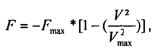
Par suite, le processeur 43 exécute des instructions mémorisées dans la mémoire principale 44 pour déterminer l'effort statique en temps réel à l'aide des relations suivantes donnant l'effort statique courant exercé sur une servocommande en fonction de la vitesse de déplacement courante V, à savoir à l'aide :
- de la première relation suivante lorsque la vitesse de déplacement courante est positive :

- de la deuxième relation suivante lorsque la vitesse de déplacement courante est négative :

- of the first following relation when the current speed of movement is positive:
- of the second following relation when the current speed of movement is negative:
On constate que la représentation graphique de ces première et deuxième relations présentent un premier segment associé à la première relation dans un quadrant positif Q1, et un deuxième segment associé à la deuxième relation dans un quadrant négatif Q2. On comprend qu'un segment est relatif à l'extension de la servocommande, alors qu'un autre segment est relatif à la rétraction de la servocommande.It can be seen that the graphical representation of these first and second relations has a first segment associated with the first relation in a positive quadrant Q1, and a second segment associated with the second relation in a negative quadrant Q2. It is understood that a segment is relative to the extension of the servocontrol, while another segment is relative to the retraction of the servocontrol.
De plus, selon la réalisation associée à la
Toutefois, la vitesse de déplacement maximale Vmax peut varier en fonction de la valeur courante de la section variable de cette ouverture.However, the maximum displacement speed Vmax may vary according to the current value of the variable section of this opening.
Selon un mode de réalisation préféré, à chaque valeur possible de la vitesse de déplacement maximale Vmax, correspond alors une équation permettant d'obtenir l'effort statique.According to a preferred embodiment, at each possible value of the maximum displacement speed Vmax, then corresponds to an equation making it possible to obtain the static force.
La
On constate, selon ce mode de réalisation préféré, la présence d'une pluralité de segments par quadrant Q1, Q2, chaque segment d'un quadrant correspondant à une ouverture d'une section donnée. On comprend que plus la section d'une ouverture est grande, plus la vitesse de déplacement maximale est importante.According to this preferred embodiment, there is the presence of a plurality of segments per quadrant Q1, Q2, each segment of a quadrant corresponding to an opening of a given section. It is understood that the larger the section of an opening, the greater the maximum displacement speed.
Ainsi, selon ce deuxième mode de réalisation, on détermine une valeur courante de la section variable de l'ouverture du distributeur hydraulique 30 alimentant en fluide l'espace interne.Thus, according to this second embodiment, a current value of the variable section of the opening of the
Par suite, on détermine la vitesse de déplacement maximale V max en temps réel à l'aide de l'équation suivante : 
En référence à la
Ce capteur d'ouverture 48 peut être un capteur de position du levier de commande 34 relié au calculateur par une liaison non représentée sur les figures, à savoir une liaison filaire ou sans fil.This opening
En fonction de la position du levier de commande, le processeur exécute des instructions de la mémoire principale pour en déduire la valeur courante S 1.Depending on the position of the control lever, the processor executes instructions from the main memory to deduce the current value S 1 .
De plus, le dispositif 40 inclut un premier capteur de pression 44 de la pression d'alimentation Pin relié au calculateur 42 par des liaisons filaires ou non filaires non représentées. De même, le dispositif 40 peut inclure au moins un deuxième capteur de pression 45 de la pression de sortie Pout relié au calculateur 42 par des liaisons filaires ou non filaires non représentées sur les figures, une pluralité de capteurs agencés dans chaque chambre d'extension 23 et de rétraction 24 du corps 21 par exemple.In addition, the
Le calculateur peut alors déterminer en temps réel la vitesse de déplacement maximale associée à une position donnée du distributeur hydraulique 40 à l'aide de l'équation programmée dans sa mémoire principale 44, pour en déduire l'effort statique exercé sur la servocommande.The computer can then determine in real time the maximum movement speed associated with a given position of the
Il est à noter que pour simplifier le dispositif 40, il est possible de considérer que la pression de sortie Pout est proportionnelle à la moitié de la pression d'entrée Pin selon un rapport de proportionnalité donné, voire égale à la moitié de la pression d'entrée Pin . Dès lors, il n'est pas nécessaire d'implémenter au moins un deuxième capteur de pression.It should be noted that to simplify the
De plus, pour augmenter la précision du dispositif 40, ce dispositif 40 peut inclure un capteur de température 47 du fluide alimentant le distributeur hydraulique 30.In addition, to increase the accuracy of the
A l'aide de cette température du fluide et d'équations adaptés, le processeur du calculateur 42 exécute des instructions pour déterminer le coefficient de perte de charge Cq et la masse volumique p en fonction de la température mesurée, à l'aide de moyens usuels de type bases de données, abaques ou équations par exemple.With the aid of this fluid temperature and appropriate equations, the processor of the
Enfin, le dispositif 40 peut comprendre un moyen d'alerte 46. Dès lors, on peut activer le moyen d'alerte 46 lorsque l'effort statique dépasse un seuil prédéterminé.Finally, the
Naturellement, la présente invention est sujette à de nombreuses variations quant à sa mise en oeuvre. Bien que plusieurs modes de réalisation aient été décrits, on comprend bien qu'il n'est pas concevable d'identifier de manière exhaustive tous les modes possibles. Il est bien sûr envisageable de remplacer un moyen décrit par un moyen équivalent sans sortir du cadre de la présente invention.Naturally, the present invention is subject to many variations as to its implementation. Although several embodiments have been described, it is well understood that it is not conceivable to exhaustively identify all the possible modes. It is of course conceivable to replace a means described by equivalent means without departing from the scope of the present invention.
Claims (8)
- Method for determining the static force developed by a servo-control (10) provided with an actuator (20) and a hydraulic distributor (30), said actuator (20) comprising at least one body (21) defining an inside space (22) and a sliding element (25) provided with a control piston (26) sliding in said inside space (22), said hydraulic distributor (30) feeding said inside space (22) with a fluid, characterised in that:- the relative instantaneous travel speed of said sliding element (25) relative to said body (21) of the servo-control (10) is determined,- said static force is determined with the help ofwhere "F" represents said static force developed by the servo-control (10), "F max" represents a predetermined maximum static force that can be developed by said servo-control (10) "V2" represents the instantaneous travel speed to the power of two,• the following first relationship when the instantaneous travel speed is positive:
 • the following second relationship when the instantaneous travel speed is negative:

- Method according to Claim 1,
characterised in that:- the instantaneous travel speed (V) of said sliding element (25) relative to said body (21) of the servo-control (10) is determined with the help of a sensor for measuring the travel speed (41),- with a computer (42) comprising a processor (43) and a main memory (44) storing instructions relating to said first relationship and to said second relationship, said static force is determined with the help of said first relationship and said second relationship by executing said instructions with said processor (43). - Method according to any one of Claims 1 to 2,
characterised in that said instantaneous travel speed (V) is determined in real time by determining a flow rate of said fluid, and then by dividing said flow rate by the area (S0) of a constant section of the piston. - Method according to any one of Claims 1 to 2,
characterised in that, with said hydraulic distributor (30) communicating with said inside space (22) via an opening (31) of variable section, said hydraulic distributor (30) comprising a movable restriction means (32) in order to adjust said variable section, an instantaneous value of the variable section of the hydraulic distributor (30) is determined and then the maximum travel speed V max is determined in real time with the help of the following equation:
where "Cq " represents a predetermined head loss coefficient of the hydraulic distributor (30), "S 1" represents an instantaneous value of the variable section, "ρ" represents the density of said fluid, "Pin " represents the feed pressure of the fluid entering said hydraulic distributor (30), "Pout " represents the outlet pressure leaving the hydraulic distributor, "S 0" represents the area of a constant section of said piston (26), and "*" represents the multiplication sign. - Method according to Claim 4,
characterised in that the maximum travel speed V max is determined in real time with the help of the equation by executing instructions with a processor (43) of a computer (42). - Method according to Claim 4,
characterised in that the outlet pressure (Pout ) is proportional to the inlet pressure (Pin ). - Method according to Claim 4,
characterised in that the temperature of said fluid is measured, said head loss coefficient (Cq ) and said density (ρ) being determined as a function of said temperature. - Method according to any one of Claims 1 to 7,
characterised in that a warning is triggered when said static force (F) exceeds a predetermined threshold.
Applications Claiming Priority (1)
| Application Number | Priority Date | Filing Date | Title |
|---|---|---|---|
| FR1101611A FR2975774B1 (en) | 2011-05-25 | 2011-05-25 | METHOD FOR DETERMINING THE STATIC EFFORT DEVELOPED BY A SERVOCOMMANDE |
Publications (2)
| Publication Number | Publication Date |
|---|---|
| EP2527660A1 EP2527660A1 (en) | 2012-11-28 |
| EP2527660B1 true EP2527660B1 (en) | 2014-01-08 |
Family
ID=46051645
Family Applications (1)
| Application Number | Title | Priority Date | Filing Date |
|---|---|---|---|
| EP12003792.4A Active EP2527660B1 (en) | 2011-05-25 | 2012-05-14 | Method for determining the static force developed by a servocontrol |
Country Status (5)
| Country | Link |
|---|---|
| US (1) | US9115735B2 (en) |
| EP (1) | EP2527660B1 (en) |
| KR (1) | KR101321115B1 (en) |
| CN (1) | CN102795334B (en) |
| FR (1) | FR2975774B1 (en) |
Families Citing this family (2)
| Publication number | Priority date | Publication date | Assignee | Title |
|---|---|---|---|---|
| FR2975774B1 (en) * | 2011-05-25 | 2014-01-17 | Eurocopter France | METHOD FOR DETERMINING THE STATIC EFFORT DEVELOPED BY A SERVOCOMMANDE |
| CN108088599A (en) * | 2017-12-01 | 2018-05-29 | 中国直升机设计研究所 | A kind of helicopter electromagnetic actuator power output variation characteristic test method |
Family Cites Families (18)
| Publication number | Priority date | Publication date | Assignee | Title |
|---|---|---|---|---|
| FR2236132B1 (en) * | 1973-07-03 | 1983-11-18 | Messier Hispano Sa | |
| US3892164A (en) | 1973-12-19 | 1975-07-01 | Mimik Limited | Servo control for machine tools |
| US4793188A (en) * | 1986-01-14 | 1988-12-27 | Texas Instruments Incorporated | Lubrication sensor apparatus |
| US5829335A (en) | 1993-05-11 | 1998-11-03 | Mannesmann Rexroth Gmbh | Control for hydraulic drive or actuator |
| DE4335403C1 (en) * | 1993-10-18 | 1994-12-15 | Karl Hehl | Hydraulic device |
| WO1996028660A1 (en) * | 1995-03-14 | 1996-09-19 | The Boeing Company | Aircraft hydraulic pump control system |
| GB9919814D0 (en) * | 1999-08-20 | 1999-10-27 | Dowty Boulton Paul Ltd | Transducer |
| DE10256923B4 (en) * | 2002-12-05 | 2013-10-24 | Liebherr-France S.A. | Method and device for motion damping of hydraulic cylinders of mobile machines |
| GB0328935D0 (en) * | 2003-12-12 | 2004-01-14 | Goodrich Actuation Systems Ltd | Hydraulic control valve |
| US7739058B2 (en) * | 2006-03-17 | 2010-06-15 | Mitsubishi Electric Corporation | Condition-monitoring device and switch-control device provided with the same |
| DE102006033487A1 (en) | 2006-07-19 | 2008-01-31 | Robert Bosch Gmbh | Method for supporting an overtaking process in a motor vehicle |
| DE102007007005B4 (en) | 2007-02-08 | 2021-12-02 | Robert Bosch Gmbh | Electro-hydraulic control arrangement |
| DE102007051857B3 (en) | 2007-10-30 | 2009-04-23 | Siemens Ag | Control device for position control of a hydraulic cylinder unit with linearization unit |
| WO2009124054A1 (en) * | 2008-03-31 | 2009-10-08 | Delta Technologies | System, device and associated methods for monitoring a physical condition or operating performance of a structure |
| WO2011014954A1 (en) | 2009-08-04 | 2011-02-10 | Depiak Industrial Technology Corporation | Fluid driven reciprocating linear motor |
| FR2962774B1 (en) * | 2010-07-19 | 2012-08-03 | Eurocopter France | SERVO CONTROL PROVIDED WITH A LIMIT DETECTION DEVICE |
| US9658627B2 (en) * | 2011-05-05 | 2017-05-23 | The Boeing Company | Detection of imminent control instability |
| FR2975774B1 (en) * | 2011-05-25 | 2014-01-17 | Eurocopter France | METHOD FOR DETERMINING THE STATIC EFFORT DEVELOPED BY A SERVOCOMMANDE |
-
2011
- 2011-05-25 FR FR1101611A patent/FR2975774B1/en not_active Expired - Fee Related
-
2012
- 2012-05-14 EP EP12003792.4A patent/EP2527660B1/en active Active
- 2012-05-22 US US13/477,342 patent/US9115735B2/en not_active Expired - Fee Related
- 2012-05-23 KR KR1020120055065A patent/KR101321115B1/en active IP Right Grant
- 2012-05-24 CN CN201210165512.4A patent/CN102795334B/en active Active
Also Published As
| Publication number | Publication date |
|---|---|
| FR2975774A1 (en) | 2012-11-30 |
| KR20120132378A (en) | 2012-12-05 |
| CN102795334B (en) | 2014-12-24 |
| KR101321115B1 (en) | 2013-10-23 |
| US20120303296A1 (en) | 2012-11-29 |
| EP2527660A1 (en) | 2012-11-28 |
| FR2975774B1 (en) | 2014-01-17 |
| US9115735B2 (en) | 2015-08-25 |
| CN102795334A (en) | 2012-11-28 |
Similar Documents
| Publication | Publication Date | Title |
|---|---|---|
| EP3421357B1 (en) | Landing gear provided with an on-board device for measuring the load of an aircraft, and aircraft | |
| EP2505502B1 (en) | Method and device to assist piloting of an aircraft, and aircraft | |
| EP2634447B1 (en) | An electric brake for an airacraft wheel, the brake including an electromechanical actuator fitted with a temperature sensor. | |
| EP3702269B1 (en) | A haptic alert mechanism for alerting an aircraft pilot, and an aircraft | |
| EP2623417B1 (en) | A method of managing a steering command for a steerable portion of aircraft landing gear | |
| EP3753844B1 (en) | Control handle and hybrid rotorcraft provided with a lift rotor and at least one propulsion rotor generating thrust | |
| CA3037781C (en) | Meshing process for two gear elements and drive device implementing such a process | |
| EP2527660B1 (en) | Method for determining the static force developed by a servocontrol | |
| EP3060929B1 (en) | Method and device for measuring the angle of attack and the sideslip of an aircraft | |
| FR3097527A1 (en) | Method of assisting in piloting a hybrid rotorcraft equipped with a lift rotor and at least one propellant rotor with propeller generating thrust | |
| EP3251955B1 (en) | A method and a device for assisting the piloting of an aircraft, and an aircraft | |
| EP3546792B1 (en) | A method of engaging two gear elements, and a drive device implementing such a method | |
| EP3771649B1 (en) | System for evaluating the clogging of a filter equipping an aircraft, aircraft comprising such an evaluation system and associated method | |
| EP3647192B1 (en) | Method and device for assisted piloting of a hybrid rotorcraft provided with a lift rotor and at least one propulsion rotor generating thrust | |
| EP2410188B1 (en) | Servoactuator with limit effort detection | |
| EP2446149B1 (en) | Device and method for positioning variable-geometry equipment for a turbomachine, using a relative-measurement jack | |
| EP3042847B1 (en) | A servo-control and an aircraft having such a servo-control | |
| EP3620687A1 (en) | Method for engaging two gear drive elements and drive device implementing such a method | |
| FR3045714A1 (en) | ADJUSTABLE KNIFE IN OPERATION, ROTOR OF ROTATING MACHINE, ROTATING MACHINE AND AIRCRAFT | |
| FR2681310A1 (en) | DEVICE FOR DETECTING THE ICING OF THE BLADES OF AN AIRCRAFT ROTOR. | |
| FR2954488A1 (en) | Method for determining deformation of aerofoil of aircraft i.e. helicopter, involves determining position of part of wing, and determining deformation of aerofoil by variation with attitude of aircraft | |
| EP4041628A1 (en) | System for controlling the cyclic setting of blades | |
| FR2986325A1 (en) | Method for detecting fluid leakage within servocontroller of helicopter-type rotorcraft, involves comparing temperature difference with threshold temperature to determine leakage, and generating alarm signal when leakage is detected | |
| FR3086638A1 (en) | MOTORIZED BALANCER LANDING AND AIRCRAFT | |
| FR2872484A1 (en) | Accessory driving device for aircraft, has two shafts integrated at one end with clearance which constitutes secondary connection with clearance to transmit movements and control efforts of pilot of aircraft to accessory in case of failure |
Legal Events
| Date | Code | Title | Description |
|---|---|---|---|
| PUAI | Public reference made under article 153(3) epc to a published international application that has entered the european phase |
Free format text: ORIGINAL CODE: 0009012 |
|
| AK | Designated contracting states |
Kind code of ref document: A1 Designated state(s): AL AT BE BG CH CY CZ DE DK EE ES FI FR GB GR HR HU IE IS IT LI LT LU LV MC MK MT NL NO PL PT RO RS SE SI SK SM TR |
|
| AX | Request for extension of the european patent |
Extension state: BA ME |
|
| 17P | Request for examination filed |
Effective date: 20130110 |
|
| RIC1 | Information provided on ipc code assigned before grant |
Ipc: F15B 15/28 20060101AFI20130429BHEP Ipc: F15B 20/00 20060101ALI20130429BHEP Ipc: G01L 1/00 20060101ALI20130429BHEP |
|
| GRAP | Despatch of communication of intention to grant a patent |
Free format text: ORIGINAL CODE: EPIDOSNIGR1 |
|
| INTG | Intention to grant announced |
Effective date: 20130815 |
|
| GRAS | Grant fee paid |
Free format text: ORIGINAL CODE: EPIDOSNIGR3 |
|
| GRAA | (expected) grant |
Free format text: ORIGINAL CODE: 0009210 |
|
| AK | Designated contracting states |
Kind code of ref document: B1 Designated state(s): AL AT BE BG CH CY CZ DE DK EE ES FI FR GB GR HR HU IE IS IT LI LT LU LV MC MK MT NL NO PL PT RO RS SE SI SK SM TR |
|
| REG | Reference to a national code |
Ref country code: GB Ref legal event code: FG4D Free format text: NOT ENGLISH |
|
| REG | Reference to a national code |
Ref country code: CH Ref legal event code: EP |
|
| REG | Reference to a national code |
Ref country code: IE Ref legal event code: FG4D Free format text: LANGUAGE OF EP DOCUMENT: FRENCH |
|
| REG | Reference to a national code |
Ref country code: AT Ref legal event code: REF Ref document number: 648932 Country of ref document: AT Kind code of ref document: T Effective date: 20140215 |
|
| REG | Reference to a national code |
Ref country code: DE Ref legal event code: R096 Ref document number: 602012000750 Country of ref document: DE Effective date: 20140220 |
|
| RAP2 | Party data changed (patent owner data changed or rights of a patent transferred) |
Owner name: AIRBUS HELICOPTERS |
|
| REG | Reference to a national code |
Ref country code: AT Ref legal event code: MK05 Ref document number: 648932 Country of ref document: AT Kind code of ref document: T Effective date: 20140108 |
|
| REG | Reference to a national code |
Ref country code: NL Ref legal event code: VDEP Effective date: 20140108 |
|
| REG | Reference to a national code |
Ref country code: LT Ref legal event code: MG4D |
|
| REG | Reference to a national code |
Ref country code: FR Ref legal event code: CD Owner name: AIRBUS HELICOPTERS, FR Effective date: 20140602 |
|
| PG25 | Lapsed in a contracting state [announced via postgrant information from national office to epo] |
Ref country code: IS Free format text: LAPSE BECAUSE OF FAILURE TO SUBMIT A TRANSLATION OF THE DESCRIPTION OR TO PAY THE FEE WITHIN THE PRESCRIBED TIME-LIMIT Effective date: 20140508 Ref country code: LT Free format text: LAPSE BECAUSE OF FAILURE TO SUBMIT A TRANSLATION OF THE DESCRIPTION OR TO PAY THE FEE WITHIN THE PRESCRIBED TIME-LIMIT Effective date: 20140108 Ref country code: NO Free format text: LAPSE BECAUSE OF FAILURE TO SUBMIT A TRANSLATION OF THE DESCRIPTION OR TO PAY THE FEE WITHIN THE PRESCRIBED TIME-LIMIT Effective date: 20140408 |
|
| PG25 | Lapsed in a contracting state [announced via postgrant information from national office to epo] |
Ref country code: NL Free format text: LAPSE BECAUSE OF FAILURE TO SUBMIT A TRANSLATION OF THE DESCRIPTION OR TO PAY THE FEE WITHIN THE PRESCRIBED TIME-LIMIT Effective date: 20140108 Ref country code: SE Free format text: LAPSE BECAUSE OF FAILURE TO SUBMIT A TRANSLATION OF THE DESCRIPTION OR TO PAY THE FEE WITHIN THE PRESCRIBED TIME-LIMIT Effective date: 20140108 Ref country code: CY Free format text: LAPSE BECAUSE OF FAILURE TO SUBMIT A TRANSLATION OF THE DESCRIPTION OR TO PAY THE FEE WITHIN THE PRESCRIBED TIME-LIMIT Effective date: 20140108 Ref country code: FI Free format text: LAPSE BECAUSE OF FAILURE TO SUBMIT A TRANSLATION OF THE DESCRIPTION OR TO PAY THE FEE WITHIN THE PRESCRIBED TIME-LIMIT Effective date: 20140108 Ref country code: AT Free format text: LAPSE BECAUSE OF FAILURE TO SUBMIT A TRANSLATION OF THE DESCRIPTION OR TO PAY THE FEE WITHIN THE PRESCRIBED TIME-LIMIT Effective date: 20140108 Ref country code: ES Free format text: LAPSE BECAUSE OF FAILURE TO SUBMIT A TRANSLATION OF THE DESCRIPTION OR TO PAY THE FEE WITHIN THE PRESCRIBED TIME-LIMIT Effective date: 20140108 Ref country code: PT Free format text: LAPSE BECAUSE OF FAILURE TO SUBMIT A TRANSLATION OF THE DESCRIPTION OR TO PAY THE FEE WITHIN THE PRESCRIBED TIME-LIMIT Effective date: 20140508 |
|
| PG25 | Lapsed in a contracting state [announced via postgrant information from national office to epo] |
Ref country code: HR Free format text: LAPSE BECAUSE OF FAILURE TO SUBMIT A TRANSLATION OF THE DESCRIPTION OR TO PAY THE FEE WITHIN THE PRESCRIBED TIME-LIMIT Effective date: 20140108 Ref country code: RS Free format text: LAPSE BECAUSE OF FAILURE TO SUBMIT A TRANSLATION OF THE DESCRIPTION OR TO PAY THE FEE WITHIN THE PRESCRIBED TIME-LIMIT Effective date: 20140108 Ref country code: LV Free format text: LAPSE BECAUSE OF FAILURE TO SUBMIT A TRANSLATION OF THE DESCRIPTION OR TO PAY THE FEE WITHIN THE PRESCRIBED TIME-LIMIT Effective date: 20140108 |
|
| REG | Reference to a national code |
Ref country code: DE Ref legal event code: R097 Ref document number: 602012000750 Country of ref document: DE |
|
| PG25 | Lapsed in a contracting state [announced via postgrant information from national office to epo] |
Ref country code: DK Free format text: LAPSE BECAUSE OF FAILURE TO SUBMIT A TRANSLATION OF THE DESCRIPTION OR TO PAY THE FEE WITHIN THE PRESCRIBED TIME-LIMIT Effective date: 20140108 Ref country code: EE Free format text: LAPSE BECAUSE OF FAILURE TO SUBMIT A TRANSLATION OF THE DESCRIPTION OR TO PAY THE FEE WITHIN THE PRESCRIBED TIME-LIMIT Effective date: 20140108 Ref country code: RO Free format text: LAPSE BECAUSE OF FAILURE TO SUBMIT A TRANSLATION OF THE DESCRIPTION OR TO PAY THE FEE WITHIN THE PRESCRIBED TIME-LIMIT Effective date: 20140108 Ref country code: CZ Free format text: LAPSE BECAUSE OF FAILURE TO SUBMIT A TRANSLATION OF THE DESCRIPTION OR TO PAY THE FEE WITHIN THE PRESCRIBED TIME-LIMIT Effective date: 20140108 |
|
| PLBE | No opposition filed within time limit |
Free format text: ORIGINAL CODE: 0009261 |
|
| STAA | Information on the status of an ep patent application or granted ep patent |
Free format text: STATUS: NO OPPOSITION FILED WITHIN TIME LIMIT |
|
| PG25 | Lapsed in a contracting state [announced via postgrant information from national office to epo] |
Ref country code: PL Free format text: LAPSE BECAUSE OF FAILURE TO SUBMIT A TRANSLATION OF THE DESCRIPTION OR TO PAY THE FEE WITHIN THE PRESCRIBED TIME-LIMIT Effective date: 20140108 Ref country code: SK Free format text: LAPSE BECAUSE OF FAILURE TO SUBMIT A TRANSLATION OF THE DESCRIPTION OR TO PAY THE FEE WITHIN THE PRESCRIBED TIME-LIMIT Effective date: 20140108 |
|
| REG | Reference to a national code |
Ref country code: DE Ref legal event code: R119 Ref document number: 602012000750 Country of ref document: DE |
|
| 26N | No opposition filed |
Effective date: 20141009 |
|
| PG25 | Lapsed in a contracting state [announced via postgrant information from national office to epo] |
Ref country code: LU Free format text: LAPSE BECAUSE OF FAILURE TO SUBMIT A TRANSLATION OF THE DESCRIPTION OR TO PAY THE FEE WITHIN THE PRESCRIBED TIME-LIMIT Effective date: 20140514 |
|
| REG | Reference to a national code |
Ref country code: DE Ref legal event code: R097 Ref document number: 602012000750 Country of ref document: DE Effective date: 20141009 |
|
| PG25 | Lapsed in a contracting state [announced via postgrant information from national office to epo] |
Ref country code: MC Free format text: LAPSE BECAUSE OF FAILURE TO SUBMIT A TRANSLATION OF THE DESCRIPTION OR TO PAY THE FEE WITHIN THE PRESCRIBED TIME-LIMIT Effective date: 20140108 |
|
| REG | Reference to a national code |
Ref country code: IE Ref legal event code: MM4A |
|
| REG | Reference to a national code |
Ref country code: DE Ref legal event code: R119 Ref document number: 602012000750 Country of ref document: DE Effective date: 20141202 |
|
| PG25 | Lapsed in a contracting state [announced via postgrant information from national office to epo] |
Ref country code: IE Free format text: LAPSE BECAUSE OF NON-PAYMENT OF DUE FEES Effective date: 20140514 Ref country code: DE Free format text: LAPSE BECAUSE OF NON-PAYMENT OF DUE FEES Effective date: 20141202 |
|
| PG25 | Lapsed in a contracting state [announced via postgrant information from national office to epo] |
Ref country code: SI Free format text: LAPSE BECAUSE OF FAILURE TO SUBMIT A TRANSLATION OF THE DESCRIPTION OR TO PAY THE FEE WITHIN THE PRESCRIBED TIME-LIMIT Effective date: 20140108 |
|
| REG | Reference to a national code |
Ref country code: CH Ref legal event code: PL |
|
| PG25 | Lapsed in a contracting state [announced via postgrant information from national office to epo] |
Ref country code: CH Free format text: LAPSE BECAUSE OF NON-PAYMENT OF DUE FEES Effective date: 20150531 Ref country code: LI Free format text: LAPSE BECAUSE OF NON-PAYMENT OF DUE FEES Effective date: 20150531 |
|
| PG25 | Lapsed in a contracting state [announced via postgrant information from national office to epo] |
Ref country code: MT Free format text: LAPSE BECAUSE OF FAILURE TO SUBMIT A TRANSLATION OF THE DESCRIPTION OR TO PAY THE FEE WITHIN THE PRESCRIBED TIME-LIMIT Effective date: 20140108 |
|
| PG25 | Lapsed in a contracting state [announced via postgrant information from national office to epo] |
Ref country code: SM Free format text: LAPSE BECAUSE OF FAILURE TO SUBMIT A TRANSLATION OF THE DESCRIPTION OR TO PAY THE FEE WITHIN THE PRESCRIBED TIME-LIMIT Effective date: 20140108 |
|
| REG | Reference to a national code |
Ref country code: FR Ref legal event code: PLFP Year of fee payment: 5 |
|
| PG25 | Lapsed in a contracting state [announced via postgrant information from national office to epo] |
Ref country code: GR Free format text: LAPSE BECAUSE OF FAILURE TO SUBMIT A TRANSLATION OF THE DESCRIPTION OR TO PAY THE FEE WITHIN THE PRESCRIBED TIME-LIMIT Effective date: 20140409 Ref country code: BG Free format text: LAPSE BECAUSE OF FAILURE TO SUBMIT A TRANSLATION OF THE DESCRIPTION OR TO PAY THE FEE WITHIN THE PRESCRIBED TIME-LIMIT Effective date: 20140108 |
|
| PG25 | Lapsed in a contracting state [announced via postgrant information from national office to epo] |
Ref country code: BE Free format text: LAPSE BECAUSE OF FAILURE TO SUBMIT A TRANSLATION OF THE DESCRIPTION OR TO PAY THE FEE WITHIN THE PRESCRIBED TIME-LIMIT Effective date: 20140531 Ref country code: TR Free format text: LAPSE BECAUSE OF FAILURE TO SUBMIT A TRANSLATION OF THE DESCRIPTION OR TO PAY THE FEE WITHIN THE PRESCRIBED TIME-LIMIT Effective date: 20140108 Ref country code: HU Free format text: LAPSE BECAUSE OF FAILURE TO SUBMIT A TRANSLATION OF THE DESCRIPTION OR TO PAY THE FEE WITHIN THE PRESCRIBED TIME-LIMIT; INVALID AB INITIO Effective date: 20120514 |
|
| REG | Reference to a national code |
Ref country code: FR Ref legal event code: PLFP Year of fee payment: 6 |
|
| REG | Reference to a national code |
Ref country code: FR Ref legal event code: PLFP Year of fee payment: 7 |
|
| PG25 | Lapsed in a contracting state [announced via postgrant information from national office to epo] |
Ref country code: MK Free format text: LAPSE BECAUSE OF FAILURE TO SUBMIT A TRANSLATION OF THE DESCRIPTION OR TO PAY THE FEE WITHIN THE PRESCRIBED TIME-LIMIT Effective date: 20140108 |
|
| PG25 | Lapsed in a contracting state [announced via postgrant information from national office to epo] |
Ref country code: AL Free format text: LAPSE BECAUSE OF FAILURE TO SUBMIT A TRANSLATION OF THE DESCRIPTION OR TO PAY THE FEE WITHIN THE PRESCRIBED TIME-LIMIT Effective date: 20140108 |
|
| P01 | Opt-out of the competence of the unified patent court (upc) registered |
Effective date: 20230530 |
|
| PGFP | Annual fee paid to national office [announced via postgrant information from national office to epo] |
Ref country code: IT Payment date: 20230526 Year of fee payment: 12 Ref country code: FR Payment date: 20230526 Year of fee payment: 12 |
|
| PGFP | Annual fee paid to national office [announced via postgrant information from national office to epo] |
Ref country code: GB Payment date: 20230524 Year of fee payment: 12 |