EP3309061A1 - Elektrisches steuerorgan, drehflügelflugzeug und verfahren - Google Patents
Elektrisches steuerorgan, drehflügelflugzeug und verfahren Download PDFInfo
- Publication number
- EP3309061A1 EP3309061A1 EP17192890.6A EP17192890A EP3309061A1 EP 3309061 A1 EP3309061 A1 EP 3309061A1 EP 17192890 A EP17192890 A EP 17192890A EP 3309061 A1 EP3309061 A1 EP 3309061A1
- Authority
- EP
- European Patent Office
- Prior art keywords
- measurement
- control device
- operating means
- aircraft
- rate
- Prior art date
- Legal status (The legal status is an assumption and is not a legal conclusion. Google has not performed a legal analysis and makes no representation as to the accuracy of the status listed.)
- Granted
Links
- 238000000034 method Methods 0.000 title claims description 18
- 238000005259 measurement Methods 0.000 claims abstract description 188
- 238000012545 processing Methods 0.000 claims abstract description 78
- 230000007935 neutral effect Effects 0.000 claims abstract description 34
- 230000008859 change Effects 0.000 claims description 35
- 230000004048 modification Effects 0.000 claims description 14
- 238000012986 modification Methods 0.000 claims description 14
- 238000006073 displacement reaction Methods 0.000 claims description 8
- 230000008569 process Effects 0.000 claims description 5
- 230000005355 Hall effect Effects 0.000 claims description 3
- 230000001419 dependent effect Effects 0.000 claims description 2
- 230000001141 propulsive effect Effects 0.000 claims description 2
- 239000003380 propellant Substances 0.000 claims 2
- 230000033001 locomotion Effects 0.000 description 16
- 230000006870 function Effects 0.000 description 13
- 230000005540 biological transmission Effects 0.000 description 7
- 125000004122 cyclic group Chemical group 0.000 description 6
- 230000009471 action Effects 0.000 description 5
- 230000007257 malfunction Effects 0.000 description 5
- 230000003287 optical effect Effects 0.000 description 5
- 102100038804 FK506-binding protein-like Human genes 0.000 description 4
- 101001031402 Homo sapiens FK506-binding protein-like Proteins 0.000 description 4
- 238000012544 monitoring process Methods 0.000 description 4
- 101100443272 Arabidopsis thaliana DIR2 gene Proteins 0.000 description 3
- 238000010586 diagram Methods 0.000 description 3
- 230000009977 dual effect Effects 0.000 description 3
- 238000001514 detection method Methods 0.000 description 2
- 230000009347 mechanical transmission Effects 0.000 description 2
- 230000000007 visual effect Effects 0.000 description 2
- RZVHIXYEVGDQDX-UHFFFAOYSA-N 9,10-anthraquinone Chemical compound C1=CC=C2C(=O)C3=CC=CC=C3C(=O)C2=C1 RZVHIXYEVGDQDX-UHFFFAOYSA-N 0.000 description 1
- 101100494427 Arabidopsis thaliana CYP90C1 gene Proteins 0.000 description 1
- 241000940835 Pales Species 0.000 description 1
- 206010033546 Pallor Diseases 0.000 description 1
- 101100176057 Saccharomyces cerevisiae (strain ATCC 204508 / S288c) ROT2 gene Proteins 0.000 description 1
- 101100478693 Saccharomyces cerevisiae (strain ATCC 204508 / S288c) STP22 gene Proteins 0.000 description 1
- 230000001427 coherent effect Effects 0.000 description 1
- 238000004891 communication Methods 0.000 description 1
- 230000008014 freezing Effects 0.000 description 1
- 238000007710 freezing Methods 0.000 description 1
- 238000004519 manufacturing process Methods 0.000 description 1
- 210000000056 organ Anatomy 0.000 description 1
- 230000009467 reduction Effects 0.000 description 1
- 230000001052 transient effect Effects 0.000 description 1
- 230000007704 transition Effects 0.000 description 1
- 230000002747 voluntary effect Effects 0.000 description 1
Images


Classifications
-
- B—PERFORMING OPERATIONS; TRANSPORTING
- B64—AIRCRAFT; AVIATION; COSMONAUTICS
- B64C—AEROPLANES; HELICOPTERS
- B64C13/00—Control systems or transmitting systems for actuating flying-control surfaces, lift-increasing flaps, air brakes, or spoilers
- B64C13/02—Initiating means
- B64C13/04—Initiating means actuated personally
- B64C13/042—Initiating means actuated personally operated by hand
- B64C13/0421—Initiating means actuated personally operated by hand control sticks for primary flight controls
-
- B—PERFORMING OPERATIONS; TRANSPORTING
- B64—AIRCRAFT; AVIATION; COSMONAUTICS
- B64C—AEROPLANES; HELICOPTERS
- B64C11/00—Propellers, e.g. of ducted type; Features common to propellers and rotors for rotorcraft
- B64C11/30—Blade pitch-changing mechanisms
-
- B—PERFORMING OPERATIONS; TRANSPORTING
- B64—AIRCRAFT; AVIATION; COSMONAUTICS
- B64C—AEROPLANES; HELICOPTERS
- B64C13/00—Control systems or transmitting systems for actuating flying-control surfaces, lift-increasing flaps, air brakes, or spoilers
- B64C13/02—Initiating means
- B64C13/04—Initiating means actuated personally
- B64C13/044—Initiating means actuated personally operated by feet, e.g. pedals
-
- B—PERFORMING OPERATIONS; TRANSPORTING
- B64—AIRCRAFT; AVIATION; COSMONAUTICS
- B64C—AEROPLANES; HELICOPTERS
- B64C13/00—Control systems or transmitting systems for actuating flying-control surfaces, lift-increasing flaps, air brakes, or spoilers
- B64C13/24—Transmitting means
- B64C13/26—Transmitting means without power amplification or where power amplification is irrelevant
- B64C13/28—Transmitting means without power amplification or where power amplification is irrelevant mechanical
- B64C13/341—Transmitting means without power amplification or where power amplification is irrelevant mechanical having duplication or stand-by provisions
-
- B—PERFORMING OPERATIONS; TRANSPORTING
- B64—AIRCRAFT; AVIATION; COSMONAUTICS
- B64C—AEROPLANES; HELICOPTERS
- B64C13/00—Control systems or transmitting systems for actuating flying-control surfaces, lift-increasing flaps, air brakes, or spoilers
- B64C13/24—Transmitting means
- B64C13/38—Transmitting means with power amplification
- B64C13/40—Transmitting means with power amplification using fluid pressure
- B64C13/42—Transmitting means with power amplification using fluid pressure having duplication or stand-by provisions
-
- B—PERFORMING OPERATIONS; TRANSPORTING
- B64—AIRCRAFT; AVIATION; COSMONAUTICS
- B64C—AEROPLANES; HELICOPTERS
- B64C13/00—Control systems or transmitting systems for actuating flying-control surfaces, lift-increasing flaps, air brakes, or spoilers
- B64C13/24—Transmitting means
- B64C13/38—Transmitting means with power amplification
- B64C13/50—Transmitting means with power amplification using electrical energy
- B64C13/505—Transmitting means with power amplification using electrical energy having duplication or stand-by provisions
-
- B—PERFORMING OPERATIONS; TRANSPORTING
- B64—AIRCRAFT; AVIATION; COSMONAUTICS
- B64C—AEROPLANES; HELICOPTERS
- B64C13/00—Control systems or transmitting systems for actuating flying-control surfaces, lift-increasing flaps, air brakes, or spoilers
- B64C13/24—Transmitting means
- B64C13/38—Transmitting means with power amplification
- B64C13/50—Transmitting means with power amplification using electrical energy
- B64C13/506—Transmitting means with power amplification using electrical energy overriding of personal controls; with automatic return to inoperative position
-
- B—PERFORMING OPERATIONS; TRANSPORTING
- B64—AIRCRAFT; AVIATION; COSMONAUTICS
- B64C—AEROPLANES; HELICOPTERS
- B64C27/00—Rotorcraft; Rotors peculiar thereto
- B64C27/22—Compound rotorcraft, i.e. aircraft using in flight the features of both aeroplane and rotorcraft
- B64C27/26—Compound rotorcraft, i.e. aircraft using in flight the features of both aeroplane and rotorcraft characterised by provision of fixed wings
-
- B—PERFORMING OPERATIONS; TRANSPORTING
- B64—AIRCRAFT; AVIATION; COSMONAUTICS
- B64C—AEROPLANES; HELICOPTERS
- B64C27/00—Rotorcraft; Rotors peculiar thereto
- B64C27/54—Mechanisms for controlling blade adjustment or movement relative to rotor head, e.g. lag-lead movement
- B64C27/56—Mechanisms for controlling blade adjustment or movement relative to rotor head, e.g. lag-lead movement characterised by the control initiating means, e.g. manually actuated
-
- B—PERFORMING OPERATIONS; TRANSPORTING
- B64—AIRCRAFT; AVIATION; COSMONAUTICS
- B64C—AEROPLANES; HELICOPTERS
- B64C27/00—Rotorcraft; Rotors peculiar thereto
- B64C27/82—Rotorcraft; Rotors peculiar thereto characterised by the provision of an auxiliary rotor or fluid-jet device for counter-balancing lifting rotor torque or changing direction of rotorcraft
-
- B—PERFORMING OPERATIONS; TRANSPORTING
- B64—AIRCRAFT; AVIATION; COSMONAUTICS
- B64D—EQUIPMENT FOR FITTING IN OR TO AIRCRAFT; FLIGHT SUITS; PARACHUTES; ARRANGEMENTS OR MOUNTING OF POWER PLANTS OR PROPULSION TRANSMISSIONS IN AIRCRAFT
- B64D31/00—Power plant control; Arrangement thereof
- B64D31/02—Initiating means
- B64D31/04—Initiating means actuated personally
Definitions
- the present invention relates to an electrical control member, a rotary wing aircraft comprising such a control member, and a method applied by the aircraft.
- a helicopter-type rotary wing aircraft comprises at least one main rotor which at least partially participates in the lift and propulsion of this aircraft.
- a system allows at least to control the yaw movement of the aircraft.
- a helicopter has three axes of control.
- a first axis is to use a first command to control the vector of the lift vector of the aircraft.
- a second axis is to use a second command to control the orientation of this lift vector, and
- a third axis is to use a third command to control the yaw motion of the aircraft.
- a helicopter may comprise a main rotor involved in its propulsion and lift.
- a helicopter may comprise an auxiliary rotor participating at least in the control of the yaw movement.
- a collective lever collectively controls the pitch of the main rotor blades to adjust the lift of the aircraft.
- a cyclic stick cyclically controls the pitch of the main rotor blades to adjust the orientation of the lift vector of the aircraft.
- a rudder adjusts collectively the pitch of the auxiliary rotor blades to control the yaw movement of the helicopter.
- a helicopter may comprise two main rotors, possibly coaxial.
- a collective lever can collectively control the pitch of the main rotor blades to adjust the lift of the aircraft.
- a cyclic stick can make it possible to control cyclically the pitch of the blades of the main rotors to adjust the orientation of the lift vector of the aircraft.
- a rudder can be used to adjust the torque exerted by at least one main rotor on the fuselage of the aircraft, to control the yaw movement of the aircraft through the application of different couples.
- hybrid Another type of rotary wing aircraft called “hybrid” for convenience includes at least one rotor that participates at least partially in the lift and propulsion of this aircraft.
- the aircraft comprises a device for controlling the yaw movement of the aircraft.
- This aircraft also includes a system capable of exercising, at least in the direction of advancement of the aircraft, a thrust called “additional thrust” for convenience. This additional thrust is described as “additional” insofar as this thrust is axially independent of the thrust exerted by the rotary wing.
- such a hybrid rotary wing aircraft comprises a fourth steering axis.
- This fourth control axis consists of using a fourth command to drive the additional thrust standard.
- a hybrid rotary wing aircraft may comprise a main rotor which at least partially participates in the lift and propulsion of this aircraft.
- this hybrid rotary wing aircraft comprises a propulsion system provided with two propellers participating at least partially in the propulsion of the aircraft and in the control of the yaw movement of this aircraft.
- a collective pitch lever may collectively control the pitch of the main rotor blades to adjust the lift vector standard of the aircraft.
- a cyclic stick can be used to cyclically control the pitch of the main rotor blades to adjust the orientation of the lift vector of the aircraft.
- a thrust control may allow a pilot to collectively adjust an average pitch of the propeller blades to control the additional thrust generated jointly by the propellers.
- a rudder can be used to adjust the distribution of this additional thrust between the two propellers to control the yaw movement of the aircraft through the application of different thrusts using the propellers.
- This rudder can for example be used to adjust a differential pitch, the pitch of the blades of a helix being for example equal to the sum of the average pitch and the half of the differential pitch, the pitch of the blades of the other helix being for example equal to the difference of the average pitch and the half of the differential pitch.
- Push control can take the form of an "all or nothing" command.
- this thrust command When the thrust control is maneuvered, this thrust command generates an order of increase or decrease of the average pitch of the propeller blades. This order is transmitted to actuators to change the pitch of the blades of the two propellers in the same way.
- an actuator is arranged on a mechanical transmission chain controlling a hydraulic distributor, the hydraulic distributor supplying a hydraulic cylinder capable of generating a movement of the blades of a propeller.
- a flight control independent of the thrust control can position the blades of the propellers in a predetermined position, especially during an autorotation flight phase.
- a mechanical emergency control can also be provided to enable the propellers to be controlled in the event of a malfunction of the thrust control.
- This mechanical control may comprise a mechanical lever capable of mechanically moving said mechanical transmission chain controlling a hydraulic distributor.
- the document FR 2984004 describes a rotary control device provided with a wheel, and a return device tending to return the knob to a neutral position.
- An indexing device keeps the wheel in at least one position relative to a support.
- the control device further comprises a printed circuit equipped with a sensor for detecting a movement of the wheel.
- This document FR 2984004 is remote from the invention by not relating to the control of an additional thrust of a hybrid rotary wing aircraft.
- the document WO 2015/181525 describes an electrical control device provided with an operating means and a support.
- the controller includes a sensor for measuring a current position of the operating means and a force sensor.
- the document US 2011/140690 describes an electrical control device provided with an operating means and a support.
- the controller includes a sensor for measuring a current angular position of the operating means.
- the present invention therefore aims to provide an innovative control device that can be used to control a thrust of an aircraft.
- the invention therefore relates to an electrical control device provided with an operating means and a support, the operating means being movable relative to this support, the operating means being intended to be displaced with respect to the support by a individual, the electrical control device comprising a first measuring system which performs a first measurement of a current position of the operating means relative to a neutral position.
- the electrical control device comprises a second measuring system which performs a second measurement of the current position, the first measuring system and the second measuring system being independent and dissimilar, the control device comprising a processing unit comparing the first measurement and the second measurement for generating a control signal according to said current position, the processing unit considering that the operating means is in the neutral position when the first measurement and the second measurement do not correspond to the same position of the means. maneuvering.
- an audible and / or visual fault detection alert can be emitted by the processing unit.
- maneuver means means an organ that can be maneuvered by an individual.
- this expression designates a movable member of an electrical switch.
- the operating means may comprise a wheel movable in rotation relative to the support, a lever ...
- first measure and second measure represent data which vary according to the position of the means of maneuver relative to a reference. For example, the angular position of a wheel relative to a reference is measured through the first measurement and the second measurement. Therefore, for two different positions of the operating means, the first measurement and the second measurement must each take two different values.
- independent and dissimilar means that the first measurement system and the second measurement system generate signals of different natures, although both are relative to the position of the operating means.
- the first measurement and the second measurement represent different data, although both are representative of the position of the operating means.
- the first measurement retranscribes the position of the operating means in the form of an electric current having a certain electrical voltage
- the second measurement retranscribes the position of the operating means in the form of a binary value.
- the invention does not implement a single measuring system measuring the position of the operating means.
- the electrical control device comprises two dissimilar measuring systems which each measure the position of the operating means.
- the first measurement and the second measurement can go through two different paths up to the processing unit.
- the first measurement and the second measurement are compared to verify that the measurement systems are working properly.
- each measure can be associated with an order to give. If the first measurement and the second measurement relate to two different orders, the processing unit deduces the presence of an inconsistency.
- each value of the first measurement can be associated with a theoretical value that the second measurement should reach.
- the processing unit determines whether the second measurement corresponds to the stored theoretical value. If not, the processing unit deduces the presence of an inconsistency.
- the processing unit deduces that a measuring system is down. Therefore, the processing unit generates the predetermined and stored control signal corresponding to the neutral position of the operating means. The processing unit therefore ignores the information given by the first measurement system and the second measurement system.
- a state of invalidity can also be generated to determine whether a signal corresponding to the neutral position has been sent following an inconsistency or following the positioning of the operating means in this neutral position.
- the processing unit can generate a control signal corresponding to the last coherent measurement.
- the processing unit In the absence of inconsistency, the processing unit generates the predetermined and stored control signal corresponding to the first measurement and the second measurement.
- the electrical control device can control an important function of an aircraft, such as a longitudinal thrust on a hybrid aircraft with rotary wing.
- the first measurement and the second measurement can be taken into account for controlling actuators acting on the longitudinal thrust of an aircraft according to a command type architecture (COM) and monitoring (MON) where the measurements developed by two independent channels must be in agreement for the action to be performed, this or these actuators freezing their actions in case of dissimilarity between the measurements received.
- COM command type architecture
- MON monitoring
- the electrical control device may comprise one or more of the following features.
- the first measurement system may be a means delivering the first measurement in the form of a first analog type signal
- the second measurement system being a means delivering the second measurement in the form of a second digital type signal.
- the first measurement system can thus emit an analog signal. Therefore, the first measurement may be in the form of an electric current having a voltage that varies depending on the position of the operating means, for example in a range from 0 to 12 volts.
- the second measurement system delivers a digital signal.
- the second measurement can thus be a digital measurement, for example of the "reflected binary" type.
- the second measurement system can indeed apply a Gray code.
- the first measurement system may comprise a potentiometer or a Hall effect sensor or an active electrical displacement displacement sensor, the first measurement being expressed as a first signal having an electrical voltage dependent on said current position.
- RVDT An active electrical displacement sensor is known by the acronym "RVDT" which corresponds to the English expression “Rotary Variable Differential Transformer”.
- the second measurement system may comprise a rotary wheel integral with the actuating means and a processing system cooperating with the coding wheel to determine a current binary value corresponding to said current position, the second measurement being expressed in the form a second signal comprising said binary value.
- the treatment system may be a conventional optical or magnetic system.
- An encoder wheel is a pure binary code generator. An encoder wheel makes it possible to send back a digital signal which depends on the displacement effected by the encoder wheel.
- the encoder wheel is in the form of a perforated wheel.
- the treatment system generates a light beam that illuminates a measuring face of the wheel. Depending on the position of the wheel, the light beam passes through the wheel through a perforation and then reaches a sensor, or stops against the measuring face of the wheel. When a sensor detects the presence of a beam, this sensor emits an electrical signal.
- three beams and three sensors are optionally used.
- a digital signal comprising a number of different bits is possible, and for example a four-bit digital signal.
- Gray's code also known as "reflected binary” allows only one bit to be changed when a number is increased by one to avoid potentially awkward transient states.
- the electrical control device may comprise a return system tending to return the operating means in the neutral position.
- the return system may comprise springs or miniature gas cylinders associated with mechanical stops preventing their action beyond the return to the neutral position.
- This return system tends to mechanically reminder and maintain in the neutral position the operating means.
- this individual exerts a force against the force exerted by the return system.
- this individual releases the operating means, the return system moves the operating means to its neutral position.
- the return system may comprise a first spring and a second spring which are respectively provided with a first movable end and a second movable end, said actuating means comprising an element arranged circumferentially between the first movable end and the first movable end.
- second mobile end said return system comprising a stop, said first spring tending to move circumferentially in a first direction said first end movable against the stop to position the operating member in the neutral position, said second spring tending to move circumferentially in a second direction said second end movable against the stop to position the operating member in the neutral position.
- the electrical control device may comprise a retaining system tending to retain said operating means in at least one so-called "indexed" position relative to the support.
- the restraint system may take the form of a notching system, for example provided with a ball and an elastic member.
- the restraint system can therefore be of the type described in the document FR 2984004 .
- the restraint system may be a friction system.
- a friction system comprises a member rubbing against the actuating means to tend to retain the operating means in a position.
- the restraint system can define a plurality of switching positions in which the operating means can be located relative to the support, each position theoretically generating different measurements for both the first measurement and the second measurement.
- the restraint system tends to retain the operating means in each position.
- the return system provides a return force on the operating means greater than the holding force exerted by the restraint system.
- the restraint system makes it possible to maintain the position of the operating means in the event of failure of the reminder system.
- the malfunction of the mechanical return system in the neutral position therefore does not entail the inadvertent rotation of the operating means, even in the presence of vibrations and in particular in an aircraft cockpit, because of the action of the restraint system.
- the electrical control device may have a first assembly provided with the support as well as the operating means and the first measurement system and the second measurement system, said processing unit being fixed to the first assembly while being integral with the support, said processing unit being intended to be connected to at least one physically independent computer of the first set, said processing unit transmitting to the computer said control signal, said control signal being relative to a parameter whose value is established according to a measured position of the operating means when the first measurement and the second measurement each correspond to said measured position or said neutral position when the first measurement and the second measurement do not correspond to the same position of the operating means.
- the control signal may also include validity information. Therefore, the control signal makes it possible to indicate whether an order relative to said neutral position is a voluntary order or an order resulting in an inconsistency.
- the operating means, the first measuring system, the second measuring system and the processing unit comparing the measurements are integrated in the same equipment capable of transmitting a control command to at least one computer.
- an autopilot system by at least one bus, for example of the CAN type.
- the device electrical control is then easily integrable in an aircraft for example.
- CAN corresponds to the English expression "Controller Area Network” and refers to a particular type of bus.
- the processing unit may for example take the form of a programmable logic circuit.
- a programmable logic circuit is a logic integrated circuit that can be reprogrammed after its manufacture. Such a network comprises numerous elementary logic cells and freely connectable logic flip-flops.
- a programmable logic circuit may take the form of an electronic component known by the acronym "FPGA” corresponding to the English expression "field-programmable gate array”.
- the processing unit generates and transmits the control signal to the computer of an autopilot system for controlling a propulsion system of an aircraft.
- the electrical control device has a first assembly provided with the support as well as the operating means and the first measurement system and the second measurement system, said processing unit not being fixed to the first set, the processing unit being offset with respect to this first set, said processing unit being connected to the first set possibly by at least one bus, said bus being connected to the first measuring system and to the second measuring system, said transmitting processing unit to the computer said control signal, said control signal being relative to a parameter whose value is established as a function of a measured position of the operating means when the first measurement and the second measurement each correspond to said measured position or said position neutral when the first measurement and the second measurement do not correspond to the same position of the operating means.
- the operating means, the first measuring system, the second measurement system are integrated in the same equipment.
- This equipment is then connected to a remote processing unit, for example by a CAN bus or wired connections.
- the processing unit is an integral part of an autopilot system that controls a propulsion system of an aircraft.
- the invention in addition to an electrical control device, relates to an aircraft provided with at least one main rotor participating at least partially in the lift of the aircraft, this aircraft comprising at least one propulsion system separate from the main rotor, the propulsion system generating a thrust called "additional thrust" to at least participate in the progress of the aircraft.
- This aircraft comprises an electrical control device according to the invention, the electrical control device being connected to the propulsion system to at least partially control said additional thrust, the control signal requiring a rate of change of said additional thrust transmitted to the propulsion system.
- the operating means is mounted on a collective lever collectively controlling the pitch of the main rotor blades.
- the propulsion system may comprise at least one propeller, and a pitch modification system modifying the pitch of the blades of this propeller.
- the processing unit can be connected to an automatic control system of the propulsion system, or can be a part of such an automatic control system by being connected to the pitch modification system which acts on the pitch of the blades of the propellers.
- the maneuvering of the operating means does not induce the generation of an on-off command merely controlling an increase or a reduction in the additional thrust.
- the operation of the operating means induces the generation of a control signal controlling a rate of change of this additional thrust.
- the rate of change can be directly a rate of variation of the additional thrust expressed for example expressed in watts per second, or a rate of variation of the pitch of the blades of the propellers generating said thrust expressed in degrees of steps per second.
- This electrical control device thus makes it possible to finely control the speed of variation of the additional thrust.
- the aircraft may further include one or more of the following features.
- the propulsion system comprising at least one propeller comprising a plurality of blades with variable pitch
- the propulsion system comprising a pitch modification system for modifying said pitch
- the processing unit is connected to the modification system of the pitch.
- the aircraft may comprise an emergency electric actuator connected to the propulsion system, to require a zero variation rate of the additional thrust or to position the average pitch of the propeller blades in a predetermined position.
- the positioning of the propeller blades in a refuge position optimizes the pilot's workload.
- This emergency electric actuator can take precedence over the electrical control device and is independent of the operating means, this operating means being inhibited when the emergency operating maneuver is operated.
- a mechanical device for protecting the operating means can be applied.
- An avionics command can also be used to uninhibit the function.
- the emergency electric actuator may be connected to a computer communicating with the processing unit, or to the processing unit.
- the emergency electric actuator can be solicited during autorotation flight phases, or in case of seizure of the operating means.
- the implementation of the emergency electric actuator makes it possible to surpass the command received from this operating means and to impose a return to a refuge thrust control position.
- the aircraft may include a mechanical emergency maneuvering member connected to the propulsion system.
- this emergency mechanical maneuvering member takes the form of a lever acting on a power transmission chain connected to a servocontrol driving the thrust additional, for example by controlling the pitch of the blades of a propeller.
- the invention further provides a method for controlling a propulsion system of an aircraft.
- a visual or audible alarm can be issued by an alarm system.
- This method may further include one or more of the following steps.
- the method may compare the first measurement with a theoretical value of the second measurement.
- the second measurement should have a binary value of 001, 011, 010, 110, 111, 101, 100, respectively.
- the rate of change is considered to be nil.
- the rate of change is equal to the rate of change corresponding to the value of the first or second measure.
- the rate of change is equal to the rate of change corresponding to the value of the first measurement, the second measurement being used to monitor the system.
- the processing unit can therefore apply at least one law stored in the processing unit to compare the first measurement and the second measured.
- a law can take the form of one or more mathematical relationships or a table of values for example.
- the method may comprise a step of positioning an average pitch of the blades of each propeller in a predetermined position when an emergency electrical operating member is maneuvered by a pilot.
- the propulsion system may comprise at least one propeller comprising a plurality of blades with variable pitch
- said propulsion system may comprise a pitch modification system for modifying said variable pitch
- said rate of variation is a variation rate of said pitch not said blades of the helix
- said method comprising a step of modifying said pitch by applying said rate of variation of said pitch.
- the figure 1 has an electrical control device 1.
- This electrical control device 1 is provided with a support 2 carrying a means of maneuver 3.
- the operating means 3 is connected to the support 2 by a fastening system conferring a freedom of movement by means of maneuvering 3 with respect to the support 2 .
- the operating means 3 comprises a wheel movable in rotation about an axis of maneuver AX which is stationary relative to the support 2.
- the fastening system can then take the form of a rod 200 secured to the wheel and carried by bearings integral with the support 2
- Such a wheel may comprise a circumference provided with gripping means to promote its movement by a manual action of an individual.
- the wheel can be of the document type FR 2984004 .
- the electrical control device 1 may be provided with a return system 4.
- a return system 4 has the function of tending to return the operating means 3 in a reference position called "POS1 neutral position".
- Such a return system 4 may for example comprise at least one spring 5 or at least one gas cylinder.
- the figure 2 illustrates a rotational maneuvering means 3.
- This operating means 3 comprises an element 300 wedged circumferentially between two mobile ends of two springs 501, 502 of the return system.
- a first spring 501 extends in a first direction DIR1 on an arc of a circle between a seat 250 secured to the support 2 to a first movable end 503.
- the second spring 502 extends in a second direction DIR2, opposed to first direction DIR1, on an arc of a circle between a seat 250 secured to the support 2 to a second mobile end 503.
- the return system 4 comprises a stop 505.
- the stop 505 comprises a first contact face adapted to block the extension in the first direction DIR1 of the first spring 501 by interference with the first movable end 503, and a second face contact block adapted to block the extension of the second spring 502 in the second direction DIR2 by interference with the second mobile end 504.
- the stop takes for example the shape of a shoulder of the support 2.
- This stop is further located at the right of the position that must reach the element 300 in the neutral position.
- the element 3 tends to compress the first spring 501.
- the first spring 501 stretches and repositions the operating member 3 in its neutral position, even in the event of a fault in the second spring 502 since the rotation of the operating member stops when the first movable end 503 reaches the stop 505.
- the element 3 tends to compress the second spring 502.
- the second spring 502 stretches and repositions the operating member 3 in its neutral position, even in the event of a fault in the first spring 501 since the rotation of the operating member 3 stops when the second mobile end 504 reaches the stop 505.
- the electric control device 1 may comprise a retaining system 6.
- This retaining system 6 has the function of tending to retain the operating means 3 in at least one so-called "indexed" position relative to the support 2.
- the operating means 3 can be positioned in a plurality of indexed switching positions distinct and different from the neutral position. The restraint system 6 then tends to maintain the operating means 3 in each switching position.
- an individual then moves the operating means 3 from the neutral position POS1 to a current position POS2 to give an order to a system, such as a propulsion system of an aircraft.
- the actuating means 3 then performs according to this example a rotation of an angle 100 around its operating axis AX.
- the angular position of the operating means 3 relative to the neutral position conditions the order given by the electrical control device 1 to a system.
- the return system 4 When the individual releases the operating means 3, the return system 4 returns the operating means 3 in the neutral position POS1. In the event of a malfunction of the return system, the restraint system tends to maintain the operating means in the position reached.
- the restraint system 6 may take the form of a friction system.
- a friction system may for example comprise an elastic member 7 tending to press a shoe 8 against an integral member in rotation with the operating means 3
- a notch system may be envisaged, such as a system comprising a ball and housings formed in a ring of the actuating means 3. An elastic member then tends to position a ball in a housing.
- the electrical control device 1 comprises two measuring means each measuring the position of the operating means.
- the electrical control device 1 comprises a first measurement system 10 which makes a first measurement representing the current position of the operating means 3.
- This first measurement system 10 is fixed to the support 2.
- the electrical control device 1 comprises a second measurement system 20 which makes a second measurement also representing this current position POS2.
- the first measurement system 10 and the second measurement system 20 are independent and dissimilar. Each measuring system therefore performs a measurement independently of the other measurement system.
- the first measurement system 10 is a means delivering the first measurement in the form of a first analogue type signal S1.
- Such a first measurement system 10 comprises according to the figure 1 a potentiometer 11 integrated in an electronic circuit 12.
- a displacement of the operating means 3 induces a variation of the resistance of the potentiometer 11. Therefore, the electronic circuit 12 delivers a first measurement M1 taking the form of a first electrical signal S1 having an electrical voltage depending on the position of the operating means 3.
- the first measurement M1 has the form of a first signal S1 having a voltage between 10.285 and 12 volts, 8.571 and 10. 285 volts, 6.857 and 8.571 volts, 5.142 and 6.857 volts, 3.428 and 5.142 volts, 1.714 and 3.428 volts, or between 0 and 1.714 volts depending on the position of the operating means 3 and therefore the position of the movable terminal of the potentiometer 11.
- the first measurement system may comprise a hall effect sensor or an active electrical RVDT rotation displacement sensor.
- the second measurement system 20 can deliver the second measurement M2 in the form of a second signal S2 that is not analog but digital.
- This second measurement system 20 is fixed to the support 2.
- the second measurement system 20 comprises an encoder wheel 21.
- the second measurement system 20 comprises a processing system 22 which cooperates with said encoder wheel 21 to determine a current bit value corresponding to said current position POS2.
- the encoder wheel 21 is integral in rotation with the operating means 3.
- the encoder wheel can take the form of a body of a knob of the operating means. This body may include angular perforations to generate a binary value.
- the processing system may comprise optical beam generators 23, 24, a sensor 25, 26 by an optical beam generator 23, 24, and a computing unit 27.
- figure 1 illustrates two optical beam generators. Nevertheless, the processing system includes an optical beam generator per bit of the signal to be produced.
- the processing system can assign the value 1 to the corresponding bit of the second measurement. Conversely, if no perforation is in front of a beam and does not reach a sensor, the processing system can assign the value 0 to the corresponding bit.
- the second measurement M2 has the form of a second signal S2 having a 3-bit binary value respectively equal to 001, 011, 010, 110, 111, 101, 100 as a function of the position of the operating means 3.
- the electrical control device 1 comprises a processing unit 30.
- This processing unit 30 may comprise an input 31 receiving the first signal S1 and the second signal S2 respectively carrying the first measurement M1 and the second measurement M2.
- processing unit 30 may comprise at least one output for transmitting a control signal ORD to a system.
- processing unit 30 may for example comprise a processor 32 executing instructions stored on a memory 33.
- processing unit may comprise an integrated circuit, a programmable system or a logic circuit, these examples not limiting the scope given to the term "processing unit".
- the processing unit 30 has the function of comparing the first measurement M1 and the second measurement M2 to generate an ORD command signal.
- the processing unit 30 estimates that the operating means 3 is in the neutral POS1 position when the first measurement and the second measurement do not correspond to the same position of the operating means, possibly to a threshold tolerance close. The processing unit then generates a predetermined ORD command signal corresponding in particular to this neutral position.
- the processing unit then generates a predetermined ORD command signal corresponding in particular to this particular position.
- the processing unit is located outside a first assembly provided with the support 2 as well as the operating means 3 and the first measuring system 10 and the second measuring system 20.
- the processing unit 30 is not fixed to the support 2.
- the processing unit is therefore deported compared to the first together.
- the first measurement system 10 and the second measurement system 20 are for example connected to at least one bus 36 opening in particular to the processing unit 30.
- a bus 36 may be a CAN bus.
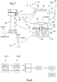
- the processing unit 30 is a part of a computer 86 of an automatic control system controlling the pitch of the blades 83 of at least one propeller 800.
- the first measuring system 10 and the second measuring system 20 are for example connected to a plurality of processing units 30.
- This figure 4 indeed has an architecture provided with two control device 151, 152 for example for a driver and a co-pilot respectively.
- Each control device comprises a first measuring means 10, a second measuring means 20 and a processing unit 30.
- a processing unit may comprise a calculator.
- such a calculator may be a dual calculator that includes two channels.
- Each of the channels includes its own microprocessor.
- One of the two channels can be used to generate the COM control that can be inhibited due to the detection of inconsistency through the communication of the first channel and the second channel.
- each measurement means 10, 20 is connected to each processing unit by two links.
- the links shown are wired links, but may include buses and in particular CAN buses.
- the processing units can further be connected to each other.
- the processing unit 30 is a part of the first set being fixed to the support 2.
- the processing unit 30 takes the form of an FPGA logic circuit.
- the processing unit 30 is thus connected to the first measurement system 10 and to the second measurement system 20.
- the processing unit 30 can be connected to the system to be controlled for example by at least one bus 35, such as a CAN bus.
- the processing unit 30 is connected by at least one CAN bus to at least one computer 86 of an automatic control system controlling the pitch of the blades 83 of at least one propeller 800.
- the processing unit 30 can be connected by two CAN buses to two computers 86, each computer cooperating with a monitoring unit.
- the processing unit 30 can also be connected by two channels to a dual computer 86. Monitoring, even if possible between two computers of a duplex architecture, can be done between two dual channels of the same computer.
- the processing unit transmits a control signal via each bus 35 to each computer 86.
- the processing unit can also transmit the first measurement and the second measurement to this computer, or even the result of the comparison made.
- the computer can verify that the command signal ORD issued is correct by performing the same comparison as the processing unit.
- the electric control device 1 can be arranged on a rotary wing aircraft, namely a rotorcraft 50.
- the rotorcraft 50 has a fuselage 52.
- the fuselage 52 extends longitudinally from a tail 54 to a nose 53 along an AXROL roll axis.
- the fuselage extends transversely from a first side, said "left flank 56" for convenience, to a second side, said "right side 55" by convenience, along a pitch axis AXTANG.
- the fuselage extends in elevation from a lower surface 58 to an upper surface 57 along an AXLAC yaw axis.
- the AXROL roll axis and the AXLAC yaw axis together define a vertical anteroposterior plane of symmetry of the rotorcraft 1.
- a landing gear can project down from the lower surface 58 of the fuselage.
- the rotorcraft comprises a rotary wing 60 comprising at least one main rotor 61.
- This main rotor 61 overhangs the upper surface 57 of the fuselage 52.
- the main rotor 61 is provided with a plurality of blades 62 connected for example to a hub 63. blades 62 are called “main blades" for convenience.
- the main rotor rotates about an axis called "AXROT main axis of rotation" to participate at least partially in the lift or propulsion of the rotorcraft.
- This main axis of rotation can be stationary relative to the fuselage 52.
- the rotorcraft 1 may include a propulsion system 80 providing additional longitudinal thrust P to participate in the movement of this rotorcraft.
- the propulsion system 80 may tend to propel or tow the rotorcraft.
- This propulsion system 80 may comprise at least one propeller 800 comprising a plurality of blades 83 with variable pitch.
- the rotorcraft then has a lift surface 70 which extends substantially transversely on either side of the fuselage.
- This lifting surface 70 may for example comprise a left half-wing 71 extending from left flank 56 and right half-wing 72 extending from right flank 55.
- the lifting surface then carries a propeller 800 called “first propeller 81" and a propeller 800 called “second helix 82".
- first propeller 81 a propeller 800
- second helix 82 a propeller 800
- the left half-wing 71 carries the first propeller 81
- the right half-wing 72 carries the second propeller 82.
- the first propeller 81 and the second propeller 82 are arranged transversely on either side of the fuselage 52 .
- Each helix produces a thrust P1, P2 jointly generating the additional thrust P.
- the first thrust P1 generated by the first helix 81 may differ from the second thrust P2 generated by the second helix 82 for controlling the yaw movement of the rotorcraft.
- the rotorcraft 1 includes a power plant 75 for moving the first propeller 81, the second propeller 82 and the main rotor 60.
- Such a power plant 75 may comprise at least one motor 76 and a mechanical chain connecting the motor to the first propeller 81 as well as to the second propeller 82 and to the main rotor 60.
- the mechanical chain includes a power transmission box 77 provided with a rotor mast driving the main rotor in rotation.
- this transmission can be connected to a first power transmission chain 78 rotating the first propeller 81.
- this transmission can be connected to a second power transmission chain 79 driving in rotation the second helix 82.
- the rotorcraft 50 has multiple flight controls to control the movement of this rotorcraft.
- the pitch of the main rotor blades can be changed collectively and cyclically.
- the rotorcraft comprises a set of cyclic plates 65 provided with a non-rotating plate 66 and a turntable 67.
- the non-rotating plate 66 is connected to at least three actuators called "main actuators 69" of the servo-controlled type.
- the turntable 67 is connected to each blade 62 of the main rotor by respectively a pitch rod 68.
- the rotorcraft may comprise a collective lever 91.
- This collective lever 91 can rotate ROT 1 about an AXBASCU tilting axis to drive the main actuators in the same way.
- the rotorcraft may comprise a cyclic stick 92.
- This cyclic stick 92 can rotate ROT2 about a first axis and rotate ROT3 about a second axis to drive the main actuators differently to control the rotation. plate of the rotorcraft.
- the pitch of the blades 83 of each propeller 800 can be modified by a pitch modification system 850.
- a pitch modification system 850 of a propeller may comprise a hydraulic distributor 84 supplying a hydraulic jack.
- This jack can be arranged in a hub of the propeller by a long perforated shaft.
- This hydraulic distributor 84 can be controlled by a power transmission chain including an electric jack 85 by example.
- This electric jack can be controlled by a computer 86.
- a rudder 93 can communicate with the computer 86, to control the yaw movement of the aircraft through a thrust difference between the first thrust exerted by the first propeller and the second thrust exerted by the second propeller.
- an electric control device 1 can be implemented.
- the operating means 3 is arranged on the collective lever 91.
- the control signal emitted by the electrical control device 1 may be a control signal of a rate of change of the additional thrust.
- the electric control device 1 requires the variation of the additional thrust in a negative or positive rate of change.
- the computer 86 then orders the pitch modification systems 850 of the propellers to modify the pitch of the propeller blades according to this rate of variation.
- the computer applies at least one mathematical relationship or solicits a database to generate the pitch modification orders of the propeller blades corresponding to the rate of change of pitch required by the electrical control device 1.
- the positioning of the pitch of the propellers can be enslaved via, on the one hand, the generation of a command transmitted to the computer 86 and, on the other hand, of a position sensor measuring information relative to the pitch of a blade .
- a position sensor can be connected to the computer 86.
- the sensor of position can be and arranged closer to the blades, for example at a hydraulic distributor 84.
- the computer 86 then controls the electric cylinder 85 to comply with the command received with respect to a feedback given by the sensor of position.
- the aircraft 50 may comprise an emergency electrical operating member 40 connected to the propulsion system 80.
- this emergency electrical operating member 40 takes the form of a push button connected to the computer 86.
- the aircraft 50 may comprise a mechanical emergency maneuvering member 45 connected to the propulsion system.
- a mechanical emergency maneuvering member 45 may comprise a lever displacing the electric jack 85 for example.
- the figure 8 illustrates the process implemented by this aircraft.
- an individual can maneuver the operating means 3 to generate a change in the additional thrust.
- the first measurement system During a first measurement step STP11, the first measurement system generates the first measurement M1. During a second measurement step STP12, the second measurement system generates the second measurement M2.
- a comparison step STP2 the first measurement and the second measurement are compared to each other.
- a first rate of variation relating to a variation of the additional thrust corresponding to the first measurement, is determined using a first law giving said first rate of change according to the first measurement.
- a second rate of variation relating to a variation of the additional thrust corresponding to the second measurement, is determined by using a second law giving said second rate of variation as a function of the second measure.
- the comparison is made by comparing the first rate of change and the second rate of change during a comparison phase STP23. This comparison makes it possible to determine whether the first measurement and the second measurement simultaneously correspond to the same measured position of the operating means 3, or if the first measurement and the second measurement do not correspond to the same position.
- a variation rate of a thrust is generated to control the additional thrust P as a function of the position of the operating means 3 relative to a reference.
- the variation rate is generated as a function of a position called "measured position" of the operating means 3 when the first measurement and the second measurement simultaneously correspond to said measured position, said variation rate being set to zero when the first measurement and the second measure do not correspond to the same position.
- the rate of change generated to control the additional thrust P is equal to the value of these first and second rate of change.
- step STP5 thrust modification the rate of change developed in the third STP3 step is transmitted to the propulsion system to drive the thrust standard additional. If necessary, a step of changing the pitch of the blades of the propellers is implemented by applying said rate of change.
- This method may further comprise an STP4 step of positioning an average pitch of the propeller blades in a predetermined position when an emergency electrical operating member 40 is maneuvered by a pilot.
Priority Applications (1)
| Application Number | Priority Date | Filing Date | Title |
|---|---|---|---|
| PL17192890T PL3309061T3 (pl) | 2016-10-12 | 2017-09-25 | Elektryczny człon sterujący, statek powietrzny o obrotowej powierzchni nośnej, oraz sposób |
Applications Claiming Priority (1)
| Application Number | Priority Date | Filing Date | Title |
|---|---|---|---|
| FR1601481A FR3057243B1 (fr) | 2016-10-12 | 2016-10-12 | Organe de commande electrique, aeronef a voilure tournante et procede |
Publications (2)
| Publication Number | Publication Date |
|---|---|
| EP3309061A1 true EP3309061A1 (de) | 2018-04-18 |
| EP3309061B1 EP3309061B1 (de) | 2019-01-02 |
Family
ID=57906665
Family Applications (1)
| Application Number | Title | Priority Date | Filing Date |
|---|---|---|---|
| EP17192890.6A Active EP3309061B1 (de) | 2016-10-12 | 2017-09-25 | Elektrisches steuerorgan, drehflügelflugzeug und verfahren |
Country Status (5)
| Country | Link |
|---|---|
| US (1) | US10518870B2 (de) |
| EP (1) | EP3309061B1 (de) |
| CA (1) | CA2980295C (de) |
| FR (1) | FR3057243B1 (de) |
| PL (1) | PL3309061T3 (de) |
Cited By (2)
| Publication number | Priority date | Publication date | Assignee | Title |
|---|---|---|---|---|
| EP3753844A1 (de) | 2019-06-20 | 2020-12-23 | Airbus Helicopters | Steuerknüppel und hybrid-drehflügelflugzeug, das mit einem auftriebsrotor und mindestens einem schub erzeugenden propellervortriebsrotor ausgestattet ist |
| EP3882140A1 (de) | 2020-03-17 | 2021-09-22 | Airbus Helicopters | Verfahren zur steuerung mindestens eines propellers eines hybridhubschraubers und hybridhubschrauber |
Families Citing this family (5)
| Publication number | Priority date | Publication date | Assignee | Title |
|---|---|---|---|---|
| FR3061136B1 (fr) * | 2016-12-23 | 2019-05-24 | Safran Electronics & Defense | Actionneur electromecanique de surface mobile de vol |
| FR3075457B1 (fr) | 2017-12-19 | 2019-11-15 | Airbus Helicopters | Mecanisme de commande electrique et aeronef |
| FR3097527B1 (fr) | 2019-06-20 | 2021-06-18 | Airbus Helicopters | Procédé d’aide au pilotage d’un giravion hybride muni d’un rotor de sustentation et d’au moins un rotor propulsif à hélice générant une poussée |
| US11772807B2 (en) * | 2020-06-18 | 2023-10-03 | Textron Innovations Inc. | Electric distributed anti-torque architecture |
| DE102020124731A1 (de) * | 2020-09-23 | 2022-03-24 | Volocopter Gmbh | Verfahren zum Betreiben eines Fluggeräts, Regelungsarchitektur für ein Fluggerät und Fluggerät mit einer solchen |
Citations (4)
| Publication number | Priority date | Publication date | Assignee | Title |
|---|---|---|---|---|
| US20110140690A1 (en) * | 2009-12-15 | 2011-06-16 | Ratier Figeac | Device for piloting an aircraft having off-axis magnetic-field-sensitive elements for detecting angular position |
| FR2984004A1 (fr) * | 2011-12-09 | 2013-06-14 | Apem | Dispositif de commande electrique rotatif |
| WO2015181525A2 (en) * | 2014-05-28 | 2015-12-03 | Bae Systems Plc | Inceptor apparatus |
| WO2016043943A2 (en) * | 2014-08-28 | 2016-03-24 | Sikorsky Aircraft Corporation | Pitch control system |
Family Cites Families (7)
| Publication number | Priority date | Publication date | Assignee | Title |
|---|---|---|---|---|
| US4542679A (en) * | 1981-02-17 | 1985-09-24 | Textron Inc. | Multiple loop control system |
| US7108232B2 (en) * | 2004-02-05 | 2006-09-19 | Hoh Roger H | Helicopter force-feel and stability augmentation system with parallel servo-actuator |
| US8639666B2 (en) * | 2008-09-05 | 2014-01-28 | Cast Group Of Companies Inc. | System and method for real-time environment tracking and coordination |
| JP5594996B2 (ja) * | 2009-09-14 | 2014-09-24 | 三菱重工業株式会社 | 航空機の操縦システム |
| EP2543589B1 (de) * | 2011-07-06 | 2018-09-05 | Airbus Helicopters | Primäre Flugsteuerungen |
| US9193450B2 (en) * | 2012-02-24 | 2015-11-24 | Bell Helicopter Textron Inc. | System and method for automation of rotorcraft entry into autorotation and maintenance of stabilized autorotation |
| IN2015DN00329A (de) * | 2012-07-17 | 2015-06-12 | Mason Electric Co |
-
2016
- 2016-10-12 FR FR1601481A patent/FR3057243B1/fr not_active Expired - Fee Related
-
2017
- 2017-09-25 PL PL17192890T patent/PL3309061T3/pl unknown
- 2017-09-25 EP EP17192890.6A patent/EP3309061B1/de active Active
- 2017-09-25 CA CA2980295A patent/CA2980295C/fr active Active
- 2017-10-09 US US15/727,826 patent/US10518870B2/en not_active Expired - Fee Related
Patent Citations (4)
| Publication number | Priority date | Publication date | Assignee | Title |
|---|---|---|---|---|
| US20110140690A1 (en) * | 2009-12-15 | 2011-06-16 | Ratier Figeac | Device for piloting an aircraft having off-axis magnetic-field-sensitive elements for detecting angular position |
| FR2984004A1 (fr) * | 2011-12-09 | 2013-06-14 | Apem | Dispositif de commande electrique rotatif |
| WO2015181525A2 (en) * | 2014-05-28 | 2015-12-03 | Bae Systems Plc | Inceptor apparatus |
| WO2016043943A2 (en) * | 2014-08-28 | 2016-03-24 | Sikorsky Aircraft Corporation | Pitch control system |
Cited By (5)
| Publication number | Priority date | Publication date | Assignee | Title |
|---|---|---|---|---|
| EP3753844A1 (de) | 2019-06-20 | 2020-12-23 | Airbus Helicopters | Steuerknüppel und hybrid-drehflügelflugzeug, das mit einem auftriebsrotor und mindestens einem schub erzeugenden propellervortriebsrotor ausgestattet ist |
| FR3097530A1 (fr) * | 2019-06-20 | 2020-12-25 | Airbus Helicopters | Poignée de pilotage et giravion hybride muni d’un rotor de sustentation et d’au moins un rotor propulsif à hélice générant une poussée |
| US11572163B2 (en) | 2019-06-20 | 2023-02-07 | Airbus Helicopters | Flight control handle and a hybrid rotorcraft provided with a lift rotor and with at least one propeller propulsive rotor that generates thrust |
| EP3882140A1 (de) | 2020-03-17 | 2021-09-22 | Airbus Helicopters | Verfahren zur steuerung mindestens eines propellers eines hybridhubschraubers und hybridhubschrauber |
| FR3108313A1 (fr) * | 2020-03-17 | 2021-09-24 | Airbus Helicopters | procédé de commande d’au moins une hélice d’un hélicoptère hybride et un hélicoptère hybride. |
Also Published As
| Publication number | Publication date |
|---|---|
| FR3057243B1 (fr) | 2018-10-05 |
| FR3057243A1 (fr) | 2018-04-13 |
| EP3309061B1 (de) | 2019-01-02 |
| US10518870B2 (en) | 2019-12-31 |
| CA2980295C (fr) | 2020-03-10 |
| US20180099739A1 (en) | 2018-04-12 |
| CA2980295A1 (fr) | 2018-04-12 |
| PL3309061T3 (pl) | 2019-05-31 |
Similar Documents
| Publication | Publication Date | Title |
|---|---|---|
| EP3309061B1 (de) | Elektrisches steuerorgan, drehflügelflugzeug und verfahren | |
| CA2705656C (fr) | Procede et systeme de commande et de regulation motrice pour helicoptere hybride | |
| FR3093994A1 (fr) | Procédé et dispositif pour déplacer un centre de gravité d’un aéronef | |
| FR2943316A1 (fr) | Procede d'uniformisation de la commande de poussee des moteurs d'un aeronef | |
| EP3503149B1 (de) | Elektrischer steuermechanismus und luftfahrzeug | |
| EP3191365B1 (de) | Steuerorgan mit kraftrückmeldung für eine flugzeugsteuerungsvorrichtung mit einem notfallstrang | |
| EP3336649B1 (de) | Flugsteuerungsverfahren für drehflügelflugzeug, und drehflügelflugzeug | |
| EP3702269B1 (de) | Haptischer warnmechanismus zur warnung eines piloten eines flugzeugs und flugzeug | |
| FR3012112A1 (fr) | Procede de surveillance de fonctionnement d'un dispositif de pilotage d'aeronef et dispositif de pilotage d'aeronef ainsi surveille | |
| EP3742249B1 (de) | Verfahren und gesichertes system für positionskontrolle eines luftfahrzeugs in bezug auf ein genehmigtes fluggebiet | |
| EP3147212B1 (de) | Vorrichtung zur regelung der drehzahl des rotors eines drehflügelflugzeugs, mit einer solchen vorrichtung ausgestattetes drehflügelflugzeug und entsprechende regelungsmethode | |
| EP3179328A2 (de) | Verfahren und vorrichtung zur steuerung eines luftfahrzeugs | |
| EP3882129A1 (de) | Verfahren zur steuerung der propeller eines hybridhubschraubers und hybridhubschrauber | |
| FR2968633A1 (fr) | Rotor d'aeronef a ailes rotatives | |
| EP3034394B1 (de) | Verfahren zur handhabung von diskontinuitäten in einer fahrzeugsteuerung infolge einer umschaltung der steuerung, und entsprechendes fahrzeug | |
| KR101983203B1 (ko) | 전기 제어 부재, 회전익기, 및 방법 | |
| CA3112147C (fr) | Procede de commande d'un helicoptere hybride lors d'une panne d'une installation motrice | |
| EP4091938B1 (de) | Elektromechanische servosteuerung, taumelscheibensystem mit mindestens vier elektromechanischen servosteuerungen und drehflügelflugzeug | |
| EP3882140A1 (de) | Verfahren zur steuerung mindestens eines propellers eines hybridhubschraubers und hybridhubschrauber | |
| EP4063261A1 (de) | System zum steuern mindestens eines propellers eines hybrid-drehflügelflugzeugs, hybrid-drehflügelflugzeug und entsprechendes steuerungsverfahren | |
| CN109866916B (zh) | 电控制构件、旋翼飞行器和方法 | |
| FR3107252A1 (fr) | Procédé de commande d’un hélicoptère hybride lors d’une panne d’une installation motrice | |
| FR3103463A1 (fr) | Procédé de gestion d’atterrissage d’urgence dans un aéronef VTOL à quatre rotors opposés deux à deux et aéronef VTOL associé |
Legal Events
| Date | Code | Title | Description |
|---|---|---|---|
| PUAI | Public reference made under article 153(3) epc to a published international application that has entered the european phase |
Free format text: ORIGINAL CODE: 0009012 |
|
| STAA | Information on the status of an ep patent application or granted ep patent |
Free format text: STATUS: THE APPLICATION HAS BEEN PUBLISHED |
|
| AK | Designated contracting states |
Kind code of ref document: A1 Designated state(s): AL AT BE BG CH CY CZ DE DK EE ES FI FR GB GR HR HU IE IS IT LI LT LU LV MC MK MT NL NO PL PT RO RS SE SI SK SM TR |
|
| AX | Request for extension of the european patent |
Extension state: BA ME |
|
| STAA | Information on the status of an ep patent application or granted ep patent |
Free format text: STATUS: REQUEST FOR EXAMINATION WAS MADE |
|
| 17P | Request for examination filed |
Effective date: 20180629 |
|
| RBV | Designated contracting states (corrected) |
Designated state(s): AL AT BE BG CH CY CZ DE DK EE ES FI FR GB GR HR HU IE IS IT LI LT LU LV MC MK MT NL NO PL PT RO RS SE SI SK SM TR |
|
| GRAP | Despatch of communication of intention to grant a patent |
Free format text: ORIGINAL CODE: EPIDOSNIGR1 |
|
| STAA | Information on the status of an ep patent application or granted ep patent |
Free format text: STATUS: GRANT OF PATENT IS INTENDED |
|
| RIC1 | Information provided on ipc code assigned before grant |
Ipc: B64C 27/56 20060101ALI20180807BHEP Ipc: B64C 27/26 20060101ALI20180807BHEP Ipc: B64C 11/30 20060101AFI20180807BHEP Ipc: B64C 13/04 20060101ALI20180807BHEP Ipc: B64D 31/04 20060101ALI20180807BHEP |
|
| INTG | Intention to grant announced |
Effective date: 20180912 |
|
| GRAS | Grant fee paid |
Free format text: ORIGINAL CODE: EPIDOSNIGR3 |
|
| GRAA | (expected) grant |
Free format text: ORIGINAL CODE: 0009210 |
|
| STAA | Information on the status of an ep patent application or granted ep patent |
Free format text: STATUS: THE PATENT HAS BEEN GRANTED |
|
| AK | Designated contracting states |
Kind code of ref document: B1 Designated state(s): AL AT BE BG CH CY CZ DE DK EE ES FI FR GB GR HR HU IE IS IT LI LT LU LV MC MK MT NL NO PL PT RO RS SE SI SK SM TR |
|
| REG | Reference to a national code |
Ref country code: GB Ref legal event code: FG4D Free format text: NOT ENGLISH |
|
| REG | Reference to a national code |
Ref country code: CH Ref legal event code: EP Ref country code: AT Ref legal event code: REF Ref document number: 1084022 Country of ref document: AT Kind code of ref document: T Effective date: 20190115 |
|
| REG | Reference to a national code |
Ref country code: IE Ref legal event code: FG4D Free format text: LANGUAGE OF EP DOCUMENT: FRENCH |
|
| REG | Reference to a national code |
Ref country code: DE Ref legal event code: R096 Ref document number: 602017001696 Country of ref document: DE |
|
| REG | Reference to a national code |
Ref country code: NL Ref legal event code: MP Effective date: 20190102 |
|
| REG | Reference to a national code |
Ref country code: LT Ref legal event code: MG4D |
|
| REG | Reference to a national code |
Ref country code: AT Ref legal event code: MK05 Ref document number: 1084022 Country of ref document: AT Kind code of ref document: T Effective date: 20190102 |
|
| PG25 | Lapsed in a contracting state [announced via postgrant information from national office to epo] |
Ref country code: NL Free format text: LAPSE BECAUSE OF FAILURE TO SUBMIT A TRANSLATION OF THE DESCRIPTION OR TO PAY THE FEE WITHIN THE PRESCRIBED TIME-LIMIT Effective date: 20190102 |
|
| PG25 | Lapsed in a contracting state [announced via postgrant information from national office to epo] |
Ref country code: ES Free format text: LAPSE BECAUSE OF FAILURE TO SUBMIT A TRANSLATION OF THE DESCRIPTION OR TO PAY THE FEE WITHIN THE PRESCRIBED TIME-LIMIT Effective date: 20190102 Ref country code: PT Free format text: LAPSE BECAUSE OF FAILURE TO SUBMIT A TRANSLATION OF THE DESCRIPTION OR TO PAY THE FEE WITHIN THE PRESCRIBED TIME-LIMIT Effective date: 20190502 Ref country code: SE Free format text: LAPSE BECAUSE OF FAILURE TO SUBMIT A TRANSLATION OF THE DESCRIPTION OR TO PAY THE FEE WITHIN THE PRESCRIBED TIME-LIMIT Effective date: 20190102 Ref country code: NO Free format text: LAPSE BECAUSE OF FAILURE TO SUBMIT A TRANSLATION OF THE DESCRIPTION OR TO PAY THE FEE WITHIN THE PRESCRIBED TIME-LIMIT Effective date: 20190402 Ref country code: LT Free format text: LAPSE BECAUSE OF FAILURE TO SUBMIT A TRANSLATION OF THE DESCRIPTION OR TO PAY THE FEE WITHIN THE PRESCRIBED TIME-LIMIT Effective date: 20190102 Ref country code: FI Free format text: LAPSE BECAUSE OF FAILURE TO SUBMIT A TRANSLATION OF THE DESCRIPTION OR TO PAY THE FEE WITHIN THE PRESCRIBED TIME-LIMIT Effective date: 20190102 |
|
| PG25 | Lapsed in a contracting state [announced via postgrant information from national office to epo] |
Ref country code: BG Free format text: LAPSE BECAUSE OF FAILURE TO SUBMIT A TRANSLATION OF THE DESCRIPTION OR TO PAY THE FEE WITHIN THE PRESCRIBED TIME-LIMIT Effective date: 20190402 Ref country code: IS Free format text: LAPSE BECAUSE OF FAILURE TO SUBMIT A TRANSLATION OF THE DESCRIPTION OR TO PAY THE FEE WITHIN THE PRESCRIBED TIME-LIMIT Effective date: 20190502 Ref country code: GR Free format text: LAPSE BECAUSE OF FAILURE TO SUBMIT A TRANSLATION OF THE DESCRIPTION OR TO PAY THE FEE WITHIN THE PRESCRIBED TIME-LIMIT Effective date: 20190403 Ref country code: LV Free format text: LAPSE BECAUSE OF FAILURE TO SUBMIT A TRANSLATION OF THE DESCRIPTION OR TO PAY THE FEE WITHIN THE PRESCRIBED TIME-LIMIT Effective date: 20190102 Ref country code: HR Free format text: LAPSE BECAUSE OF FAILURE TO SUBMIT A TRANSLATION OF THE DESCRIPTION OR TO PAY THE FEE WITHIN THE PRESCRIBED TIME-LIMIT Effective date: 20190102 Ref country code: RS Free format text: LAPSE BECAUSE OF FAILURE TO SUBMIT A TRANSLATION OF THE DESCRIPTION OR TO PAY THE FEE WITHIN THE PRESCRIBED TIME-LIMIT Effective date: 20190102 |
|
| REG | Reference to a national code |
Ref country code: DE Ref legal event code: R097 Ref document number: 602017001696 Country of ref document: DE |
|
| PG25 | Lapsed in a contracting state [announced via postgrant information from national office to epo] |
Ref country code: CZ Free format text: LAPSE BECAUSE OF FAILURE TO SUBMIT A TRANSLATION OF THE DESCRIPTION OR TO PAY THE FEE WITHIN THE PRESCRIBED TIME-LIMIT Effective date: 20190102 Ref country code: RO Free format text: LAPSE BECAUSE OF FAILURE TO SUBMIT A TRANSLATION OF THE DESCRIPTION OR TO PAY THE FEE WITHIN THE PRESCRIBED TIME-LIMIT Effective date: 20190102 Ref country code: AT Free format text: LAPSE BECAUSE OF FAILURE TO SUBMIT A TRANSLATION OF THE DESCRIPTION OR TO PAY THE FEE WITHIN THE PRESCRIBED TIME-LIMIT Effective date: 20190102 Ref country code: EE Free format text: LAPSE BECAUSE OF FAILURE TO SUBMIT A TRANSLATION OF THE DESCRIPTION OR TO PAY THE FEE WITHIN THE PRESCRIBED TIME-LIMIT Effective date: 20190102 Ref country code: DK Free format text: LAPSE BECAUSE OF FAILURE TO SUBMIT A TRANSLATION OF THE DESCRIPTION OR TO PAY THE FEE WITHIN THE PRESCRIBED TIME-LIMIT Effective date: 20190102 Ref country code: AL Free format text: LAPSE BECAUSE OF FAILURE TO SUBMIT A TRANSLATION OF THE DESCRIPTION OR TO PAY THE FEE WITHIN THE PRESCRIBED TIME-LIMIT Effective date: 20190102 Ref country code: SK Free format text: LAPSE BECAUSE OF FAILURE TO SUBMIT A TRANSLATION OF THE DESCRIPTION OR TO PAY THE FEE WITHIN THE PRESCRIBED TIME-LIMIT Effective date: 20190102 |
|
| PLBE | No opposition filed within time limit |
Free format text: ORIGINAL CODE: 0009261 |
|
| STAA | Information on the status of an ep patent application or granted ep patent |
Free format text: STATUS: NO OPPOSITION FILED WITHIN TIME LIMIT |
|
| PG25 | Lapsed in a contracting state [announced via postgrant information from national office to epo] |
Ref country code: SM Free format text: LAPSE BECAUSE OF FAILURE TO SUBMIT A TRANSLATION OF THE DESCRIPTION OR TO PAY THE FEE WITHIN THE PRESCRIBED TIME-LIMIT Effective date: 20190102 |
|
| 26N | No opposition filed |
Effective date: 20191003 |
|
| PG25 | Lapsed in a contracting state [announced via postgrant information from national office to epo] |
Ref country code: TR Free format text: LAPSE BECAUSE OF FAILURE TO SUBMIT A TRANSLATION OF THE DESCRIPTION OR TO PAY THE FEE WITHIN THE PRESCRIBED TIME-LIMIT Effective date: 20190102 |
|
| REG | Reference to a national code |
Ref country code: DE Ref legal event code: R119 Ref document number: 602017001696 Country of ref document: DE |
|
| PG25 | Lapsed in a contracting state [announced via postgrant information from national office to epo] |
Ref country code: MC Free format text: LAPSE BECAUSE OF FAILURE TO SUBMIT A TRANSLATION OF THE DESCRIPTION OR TO PAY THE FEE WITHIN THE PRESCRIBED TIME-LIMIT Effective date: 20190102 |
|
| PG25 | Lapsed in a contracting state [announced via postgrant information from national office to epo] |
Ref country code: LU Free format text: LAPSE BECAUSE OF NON-PAYMENT OF DUE FEES Effective date: 20190925 Ref country code: IE Free format text: LAPSE BECAUSE OF NON-PAYMENT OF DUE FEES Effective date: 20190925 Ref country code: DE Free format text: LAPSE BECAUSE OF NON-PAYMENT OF DUE FEES Effective date: 20200401 |
|
| REG | Reference to a national code |
Ref country code: BE Ref legal event code: MM Effective date: 20190930 |
|
| PG25 | Lapsed in a contracting state [announced via postgrant information from national office to epo] |
Ref country code: BE Free format text: LAPSE BECAUSE OF NON-PAYMENT OF DUE FEES Effective date: 20190930 |
|
| REG | Reference to a national code |
Ref country code: CH Ref legal event code: PL |
|
| PG25 | Lapsed in a contracting state [announced via postgrant information from national office to epo] |
Ref country code: CY Free format text: LAPSE BECAUSE OF FAILURE TO SUBMIT A TRANSLATION OF THE DESCRIPTION OR TO PAY THE FEE WITHIN THE PRESCRIBED TIME-LIMIT Effective date: 20190102 |
|
| PG25 | Lapsed in a contracting state [announced via postgrant information from national office to epo] |
Ref country code: HU Free format text: LAPSE BECAUSE OF FAILURE TO SUBMIT A TRANSLATION OF THE DESCRIPTION OR TO PAY THE FEE WITHIN THE PRESCRIBED TIME-LIMIT; INVALID AB INITIO Effective date: 20170925 Ref country code: MT Free format text: LAPSE BECAUSE OF FAILURE TO SUBMIT A TRANSLATION OF THE DESCRIPTION OR TO PAY THE FEE WITHIN THE PRESCRIBED TIME-LIMIT Effective date: 20190102 |
|
| PG25 | Lapsed in a contracting state [announced via postgrant information from national office to epo] |
Ref country code: CH Free format text: LAPSE BECAUSE OF NON-PAYMENT OF DUE FEES Effective date: 20200930 Ref country code: LI Free format text: LAPSE BECAUSE OF NON-PAYMENT OF DUE FEES Effective date: 20200930 |
|
| PG25 | Lapsed in a contracting state [announced via postgrant information from national office to epo] |
Ref country code: SI Free format text: LAPSE BECAUSE OF FAILURE TO SUBMIT A TRANSLATION OF THE DESCRIPTION OR TO PAY THE FEE WITHIN THE PRESCRIBED TIME-LIMIT Effective date: 20190102 |
|
| PG25 | Lapsed in a contracting state [announced via postgrant information from national office to epo] |
Ref country code: MK Free format text: LAPSE BECAUSE OF FAILURE TO SUBMIT A TRANSLATION OF THE DESCRIPTION OR TO PAY THE FEE WITHIN THE PRESCRIBED TIME-LIMIT Effective date: 20190102 |
|
| PGFP | Annual fee paid to national office [announced via postgrant information from national office to epo] |
Ref country code: PL Payment date: 20220919 Year of fee payment: 6 |
|
| P01 | Opt-out of the competence of the unified patent court (upc) registered |
Effective date: 20230530 |
|
| PGFP | Annual fee paid to national office [announced via postgrant information from national office to epo] |
Ref country code: GB Payment date: 20230920 Year of fee payment: 7 |
|
| PGFP | Annual fee paid to national office [announced via postgrant information from national office to epo] |
Ref country code: FR Payment date: 20230928 Year of fee payment: 7 |
|
| PGFP | Annual fee paid to national office [announced via postgrant information from national office to epo] |
Ref country code: IT Payment date: 20230927 Year of fee payment: 7 |