EP3309061A1 - An electric control member, a rotary wing aircraft, and a method - Google Patents
An electric control member, a rotary wing aircraft, and a method Download PDFInfo
- Publication number
- EP3309061A1 EP3309061A1 EP17192890.6A EP17192890A EP3309061A1 EP 3309061 A1 EP3309061 A1 EP 3309061A1 EP 17192890 A EP17192890 A EP 17192890A EP 3309061 A1 EP3309061 A1 EP 3309061A1
- Authority
- EP
- European Patent Office
- Prior art keywords
- measurement
- control device
- operating means
- aircraft
- rate
- Prior art date
- Legal status (The legal status is an assumption and is not a legal conclusion. Google has not performed a legal analysis and makes no representation as to the accuracy of the status listed.)
- Granted
Links
- 238000000034 method Methods 0.000 title claims description 18
- 238000005259 measurement Methods 0.000 claims abstract description 188
- 238000012545 processing Methods 0.000 claims abstract description 78
- 230000007935 neutral effect Effects 0.000 claims abstract description 34
- 230000008859 change Effects 0.000 claims description 35
- 230000004048 modification Effects 0.000 claims description 14
- 238000012986 modification Methods 0.000 claims description 14
- 238000006073 displacement reaction Methods 0.000 claims description 8
- 230000008569 process Effects 0.000 claims description 5
- 230000005355 Hall effect Effects 0.000 claims description 3
- 230000001419 dependent effect Effects 0.000 claims description 2
- 230000001141 propulsive effect Effects 0.000 claims description 2
- 239000003380 propellant Substances 0.000 claims 2
- 230000033001 locomotion Effects 0.000 description 16
- 230000006870 function Effects 0.000 description 13
- 230000005540 biological transmission Effects 0.000 description 7
- 125000004122 cyclic group Chemical group 0.000 description 6
- 230000009471 action Effects 0.000 description 5
- 230000007257 malfunction Effects 0.000 description 5
- 230000003287 optical effect Effects 0.000 description 5
- 102100038804 FK506-binding protein-like Human genes 0.000 description 4
- 101001031402 Homo sapiens FK506-binding protein-like Proteins 0.000 description 4
- 238000012544 monitoring process Methods 0.000 description 4
- 101100443272 Arabidopsis thaliana DIR2 gene Proteins 0.000 description 3
- 238000010586 diagram Methods 0.000 description 3
- 230000009977 dual effect Effects 0.000 description 3
- 238000001514 detection method Methods 0.000 description 2
- 230000009347 mechanical transmission Effects 0.000 description 2
- 230000000007 visual effect Effects 0.000 description 2
- RZVHIXYEVGDQDX-UHFFFAOYSA-N 9,10-anthraquinone Chemical compound C1=CC=C2C(=O)C3=CC=CC=C3C(=O)C2=C1 RZVHIXYEVGDQDX-UHFFFAOYSA-N 0.000 description 1
- 101100494427 Arabidopsis thaliana CYP90C1 gene Proteins 0.000 description 1
- 241000940835 Pales Species 0.000 description 1
- 206010033546 Pallor Diseases 0.000 description 1
- 101100176057 Saccharomyces cerevisiae (strain ATCC 204508 / S288c) ROT2 gene Proteins 0.000 description 1
- 101100478693 Saccharomyces cerevisiae (strain ATCC 204508 / S288c) STP22 gene Proteins 0.000 description 1
- 230000001427 coherent effect Effects 0.000 description 1
- 238000004891 communication Methods 0.000 description 1
- 230000008014 freezing Effects 0.000 description 1
- 238000007710 freezing Methods 0.000 description 1
- 238000004519 manufacturing process Methods 0.000 description 1
- 210000000056 organ Anatomy 0.000 description 1
- 230000009467 reduction Effects 0.000 description 1
- 230000001052 transient effect Effects 0.000 description 1
- 230000007704 transition Effects 0.000 description 1
- 230000002747 voluntary effect Effects 0.000 description 1
Images


Classifications
-
- B—PERFORMING OPERATIONS; TRANSPORTING
- B64—AIRCRAFT; AVIATION; COSMONAUTICS
- B64C—AEROPLANES; HELICOPTERS
- B64C13/00—Control systems or transmitting systems for actuating flying-control surfaces, lift-increasing flaps, air brakes, or spoilers
- B64C13/02—Initiating means
- B64C13/04—Initiating means actuated personally
- B64C13/042—Initiating means actuated personally operated by hand
- B64C13/0421—Initiating means actuated personally operated by hand control sticks for primary flight controls
-
- B—PERFORMING OPERATIONS; TRANSPORTING
- B64—AIRCRAFT; AVIATION; COSMONAUTICS
- B64C—AEROPLANES; HELICOPTERS
- B64C11/00—Propellers, e.g. of ducted type; Features common to propellers and rotors for rotorcraft
- B64C11/30—Blade pitch-changing mechanisms
-
- B—PERFORMING OPERATIONS; TRANSPORTING
- B64—AIRCRAFT; AVIATION; COSMONAUTICS
- B64C—AEROPLANES; HELICOPTERS
- B64C13/00—Control systems or transmitting systems for actuating flying-control surfaces, lift-increasing flaps, air brakes, or spoilers
- B64C13/02—Initiating means
- B64C13/04—Initiating means actuated personally
- B64C13/044—Initiating means actuated personally operated by feet, e.g. pedals
-
- B—PERFORMING OPERATIONS; TRANSPORTING
- B64—AIRCRAFT; AVIATION; COSMONAUTICS
- B64C—AEROPLANES; HELICOPTERS
- B64C13/00—Control systems or transmitting systems for actuating flying-control surfaces, lift-increasing flaps, air brakes, or spoilers
- B64C13/24—Transmitting means
- B64C13/26—Transmitting means without power amplification or where power amplification is irrelevant
- B64C13/28—Transmitting means without power amplification or where power amplification is irrelevant mechanical
- B64C13/341—Transmitting means without power amplification or where power amplification is irrelevant mechanical having duplication or stand-by provisions
-
- B—PERFORMING OPERATIONS; TRANSPORTING
- B64—AIRCRAFT; AVIATION; COSMONAUTICS
- B64C—AEROPLANES; HELICOPTERS
- B64C13/00—Control systems or transmitting systems for actuating flying-control surfaces, lift-increasing flaps, air brakes, or spoilers
- B64C13/24—Transmitting means
- B64C13/38—Transmitting means with power amplification
- B64C13/40—Transmitting means with power amplification using fluid pressure
- B64C13/42—Transmitting means with power amplification using fluid pressure having duplication or stand-by provisions
-
- B—PERFORMING OPERATIONS; TRANSPORTING
- B64—AIRCRAFT; AVIATION; COSMONAUTICS
- B64C—AEROPLANES; HELICOPTERS
- B64C13/00—Control systems or transmitting systems for actuating flying-control surfaces, lift-increasing flaps, air brakes, or spoilers
- B64C13/24—Transmitting means
- B64C13/38—Transmitting means with power amplification
- B64C13/50—Transmitting means with power amplification using electrical energy
- B64C13/505—Transmitting means with power amplification using electrical energy having duplication or stand-by provisions
-
- B—PERFORMING OPERATIONS; TRANSPORTING
- B64—AIRCRAFT; AVIATION; COSMONAUTICS
- B64C—AEROPLANES; HELICOPTERS
- B64C13/00—Control systems or transmitting systems for actuating flying-control surfaces, lift-increasing flaps, air brakes, or spoilers
- B64C13/24—Transmitting means
- B64C13/38—Transmitting means with power amplification
- B64C13/50—Transmitting means with power amplification using electrical energy
- B64C13/506—Transmitting means with power amplification using electrical energy overriding of personal controls; with automatic return to inoperative position
-
- B—PERFORMING OPERATIONS; TRANSPORTING
- B64—AIRCRAFT; AVIATION; COSMONAUTICS
- B64C—AEROPLANES; HELICOPTERS
- B64C27/00—Rotorcraft; Rotors peculiar thereto
- B64C27/22—Compound rotorcraft, i.e. aircraft using in flight the features of both aeroplane and rotorcraft
- B64C27/26—Compound rotorcraft, i.e. aircraft using in flight the features of both aeroplane and rotorcraft characterised by provision of fixed wings
-
- B—PERFORMING OPERATIONS; TRANSPORTING
- B64—AIRCRAFT; AVIATION; COSMONAUTICS
- B64C—AEROPLANES; HELICOPTERS
- B64C27/00—Rotorcraft; Rotors peculiar thereto
- B64C27/54—Mechanisms for controlling blade adjustment or movement relative to rotor head, e.g. lag-lead movement
- B64C27/56—Mechanisms for controlling blade adjustment or movement relative to rotor head, e.g. lag-lead movement characterised by the control initiating means, e.g. manually actuated
-
- B—PERFORMING OPERATIONS; TRANSPORTING
- B64—AIRCRAFT; AVIATION; COSMONAUTICS
- B64C—AEROPLANES; HELICOPTERS
- B64C27/00—Rotorcraft; Rotors peculiar thereto
- B64C27/82—Rotorcraft; Rotors peculiar thereto characterised by the provision of an auxiliary rotor or fluid-jet device for counter-balancing lifting rotor torque or changing direction of rotorcraft
-
- B—PERFORMING OPERATIONS; TRANSPORTING
- B64—AIRCRAFT; AVIATION; COSMONAUTICS
- B64D—EQUIPMENT FOR FITTING IN OR TO AIRCRAFT; FLIGHT SUITS; PARACHUTES; ARRANGEMENTS OR MOUNTING OF POWER PLANTS OR PROPULSION TRANSMISSIONS IN AIRCRAFT
- B64D31/00—Power plant control; Arrangement thereof
- B64D31/02—Initiating means
- B64D31/04—Initiating means actuated personally
Definitions
- the present invention relates to an electrical control member, a rotary wing aircraft comprising such a control member, and a method applied by the aircraft.
- a helicopter-type rotary wing aircraft comprises at least one main rotor which at least partially participates in the lift and propulsion of this aircraft.
- a system allows at least to control the yaw movement of the aircraft.
- a helicopter has three axes of control.
- a first axis is to use a first command to control the vector of the lift vector of the aircraft.
- a second axis is to use a second command to control the orientation of this lift vector, and
- a third axis is to use a third command to control the yaw motion of the aircraft.
- a helicopter may comprise a main rotor involved in its propulsion and lift.
- a helicopter may comprise an auxiliary rotor participating at least in the control of the yaw movement.
- a collective lever collectively controls the pitch of the main rotor blades to adjust the lift of the aircraft.
- a cyclic stick cyclically controls the pitch of the main rotor blades to adjust the orientation of the lift vector of the aircraft.
- a rudder adjusts collectively the pitch of the auxiliary rotor blades to control the yaw movement of the helicopter.
- a helicopter may comprise two main rotors, possibly coaxial.
- a collective lever can collectively control the pitch of the main rotor blades to adjust the lift of the aircraft.
- a cyclic stick can make it possible to control cyclically the pitch of the blades of the main rotors to adjust the orientation of the lift vector of the aircraft.
- a rudder can be used to adjust the torque exerted by at least one main rotor on the fuselage of the aircraft, to control the yaw movement of the aircraft through the application of different couples.
- hybrid Another type of rotary wing aircraft called “hybrid” for convenience includes at least one rotor that participates at least partially in the lift and propulsion of this aircraft.
- the aircraft comprises a device for controlling the yaw movement of the aircraft.
- This aircraft also includes a system capable of exercising, at least in the direction of advancement of the aircraft, a thrust called “additional thrust” for convenience. This additional thrust is described as “additional” insofar as this thrust is axially independent of the thrust exerted by the rotary wing.
- such a hybrid rotary wing aircraft comprises a fourth steering axis.
- This fourth control axis consists of using a fourth command to drive the additional thrust standard.
- a hybrid rotary wing aircraft may comprise a main rotor which at least partially participates in the lift and propulsion of this aircraft.
- this hybrid rotary wing aircraft comprises a propulsion system provided with two propellers participating at least partially in the propulsion of the aircraft and in the control of the yaw movement of this aircraft.
- a collective pitch lever may collectively control the pitch of the main rotor blades to adjust the lift vector standard of the aircraft.
- a cyclic stick can be used to cyclically control the pitch of the main rotor blades to adjust the orientation of the lift vector of the aircraft.
- a thrust control may allow a pilot to collectively adjust an average pitch of the propeller blades to control the additional thrust generated jointly by the propellers.
- a rudder can be used to adjust the distribution of this additional thrust between the two propellers to control the yaw movement of the aircraft through the application of different thrusts using the propellers.
- This rudder can for example be used to adjust a differential pitch, the pitch of the blades of a helix being for example equal to the sum of the average pitch and the half of the differential pitch, the pitch of the blades of the other helix being for example equal to the difference of the average pitch and the half of the differential pitch.
- Push control can take the form of an "all or nothing" command.
- this thrust command When the thrust control is maneuvered, this thrust command generates an order of increase or decrease of the average pitch of the propeller blades. This order is transmitted to actuators to change the pitch of the blades of the two propellers in the same way.
- an actuator is arranged on a mechanical transmission chain controlling a hydraulic distributor, the hydraulic distributor supplying a hydraulic cylinder capable of generating a movement of the blades of a propeller.
- a flight control independent of the thrust control can position the blades of the propellers in a predetermined position, especially during an autorotation flight phase.
- a mechanical emergency control can also be provided to enable the propellers to be controlled in the event of a malfunction of the thrust control.
- This mechanical control may comprise a mechanical lever capable of mechanically moving said mechanical transmission chain controlling a hydraulic distributor.
- the document FR 2984004 describes a rotary control device provided with a wheel, and a return device tending to return the knob to a neutral position.
- An indexing device keeps the wheel in at least one position relative to a support.
- the control device further comprises a printed circuit equipped with a sensor for detecting a movement of the wheel.
- This document FR 2984004 is remote from the invention by not relating to the control of an additional thrust of a hybrid rotary wing aircraft.
- the document WO 2015/181525 describes an electrical control device provided with an operating means and a support.
- the controller includes a sensor for measuring a current position of the operating means and a force sensor.
- the document US 2011/140690 describes an electrical control device provided with an operating means and a support.
- the controller includes a sensor for measuring a current angular position of the operating means.
- the present invention therefore aims to provide an innovative control device that can be used to control a thrust of an aircraft.
- the invention therefore relates to an electrical control device provided with an operating means and a support, the operating means being movable relative to this support, the operating means being intended to be displaced with respect to the support by a individual, the electrical control device comprising a first measuring system which performs a first measurement of a current position of the operating means relative to a neutral position.
- the electrical control device comprises a second measuring system which performs a second measurement of the current position, the first measuring system and the second measuring system being independent and dissimilar, the control device comprising a processing unit comparing the first measurement and the second measurement for generating a control signal according to said current position, the processing unit considering that the operating means is in the neutral position when the first measurement and the second measurement do not correspond to the same position of the means. maneuvering.
- an audible and / or visual fault detection alert can be emitted by the processing unit.
- maneuver means means an organ that can be maneuvered by an individual.
- this expression designates a movable member of an electrical switch.
- the operating means may comprise a wheel movable in rotation relative to the support, a lever ...
- first measure and second measure represent data which vary according to the position of the means of maneuver relative to a reference. For example, the angular position of a wheel relative to a reference is measured through the first measurement and the second measurement. Therefore, for two different positions of the operating means, the first measurement and the second measurement must each take two different values.
- independent and dissimilar means that the first measurement system and the second measurement system generate signals of different natures, although both are relative to the position of the operating means.
- the first measurement and the second measurement represent different data, although both are representative of the position of the operating means.
- the first measurement retranscribes the position of the operating means in the form of an electric current having a certain electrical voltage
- the second measurement retranscribes the position of the operating means in the form of a binary value.
- the invention does not implement a single measuring system measuring the position of the operating means.
- the electrical control device comprises two dissimilar measuring systems which each measure the position of the operating means.
- the first measurement and the second measurement can go through two different paths up to the processing unit.
- the first measurement and the second measurement are compared to verify that the measurement systems are working properly.
- each measure can be associated with an order to give. If the first measurement and the second measurement relate to two different orders, the processing unit deduces the presence of an inconsistency.
- each value of the first measurement can be associated with a theoretical value that the second measurement should reach.
- the processing unit determines whether the second measurement corresponds to the stored theoretical value. If not, the processing unit deduces the presence of an inconsistency.
- the processing unit deduces that a measuring system is down. Therefore, the processing unit generates the predetermined and stored control signal corresponding to the neutral position of the operating means. The processing unit therefore ignores the information given by the first measurement system and the second measurement system.
- a state of invalidity can also be generated to determine whether a signal corresponding to the neutral position has been sent following an inconsistency or following the positioning of the operating means in this neutral position.
- the processing unit can generate a control signal corresponding to the last coherent measurement.
- the processing unit In the absence of inconsistency, the processing unit generates the predetermined and stored control signal corresponding to the first measurement and the second measurement.
- the electrical control device can control an important function of an aircraft, such as a longitudinal thrust on a hybrid aircraft with rotary wing.
- the first measurement and the second measurement can be taken into account for controlling actuators acting on the longitudinal thrust of an aircraft according to a command type architecture (COM) and monitoring (MON) where the measurements developed by two independent channels must be in agreement for the action to be performed, this or these actuators freezing their actions in case of dissimilarity between the measurements received.
- COM command type architecture
- MON monitoring
- the electrical control device may comprise one or more of the following features.
- the first measurement system may be a means delivering the first measurement in the form of a first analog type signal
- the second measurement system being a means delivering the second measurement in the form of a second digital type signal.
- the first measurement system can thus emit an analog signal. Therefore, the first measurement may be in the form of an electric current having a voltage that varies depending on the position of the operating means, for example in a range from 0 to 12 volts.
- the second measurement system delivers a digital signal.
- the second measurement can thus be a digital measurement, for example of the "reflected binary" type.
- the second measurement system can indeed apply a Gray code.
- the first measurement system may comprise a potentiometer or a Hall effect sensor or an active electrical displacement displacement sensor, the first measurement being expressed as a first signal having an electrical voltage dependent on said current position.
- RVDT An active electrical displacement sensor is known by the acronym "RVDT" which corresponds to the English expression “Rotary Variable Differential Transformer”.
- the second measurement system may comprise a rotary wheel integral with the actuating means and a processing system cooperating with the coding wheel to determine a current binary value corresponding to said current position, the second measurement being expressed in the form a second signal comprising said binary value.
- the treatment system may be a conventional optical or magnetic system.
- An encoder wheel is a pure binary code generator. An encoder wheel makes it possible to send back a digital signal which depends on the displacement effected by the encoder wheel.
- the encoder wheel is in the form of a perforated wheel.
- the treatment system generates a light beam that illuminates a measuring face of the wheel. Depending on the position of the wheel, the light beam passes through the wheel through a perforation and then reaches a sensor, or stops against the measuring face of the wheel. When a sensor detects the presence of a beam, this sensor emits an electrical signal.
- three beams and three sensors are optionally used.
- a digital signal comprising a number of different bits is possible, and for example a four-bit digital signal.
- Gray's code also known as "reflected binary” allows only one bit to be changed when a number is increased by one to avoid potentially awkward transient states.
- the electrical control device may comprise a return system tending to return the operating means in the neutral position.
- the return system may comprise springs or miniature gas cylinders associated with mechanical stops preventing their action beyond the return to the neutral position.
- This return system tends to mechanically reminder and maintain in the neutral position the operating means.
- this individual exerts a force against the force exerted by the return system.
- this individual releases the operating means, the return system moves the operating means to its neutral position.
- the return system may comprise a first spring and a second spring which are respectively provided with a first movable end and a second movable end, said actuating means comprising an element arranged circumferentially between the first movable end and the first movable end.
- second mobile end said return system comprising a stop, said first spring tending to move circumferentially in a first direction said first end movable against the stop to position the operating member in the neutral position, said second spring tending to move circumferentially in a second direction said second end movable against the stop to position the operating member in the neutral position.
- the electrical control device may comprise a retaining system tending to retain said operating means in at least one so-called "indexed" position relative to the support.
- the restraint system may take the form of a notching system, for example provided with a ball and an elastic member.
- the restraint system can therefore be of the type described in the document FR 2984004 .
- the restraint system may be a friction system.
- a friction system comprises a member rubbing against the actuating means to tend to retain the operating means in a position.
- the restraint system can define a plurality of switching positions in which the operating means can be located relative to the support, each position theoretically generating different measurements for both the first measurement and the second measurement.
- the restraint system tends to retain the operating means in each position.
- the return system provides a return force on the operating means greater than the holding force exerted by the restraint system.
- the restraint system makes it possible to maintain the position of the operating means in the event of failure of the reminder system.
- the malfunction of the mechanical return system in the neutral position therefore does not entail the inadvertent rotation of the operating means, even in the presence of vibrations and in particular in an aircraft cockpit, because of the action of the restraint system.
- the electrical control device may have a first assembly provided with the support as well as the operating means and the first measurement system and the second measurement system, said processing unit being fixed to the first assembly while being integral with the support, said processing unit being intended to be connected to at least one physically independent computer of the first set, said processing unit transmitting to the computer said control signal, said control signal being relative to a parameter whose value is established according to a measured position of the operating means when the first measurement and the second measurement each correspond to said measured position or said neutral position when the first measurement and the second measurement do not correspond to the same position of the operating means.
- the control signal may also include validity information. Therefore, the control signal makes it possible to indicate whether an order relative to said neutral position is a voluntary order or an order resulting in an inconsistency.
- the operating means, the first measuring system, the second measuring system and the processing unit comparing the measurements are integrated in the same equipment capable of transmitting a control command to at least one computer.
- an autopilot system by at least one bus, for example of the CAN type.
- the device electrical control is then easily integrable in an aircraft for example.
- CAN corresponds to the English expression "Controller Area Network” and refers to a particular type of bus.
- the processing unit may for example take the form of a programmable logic circuit.
- a programmable logic circuit is a logic integrated circuit that can be reprogrammed after its manufacture. Such a network comprises numerous elementary logic cells and freely connectable logic flip-flops.
- a programmable logic circuit may take the form of an electronic component known by the acronym "FPGA” corresponding to the English expression "field-programmable gate array”.
- the processing unit generates and transmits the control signal to the computer of an autopilot system for controlling a propulsion system of an aircraft.
- the electrical control device has a first assembly provided with the support as well as the operating means and the first measurement system and the second measurement system, said processing unit not being fixed to the first set, the processing unit being offset with respect to this first set, said processing unit being connected to the first set possibly by at least one bus, said bus being connected to the first measuring system and to the second measuring system, said transmitting processing unit to the computer said control signal, said control signal being relative to a parameter whose value is established as a function of a measured position of the operating means when the first measurement and the second measurement each correspond to said measured position or said position neutral when the first measurement and the second measurement do not correspond to the same position of the operating means.
- the operating means, the first measuring system, the second measurement system are integrated in the same equipment.
- This equipment is then connected to a remote processing unit, for example by a CAN bus or wired connections.
- the processing unit is an integral part of an autopilot system that controls a propulsion system of an aircraft.
- the invention in addition to an electrical control device, relates to an aircraft provided with at least one main rotor participating at least partially in the lift of the aircraft, this aircraft comprising at least one propulsion system separate from the main rotor, the propulsion system generating a thrust called "additional thrust" to at least participate in the progress of the aircraft.
- This aircraft comprises an electrical control device according to the invention, the electrical control device being connected to the propulsion system to at least partially control said additional thrust, the control signal requiring a rate of change of said additional thrust transmitted to the propulsion system.
- the operating means is mounted on a collective lever collectively controlling the pitch of the main rotor blades.
- the propulsion system may comprise at least one propeller, and a pitch modification system modifying the pitch of the blades of this propeller.
- the processing unit can be connected to an automatic control system of the propulsion system, or can be a part of such an automatic control system by being connected to the pitch modification system which acts on the pitch of the blades of the propellers.
- the maneuvering of the operating means does not induce the generation of an on-off command merely controlling an increase or a reduction in the additional thrust.
- the operation of the operating means induces the generation of a control signal controlling a rate of change of this additional thrust.
- the rate of change can be directly a rate of variation of the additional thrust expressed for example expressed in watts per second, or a rate of variation of the pitch of the blades of the propellers generating said thrust expressed in degrees of steps per second.
- This electrical control device thus makes it possible to finely control the speed of variation of the additional thrust.
- the aircraft may further include one or more of the following features.
- the propulsion system comprising at least one propeller comprising a plurality of blades with variable pitch
- the propulsion system comprising a pitch modification system for modifying said pitch
- the processing unit is connected to the modification system of the pitch.
- the aircraft may comprise an emergency electric actuator connected to the propulsion system, to require a zero variation rate of the additional thrust or to position the average pitch of the propeller blades in a predetermined position.
- the positioning of the propeller blades in a refuge position optimizes the pilot's workload.
- This emergency electric actuator can take precedence over the electrical control device and is independent of the operating means, this operating means being inhibited when the emergency operating maneuver is operated.
- a mechanical device for protecting the operating means can be applied.
- An avionics command can also be used to uninhibit the function.
- the emergency electric actuator may be connected to a computer communicating with the processing unit, or to the processing unit.
- the emergency electric actuator can be solicited during autorotation flight phases, or in case of seizure of the operating means.
- the implementation of the emergency electric actuator makes it possible to surpass the command received from this operating means and to impose a return to a refuge thrust control position.
- the aircraft may include a mechanical emergency maneuvering member connected to the propulsion system.
- this emergency mechanical maneuvering member takes the form of a lever acting on a power transmission chain connected to a servocontrol driving the thrust additional, for example by controlling the pitch of the blades of a propeller.
- the invention further provides a method for controlling a propulsion system of an aircraft.
- a visual or audible alarm can be issued by an alarm system.
- This method may further include one or more of the following steps.
- the method may compare the first measurement with a theoretical value of the second measurement.
- the second measurement should have a binary value of 001, 011, 010, 110, 111, 101, 100, respectively.
- the rate of change is considered to be nil.
- the rate of change is equal to the rate of change corresponding to the value of the first or second measure.
- the rate of change is equal to the rate of change corresponding to the value of the first measurement, the second measurement being used to monitor the system.
- the processing unit can therefore apply at least one law stored in the processing unit to compare the first measurement and the second measured.
- a law can take the form of one or more mathematical relationships or a table of values for example.
- the method may comprise a step of positioning an average pitch of the blades of each propeller in a predetermined position when an emergency electrical operating member is maneuvered by a pilot.
- the propulsion system may comprise at least one propeller comprising a plurality of blades with variable pitch
- said propulsion system may comprise a pitch modification system for modifying said variable pitch
- said rate of variation is a variation rate of said pitch not said blades of the helix
- said method comprising a step of modifying said pitch by applying said rate of variation of said pitch.
- the figure 1 has an electrical control device 1.
- This electrical control device 1 is provided with a support 2 carrying a means of maneuver 3.
- the operating means 3 is connected to the support 2 by a fastening system conferring a freedom of movement by means of maneuvering 3 with respect to the support 2 .
- the operating means 3 comprises a wheel movable in rotation about an axis of maneuver AX which is stationary relative to the support 2.
- the fastening system can then take the form of a rod 200 secured to the wheel and carried by bearings integral with the support 2
- Such a wheel may comprise a circumference provided with gripping means to promote its movement by a manual action of an individual.
- the wheel can be of the document type FR 2984004 .
- the electrical control device 1 may be provided with a return system 4.
- a return system 4 has the function of tending to return the operating means 3 in a reference position called "POS1 neutral position".
- Such a return system 4 may for example comprise at least one spring 5 or at least one gas cylinder.
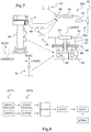
- the figure 2 illustrates a rotational maneuvering means 3.
- This operating means 3 comprises an element 300 wedged circumferentially between two mobile ends of two springs 501, 502 of the return system.
- a first spring 501 extends in a first direction DIR1 on an arc of a circle between a seat 250 secured to the support 2 to a first movable end 503.
- the second spring 502 extends in a second direction DIR2, opposed to first direction DIR1, on an arc of a circle between a seat 250 secured to the support 2 to a second mobile end 503.
- the return system 4 comprises a stop 505.
- the stop 505 comprises a first contact face adapted to block the extension in the first direction DIR1 of the first spring 501 by interference with the first movable end 503, and a second face contact block adapted to block the extension of the second spring 502 in the second direction DIR2 by interference with the second mobile end 504.
- the stop takes for example the shape of a shoulder of the support 2.
- This stop is further located at the right of the position that must reach the element 300 in the neutral position.
- the element 3 tends to compress the first spring 501.
- the first spring 501 stretches and repositions the operating member 3 in its neutral position, even in the event of a fault in the second spring 502 since the rotation of the operating member stops when the first movable end 503 reaches the stop 505.
- the element 3 tends to compress the second spring 502.
- the second spring 502 stretches and repositions the operating member 3 in its neutral position, even in the event of a fault in the first spring 501 since the rotation of the operating member 3 stops when the second mobile end 504 reaches the stop 505.
- the electric control device 1 may comprise a retaining system 6.
- This retaining system 6 has the function of tending to retain the operating means 3 in at least one so-called "indexed" position relative to the support 2.
- the operating means 3 can be positioned in a plurality of indexed switching positions distinct and different from the neutral position. The restraint system 6 then tends to maintain the operating means 3 in each switching position.
- an individual then moves the operating means 3 from the neutral position POS1 to a current position POS2 to give an order to a system, such as a propulsion system of an aircraft.
- the actuating means 3 then performs according to this example a rotation of an angle 100 around its operating axis AX.
- the angular position of the operating means 3 relative to the neutral position conditions the order given by the electrical control device 1 to a system.
- the return system 4 When the individual releases the operating means 3, the return system 4 returns the operating means 3 in the neutral position POS1. In the event of a malfunction of the return system, the restraint system tends to maintain the operating means in the position reached.
- the restraint system 6 may take the form of a friction system.
- a friction system may for example comprise an elastic member 7 tending to press a shoe 8 against an integral member in rotation with the operating means 3
- a notch system may be envisaged, such as a system comprising a ball and housings formed in a ring of the actuating means 3. An elastic member then tends to position a ball in a housing.
- the electrical control device 1 comprises two measuring means each measuring the position of the operating means.
- the electrical control device 1 comprises a first measurement system 10 which makes a first measurement representing the current position of the operating means 3.
- This first measurement system 10 is fixed to the support 2.
- the electrical control device 1 comprises a second measurement system 20 which makes a second measurement also representing this current position POS2.
- the first measurement system 10 and the second measurement system 20 are independent and dissimilar. Each measuring system therefore performs a measurement independently of the other measurement system.
- the first measurement system 10 is a means delivering the first measurement in the form of a first analogue type signal S1.
- Such a first measurement system 10 comprises according to the figure 1 a potentiometer 11 integrated in an electronic circuit 12.
- a displacement of the operating means 3 induces a variation of the resistance of the potentiometer 11. Therefore, the electronic circuit 12 delivers a first measurement M1 taking the form of a first electrical signal S1 having an electrical voltage depending on the position of the operating means 3.
- the first measurement M1 has the form of a first signal S1 having a voltage between 10.285 and 12 volts, 8.571 and 10. 285 volts, 6.857 and 8.571 volts, 5.142 and 6.857 volts, 3.428 and 5.142 volts, 1.714 and 3.428 volts, or between 0 and 1.714 volts depending on the position of the operating means 3 and therefore the position of the movable terminal of the potentiometer 11.
- the first measurement system may comprise a hall effect sensor or an active electrical RVDT rotation displacement sensor.
- the second measurement system 20 can deliver the second measurement M2 in the form of a second signal S2 that is not analog but digital.
- This second measurement system 20 is fixed to the support 2.
- the second measurement system 20 comprises an encoder wheel 21.
- the second measurement system 20 comprises a processing system 22 which cooperates with said encoder wheel 21 to determine a current bit value corresponding to said current position POS2.
- the encoder wheel 21 is integral in rotation with the operating means 3.
- the encoder wheel can take the form of a body of a knob of the operating means. This body may include angular perforations to generate a binary value.
- the processing system may comprise optical beam generators 23, 24, a sensor 25, 26 by an optical beam generator 23, 24, and a computing unit 27.
- figure 1 illustrates two optical beam generators. Nevertheless, the processing system includes an optical beam generator per bit of the signal to be produced.
- the processing system can assign the value 1 to the corresponding bit of the second measurement. Conversely, if no perforation is in front of a beam and does not reach a sensor, the processing system can assign the value 0 to the corresponding bit.
- the second measurement M2 has the form of a second signal S2 having a 3-bit binary value respectively equal to 001, 011, 010, 110, 111, 101, 100 as a function of the position of the operating means 3.
- the electrical control device 1 comprises a processing unit 30.
- This processing unit 30 may comprise an input 31 receiving the first signal S1 and the second signal S2 respectively carrying the first measurement M1 and the second measurement M2.
- processing unit 30 may comprise at least one output for transmitting a control signal ORD to a system.
- processing unit 30 may for example comprise a processor 32 executing instructions stored on a memory 33.
- processing unit may comprise an integrated circuit, a programmable system or a logic circuit, these examples not limiting the scope given to the term "processing unit".
- the processing unit 30 has the function of comparing the first measurement M1 and the second measurement M2 to generate an ORD command signal.
- the processing unit 30 estimates that the operating means 3 is in the neutral POS1 position when the first measurement and the second measurement do not correspond to the same position of the operating means, possibly to a threshold tolerance close. The processing unit then generates a predetermined ORD command signal corresponding in particular to this neutral position.
- the processing unit then generates a predetermined ORD command signal corresponding in particular to this particular position.
- the processing unit is located outside a first assembly provided with the support 2 as well as the operating means 3 and the first measuring system 10 and the second measuring system 20.
- the processing unit 30 is not fixed to the support 2.
- the processing unit is therefore deported compared to the first together.
- the first measurement system 10 and the second measurement system 20 are for example connected to at least one bus 36 opening in particular to the processing unit 30.
- a bus 36 may be a CAN bus.
- the processing unit 30 is a part of a computer 86 of an automatic control system controlling the pitch of the blades 83 of at least one propeller 800.
- the first measuring system 10 and the second measuring system 20 are for example connected to a plurality of processing units 30.
- This figure 4 indeed has an architecture provided with two control device 151, 152 for example for a driver and a co-pilot respectively.
- Each control device comprises a first measuring means 10, a second measuring means 20 and a processing unit 30.
- a processing unit may comprise a calculator.
- such a calculator may be a dual calculator that includes two channels.
- Each of the channels includes its own microprocessor.
- One of the two channels can be used to generate the COM control that can be inhibited due to the detection of inconsistency through the communication of the first channel and the second channel.
- each measurement means 10, 20 is connected to each processing unit by two links.
- the links shown are wired links, but may include buses and in particular CAN buses.
- the processing units can further be connected to each other.
- the processing unit 30 is a part of the first set being fixed to the support 2.
- the processing unit 30 takes the form of an FPGA logic circuit.
- the processing unit 30 is thus connected to the first measurement system 10 and to the second measurement system 20.
- the processing unit 30 can be connected to the system to be controlled for example by at least one bus 35, such as a CAN bus.
- the processing unit 30 is connected by at least one CAN bus to at least one computer 86 of an automatic control system controlling the pitch of the blades 83 of at least one propeller 800.
- the processing unit 30 can be connected by two CAN buses to two computers 86, each computer cooperating with a monitoring unit.
- the processing unit 30 can also be connected by two channels to a dual computer 86. Monitoring, even if possible between two computers of a duplex architecture, can be done between two dual channels of the same computer.
- the processing unit transmits a control signal via each bus 35 to each computer 86.
- the processing unit can also transmit the first measurement and the second measurement to this computer, or even the result of the comparison made.
- the computer can verify that the command signal ORD issued is correct by performing the same comparison as the processing unit.
- the electric control device 1 can be arranged on a rotary wing aircraft, namely a rotorcraft 50.
- the rotorcraft 50 has a fuselage 52.
- the fuselage 52 extends longitudinally from a tail 54 to a nose 53 along an AXROL roll axis.
- the fuselage extends transversely from a first side, said "left flank 56" for convenience, to a second side, said "right side 55" by convenience, along a pitch axis AXTANG.
- the fuselage extends in elevation from a lower surface 58 to an upper surface 57 along an AXLAC yaw axis.
- the AXROL roll axis and the AXLAC yaw axis together define a vertical anteroposterior plane of symmetry of the rotorcraft 1.
- a landing gear can project down from the lower surface 58 of the fuselage.
- the rotorcraft comprises a rotary wing 60 comprising at least one main rotor 61.
- This main rotor 61 overhangs the upper surface 57 of the fuselage 52.
- the main rotor 61 is provided with a plurality of blades 62 connected for example to a hub 63. blades 62 are called “main blades" for convenience.
- the main rotor rotates about an axis called "AXROT main axis of rotation" to participate at least partially in the lift or propulsion of the rotorcraft.
- This main axis of rotation can be stationary relative to the fuselage 52.
- the rotorcraft 1 may include a propulsion system 80 providing additional longitudinal thrust P to participate in the movement of this rotorcraft.
- the propulsion system 80 may tend to propel or tow the rotorcraft.
- This propulsion system 80 may comprise at least one propeller 800 comprising a plurality of blades 83 with variable pitch.
- the rotorcraft then has a lift surface 70 which extends substantially transversely on either side of the fuselage.
- This lifting surface 70 may for example comprise a left half-wing 71 extending from left flank 56 and right half-wing 72 extending from right flank 55.
- the lifting surface then carries a propeller 800 called “first propeller 81" and a propeller 800 called “second helix 82".
- first propeller 81 a propeller 800
- second helix 82 a propeller 800
- the left half-wing 71 carries the first propeller 81
- the right half-wing 72 carries the second propeller 82.
- the first propeller 81 and the second propeller 82 are arranged transversely on either side of the fuselage 52 .
- Each helix produces a thrust P1, P2 jointly generating the additional thrust P.
- the first thrust P1 generated by the first helix 81 may differ from the second thrust P2 generated by the second helix 82 for controlling the yaw movement of the rotorcraft.
- the rotorcraft 1 includes a power plant 75 for moving the first propeller 81, the second propeller 82 and the main rotor 60.
- Such a power plant 75 may comprise at least one motor 76 and a mechanical chain connecting the motor to the first propeller 81 as well as to the second propeller 82 and to the main rotor 60.
- the mechanical chain includes a power transmission box 77 provided with a rotor mast driving the main rotor in rotation.
- this transmission can be connected to a first power transmission chain 78 rotating the first propeller 81.
- this transmission can be connected to a second power transmission chain 79 driving in rotation the second helix 82.
- the rotorcraft 50 has multiple flight controls to control the movement of this rotorcraft.
- the pitch of the main rotor blades can be changed collectively and cyclically.
- the rotorcraft comprises a set of cyclic plates 65 provided with a non-rotating plate 66 and a turntable 67.
- the non-rotating plate 66 is connected to at least three actuators called "main actuators 69" of the servo-controlled type.
- the turntable 67 is connected to each blade 62 of the main rotor by respectively a pitch rod 68.
- the rotorcraft may comprise a collective lever 91.
- This collective lever 91 can rotate ROT 1 about an AXBASCU tilting axis to drive the main actuators in the same way.
- the rotorcraft may comprise a cyclic stick 92.
- This cyclic stick 92 can rotate ROT2 about a first axis and rotate ROT3 about a second axis to drive the main actuators differently to control the rotation. plate of the rotorcraft.
- the pitch of the blades 83 of each propeller 800 can be modified by a pitch modification system 850.
- a pitch modification system 850 of a propeller may comprise a hydraulic distributor 84 supplying a hydraulic jack.
- This jack can be arranged in a hub of the propeller by a long perforated shaft.
- This hydraulic distributor 84 can be controlled by a power transmission chain including an electric jack 85 by example.
- This electric jack can be controlled by a computer 86.
- a rudder 93 can communicate with the computer 86, to control the yaw movement of the aircraft through a thrust difference between the first thrust exerted by the first propeller and the second thrust exerted by the second propeller.
- an electric control device 1 can be implemented.
- the operating means 3 is arranged on the collective lever 91.
- the control signal emitted by the electrical control device 1 may be a control signal of a rate of change of the additional thrust.
- the electric control device 1 requires the variation of the additional thrust in a negative or positive rate of change.
- the computer 86 then orders the pitch modification systems 850 of the propellers to modify the pitch of the propeller blades according to this rate of variation.
- the computer applies at least one mathematical relationship or solicits a database to generate the pitch modification orders of the propeller blades corresponding to the rate of change of pitch required by the electrical control device 1.
- the positioning of the pitch of the propellers can be enslaved via, on the one hand, the generation of a command transmitted to the computer 86 and, on the other hand, of a position sensor measuring information relative to the pitch of a blade .
- a position sensor can be connected to the computer 86.
- the sensor of position can be and arranged closer to the blades, for example at a hydraulic distributor 84.
- the computer 86 then controls the electric cylinder 85 to comply with the command received with respect to a feedback given by the sensor of position.
- the aircraft 50 may comprise an emergency electrical operating member 40 connected to the propulsion system 80.
- this emergency electrical operating member 40 takes the form of a push button connected to the computer 86.
- the aircraft 50 may comprise a mechanical emergency maneuvering member 45 connected to the propulsion system.
- a mechanical emergency maneuvering member 45 may comprise a lever displacing the electric jack 85 for example.
- the figure 8 illustrates the process implemented by this aircraft.
- an individual can maneuver the operating means 3 to generate a change in the additional thrust.
- the first measurement system During a first measurement step STP11, the first measurement system generates the first measurement M1. During a second measurement step STP12, the second measurement system generates the second measurement M2.
- a comparison step STP2 the first measurement and the second measurement are compared to each other.
- a first rate of variation relating to a variation of the additional thrust corresponding to the first measurement, is determined using a first law giving said first rate of change according to the first measurement.
- a second rate of variation relating to a variation of the additional thrust corresponding to the second measurement, is determined by using a second law giving said second rate of variation as a function of the second measure.
- the comparison is made by comparing the first rate of change and the second rate of change during a comparison phase STP23. This comparison makes it possible to determine whether the first measurement and the second measurement simultaneously correspond to the same measured position of the operating means 3, or if the first measurement and the second measurement do not correspond to the same position.
- a variation rate of a thrust is generated to control the additional thrust P as a function of the position of the operating means 3 relative to a reference.
- the variation rate is generated as a function of a position called "measured position" of the operating means 3 when the first measurement and the second measurement simultaneously correspond to said measured position, said variation rate being set to zero when the first measurement and the second measure do not correspond to the same position.
- the rate of change generated to control the additional thrust P is equal to the value of these first and second rate of change.
- step STP5 thrust modification the rate of change developed in the third STP3 step is transmitted to the propulsion system to drive the thrust standard additional. If necessary, a step of changing the pitch of the blades of the propellers is implemented by applying said rate of change.
- This method may further comprise an STP4 step of positioning an average pitch of the propeller blades in a predetermined position when an emergency electrical operating member 40 is maneuvered by a pilot.
Abstract
La présente invention concerne un dispositif de commande électrique (1) muni d'un moyen de manoeuvre (3). Le dispositif de commande électrique (1) comprend un premier système de mesure (10) et un deuxième système de mesure (20) qui réalisent respectivement une première mesure et une deuxième mesure de la position courante du moyen de manoeuvre (3). Une unité de traitement compare la première mesure et la deuxième mesure pour générer un signal de commande (ORD) en fonction de ladite position courante, ladite unité de traitement (30) considérant que le moyen de manoeuvre (3) est dans une position neutre lorsque la première mesure et la deuxième mesure ne correspondent pas à une même position du moyen de manoeuvre.The present invention relates to an electric control device (1) provided with an operating means (3). The electrical control device (1) comprises a first measuring system (10) and a second measuring system (20) which respectively perform a first measurement and a second measurement of the current position of the operating means (3). A processing unit compares the first measurement and the second measurement to generate a control signal (ORD) according to said current position, said processing unit (30) considering that the operating means (3) is in a neutral position when the first measurement and the second measurement do not correspond to the same position of the operating means.
Description
La présente invention concerne un organe de commande électrique, un aéronef à voilure tournante comprenant un tel organe de commande, et un procédé appliqué par l'aéronef.The present invention relates to an electrical control member, a rotary wing aircraft comprising such a control member, and a method applied by the aircraft.
Un aéronef à voilure tournante de type hélicoptère comporte au moins un rotor principal qui participe au moins partiellement à la sustentation et à la propulsion de cet aéronef.A helicopter-type rotary wing aircraft comprises at least one main rotor which at least partially participates in the lift and propulsion of this aircraft.
En outre, un système permet au moins de contrôler le mouvement en lacet de l'aéronef.In addition, a system allows at least to control the yaw movement of the aircraft.
Dès lors, un tel hélicoptère comporte trois axes de pilotage. Un premier axe consiste à utiliser une première commande pour contrôler la norme du vecteur portance de l'aéronef. Un deuxième axe consiste à utiliser une deuxième commande pour commander l'orientation de ce vecteur portance, et un troisième axe consiste à utiliser une troisième commande pour commander le mouvement en lacet de l'aéronef.Therefore, such a helicopter has three axes of control. A first axis is to use a first command to control the vector of the lift vector of the aircraft. A second axis is to use a second command to control the orientation of this lift vector, and a third axis is to use a third command to control the yaw motion of the aircraft.
Par exemple, un hélicoptère peut comprendre un rotor principal participant à sa propulsion et sa sustentation. De plus, un hélicoptère peut comprendre un rotor auxiliaire participant au moins au contrôle du mouvement en lacet.For example, a helicopter may comprise a main rotor involved in its propulsion and lift. In addition, a helicopter may comprise an auxiliary rotor participating at least in the control of the yaw movement.
Dès lors, un levier de pas collectif permet de contrôler collectivement le pas des pales du rotor principal pour régler la portance de l'aéronef. Un manche cyclique permet de contrôler cycliquement le pas des pales du rotor principal pour régler l'orientation du vecteur portance de l'aéronef. Enfin, un palonnier permet de régler collectivement le pas des pales du rotor auxiliaire pour contrôler le mouvement en lacet de l'hélicoptère.Therefore, a collective lever collectively controls the pitch of the main rotor blades to adjust the lift of the aircraft. A cyclic stick cyclically controls the pitch of the main rotor blades to adjust the orientation of the lift vector of the aircraft. Finally, a rudder adjusts collectively the pitch of the auxiliary rotor blades to control the yaw movement of the helicopter.
Selon une autre réalisation, un hélicoptère peut comprendre deux rotors principaux, éventuellement coaxiaux.In another embodiment, a helicopter may comprise two main rotors, possibly coaxial.
Dès lors, un levier de pas collectif peut permettre de contrôler collectivement le pas des pales des rotors principaux pour régler la portance de l'aéronef. Un manche cyclique peut permettre de contrôler cycliquement le pas des pales des rotors principaux pour régler l'orientation du vecteur portance de l'aéronef. Enfin, un palonnier peut permettre de régler le couple exercé par au moins un rotor principal sur le fuselage de l'aéronef, afin de contrôler le mouvement en lacet de l'aéronef au travers de l'application de couples différents.Therefore, a collective lever can collectively control the pitch of the main rotor blades to adjust the lift of the aircraft. A cyclic stick can make it possible to control cyclically the pitch of the blades of the main rotors to adjust the orientation of the lift vector of the aircraft. Finally, a rudder can be used to adjust the torque exerted by at least one main rotor on the fuselage of the aircraft, to control the yaw movement of the aircraft through the application of different couples.
Un autre type d'aéronef à voilure tournante dit « hybride » par commodité comporte au moins un rotor qui participe au moins partiellement à la sustentation et à la propulsion de cet aéronef. De plus, l'aéronef comporte un dispositif permettant de contrôler le mouvement en lacet de l'aéronef. Cet aéronef comprend aussi un système apte à exercer, au moins selon le sens d'avancement de l'aéronef, une poussée dite « poussée additionnelle » par commodité. Cette poussée additionnelle est qualifiée d'« additionnelle » dans la mesure où cette poussée est axialement indépendante de la poussée exercée par la voilure tournante.Another type of rotary wing aircraft called "hybrid" for convenience includes at least one rotor that participates at least partially in the lift and propulsion of this aircraft. In addition, the aircraft comprises a device for controlling the yaw movement of the aircraft. This aircraft also includes a system capable of exercising, at least in the direction of advancement of the aircraft, a thrust called "additional thrust" for convenience. This additional thrust is described as "additional" insofar as this thrust is axially independent of the thrust exerted by the rotary wing.
Outre les trois axes de pilotage usuel, un tel aéronef à voilure tournante hydride comprend un quatrième axe de pilotage. Ce quatrième axe de pilotage consiste à utiliser une quatrième commande pour piloter la norme de la poussée additionnelle.In addition to the three usual steering axes, such a hybrid rotary wing aircraft comprises a fourth steering axis. This fourth control axis consists of using a fourth command to drive the additional thrust standard.
Par exemple, un aéronef à voilure tournante hybride peut comprendre un rotor principal qui participe au moins partiellement à la sustentation et à la propulsion de cet aéronef. De plus, cet aéronef à voilure tournante hybride comporte un système propulsif muni de deux hélices participant au moins partiellement à la propulsion de l'aéronef et au contrôle du mouvement en lacet de cet aéronef.For example, a hybrid rotary wing aircraft may comprise a main rotor which at least partially participates in the lift and propulsion of this aircraft. In addition, this hybrid rotary wing aircraft comprises a propulsion system provided with two propellers participating at least partially in the propulsion of the aircraft and in the control of the yaw movement of this aircraft.
Un levier de pas collectif peut permettre de contrôler collectivement le pas des pales du rotor principal pour régler la norme du vecteur portance de l'aéronef. Un manche cyclique peut permettre de contrôler cycliquement le pas des pales du rotor principal pour régler l'orientation du vecteur portance de l'aéronef.A collective pitch lever may collectively control the pitch of the main rotor blades to adjust the lift vector standard of the aircraft. A cyclic stick can be used to cyclically control the pitch of the main rotor blades to adjust the orientation of the lift vector of the aircraft.
En outre, une commande de poussée peut permettre à un pilote de régler collectivement un pas moyen des pales des hélices pour piloter la poussée additionnelle générée conjointement par les hélices.In addition, a thrust control may allow a pilot to collectively adjust an average pitch of the propeller blades to control the additional thrust generated jointly by the propellers.
De plus, un palonnier peut permettre de régler la répartition de cette poussée additionnelle entre les deux hélices pour contrôler le mouvement en lacet de l'aéronef au travers de l'application de poussées différentes à l'aide des hélices. Ce palonnier peut par exemple permettre de régler un pas différentiel, le pas des pales d'une hélice étant par exemple égal à la somme du pas moyen et de la moitié du pas différentiel, le pas des pales de l'autre hélice étant par exemple égal à la différence du pas moyen et de la moitié du pas différentiel.In addition, a rudder can be used to adjust the distribution of this additional thrust between the two propellers to control the yaw movement of the aircraft through the application of different thrusts using the propellers. This rudder can for example be used to adjust a differential pitch, the pitch of the blades of a helix being for example equal to the sum of the average pitch and the half of the differential pitch, the pitch of the blades of the other helix being for example equal to the difference of the average pitch and the half of the differential pitch.
La commande de poussée peut prendre la forme d'une commande « tout ou rien ». Lorsque la commande de poussée est manoeuvrée, cette commande de poussée génère un ordre d'augmentation ou de réduction du pas moyen des pales des hélices. Cet ordre est transmis à des actionneurs pour modifier le pas des pales des deux hélices de la même manière. Par exemple, un actionneur est agencé sur une chaîne de transmission mécanique contrôlant un distributeur hydraulique, ce distributeur hydraulique alimentant un vérin hydraulique apte à engendrer un mouvement des pales d'une hélice.Push control can take the form of an "all or nothing" command. When the thrust control is maneuvered, this thrust command generates an order of increase or decrease of the average pitch of the propeller blades. This order is transmitted to actuators to change the pitch of the blades of the two propellers in the same way. For example, an actuator is arranged on a mechanical transmission chain controlling a hydraulic distributor, the hydraulic distributor supplying a hydraulic cylinder capable of generating a movement of the blades of a propeller.
Une telle commande de poussée est intéressante. Néanmoins, la modification du pas moyen des hélices peut être trop lente pour pouvoir solliciter rapidement une augmentation de la puissance développée par l'installation motrice entrainant les hélices, ou encore trop rapide pour piloter finement la vitesse d'avancement de l'aéronef par exemple lors de vols à proximité d'autres aéronefs.Such thrust control is interesting. Nevertheless, the modification of the average pitch of the propellers can be too slow to quickly solicit an increase in power developed by the power plant driving the propellers, or too fast to finely control the speed of the aircraft for example when flying near other aircraft.
Par ailleurs, une commande de vol indépendante de la commande de poussée peut positionner les pales des hélices dans une position prédéterminée, notamment lors d'une phase de vol en autorotation.Furthermore, a flight control independent of the thrust control can position the blades of the propellers in a predetermined position, especially during an autorotation flight phase.
Une commande mécanique de secours peut aussi être prévue pour permettre de piloter les hélices en cas de dysfonctionnement de la commande de poussée. Cette commande mécanique peut comprendre un levier mécanique apte à déplacer mécaniquement ladite chaîne de transmission mécanique contrôlant un distributeur hydraulique.A mechanical emergency control can also be provided to enable the propellers to be controlled in the event of a malfunction of the thrust control. This mechanical control may comprise a mechanical lever capable of mechanically moving said mechanical transmission chain controlling a hydraulic distributor.
Par ailleurs, les aéronefs connus sous les marques Bell V-22® et Agusta Westland AW609® sont équipés de rotors basculants. Des commandes permettent de commander la poussée longitudinale de l'aéronef en pilotant le basculement des nacelles portant les rotors, assurant ainsi une transition entre un "mode de fonctionnement hélicoptère" et un "mode de fonctionnement avion". Cette situation s'écarte cependant des problèmes rencontrés pour piloter les hélices d'un aéronef hybride à voilure tournante.In addition, the aircraft known under the Bell V-22® and Agusta Westland AW609® brands are equipped with tilting rotors. Controls make it possible to control the longitudinal thrust of the aircraft by controlling the tilting of the pods carrying the rotors, thus ensuring a transition between a "helicopter operating mode" and a "plane operating mode". This situation, however, departs from the problems encountered in piloting the propellers of a hybrid aircraft with rotary wing.
Le brevet
Le document
Ce document
Le document
Le document
Le document
La présente invention a alors pour objet de proposer un dispositif de commande innovant pouvant notamment être utilisé pour piloter une poussée d'un aéronef.The present invention therefore aims to provide an innovative control device that can be used to control a thrust of an aircraft.
L'invention concerne donc un dispositif de commande électrique muni d'un moyen de manoeuvre et d'un support, le moyen de manoeuvre étant mobile par rapport à ce support, le moyen de manoeuvre étant destiné à être déplacé par rapport au support par un individu, le dispositif de commande électrique comprenant un premier système de mesure qui réalise une première mesure d'une position courante du moyen de manoeuvre par rapport à une position neutre.The invention therefore relates to an electrical control device provided with an operating means and a support, the operating means being movable relative to this support, the operating means being intended to be displaced with respect to the support by a individual, the electrical control device comprising a first measuring system which performs a first measurement of a current position of the operating means relative to a neutral position.
Le dispositif de commande électrique comprend un deuxième système de mesure qui réalise une deuxième mesure de la position courante, le premier système de mesure et le deuxième système de mesure étant indépendants et dissimilaires, le dispositif de commande comprenant une unité de traitement comparant la première mesure et la deuxième mesure pour générer un signal de commande en fonction de ladite position courante, l'unité de traitement considérant que le moyen de manoeuvre est dans la position neutre lorsque la première mesure et la deuxième mesure ne correspondent pas à une même position du moyen de manoeuvre.The electrical control device comprises a second measuring system which performs a second measurement of the current position, the first measuring system and the second measuring system being independent and dissimilar, the control device comprising a processing unit comparing the first measurement and the second measurement for generating a control signal according to said current position, the processing unit considering that the operating means is in the neutral position when the first measurement and the second measurement do not correspond to the same position of the means. maneuvering.
Dans ce cas de figure, une alerte sonore et/ou visuelle de détection de panne peut être émise par l'unité de traitement.In this case, an audible and / or visual fault detection alert can be emitted by the processing unit.
L'expression « moyen de manoeuvre » désigne un organe pouvant être manoeuvré par un individu. En particulier, cette expression désigne un organe mobile d'un commutateur électrique. Par exemple, le moyen de manoeuvre peut comprendre une molette mobile en rotation par rapport au support, un levier...The term "maneuvering means" means an organ that can be maneuvered by an individual. In particular, this expression designates a movable member of an electrical switch. For example, the operating means may comprise a wheel movable in rotation relative to the support, a lever ...
Les expressions « première mesure » et « deuxième mesure » représentent des données qui varient en fonction de la position du moyen de manoeuvre par rapport à une référence. Par exemple, la position angulaire d'une molette par rapport à une référence est mesurée au travers de la première mesure et de la deuxième mesure. Dès lors, pour deux positions différentes du moyen de manoeuvre, la première mesure et la deuxième mesure doivent prendre chacune deux valeurs différentes.The terms "first measure" and "second measure" represent data which vary according to the position of the means of maneuver relative to a reference. For example, the angular position of a wheel relative to a reference is measured through the first measurement and the second measurement. Therefore, for two different positions of the operating means, the first measurement and the second measurement must each take two different values.
L'expression « indépendantes et dissimilaires » signifie que le premier système de mesure et le deuxième système de mesure génèrent des signaux de natures différentes, bien que tous deux soient relatifs à la position du moyen de manoeuvre. La première mesure et la deuxième mesure représentent des données différentes, bien que représentatives toutes deux de la position du moyen de manoeuvre. Par exemple, la première mesure retranscrit la position du moyen de manoeuvre sous la forme d'un courant électrique présentant une certaine tension électrique, alors que la deuxième mesure retranscrit la position du moyen de manoeuvre sous la forme d'une valeur binaire.The expression "independent and dissimilar" means that the first measurement system and the second measurement system generate signals of different natures, although both are relative to the position of the operating means. The first measurement and the second measurement represent different data, although both are representative of the position of the operating means. For example, the first measurement retranscribes the position of the operating means in the form of an electric current having a certain electrical voltage, while the second measurement retranscribes the position of the operating means in the form of a binary value.
Ainsi, l'invention ne met pas en oeuvre un unique système de mesure mesurant la position du moyen de manoeuvre.Thus, the invention does not implement a single measuring system measuring the position of the operating means.
Au contraire, le dispositif de commande électrique comporte deux systèmes de mesure dissimilaires qui mesurent chacun la position du moyen de manoeuvre.On the contrary, the electrical control device comprises two dissimilar measuring systems which each measure the position of the operating means.
La première mesure et la deuxième mesure peuvent transiter par deux chemins différents jusqu'à l'unité de traitement. La première mesure et la deuxième mesure sont comparées pour vérifier que les systèmes de mesures fonctionnent correctement.The first measurement and the second measurement can go through two different paths up to the processing unit. The first measurement and the second measurement are compared to verify that the measurement systems are working properly.
Par exemple, chaque mesure peut être associée à un ordre à donner. Si la première mesure et la deuxième mesure sont relatives à deux ordres différents, l'unité de traitement en déduit la présence d'une incohérence.For example, each measure can be associated with an order to give. If the first measurement and the second measurement relate to two different orders, the processing unit deduces the presence of an inconsistency.
De manière alternative, chaque valeur de la première mesure peut être associée à une valeur théorique que devrait atteindre la deuxième mesure. L'unité de traitement détermine alors si la deuxième mesure correspond à la valeur théorique mémorisée. Dans la négative, l'unité de traitement en déduit la présence d'une incohérence.Alternatively, each value of the first measurement can be associated with a theoretical value that the second measurement should reach. The processing unit then determines whether the second measurement corresponds to the stored theoretical value. If not, the processing unit deduces the presence of an inconsistency.
En cas d'incohérence, l'unité de traitement en déduit qu'un système de mesure est en panne. Dès lors, l'unité de traitement génère le signal de commande prédéterminé et mémorisé correspondant à la position neutre du moyen de manoeuvre. L'unité de traitement ignore donc les informations données par le premier système de mesure et le deuxième système de mesure.In case of inconsistency, the processing unit deduces that a measuring system is down. Therefore, the processing unit generates the predetermined and stored control signal corresponding to the neutral position of the operating means. The processing unit therefore ignores the information given by the first measurement system and the second measurement system.
En cas d'incohérence, un état d'invalidité peut aussi être généré pour déterminer si un signal correspondant à la position neutre a été envoyé suite à une incohérence ou suite au positionnement du moyen de manoeuvre dans cette position neutre.In the event of inconsistency, a state of invalidity can also be generated to determine whether a signal corresponding to the neutral position has been sent following an inconsistency or following the positioning of the operating means in this neutral position.
De manière alternative, l'unité de traitement peut générer un signal de commande correspondant à la dernière mesure cohérente.Alternatively, the processing unit can generate a control signal corresponding to the last coherent measurement.
En cas d'incohérence, un état d'invalidité peut aussi être généré.In case of inconsistency, a state of invalidity can also be generated.
En l'absence d'incohérence, l'unité de traitement génère le signal de commande prédéterminé et mémorisé correspondant à la première mesure et à la deuxième mesure.In the absence of inconsistency, the processing unit generates the predetermined and stored control signal corresponding to the first measurement and the second measurement.
Cette caractéristique permet d'obtenir un dispositif visant à prévenir des modes communs de pannes, pour atteindre un niveau de fiabilité et de sécurité optimisé. Ainsi, le dispositif de commande électrique peut piloter une fonction importante d'un aéronef, telle qu'une poussée longitudinale sur un aéronef hybride à voilure tournante.This feature provides a device to prevent common modes of failure to achieve a level of reliability and enhanced security. Thus, the electrical control device can control an important function of an aircraft, such as a longitudinal thrust on a hybrid aircraft with rotary wing.
Par exemple, la première mesure et la deuxième mesure peuvent être prises en compte pour commander des actionneurs agissant sur la poussée longitudinale d'un aéronef selon une architecture de type commande (COM) et surveillance (MON) où les mesures élaborées par deux voies indépendantes doivent être en accord pour que l'action soit effectuée, ce ou ces actionneurs gelant leurs actions en cas de dissemblance entre les mesures reçues.For example, the first measurement and the second measurement can be taken into account for controlling actuators acting on the longitudinal thrust of an aircraft according to a command type architecture (COM) and monitoring (MON) where the measurements developed by two independent channels must be in agreement for the action to be performed, this or these actuators freezing their actions in case of dissimilarity between the measurements received.
La disponibilité de mesures indépendantes et dissimilaires permet de passiver, par traitement logiciel aval via deux voies de calcul indépendantes, le dysfonctionnement de l'une d'elles sans entrainer de commande intempestive.The availability of independent and dissimilar measurements allows to passivate, by downstream software processing via two independent calculation channels, the malfunction of one of them without causing untimely control.
Par ailleurs, le dispositif de commande électrique peut comporter une ou plusieurs des caractéristiques qui suivent.Furthermore, the electrical control device may comprise one or more of the following features.
Ainsi, le premier système de mesure peut être un moyen délivrant la première mesure sous la forme d'un premier signal de type analogique, le deuxième système de mesure étant un moyen délivrant la deuxième mesure sous la forme d'un deuxième signal de type numérique.Thus, the first measurement system may be a means delivering the first measurement in the form of a first analog type signal, the second measurement system being a means delivering the second measurement in the form of a second digital type signal. .
Le premier système de mesure peut ainsi émettre un signal analogique. Dès lors, la première mesure peut avoir la forme d'un courant électrique présentant une tension électrique qui varie en fonction de la position du moyen de manoeuvre, par exemple dans une plage allant de 0 à 12 volts.The first measurement system can thus emit an analog signal. Therefore, the first measurement may be in the form of an electric current having a voltage that varies depending on the position of the operating means, for example in a range from 0 to 12 volts.
A l'inverse, le deuxième système de mesure délivre un signal numérique. La deuxième mesure peut ainsi être une mesure numérique, par exemple de type « binaire réfléchie ». Le deuxième système de mesure peut en effet appliquer un code de Gray.Conversely, the second measurement system delivers a digital signal. The second measurement can thus be a digital measurement, for example of the "reflected binary" type. The second measurement system can indeed apply a Gray code.
Par exemple, le premier système de mesure peut comprendre un potentiomètre ou un capteur à effet Hall ou un capteur électrique actif de déplacements de rotation, la première mesure étant exprimée sous la forme d'un premier signal présentant une tension électrique dépendant de ladite position courante.For example, the first measurement system may comprise a potentiometer or a Hall effect sensor or an active electrical displacement displacement sensor, the first measurement being expressed as a first signal having an electrical voltage dependent on said current position.
Un capteur électrique actif de déplacements de rotation est connu sous l'acronyme « RVDT » qui correspond à l'expression Anglaise « Rotary Variable Differential Transformer ».An active electrical displacement sensor is known by the acronym "RVDT" which corresponds to the English expression "Rotary Variable Differential Transformer".
Par ailleurs, le deuxième système de mesure peut comprendre une roue codeuse solidaire en rotation du moyen de manoeuvre et un système de traitement coopérant avec la roue codeuse pour déterminer une valeur binaire courante correspondant à ladite position courante, la deuxième mesure étant exprimée sous la forme d'un deuxième signal comprenant ladite valeur binaire.Furthermore, the second measurement system may comprise a rotary wheel integral with the actuating means and a processing system cooperating with the coding wheel to determine a current binary value corresponding to said current position, the second measurement being expressed in the form a second signal comprising said binary value.
Le système de traitement peut être un système optique ou magnétique usuel.The treatment system may be a conventional optical or magnetic system.
Une roue codeuse est un générateur de code binaire pur. Une roue codeuse permet de renvoyer un signal numérique qui dépend du déplacement effectué par la roue codeuse.An encoder wheel is a pure binary code generator. An encoder wheel makes it possible to send back a digital signal which depends on the displacement effected by the encoder wheel.
Par exemple, la roue codeuse se présente sous la forme d'une roue perforée. Le système de traitement génère un faisceau lumineux qui éclaire une face de mesure de la roue. Suivant la position de la roue, le faisceau lumineux traverse la roue par une perforation et atteint alors un capteur, ou s'interrompt contre la face de mesure de la roue. Lorsqu'un capteur détecte la présence d'un faisceau, ce capteur émet un signal électrique.For example, the encoder wheel is in the form of a perforated wheel. The treatment system generates a light beam that illuminates a measuring face of the wheel. Depending on the position of the wheel, the light beam passes through the wheel through a perforation and then reaches a sensor, or stops against the measuring face of the wheel. When a sensor detects the presence of a beam, this sensor emits an electrical signal.
Par exemple et pour obtenir un signal numérique à trois bits, trois faisceaux et trois capteurs sont éventuellement utilisés. Un signal numérique comprenant un nombre de bits différents est envisageable, et par exemple un signal numérique à quatre bits.For example, to obtain a three-bit digital signal, three beams and three sensors are optionally used. A digital signal comprising a number of different bits is possible, and for example a four-bit digital signal.
Le degré de rotation d'une roue codeuse peut être encodé en code de Gray. Le code de Gray, également appelé « binaire réfléchi », permet de ne modifier qu'un seul bit quand un nombre est augmenté d'une unité pour éviter des états transitoires potentiellement gênants.The degree of rotation of an encoder wheel can be encoded in Gray code. Gray's code, also known as "reflected binary", allows only one bit to be changed when a number is increased by one to avoid potentially awkward transient states.
Selon un autre aspect, le dispositif de commande électrique peut comprendre un système de rappel tendant à rappeler le moyen de manoeuvre dans la position neutre.In another aspect, the electrical control device may comprise a return system tending to return the operating means in the neutral position.
Le système de rappel peut comprendre des ressorts ou des vérins à gaz miniatures associés à des butées mécaniques empêchant leur action au-delà du retour à la position neutre.The return system may comprise springs or miniature gas cylinders associated with mechanical stops preventing their action beyond the return to the neutral position.
Ce système de rappel tend à rappeler mécaniquement et à maintenir dans la position neutre le moyen de manoeuvre. Par suite, lorsqu'un individu déplace le moyen de rappel, cet individu exerce un effort à l'encontre de l'effort exercé par le système de rappel. Lorsque cet individu relâche le moyen de manoeuvre, le système de rappel déplace le moyen de manoeuvre vers sa position neutre.This return system tends to mechanically reminder and maintain in the neutral position the operating means. As a result, when an individual moves the biasing means, this individual exerts a force against the force exerted by the return system. When this individual releases the operating means, the return system moves the operating means to its neutral position.
Dès lors, un dysfonctionnement du système de rappel n'entraine pas une rotation intempestive du moyen de manoeuvre ce qui peut s'avérer précieux lorsque le dispositif de commande électrique commande un système sensible d'un aéronef.Therefore, a malfunction of the return system does not cause an inadvertent rotation of the operating means which can prove valuable when the electrical control device controls a sensitive system of an aircraft.
Par exemple, le système de rappel peut comporter un premier ressort et un deuxième ressort qui sont munis respectivement d'une première extrémité mobile et d'une deuxième extrémité mobile, ledit moyen de manoeuvre comprenant un élément agencé circonférentiellement entre la première extrémité mobile et la deuxième extrémité mobile, ledit système de rappel comprenant une butée, ledit premier ressort tendant à déplacer circonférentiellement selon un premier sens ladite première extrémité mobile contre la butée pour positionner l'organe de manoeuvre dans la position neutre, ledit deuxième ressort tendant à déplacer circonférentiellement selon un deuxième sens ladite deuxième extrémité mobile contre la butée pour positionner l'organe de manoeuvre dans la position neutre.For example, the return system may comprise a first spring and a second spring which are respectively provided with a first movable end and a second movable end, said actuating means comprising an element arranged circumferentially between the first movable end and the first movable end. second mobile end, said return system comprising a stop, said first spring tending to move circumferentially in a first direction said first end movable against the stop to position the operating member in the neutral position, said second spring tending to move circumferentially in a second direction said second end movable against the stop to position the operating member in the neutral position.
Selon un autre aspect, le dispositif de commande électrique peut comprendre un système de retenue tendant à retenir ledit moyen de manoeuvre dans au moins une position dite « indexée » par rapport au support.In another aspect, the electrical control device may comprise a retaining system tending to retain said operating means in at least one so-called "indexed" position relative to the support.
Le système de retenue peut prendre la forme d'un système par crantage, par exemple muni d'une bille et d'un organe élastique. Le système de retenue peut donc être du type décrit dans le document
De manière alternative ou complémentaire, le système de retenue peut être un système à friction. Un tel système à friction comporte un organe frottant contre le moyen de manoeuvre pour tendre à retenir le moyen de manoeuvre dans une position.Alternatively or additionally, the restraint system may be a friction system. Such a friction system comprises a member rubbing against the actuating means to tend to retain the operating means in a position.
Le système de retenue peut définir plusieurs positions de commutation dans lesquelles peut se trouver le moyen de manoeuvre par rapport au support, chaque position engendrant théoriquement des mesures différentes à la fois pour la première mesure et la deuxième mesure.The restraint system can define a plurality of switching positions in which the operating means can be located relative to the support, each position theoretically generating different measurements for both the first measurement and the second measurement.
Le système de retenue tend à retenir le moyen de manoeuvre dans chaque position. En cas de présence d'un système de rappel, le système de rappel fournit un effort de rappel sur le moyen de manoeuvre supérieur à l'effort de maintien exercé par le système de retenue. Ainsi, le système de retenue permet d'assurer le maintien en position du moyen de manoeuvre en cas de rupture du système de rappel. Le dysfonctionnement du système de rappel mécanique en position neutre n'entraîne donc pas la rotation intempestive du moyen de manoeuvre, même en présence de vibrations et en particulier dans un cockpit d'aéronef, du fait de l'action du système de retenue.The restraint system tends to retain the operating means in each position. In the presence of a return system, the return system provides a return force on the operating means greater than the holding force exerted by the restraint system. Thus, the restraint system makes it possible to maintain the position of the operating means in the event of failure of the reminder system. The malfunction of the mechanical return system in the neutral position therefore does not entail the inadvertent rotation of the operating means, even in the presence of vibrations and in particular in an aircraft cockpit, because of the action of the restraint system.
Selon un autre aspect, le dispositif de commande électrique peut présenter un premier ensemble muni du support ainsi que du moyen de manoeuvre et du premier système de mesure et du deuxième système de mesure, ladite unité de traitement étant fixée au premier ensemble en étant solidaire du support, ladite unité de traitement étant destinée à être reliée à au moins un calculateur indépendant physiquement du premier ensemble, ladite unité de traitement transmettant au calculateur ledit signal de commande, ledit signal de commande étant relatif à un paramètre dont la valeur est établie en fonction d'une position mesurée du moyen de manoeuvre lorsque la première mesure et la deuxième mesure correspondent chacune à ladite position mesurée ou de ladite position neutre lorsque la première mesure et la deuxième mesure ne correspondent pas à une même position du moyen de manoeuvre.According to another aspect, the electrical control device may have a first assembly provided with the support as well as the operating means and the first measurement system and the second measurement system, said processing unit being fixed to the first assembly while being integral with the support, said processing unit being intended to be connected to at least one physically independent computer of the first set, said processing unit transmitting to the computer said control signal, said control signal being relative to a parameter whose value is established according to a measured position of the operating means when the first measurement and the second measurement each correspond to said measured position or said neutral position when the first measurement and the second measurement do not correspond to the same position of the operating means.
Le signal de commande peut aussi comprendre une information de validité. Dès lors, le signal de commande permet d'indiquer si un ordre relatif à ladite position neutre est un ordre donné volontairement ou un ordre résultant une incohérence.The control signal may also include validity information. Therefore, the control signal makes it possible to indicate whether an order relative to said neutral position is a voluntary order or an order resulting in an inconsistency.
Selon cette première variante, le moyen de manoeuvre, le premier système de mesure, le deuxième système de mesure et l'unité de traitement comparant les mesures sont intégrés dans un même équipement apte à transmettre un ordre de commande à au moins un calculateur d'un système de pilotage automatique par au moins un bus, par exemple de type CAN. Le dispositif de commande électrique est alors aisément intégrable dans un aéronef par exemple.According to this first variant, the operating means, the first measuring system, the second measuring system and the processing unit comparing the measurements are integrated in the same equipment capable of transmitting a control command to at least one computer. an autopilot system by at least one bus, for example of the CAN type. The device electrical control is then easily integrable in an aircraft for example.
L'acronyme CAN correspond à l'expression anglaise « Controller Area Network » et désigne un type de bus particulier.The acronym CAN corresponds to the English expression "Controller Area Network" and refers to a particular type of bus.
L'unité de traitement peut par exemple prendre la forme d'un circuit logique programmable. Un circuit logique programmable est un circuit intégré logique qui peut être reprogrammé après sa fabrication. Un tel réseau comprend de nombreuses cellules logiques élémentaires et de bascules logiques librement connectables. Un circuit logique programmable peut prendre la forme d'un composant électronique connu sous l'acronyme « FPGA » correspondant à l'expression anglaise « field-programmable gate array ».The processing unit may for example take the form of a programmable logic circuit. A programmable logic circuit is a logic integrated circuit that can be reprogrammed after its manufacture. Such a network comprises numerous elementary logic cells and freely connectable logic flip-flops. A programmable logic circuit may take the form of an electronic component known by the acronym "FPGA" corresponding to the English expression "field-programmable gate array".
Par exemple, l'unité de traitement génère et transmet le signal de commande au calculateur d'un système de pilotage automatique pour contrôler un système propulsif d'un aéronef.For example, the processing unit generates and transmits the control signal to the computer of an autopilot system for controlling a propulsion system of an aircraft.
Selon une deuxième variante, le dispositif de commande électrique présente un premier ensemble muni du support ainsi que du moyen de manoeuvre et du premier système de mesure et du deuxième système de mesure, ladite unité de traitement n'étant pas fixée au premier ensemble, l'unité de traitement étant déportée par rapport à ce premier ensemble, ladite unité de traitement étant reliée au premier ensemble éventuellement par au moins un bus, ledit bus étant relié au premier système de mesure et au deuxième système de mesure, ladite unité de traitement transmettant au calculateur ledit signal de commande, ledit signal de commande étant relatif à un paramètre dont la valeur est établie en fonction d'une position mesurée du moyen de manoeuvre lorsque la première mesure et la deuxième mesure correspondent chacune à ladite position mesurée ou de ladite position neutre lorsque la première mesure et la deuxième mesure ne correspondent pas à une même position du moyen de manoeuvre.According to a second variant, the electrical control device has a first assembly provided with the support as well as the operating means and the first measurement system and the second measurement system, said processing unit not being fixed to the first set, the processing unit being offset with respect to this first set, said processing unit being connected to the first set possibly by at least one bus, said bus being connected to the first measuring system and to the second measuring system, said transmitting processing unit to the computer said control signal, said control signal being relative to a parameter whose value is established as a function of a measured position of the operating means when the first measurement and the second measurement each correspond to said measured position or said position neutral when the first measurement and the second measurement do not correspond to the same position of the operating means.
Selon cette deuxième variante, le moyen de manoeuvre, le premier système de mesure, le deuxième système de mesure sont intégrés dans un même équipement. Cet équipement est alors relié à une unité de traitement déportée, par exemple par un bus CAN ou des connections filaires.According to this second variant, the operating means, the first measuring system, the second measurement system are integrated in the same equipment. This equipment is then connected to a remote processing unit, for example by a CAN bus or wired connections.
Par exemple, l'unité de traitement est une partie intégrante d'un système de pilotage automatique qui contrôle un système propulsif d'un aéronef.For example, the processing unit is an integral part of an autopilot system that controls a propulsion system of an aircraft.
Outre un dispositif de commande électrique, l'invention vise un aéronef muni d'au moins un rotor principal participant au moins partiellement à la sustentation de l'aéronef, cet aéronef comprenant au moins un système propulsif distinct du rotor principal, le système propulsif générant une poussée dite « poussée additionnelle » pour au moins participer à la mise à l'avancement de l'aéronef.In addition to an electrical control device, the invention relates to an aircraft provided with at least one main rotor participating at least partially in the lift of the aircraft, this aircraft comprising at least one propulsion system separate from the main rotor, the propulsion system generating a thrust called "additional thrust" to at least participate in the progress of the aircraft.
Cet aéronef comporte un dispositif de commande électrique selon l'invention, le dispositif de commande électrique étant relié au système propulsif pour contrôler au moins partiellement ladite poussée additionnelle, le signal de commande requérant un taux de variation de ladite poussée additionnelle transmis au système propulsif.This aircraft comprises an electrical control device according to the invention, the electrical control device being connected to the propulsion system to at least partially control said additional thrust, the control signal requiring a rate of change of said additional thrust transmitted to the propulsion system.
Par exemple, le moyen de manoeuvre est monté sur un levier de pas collectif contrôlant collectivement le pas des pales du rotor principal.For example, the operating means is mounted on a collective lever collectively controlling the pitch of the main rotor blades.
En outre, le système propulsif peut comprendre au moins une hélice, et un système de modification du pas modifiant le pas des pales de cette hélice.In addition, the propulsion system may comprise at least one propeller, and a pitch modification system modifying the pitch of the blades of this propeller.
Dès lors et selon la variante, l'unité de traitement peut être reliée à un système de pilotage automatique du système propulsif, ou peut être une partie d'un tel système de pilotage automatique en étant reliée au système de modification du pas qui agit sur le pas des pales des hélices.Therefore and according to the variant, the processing unit can be connected to an automatic control system of the propulsion system, or can be a part of such an automatic control system by being connected to the pitch modification system which acts on the pitch of the blades of the propellers.
Indépendamment de la variante, la manoeuvre du moyen de manoeuvre n'induit pas la génération d'une commande tout ou rien se contentant de commander une augmentation ou une réduction de la poussée additionnelle. En effet, la manoeuvre du moyen de manoeuvre induit la génération d'un signal de commande pilotant un taux de variation de cette poussée additionnelle.Independently of the variant, the maneuvering of the operating means does not induce the generation of an on-off command merely controlling an increase or a reduction in the additional thrust. Indeed, the operation of the operating means induces the generation of a control signal controlling a rate of change of this additional thrust.
Le taux de variation peut être directement un taux de variation de la poussée additionnelle exprimée par exemple exprimé en watts par seconde, ou encore un taux de variation du pas des pales des hélices générant ladite poussée exprimée en degrés de pas par seconde.The rate of change can be directly a rate of variation of the additional thrust expressed for example expressed in watts per second, or a rate of variation of the pitch of the blades of the propellers generating said thrust expressed in degrees of steps per second.
Ce dispositif de commande électrique permet ainsi de piloter finement la vitesse de variation de la poussée additionnelle.This electrical control device thus makes it possible to finely control the speed of variation of the additional thrust.
L'aéronef peut de plus comporter une ou plusieurs des caractéristiques qui suivent.The aircraft may further include one or more of the following features.
Ainsi et selon une variante, le système propulsif comprenant au moins une hélice comprenant une pluralité de pales à pas variable, le système propulsif comprenant un système de modification de pas pour modifier ledit pas, l'unité de traitement est reliée au système de modification de pas.Thus, according to a variant, the propulsion system comprising at least one propeller comprising a plurality of blades with variable pitch, the propulsion system comprising a pitch modification system for modifying said pitch, the processing unit is connected to the modification system of the pitch. not.
Selon un autre aspect, l'aéronef peut comporter un organe de manoeuvre électrique de secours relié au système propulsif, pour requérir un taux de variation nul de la poussée additionnelle ou pour positionner le pas moyen des pales des hélices dans une position prédéterminée. Le positionnement des pales des hélices dans une position de refuge permet d'optimiser la charge de travail du pilote.According to another aspect, the aircraft may comprise an emergency electric actuator connected to the propulsion system, to require a zero variation rate of the additional thrust or to position the average pitch of the propeller blades in a predetermined position. The positioning of the propeller blades in a refuge position optimizes the pilot's workload.
Cet organe de manoeuvre électrique de secours peut prévaloir sur le dispositif de commande électrique et est indépendant du moyen de manoeuvre, ce moyen de manoeuvre étant inhibé lorsque l'organe de manoeuvre électrique de secours est manoeuvré.This emergency electric actuator can take precedence over the electrical control device and is independent of the operating means, this operating means being inhibited when the emergency operating maneuver is operated.
Pour éviter un appui intempestif sur l'organe de manoeuvre électrique de secours, un dispositif mécanique de protection du moyen de manoeuvre peut être appliqué. Une commande avionique peut aussi être utilisée pour désinhiber la fonction.To avoid inadvertent support on the emergency electrical operating device, a mechanical device for protecting the operating means can be applied. An avionics command can also be used to uninhibit the function.
Selon la variante, l'organe de manoeuvre électrique de secours peut être relié à un calculateur communiquant avec l'unité de traitement, ou encore à l'unité de traitement.According to the variant, the emergency electric actuator may be connected to a computer communicating with the processing unit, or to the processing unit.
L'organe de manoeuvre électrique de secours peut être sollicité lors de phases de vol en autorotation, ou en cas de grippage du moyen de manoeuvre.The emergency electric actuator can be solicited during autorotation flight phases, or in case of seizure of the operating means.
La mise en oeuvre de l'organe de manoeuvre électrique de secours permet de surpasser la commande reçue de ce moyen de manoeuvre et d'imposer un retour vers une position de commande de poussée refuge.The implementation of the emergency electric actuator makes it possible to surpass the command received from this operating means and to impose a return to a refuge thrust control position.
Selon un autre aspect, l'aéronef peut comporter un organe de manoeuvre mécanique de secours relié au système propulsif.In another aspect, the aircraft may include a mechanical emergency maneuvering member connected to the propulsion system.
Par exemple, cet organe de manoeuvre mécanique de secours prend la forme d'un levier agissant sur une chaîne de transmission de puissance reliée à une servocommande pilotant la poussée additionnelle, par exemple en pilotant le pas des pales d'une hélice.For example, this emergency mechanical maneuvering member takes the form of a lever acting on a power transmission chain connected to a servocontrol driving the thrust additional, for example by controlling the pitch of the blades of a propeller.
L'invention vise de plus, un procédé pour commander un système propulsif d'un aéronef.The invention further provides a method for controlling a propulsion system of an aircraft.
Ce procédé comporte les étapes suivantes :
- génération de la première mesure et de la deuxième mesure,
- comparaison de la première mesure et de la deuxième mesure,
- génération d'un taux de variation, de la poussée additionnelle ou du pas de pales d'hélices du système propulsif, pour piloter la poussée additionnelle en fonction de la position dudit moyen de manoeuvre par rapport à une référence, ledit taux de variation étant généré en fonction d'une position dite « position mesurée » du moyen de manoeuvre lorsque la première mesure et la deuxième mesure correspondent simultanément à ladite position mesurée du moyen de manoeuvre, ledit taux de variation étant réglé à zéro lorsque la première mesure et la deuxième mesure ne correspondent pas à une même position du moyen de manoeuvre.
- generation of the first measurement and the second measurement,
- comparison of the first measurement and the second measurement,
- generating a rate of change, of the additional thrust or the pitch of propeller blades of the propulsion system, for controlling the additional thrust as a function of the position of said actuating means with respect to a reference, said rate of variation being generated according to a position called "measured position" of the operating means when the first measurement and the second measurement simultaneously correspond to said measured position of the operating means, said rate of change being set to zero when the first measurement and the second measurement do not correspond to the same position of the operating means.
Dans le cas d'une incohérence entre la première mesure et la deuxième mesure, une alarme visuelle ou sonore peut être émise par un système d'alarme.In the case of an inconsistency between the first measurement and the second measurement, a visual or audible alarm can be issued by an alarm system.
Ce procédé peut de plus comporter une ou plusieurs des étapes suivantes.This method may further include one or more of the following steps.
Par exemple, l'étape de comparaison de la première mesure et de la deuxième mesure peut comporter les phases suivantes :
- détermination d'un premier taux de variation correspondant à la première mesure en utilisant une loi donnant ledit premier taux de variation en fonction de la première mesure,
- détermination d'un deuxième taux de variation correspondant à la deuxième mesure en utilisant une loi donnant ledit deuxième taux de variation en fonction de la deuxième mesure,
- comparaison du premier taux de variation et du deuxième taux de variation.
- determining a first rate of change corresponding to the first measurement by using a law giving said first rate of variation as a function of the first measurement,
- determining a second rate of variation corresponding to the second measurement by using a law giving said second rate of variation as a function of the second measurement,
- comparison of the first rate of change and the second rate of change.
De manière alternative, le procédé peut comparer la première mesure à une valeur théorique de la deuxième mesure.Alternatively, the method may compare the first measurement with a theoretical value of the second measurement.
Par exemple, lorsque la première mesure présentant une tension électrique comprise respectivement entre 10. 285 et 12 Volts, 8.571 et 10.285 Volts, 6.857 et 8.571 Volts, 5.142 et 6.857 Volts, 3.428 et 5.142 Volts, 1.714 et 3.428 Volts, et entre 0 et 1.714 Volt, la deuxième mesure devrait présenter une valeur binaire respectivement égale à 001, 011, 010, 110, 111, 101, 100.For example, when the first measurement has a voltage of between 10,285 and 12 volts, 8,571 and 10,285 volts, 6,857 and 8,571 volts, 5,142 and 6,857 volts, 3,428 and 5,142 volts, 1,714 and 3,428 volts, and between 0 and 1.714 Volt, the second measurement should have a binary value of 001, 011, 010, 110, 111, 101, 100, respectively.
Dans la négative, le taux de variation est considéré comme étant nul.If not, the rate of change is considered to be nil.
Dans l'affirmative, le taux de variation est égal au taux de variation correspondant à la valeur de la première mesure ou de la deuxième mesure. Par exemple, le taux de variation est égal au taux de variation correspondant à la valeur de la première mesure, la seconde mesure servant à surveiller le système.If so, the rate of change is equal to the rate of change corresponding to the value of the first or second measure. For example, the rate of change is equal to the rate of change corresponding to the value of the first measurement, the second measurement being used to monitor the system.
Indépendamment de la réalisation, l'unité de traitement peut donc appliquer au moins une loi mémorisée dans l'unité de traitement pour comparer la première mesure et la deuxième mesure. Une loi peut prendre la forme d'une ou plusieurs relations mathématiques ou encore d'un tableau de valeurs par exemple.Independently of the embodiment, the processing unit can therefore apply at least one law stored in the processing unit to compare the first measurement and the second measured. A law can take the form of one or more mathematical relationships or a table of values for example.
Selon un autre aspect, le procédé peut comporter une étape de positionnement d'un pas moyen des pales de chaque hélice dans une position prédéterminée lorsqu'un organe de manoeuvre électrique de secours est manoeuvré par un pilote.According to another aspect, the method may comprise a step of positioning an average pitch of the blades of each propeller in a predetermined position when an emergency electrical operating member is maneuvered by a pilot.
Selon un autre aspect, le système propulsif pouvant comprendre au moins une hélice comprenant une pluralité de pales à pas variable, ledit système propulsif pouvant comprendre un système de modification de pas pour modifier ledit pas variable, ledit taux de variation est un taux de variation dudit pas desdites pales de l'hélice, ledit procédé comportant une étape de modification dudit pas en appliquant ledit taux de variation dudit pas.According to another aspect, the propulsion system may comprise at least one propeller comprising a plurality of blades with variable pitch, said propulsion system may comprise a pitch modification system for modifying said variable pitch, said rate of variation is a variation rate of said pitch not said blades of the helix, said method comprising a step of modifying said pitch by applying said rate of variation of said pitch.
L'invention et ses avantages apparaîtront avec plus de détails dans le cadre de la description qui suit avec des exemples donnés à titre illustratif en référence aux figures annexées qui représentent :
- les
figures 1 à 5 , des schémas présentant un dispositif de commande électrique selon l'invention, - la
figure 6 , une vue d'un aéronef selon l'invention, - la
figure 7 , un schéma explicitant les commandes de vol de cet aéronef, et - la
figure 8 , un schéma explicitant le procédé selon l'invention.
- the
Figures 1 to 5 , diagrams showing an electric control device according to the invention, - the
figure 6 , a view of an aircraft according to the invention, - the
figure 7 , a diagram explaining the flight controls of this aircraft, and - the
figure 8 , a diagram explaining the method according to the invention.
Les éléments présents dans plusieurs figures distinctes sont affectés d'une seule et même référence.The elements present in several separate figures are assigned a single reference.
La
Ce dispositif de commande électrique 1 est muni d'un support 2 portant un moyen de manoeuvre 3. Le moyen de manoeuvre 3 est relié au support 2 par un système de fixation conférant une liberté de mouvement au moyen de manoeuvre 3 par rapport au support 2.This
Par exemple, le moyen de manoeuvre 3 comprend une molette mobile en rotation autour d'un axe de manoeuvre AX qui est immobile par rapport au support 2. Le système de fixation peut alors prendre la forme d'une tige 200 solidaire de la molette et portée par des paliers solidaires du support 2For example, the operating means 3 comprises a wheel movable in rotation about an axis of maneuver AX which is stationary relative to the
Une telle molette peut comprendre une circonférence pourvue de moyens de préhension pour favoriser son déplacement par une action manuelle d'un individu. La molette peut être du type du document
Par ailleurs, le dispositif de commande électrique 1 peut être muni d'un système de rappel 4. Un tel système de rappel 4 a pour fonction de tendre à rappeler le moyen de manoeuvre 3 dans une position de référence dite « position neutre POS1 ».Furthermore, the
Un tel système de rappel 4 peut par exemple comprendre au moins un ressort 5 ou au moins un vérin à gaz.Such a
La
Ainsi, un premier ressort 501 s'étend selon un premier sens DIR1 sur un arc de cercle entre un siège 250 solidaire du support 2 jusqu'à une première extrémité mobile 503. De même, le deuxième ressort 502 s'étend selon un deuxième sens DIR2, opposé au premier sens DIR1, sur un arc de cercle entre un siège 250 solidaire du support 2 jusqu'à une deuxième extrémité mobile 503.Thus, a
En outre, le système de rappel 4 comporte une butée 505. La butée 505 comporte une première face de contact apte à bloquer l'extension selon le premier sens DIR1 du premier ressort 501 par interférence avec la première extrémité mobile 503, et une deuxième face de contact apte à bloquer l'extension du deuxième ressort 502 selon le deuxième sens DIR2 par interférence avec la deuxième extrémité mobile 504. La butée prend par exemple la forme d'un épaulement du support 2.In addition, the
Cette butée est en outre localisée au droit de la position que doit atteindre l'élément 300 dans la position neutre.This stop is further located at the right of the position that must reach the
Par suite, suite à une rotation de l'organe de manoeuvre dans le deuxième sens DIR2, l'élément 3 tend à comprimer le premier ressort 501. Lorsqu'un pilote n'exerce plus d'effort sur l'organe de manoeuvre 3, le premier ressort 501 s'étire et repositionne l'organe de manoeuvre 3 dans sa position neutre, même en cas de défaut du deuxième ressort 502 puisque la rotation de l'organe de manoeuvre s'arrête lorsque la première extrémité mobile 503 atteint la butée 505.As a result, following a rotation of the operating member in the second direction DIR2, the
A l'inverse, suite à une rotation de l'organe de manoeuvre dans le premier sens DIR1, l'élément 3 tend à comprimer le deuxième ressort 502. Lorsqu'un pilote n'exerce plus d'effort sur l'organe de manoeuvre 3, le deuxième ressort 502 s'étire et repositionne l'organe de manoeuvre 3 dans sa position neutre, même en cas de défaut du premier ressort 501 puisque la rotation de l'organe de manoeuvre 3 s'arrête lorsque la deuxième extrémité mobile 504 atteint la butée 505.Conversely, following a rotation of the operating member in the first direction DIR1, the
Selon un autre aspect et en référence à la
En effet, le moyen de manoeuvre 3 peut être positionné dans une pluralité de positions de commutation indexées distinctes et différentes de la position neutre. Le système de retenue 6 tend alors à maintenir le moyen de manoeuvre 3 dans chaque position de commutation.Indeed, the operating means 3 can be positioned in a plurality of indexed switching positions distinct and different from the neutral position. The
En référence à la
Le moyen de manoeuvre 3 effectue alors selon cet exemple une rotation d'un angle 100 autour de son axe de manoeuvre AX.The actuating means 3 then performs according to this example a rotation of an
La position angulaire du moyen de manoeuvre 3 par rapport à la position neutre conditionne l'ordre donné par le dispositif de commande électrique 1 à un système.The angular position of the operating means 3 relative to the neutral position conditions the order given by the
Lorsque l'individu relâche le moyen de manoeuvre 3, le système de rappel 4 ramène le moyen de manoeuvre 3 dans la position neutre POS1. En cas de dysfonctionnement du système de rappel, le système de retenue tend à maintenir le moyen de manoeuvre dans la position atteinte.When the individual releases the operating means 3, the
Selon l'exemple de la
De manière alternative, un système à crans peut être envisagé, tel qu'un système comprenant une bille et des logements ménagés dans un anneau du moyen de manoeuvre 3. Un organe élastique tend alors à positionner une bille dans un logement.Alternatively, a notch system may be envisaged, such as a system comprising a ball and housings formed in a ring of the actuating means 3. An elastic member then tends to position a ball in a housing.
En référence à la
Ainsi, le dispositif de commande électrique 1 comprend un premier système de mesure 10 qui réalise une première mesure représentant la position courante du moyen de manoeuvre 3. Ce premier système de mesure 10 est fixé au support 2.Thus, the
De plus, le dispositif de commande électrique 1 comprend un deuxième système de mesure 20 qui réalise une deuxième mesure représentant aussi cette position courante POS2.In addition, the
Le premier système de mesure 10 et le deuxième système de mesure 20 sont indépendants et dissimilaires. Chaque système de mesure effectue donc une mesure indépendamment de l'autre système de mesure.The
Par exemple, le premier système de mesure 10 est un moyen délivrant la première mesure sous la forme d'un premier signal S1 de type analogique.For example, the
Un tel premier système de mesure 10 comprend selon la
Par exemple, la première mesure M1 a la forme d'un premier signal S1 présentant une tension électrique comprise entre 10.285 et 12 Volts, 8.571 et 10. 285 Volts, 6.857 et 8.571 Volts, 5.142 et 6.857 Volts, 3.428 et 5.142 Volts, 1.714 et 3.428 Volts, ou entre 0 et 1.714 Volt en fonction de la position du moyen de manoeuvre 3 et donc de la position de la borne mobile du potentiomètre 11.For example, the first measurement M1 has the form of a first signal S1 having a voltage between 10.285 and 12 volts, 8.571 and 10. 285 volts, 6.857 and 8.571 volts, 5.142 and 6.857 volts, 3.428 and 5.142 volts, 1.714 and 3.428 volts, or between 0 and 1.714 volts depending on the position of the operating means 3 and therefore the position of the movable terminal of the
De manière alternative au potentiomètre, le premier système de mesure peut comprendre un capteur à effet hall ou un capteur électrique actif de déplacements de rotation RVDT.As an alternative to the potentiometer, the first measurement system may comprise a hall effect sensor or an active electrical RVDT rotation displacement sensor.
Par ailleurs, le deuxième système de mesure 20 peut délivrer la deuxième mesure M2 sous la forme d'un deuxième signal S2 non pas analogique mais de type numérique. Ce deuxième système de mesure 20 est fixé au support 2.Moreover, the
Par exemple, le deuxième système de mesure 20 comprend une roue codeuse 21. De plus, le deuxième système de mesure 20 comprend un système de traitement 22 qui coopère avec ladite roue codeuse 21 pour déterminer une valeur binaire courante correspondant à ladite position courante POS2.For example, the
La roue codeuse 21 est solidaire en rotation du moyen de manoeuvre 3. Par exemple, la roue codeuse peut prendre la forme d'un corps d'une molette du moyen de manoeuvre. Ce corps peut comprendre des perforations angulaires pour générer une valeur binaire.The
Dès lors, le système de traitement peut comprendre des générateurs de faisceaux optiques 23, 24, un capteur 25, 26 par générateur de faisceau optique 23, 24, et une unité de calcul 27. La
Lorsque le faisceau traverse une perforation et atteint un capteur, le système de traitement peut attribuer la valeur 1 au bit correspondant de la deuxième mesure. A l'inverse, si aucune perforation n'est en face d'un faisceau et n'atteint pas un capteur, le système de traitement peut attribuer la valeur 0 au bit correspondant.When the beam passes through a perforation and reaches a sensor, the processing system can assign the
Par exemple, la deuxième mesure M2 a la forme d'un deuxième signal S2 ayant une valeur binaire à 3 bits respectivement égale à 001, 011, 010, 110, 111, 101, 100 en fonction de la position du moyen de manoeuvre 3.For example, the second measurement M2 has the form of a second signal S2 having a 3-bit binary value respectively equal to 001, 011, 010, 110, 111, 101, 100 as a function of the position of the operating means 3.
Pour analyser les mesures, le dispositif de commande électrique 1 comprend une unité de traitement 30.To analyze the measurements, the
Cette unité de traitement 30 peut comprendre une entrée 31 recevant le premier signal S1 et le deuxième signal S2 porteurs respectivement de la première mesure M1 et de la deuxième mesure M2.This
De plus, l'unité de traitement 30 peut comprendre au moins une sortie pour émettre vers un système un signal de commande ORD. En outre, l'unité de traitement 30 peut par exemple comprendre un processeur 32 exécutant des instructions mémorisées sur une mémoire 33.In addition, the
De manière alternative ou complémentaire, l'unité de traitement peut comprendre un circuit intégré, un système programmable, un circuit logique, ces exemples ne limitant pas la portée donnée à l'expression « unité de traitement ».Alternatively or additionally, the processing unit may comprise an integrated circuit, a programmable system or a logic circuit, these examples not limiting the scope given to the term "processing unit".
Indépendamment de sa réalisation, l'unité de traitement 30 a pour fonction de comparer la première mesure M1 et la deuxième mesure M2 pour générer un signal de commande ORD.Independently of its implementation, the
L'unité de traitement 30 estime que le moyen de manoeuvre 3 est dans la position neutre POS1 lorsque la première mesure et la deuxième mesure ne correspondent pas à une même position du moyen de manoeuvre, éventuellement à une tolérance de seuil près. L'unité de traitement génère alors un signal de commande ORD prédéterminé correspondant notamment à cette position neutre.The
A l'inverse, lorsque la première mesure et la deuxième mesure correspondent à une même position particulière du moyen de manoeuvre 3, l'unité de traitement génère alors un signal de commande ORD prédéterminée correspondant notamment à cette position particulière.Conversely, when the first measurement and the second measurement correspond to the same particular position of the operating means 3, the processing unit then generates a predetermined ORD command signal corresponding in particular to this particular position.
Selon la première variante de la
Contrairement au moyen de manoeuvre 3 ainsi qu'au premier système de mesure 10 et au deuxième système de mesure 20, l'unité de traitement 30 n'est pas fixée au support 2. L'unité de traitement est donc déportée par rapport au premier ensemble.Unlike the operating means 3 as well as the
Dès lors, le premier système de mesure 10 et le deuxième système de mesure 20 sont par exemple reliés à au moins un bus 36 débouchant notamment sur l'unité de traitement 30. Un tel bus 36 peut être un bus CAN.Therefore, the
Par exemple, l'unité de traitement 30 est une partie d'un calculateur 86 d'un système de pilotage automatique contrôlant le pas des pales 83 d'au moins une hélice 800.For example, the
Selon une alternative illustrée sur la
Cette
Chaque dispositif de commande comprend un premier moyen de mesure 10, un deuxième moyen de mesure 20 et une unité de traitement 30. Une telle unité de traitement peut comprendre un calculateur.Each control device comprises a first measuring means 10, a second measuring means 20 and a
Par exemple, un tel calculateur peut être un calculateur dual qui comprend deux voies. Chacune des voies comprend son propre microprocesseur. Une des deux voies peut servir à la génération de la commande COM pouvant être inhibée du fait de la détection d'incohérence grâce à la communication de la première voie et de la seconde voie.For example, such a calculator may be a dual calculator that includes two channels. Each of the channels includes its own microprocessor. One of the two channels can be used to generate the COM control that can be inhibited due to the detection of inconsistency through the communication of the first channel and the second channel.
Dès lors, chaque moyen de mesure 10, 20 est relié à chaque unité de traitement par deux liaisons. Les liaisons représentées sont des liaisons filaires, mais peuvent comprendre des bus et notamment des bus CAN.Therefore, each measurement means 10, 20 is connected to each processing unit by two links. The links shown are wired links, but may include buses and in particular CAN buses.
Les unités de traitement peuvent de plus être reliées l'une à l'autre.The processing units can further be connected to each other.
Selon la deuxième variante de la
L'unité de traitement 30 est ainsi reliée au premier système de mesure 10 et au deuxième système de mesure 20. De plus, l'unité de traitement 30 peut être reliée au système à commander par exemple par au moins un bus 35, tel qu'un bus CAN. Par exemple, l'unité de traitement 30 est reliée par au moins un bus CAN à au moins un calculateur 86 d'un système de pilotage automatique contrôlant le pas des pales 83 d'au moins une hélice 800.The
Par exemple, dans une architecture duplex, l'unité de traitement 30 peut être reliée par deux bus CAN à deux calculateurs 86, chaque calculateur coopérant avec une unité de surveillance.For example, in a duplex architecture, the
L'unité de traitement 30 peut aussi être reliée par deux voies un calculateur 86 dual. La surveillance, même si possible entre deux calculateurs d'une architecture duplex, peut se faire entre deux voies duales d'un même calculateur.The
Par ailleurs, l'unité de traitement émet un signal de commande via chaque bus 35 vers chaque calculateur 86. Toutefois, l'unité de traitement peut aussi transmettre la première mesure et la deuxième mesure à ce calculateur, voire le résultat de la comparaison effectuée. Ainsi, le calculateur peut vérifier que le signal de commande ORD émis est correct en effectuant la même comparaison que l'unité de traitement.Furthermore, the processing unit transmits a control signal via each
En référence à la
Le giravion 50 comporte un fuselage 52. Le fuselage 52 s'étend longitudinalement d'une queue 54 vers un nez 53 le long d'un axe de roulis AXROL. De plus, le fuselage s'étend transversalement d'un premier flanc, dit « flanc gauche 56 » par commodité, vers un deuxième flanc, dit « flanc droit 55 » par commodité, le long d'un axe de tangage AXTANG. Enfin, le fuselage s'étend en élévation d'une surface inférieure 58 vers une surface supérieure 57 le long d'un axe de lacet AXLAC.The
L'axe de roulis AXROL et l'axe de lacet AXLAC définissent conjointement un plan antéropostérieur vertical de symétrie du giravion 1.The AXROL roll axis and the AXLAC yaw axis together define a vertical anteroposterior plane of symmetry of the
Classiquement, un train d'atterrissage peut saillir vers le bas de la surface inférieure 58 du fuselage.Conventionally, a landing gear can project down from the
Le giravion comporte une voilure tournante 60 comprenant au moins un rotor principal 61. Ce rotor principal 61 surplombe la surface supérieure 57 du fuselage 52. Le rotor principal 61 est pourvu d'une pluralité de pales 62 reliées par exemple à un moyeu 63. Ces pales 62 sont dites « pales principales » par commodité.The rotorcraft comprises a
Le rotor principal effectue une rotation autour d'un axe dénommé « axe de rotation principal AXROT » pour participer au moins partiellement à la sustentation voire à la propulsion du giravion. Cet axe de rotation principal peut être immobile par rapport au fuselage 52.The main rotor rotates about an axis called "AXROT main axis of rotation" to participate at least partially in the lift or propulsion of the rotorcraft. This main axis of rotation can be stationary relative to the
Par ailleurs, le giravion 1 peut comporter un système propulsif 80 procurant une poussée additionnelle longitudinale P pour participer au déplacement de ce giravion. Le système propulsif 80 peut tendre à propulser ou à tracter le giravion.Furthermore, the
Ce système propulsif 80 peut comprendre au moins une hélice 800 comprenant une pluralité de pales 83 à pas variable.This
Par exemple, le giravion possède alors une surface sustentatrice 70 qui s'étend sensiblement transversalement de part et d'autre du fuselage. Cette surface sustentatrice 70 peut par exemple comprendre une demi-aile gauche 71 s'étendant à partir du flanc gauche 56 et une demi-aile droite 72 s'étendant à partir du flanc droit 55.For example, the rotorcraft then has a
La surface sustentatrice porte alors une hélice 800 dite « première hélice 81 » et une hélice 800 dite « deuxième hélice 82 ». Par exemple, la demi-aile gauche 71 porte la première hélice 81 , et la demi-aile droite 72 porte la deuxième hélice 82. La première hélice 81 et la deuxième hélice 82 sont donc agencées transversalement de part et d'autre du fuselage 52.The lifting surface then carries a
Chaque hélice produit une poussée P1, P2 générant conjointement la poussée additionnelle P. La première poussée P1 générée par la première hélice 81 peut différer de la deuxième poussée P2 générée par la deuxième hélice 82 pour le contrôle du mouvement en lacet du giravion.Each helix produces a thrust P1, P2 jointly generating the additional thrust P. The first thrust P1 generated by the first helix 81 may differ from the second thrust P2 generated by the second helix 82 for controlling the yaw movement of the rotorcraft.
Par ailleurs, le giravion 1 comporte une installation motrice 75 pour mettre en mouvement la première hélice 81, la deuxième hélice 82 et le rotor principal 60.In addition, the
Une telle installation motrice 75 peut comporter au moins un moteur 76 et une chaîne mécanique reliant le moteur à la première hélice 81 ainsi qu'à la deuxième hélice 82 et au rotor principal 60.Such a
Par exemple, la chaîne mécanique inclut une boîte de transmission de puissance 77 munie d'un mât rotor entraînant en rotation le rotor principal. De plus, cette boîte de transmission peut être reliée à une première chaîne de transmission 78 de puissance entraînant en rotation la première hélice 81. De même, cette boîte de transmission peut être reliée à une deuxième chaîne de transmission 79 de puissance entraînant en rotation la deuxième hélice 82.For example, the mechanical chain includes a
D'autres architectures sont envisageables.Other architectures are possible.
En référence à la
En effet, le pas des pales du rotor principal peut être modifié collectivement et cycliquement.Indeed, the pitch of the main rotor blades can be changed collectively and cyclically.
Par exemple, le giravion comprend un ensemble de plateaux cycliques 65 muni d'un plateau non tournant 66 et d'un plateau tournant 67. Le plateau non tournant 66 est relié à au moins trois actionneurs dit « actionneurs principaux 69 » de type servocommande par exemple. Le plateau tournant 67 est relié à chaque pale 62 du rotor principal par respectivement une bielle de pas 68.For example, the rotorcraft comprises a set of
Dès lors, le giravion peut comprendre un levier de pas collectif 91. Ce levier de pas collectif 91 peut effectuer une rotation ROT 1 autour d'un axe de basculement AXBASCU pour piloter les actionneurs principaux de la même manière.Therefore, the rotorcraft may comprise a
De plus, le giravion peut comprendre un manche cyclique 92. Ce manche cyclique 92 peut effectuer une rotation ROT2 autour d'un premier axe et une rotation ROT3 autour d'un deuxième axe pour piloter les actionneurs principaux de manière différente afin de contrôler l'assiette du giravion.In addition, the rotorcraft may comprise a
En outre, le pas des pales 83 de chaque hélice 800 peut être modifié par un système de modification de pas 850.In addition, the pitch of the
A titre illustratif, un système de modification de pas 850 d'une hélice peut comprendre un distributeur hydraulique 84 alimentant hydrauliquement un vérin. Ce vérin peut être agencé dans un moyeu de l'hélice par un arbre long perforé. Ce distributeur hydraulique 84 peut être piloté par une chaîne de transmission de puissance incluant un vérin électrique 85 par exemple. Ce vérin électrique peut être commandé par un calculateur 86.As an illustration, a
Un palonnier 93 peut communiquer avec le calculateur 86, pour piloter le mouvement en lacet de l'aéronef au travers d'une différence de poussée entre la première poussée exercée par la première hélice et la deuxième poussée exercée par la deuxième hélice.A
Pour piloter la norme de la poussée additionnelle, un dispositif de commande électrique 1 selon l'invention peut être implémenté. Par exemple, le moyen de manoeuvre 3 est agencé sur le levier de pas collectif 91.To drive the standard of the additional thrust, an
Dès lors, le signal de commande émis par le dispositif de commande électrique 1 peut être un signal de commande d'un taux de variation de la poussée additionnelle. Lorsqu'un pilote manoeuvre le moyen de manoeuvre 3, le dispositif de commande électrique 1 requiert la variation de la poussée additionnelle selon un taux de variation négatif ou positif. Le calculateur 86 ordonne alors aux systèmes de modification de pas 850 des hélices de modifier le pas des pales des hélices selon ce taux de variation.Therefore, the control signal emitted by the
Par exemple, le calculateur applique au moins une relation mathématique ou sollicite une base de données pour générer les ordres de modification du pas des pales des hélices correspondant au taux de variation de pas requis par le dispositif de commande électrique 1.For example, the computer applies at least one mathematical relationship or solicits a database to generate the pitch modification orders of the propeller blades corresponding to the rate of change of pitch required by the
En effet, le positionnement du pas des hélices peut être asservi via, d'une part la génération d'une commande transmise au calculateur 86 et, d'autre part d'un capteur de position mesurant une information relative au pas d'une pale. Un tel capteur de position peut être relié au calculateur 86. De plus le capteur de position peut être et agencé au plus près des pales, par exemple au niveau d'un distributeur hydraulique 84. Le calculateur 86 contrôle alors le vérin électrique 85 pour respecter la commande reçue au regard d'un retour d'information donné par le capteur de position.Indeed, the positioning of the pitch of the propellers can be enslaved via, on the one hand, the generation of a command transmitted to the
Par ailleurs, l'aéronef 50 peut comporter un organe de manoeuvre électrique de secours 40 relié au système propulsif 80. Par exemple, cet organe de manoeuvre électrique de secours 40 prend la forme d'un bouton poussoir relié au calculateur 86.Moreover, the
Selon un autre aspect, l'aéronef 50 peut comporter un organe de manoeuvre mécanique de secours 45 relié au système propulsif. Un tel organe de manoeuvre mécanique de secours 45 peut comprendre un levier déplaçant le vérin électrique 85 par exemple.In another aspect, the
La
Durant une première étape STP1, un individu peut manoeuvrer le moyen de manoeuvre 3 pour générer une modification de la poussée additionnelle.During a first step STP1, an individual can maneuver the operating means 3 to generate a change in the additional thrust.
Durant une première étape de mesure STP11 le premier système de mesure génère la première mesure M1. Durant une deuxième étape de mesure STP12, le deuxième système de mesure génère la deuxième mesure M2.During a first measurement step STP11, the first measurement system generates the first measurement M1. During a second measurement step STP12, the second measurement system generates the second measurement M2.
Durant une étape de comparaison STP2, la première mesure et la deuxième mesure sont comparées l'une à l'autre.During a comparison step STP2, the first measurement and the second measurement are compared to each other.
Selon une réalisation, durant une première phase STP21 de l'étape de comparaison STP2, un premier taux de variation, relatif à une variation de la poussée additionnelle correspondant à la première mesure, est déterminé en utilisant une première loi donnant ledit premier taux de variation en fonction de la première mesure.According to one embodiment, during a first phase STP21 of the comparison step STP2, a first rate of variation, relating to a variation of the additional thrust corresponding to the first measurement, is determined using a first law giving said first rate of change according to the first measurement.
Durant une deuxième phase STP22 de l'étape de comparaison STP2, un deuxième taux de variation, relatif à une variation de la poussée additionnelle correspondant à la deuxième mesure, est déterminé en utilisant une deuxième loi donnant ledit deuxième taux de variation en fonction de la deuxième mesure.During a second phase STP22 of the comparison step STP2, a second rate of variation, relating to a variation of the additional thrust corresponding to the second measurement, is determined by using a second law giving said second rate of variation as a function of the second measure.
Dès lors, la comparaison s'opère en comparant le premier taux de variation et le deuxième taux de variation durant une phase de comparaison STP23. Cette comparaison permet de déterminer si la première mesure et la deuxième mesure correspondent simultanément à une même position mesurée du moyen de manoeuvre 3, ou si la première mesure et la deuxième mesure ne correspondent pas à une même position.Therefore, the comparison is made by comparing the first rate of change and the second rate of change during a comparison phase STP23. This comparison makes it possible to determine whether the first measurement and the second measurement simultaneously correspond to the same measured position of the operating means 3, or if the first measurement and the second measurement do not correspond to the same position.
Durant une troisième étape STP3, un taux de variation d'une poussée est généré pour piloter la poussée additionnelle P en fonction de la position du moyen de manoeuvre 3 par rapport à une référence.During a third step STP3, a variation rate of a thrust is generated to control the additional thrust P as a function of the position of the operating means 3 relative to a reference.
Le taux de variation est généré en fonction d'une position dite « position mesurée » du moyen de manoeuvre 3 lorsque la première mesure et la deuxième mesure correspondent simultanément à ladite position mesurée, ledit taux de variation étant réglé à zéro lorsque la première mesure et la deuxième mesure ne correspondent pas à une même position.The variation rate is generated as a function of a position called "measured position" of the operating means 3 when the first measurement and the second measurement simultaneously correspond to said measured position, said variation rate being set to zero when the first measurement and the second measure do not correspond to the same position.
Le cas échéant, si le premier taux de variation est égal au deuxième taux de variation, le taux de variation généré pour piloter la poussée additionnelle P est égal à la valeur de ces premier et deuxième taux de variation.If necessary, if the first rate of change is equal to the second rate of change, the rate of change generated to control the additional thrust P is equal to the value of these first and second rate of change.
Par contre, lorsque le premier taux de variation n'est pas égal au deuxième taux de variation, le taux de variation généré pour piloter la poussée additionnelle P est égal à zéro.By cons, when the first rate of change is not equal to the second rate of change, the rate of change generated to drive the additional thrust P is zero.
Durant une étape de modification de la poussée STP5, le taux de variation élaboré lors de la troisième étape STP3 est transmis au système propulsif pour piloter la norme de la poussée additionnelle. Le cas échéant, une étape de modification du pas des pales des hélices est mise en oeuvre en appliquant ledit taux de variation.During a step STP5 thrust modification, the rate of change developed in the third STP3 step is transmitted to the propulsion system to drive the thrust standard additional. If necessary, a step of changing the pitch of the blades of the propellers is implemented by applying said rate of change.
Ce procédé peut de plus comporter une étape STP4 de positionnement d'un pas moyen des pales des hélices dans une position prédéterminée lorsqu'un organe de manoeuvre électrique de secours 40 est manoeuvré par un pilote.This method may further comprise an STP4 step of positioning an average pitch of the propeller blades in a predetermined position when an emergency
Naturellement, la présente invention est sujette à de nombreuses variations quant à sa mise en oeuvre. Bien que plusieurs modes de réalisation aient été décrits, on comprend bien qu'il n'est pas concevable d'identifier de manière exhaustive tous les modes possibles. Il est bien sûr envisageable de remplacer un moyen décrit par un moyen équivalent sans sortir du cadre de la présente invention.Naturally, the present invention is subject to many variations as to its implementation. Although several embodiments have been described, it is well understood that it is not conceivable to exhaustively identify all the possible modes. It is of course conceivable to replace a means described by equivalent means without departing from the scope of the present invention.
Claims (17)
caractérisé en ce que ledit dispositif de commande électrique (1) comprend un deuxième système de mesure (20) qui réalise une deuxième mesure de ladite position courante (POS2), le premier système de mesure (10) et le deuxième système de mesure (20) étant indépendants et dissimilaires, le dispositif de commande électrique (1) comprenant une unité de traitement (30) comparant la première mesure et la deuxième mesure pour générer un signal de commande (ORD) en fonction de ladite position courante (POS2), ladite unité de traitement (30) considérant que le moyen de manoeuvre (3) est dans ladite position neutre (POS1) lorsque la première mesure et la deuxième mesure ne correspondent pas à une même position du moyen de manoeuvre.Electric control device (1) provided with an operating means (3) and a support (2), the operating means (3) being movable relative to this support (2), said operating means (3) ) being adapted to be displaced relative to the support (2) by an individual, said electrical control device (1) comprising a first measuring system (10) which makes a first measurement of a current position (POS2) of the means of operation (3) with respect to a neutral position,
characterized in that said electrical control device (1) comprises a second measurement system (20) which performs a second measurement of said current position (POS2), the first measurement system (10) and the second measurement system (20). ) being independent and dissimilar, the electric control device (1) comprising a processing unit (30) comparing the first measurement and the second measurement to generate a control signal (ORD) according to said current position (POS2), said processing unit (30) considering that the operating means (3) is in said neutral position (POS1) when the first measurement and the second measurement do not correspond to the same position of the operating means.
caractérisé en ce que le premier système de mesure (10) est un moyen délivrant la première mesure sous la forme d'un premier signal (S1) de type analogique, le deuxième système de mesure (20) étant un moyen délivrant la deuxième mesure sous la forme d'un deuxième signal (S2) de type numérique.Electrical control device according to claim 1,
characterized in that the first measuring system (10) is a means for delivering the first measurement in the form of a first analogue-type signal (S1), the second measurement system (20) being a means for delivering the second measurement under the form of a second signal (S2) of digital type.
caractérisé en ce que le premier système de mesure (10) comprend un potentiomètre ou un capteur à effet Hall ou un capteur électrique actif de déplacements de rotation, la première mesure étant exprimée sous la forme d'un premier signal présentant une tension électrique dépendant de ladite position courante.Electrical control device according to one of Claims 1 to 2,
characterized in that the first measuring system (10) comprises a potentiometer or a Hall effect sensor or an active electrical displacement displacement sensor, the first measurement being expressed as a first signal having a voltage dependent on said current position.
caractérisé en ce que le deuxième système de mesure (20) comprend une roue codeuse (21) solidaire en rotation du moyen de manoeuvre (3) et un système de traitement (22) coopérant avec ladite roue codeuse (21) pour déterminer une valeur binaire courante correspondant à ladite position courante (POS2), la deuxième mesure étant exprimée sous la forme d'un deuxième signal (S2) comprenant ladite valeur binaire.Electrical control device according to one of Claims 1 to 3,
characterized in that the second measuring system (20) comprises an encoder wheel (21) integral in rotation with the operating means (3) and a processing system (22) cooperating with said encoder wheel (21) for determining a binary value current corresponding to said current position (POS2), the second measurement being expressed in the form of a second signal (S2) comprising said binary value.
caractérisé en ce que ledit dispositif de commande électrique (1) comprend un système de rappel (4) tendant à rappeler ledit moyen de manoeuvre (3) dans ladite position neutre (POS1).Electrical control device according to one of Claims 1 to 4,
characterized in that said electrical control device (1) comprises a return system (4) tending to return said operating means (3) in said neutral position (POS1).
caractérisé en ce que ledit système de rappel (4) comporte un premier ressort (501) et un deuxième ressort (502) qui sont munis respectivement d'une première extrémité mobile (503) et d'une deuxième extrémité mobile (504), ledit moyen de manoeuvre (3) comprenant un élément agencé circonférentiellement entre la première extrémité mobile (503) et la deuxième extrémité mobile (504), ledit système de rappel (4) comprenant une butée (505), ledit premier ressort (501) tendant à déplacer circonférentiellement selon un premier sens (DIR1) ladite première extrémité mobile (503) contre la butée (505) pour positionner l'organe de manoeuvre (3) dans la position neutre, ledit deuxième ressort (502) tendant à déplacer circonférentiellement selon un deuxième sens (DIR2) ladite deuxième extrémité mobile (504) contre la butée (505) pour positionner l'organe de manoeuvre dans la position neutre.Electrical control device according to claim 5,
characterized in that said return system (4) comprises a first spring (501) and a second spring (502) which are respectively provided with a first movable end (503) and a second movable end (504), said operating means (3) comprising an element arranged circumferentially between the first movable end (503) and the second movable end (504), said return system (4) comprising a stop (505), said first spring (501) tending to move circumferentially in a first direction (DIR1) said first movable end (503) against the stop (505) for positioning the operating member (3) in the neutral position, said second spring (502) tending to move circumferentially in a second direction (DIR2) said second movable end (504) against the stop (505) for positioning the operating member in the neutral position.
caractérisé en ce que ledit dispositif de commande électrique (1) comprend un système de retenue (6) tendant à retenir ledit moyen de manoeuvre (3) dans au moins une position dite « indexée » par rapport au support (2).Electrical control device according to one of Claims 1 to 4,
characterized in that said electrical control device (1) comprises a retaining system (6) tending to retain said actuating means (3) in at least one so-called "indexed" position relative to the support (2).
caractérisé en ce que ledit dispositif de commande électrique (1) présente un premier ensemble muni du support (2) ainsi que du moyen de manoeuvre (3) et du premier système de mesure (10) et du deuxième système de mesure (20), ladite unité de traitement (30) étant fixée au premier ensemble en étant solidaire du support (2), ladite unité de traitement (30) étant destinée à être reliée à au moins un calculateur (86) indépendant physiquement du premier ensemble, ladite unité de traitement (30) transmettant au calculateur (86) ledit signal de commande (ORD), ledit signal de commande (ORD) étant relatif à un paramètre dont la valeur est établie en fonction d'une position mesurée lorsque la première mesure et la deuxième mesure correspondent chacune à ladite position mesurée ou de ladite position neutre (POS1) lorsque la première mesure et la deuxième mesure ne correspondent pas à une même position.Electrical control device according to one of Claims 1 to 7,
characterized in that said electrical control device (1) has a first assembly provided with the support (2) as well as the operating means (3) and the first measuring system (10) and the second measuring system (20), said processing unit (30) being fixed to the first assembly while being secured to the support (2), said processing unit (30) being intended to be connected to at least one computer (86) physically independent of the first assembly, said unit of processing (30) transmitting to the computer (86) said control signal (ORD), said control signal (ORD) relating to a parameter whose value is set according to a measured position when the first measurement and the second measurement each correspond to said measured position or said neutral position (POS1) when the first measure and the second measure do not correspond to the same position.
caractérisé en ce que ledit dispositif de commande électrique (1) présente un premier ensemble muni du support (2) ainsi que du moyen de manoeuvre (3) et du premier système de mesure (10) et du deuxième système de mesure (20), ladite unité de traitement (30) n'étant pas fixée au premier ensemble, l'unité de traitement étant déportée par rapport à ce premier ensemble, ladite unité de traitement (30) étant reliée au premier ensemble par au moins un bus (36), ledit bus (36) étant relié au premier système de mesure (10) et au deuxième système de mesure (20), ledit signal de commande (ORD) étant relatif à un paramètre dont la valeur est établie en fonction d'une position mesurée lorsque la première mesure et la deuxième mesure correspondent chacune à ladite position mesurée ou de ladite position neutre (POS1) lorsque la première mesure et la deuxième mesure ne correspondent pas à une même position.Electrical control device according to one of Claims 1 to 7,
characterized in that said electrical control device (1) has a first assembly provided with the support (2) as well as the operating means (3) and the first measuring system (10) and the second measuring system (20), said processing unit (30) not being fixed to the first set, the processing unit being offset from said first set, said processing unit (30) being connected to the first set by at least one bus (36) , said bus (36) being connected to the first measurement system (10) and to the second measurement system (20), said control signal (ORD) being relative to a parameter whose value is established as a function of a measured position when the first measurement and the second measurement each correspond to said measured position or said neutral position (POS1) when the first measurement and the second measurement do not correspond to the same position.
caractérisé en ce que ledit aéronef (50) comporte un dispositif de commande électrique (1) selon l'une quelconque des revendications 1 à 9, ledit dispositif de commande électrique (1) étant relié au système propulsif (80) pour contrôler au moins partiellement ladite poussée additionnelle (P), ledit signal de commande (ORD) requérant un taux de variation de ladite poussée additionnelle (P) transmis au système propulsif (80).Aircraft (50) provided with at least one main rotor (61) at least partially participating in the lift of the aircraft (50), said aircraft (50) comprising at least one propulsion system (80) separate from said main rotor (61) ), said propulsion system (80) generating a thrust called "additional thrust (P)" to at least participate in the start of the aircraft (50),
characterized in that said aircraft (50) comprises an electrical control device (1) according to any one of claims 1 to 9, said electrical control device (1) being connected to the propulsion system (80) to control at least partially said additional thrust (P), said signal of command (ORD) requiring a rate of change of said additional thrust (P) transmitted to the propulsion system (80).
caractérisé en ce que ledit système propulsif (80) comprenant au moins une hélice (800) comportant une pluralité de pales (83) à pas variable, ledit système propulsif (80) comprenant un système de modification de pas (850) pour modifier ledit pas, ladite unité de traitement (30) est reliée au système de modification de pas (850).Aircraft according to claim 10,
characterized in that said propulsion system (80) comprising at least one propeller (800) having a plurality of variable pitch blades (83), said propellant system (80) including a pitch modification system (850) for modifying said pitch said processing unit (30) is connected to the pitch modification system (850).
caractérisé en ce que ledit aéronef (50) comporte un organe de manoeuvre électrique de secours (40) relié au système propulsif (80).Aircraft according to one of Claims 10 to 11,
characterized in that said aircraft (50) comprises an emergency electrical operating member (40) connected to the propulsion system (80).
caractérisé en ce que ledit aéronef (50) comporte un organe de manoeuvre mécanique de secours (45) relié au système propulsif.Aircraft according to any one of claims 10 to 12,
characterized in that said aircraft (50) comprises a mechanical emergency maneuvering member (45) connected to the propulsion system.
caractérisé en ce que ladite étape de comparaison de la première mesure et de la deuxième mesure comporte les phases suivantes :
characterized in that said step of comparing the first measurement and the second measurement comprises the following steps:
caractérisé en ce que, le système propulsif comprenant au moins une hélice, ledit procédé comporte une étape de positionnement d'un pas moyen des pales de l'hélice dans une position prédéterminée lorsqu'un organe de manoeuvre électrique de secours (40) est manoeuvré par un pilote.Process according to any one of claims 14 to 15,
characterized in that , the propulsive system comprising at least one propeller, said method comprises a step of positioning an average pitch of the propeller blades in a predetermined position when an emergency electrical operating member (40) is maneuvered by a pilot.
caractérisé en ce que ledit système propulsif (80) comprenant au moins une hélice (800) comportant une pluralité de pales (83) à pas variable, ledit système propulsif (80) comprenant un système de modification de pas pour modifier ledit pas, ledit taux de variation est un taux de variation dudit pas desdites pales (83) de l'hélice (800), ledit procédé comportant une étape de modification dudit pas en appliquant ledit taux de variation.Process according to any one of claims 14 to 16,
characterized in that said propulsion system (80) comprising at least one propeller (800) having a plurality of variable pitch blades (83), said propellant system (80) including a pitch modification system for modifying said pitch, said rate variation is a rate of variation of said pitch of said blades (83) of the helix (800), said method comprising a step of modifying said pitch by applying said rate of change.
Priority Applications (1)
| Application Number | Priority Date | Filing Date | Title |
|---|---|---|---|
| PL17192890T PL3309061T3 (en) | 2016-10-12 | 2017-09-25 | An electric control member, a rotary wing aircraft, and a method |
Applications Claiming Priority (1)
| Application Number | Priority Date | Filing Date | Title |
|---|---|---|---|
| FR1601481A FR3057243B1 (en) | 2016-10-12 | 2016-10-12 | ELECTRICAL CONTROL DEVICE, ROTARY WING AIRCRAFT AND METHOD |
Publications (2)
| Publication Number | Publication Date |
|---|---|
| EP3309061A1 true EP3309061A1 (en) | 2018-04-18 |
| EP3309061B1 EP3309061B1 (en) | 2019-01-02 |
Family
ID=57906665
Family Applications (1)
| Application Number | Title | Priority Date | Filing Date |
|---|---|---|---|
| EP17192890.6A Active EP3309061B1 (en) | 2016-10-12 | 2017-09-25 | An electric control member, a rotary wing aircraft, and a method |
Country Status (5)
| Country | Link |
|---|---|
| US (1) | US10518870B2 (en) |
| EP (1) | EP3309061B1 (en) |
| CA (1) | CA2980295C (en) |
| FR (1) | FR3057243B1 (en) |
| PL (1) | PL3309061T3 (en) |
Cited By (2)
| Publication number | Priority date | Publication date | Assignee | Title |
|---|---|---|---|---|
| EP3753844A1 (en) | 2019-06-20 | 2020-12-23 | Airbus Helicopters | Control handle and hybrid rotorcraft provided with a lift rotor and at least one propulsion rotor generating thrust |
| EP3882140A1 (en) | 2020-03-17 | 2021-09-22 | Airbus Helicopters | Method for controlling at least one propeller of a hybrid helicopter and hybrid helicopter |
Families Citing this family (5)
| Publication number | Priority date | Publication date | Assignee | Title |
|---|---|---|---|---|
| FR3061136B1 (en) * | 2016-12-23 | 2019-05-24 | Safran Electronics & Defense | ELECTROMECHANICAL MOBILE FLYING SURFACE ACTUATOR |
| FR3075457B1 (en) | 2017-12-19 | 2019-11-15 | Airbus Helicopters | MECHANISM FOR ELECTRICAL CONTROL AND AIRCRAFT |
| FR3097527B1 (en) | 2019-06-20 | 2021-06-18 | Airbus Helicopters | Method of assisting in piloting a hybrid rotorcraft equipped with a lift rotor and at least one propellant rotor with propeller generating thrust |
| US11772807B2 (en) * | 2020-06-18 | 2023-10-03 | Textron Innovations Inc. | Electric distributed anti-torque architecture |
| DE102020124731A1 (en) * | 2020-09-23 | 2022-03-24 | Volocopter Gmbh | Method for operating an aircraft, control architecture for an aircraft and aircraft with such an architecture |
Citations (4)
| Publication number | Priority date | Publication date | Assignee | Title |
|---|---|---|---|---|
| US20110140690A1 (en) * | 2009-12-15 | 2011-06-16 | Ratier Figeac | Device for piloting an aircraft having off-axis magnetic-field-sensitive elements for detecting angular position |
| FR2984004A1 (en) * | 2011-12-09 | 2013-06-14 | Apem | ROTARY ELECTRICAL CONTROL DEVICE |
| WO2015181525A2 (en) * | 2014-05-28 | 2015-12-03 | Bae Systems Plc | Inceptor apparatus |
| WO2016043943A2 (en) * | 2014-08-28 | 2016-03-24 | Sikorsky Aircraft Corporation | Pitch control system |
Family Cites Families (7)
| Publication number | Priority date | Publication date | Assignee | Title |
|---|---|---|---|---|
| US4542679A (en) * | 1981-02-17 | 1985-09-24 | Textron Inc. | Multiple loop control system |
| US7108232B2 (en) * | 2004-02-05 | 2006-09-19 | Hoh Roger H | Helicopter force-feel and stability augmentation system with parallel servo-actuator |
| US8639666B2 (en) * | 2008-09-05 | 2014-01-28 | Cast Group Of Companies Inc. | System and method for real-time environment tracking and coordination |
| JP5594996B2 (en) * | 2009-09-14 | 2014-09-24 | 三菱重工業株式会社 | Aircraft control system |
| EP2543589B1 (en) * | 2011-07-06 | 2018-09-05 | Airbus Helicopters | Primary flight controls |
| US9193450B2 (en) * | 2012-02-24 | 2015-11-24 | Bell Helicopter Textron Inc. | System and method for automation of rotorcraft entry into autorotation and maintenance of stabilized autorotation |
| US9266604B2 (en) * | 2012-07-17 | 2016-02-23 | Mason Electric Company | Complex-dynamic air and ground vehicle control inceptor |
-
2016
- 2016-10-12 FR FR1601481A patent/FR3057243B1/en not_active Expired - Fee Related
-
2017
- 2017-09-25 PL PL17192890T patent/PL3309061T3/en unknown
- 2017-09-25 EP EP17192890.6A patent/EP3309061B1/en active Active
- 2017-09-25 CA CA2980295A patent/CA2980295C/en active Active
- 2017-10-09 US US15/727,826 patent/US10518870B2/en not_active Expired - Fee Related
Patent Citations (4)
| Publication number | Priority date | Publication date | Assignee | Title |
|---|---|---|---|---|
| US20110140690A1 (en) * | 2009-12-15 | 2011-06-16 | Ratier Figeac | Device for piloting an aircraft having off-axis magnetic-field-sensitive elements for detecting angular position |
| FR2984004A1 (en) * | 2011-12-09 | 2013-06-14 | Apem | ROTARY ELECTRICAL CONTROL DEVICE |
| WO2015181525A2 (en) * | 2014-05-28 | 2015-12-03 | Bae Systems Plc | Inceptor apparatus |
| WO2016043943A2 (en) * | 2014-08-28 | 2016-03-24 | Sikorsky Aircraft Corporation | Pitch control system |
Cited By (5)
| Publication number | Priority date | Publication date | Assignee | Title |
|---|---|---|---|---|
| EP3753844A1 (en) | 2019-06-20 | 2020-12-23 | Airbus Helicopters | Control handle and hybrid rotorcraft provided with a lift rotor and at least one propulsion rotor generating thrust |
| FR3097530A1 (en) * | 2019-06-20 | 2020-12-25 | Airbus Helicopters | Pilot grip and hybrid rotorcraft equipped with a lift rotor and at least one propellant propeller rotor generating thrust |
| US11572163B2 (en) | 2019-06-20 | 2023-02-07 | Airbus Helicopters | Flight control handle and a hybrid rotorcraft provided with a lift rotor and with at least one propeller propulsive rotor that generates thrust |
| EP3882140A1 (en) | 2020-03-17 | 2021-09-22 | Airbus Helicopters | Method for controlling at least one propeller of a hybrid helicopter and hybrid helicopter |
| FR3108313A1 (en) * | 2020-03-17 | 2021-09-24 | Airbus Helicopters | method of controlling at least one propeller of a hybrid helicopter and a hybrid helicopter. |
Also Published As
| Publication number | Publication date |
|---|---|
| PL3309061T3 (en) | 2019-05-31 |
| FR3057243B1 (en) | 2018-10-05 |
| CA2980295A1 (en) | 2018-04-12 |
| FR3057243A1 (en) | 2018-04-13 |
| US20180099739A1 (en) | 2018-04-12 |
| CA2980295C (en) | 2020-03-10 |
| US10518870B2 (en) | 2019-12-31 |
| EP3309061B1 (en) | 2019-01-02 |
Similar Documents
| Publication | Publication Date | Title |
|---|---|---|
| EP3309061B1 (en) | An electric control member, a rotary wing aircraft, and a method | |
| CA2705656C (en) | Control drive and positioning method and system for hybrid helicopter | |
| FR3093994A1 (en) | Method and device for moving a center of gravity of an aircraft | |
| FR2943316A1 (en) | METHOD FOR UNIFORMIZING THE THRUST CONTROL OF THE ENGINES OF AN AIRCRAFT | |
| FR2943037A1 (en) | AIRCRAFT CONTROL SYSTEM WITH INTEGRATED MODULAR ARCHITECTURE. | |
| EP3503149B1 (en) | Electrical control mechanism, and aircraft | |
| EP3336649B1 (en) | Flight control method for rotorcraft, and rotorcraft | |
| EP3702269B1 (en) | A haptic alert mechanism for alerting an aircraft pilot, and an aircraft | |
| FR3012112A1 (en) | METHOD FOR MONITORING THE OPERATION OF AN AIRCRAFT DRIVING DEVICE AND AIRCRAFT DRIVING DEVICE SO MONITORED | |
| EP3742249B1 (en) | Method and secure system for controlling a position of an aircraft with respect to the field of authorised flight | |
| WO2016038069A1 (en) | Aircraft flight control column device with force-feedback having an emergency group | |
| CA2941295C (en) | Rotation speed regulation device for the rotor of a rotorcraft, rotorcraft equipped with such a device and associated regulation method | |
| EP3179328A2 (en) | A method and a device for piloting an aircraft | |
| EP3882129A1 (en) | Method for controlling the propellers of a hybrid helicopter and hybrid helicopter | |
| FR2968633A1 (en) | ROTATING AIRCRAFT WITH ROTATING WINGS | |
| EP3034394B1 (en) | A method of managing discontinuities in vehicle control following a control transition, and a vehicle | |
| KR101983203B1 (en) | An electric control member, a rotary wing aircraft, and a method | |
| EP3868658B1 (en) | Method for controlling a hybrid helicopter during failure of a drive system | |
| CA3112147C (en) | Method for controlling a hybrid helicopter when a powerplant failure occurs | |
| EP4091938B1 (en) | Electromechanical servo control system with swash plate having at least four electromechanical servo controls and rotorcraft | |
| EP3882140A1 (en) | Method for controlling at least one propeller of a hybrid helicopter and hybrid helicopter | |
| EP4063261A1 (en) | System for controlling at least one propeller of a hybrid rotorcraft, hybrid rotorcraft and associated control method | |
| CN109866916B (en) | Electric control member, rotorcraft and method | |
| FR3103463A1 (en) | Emergency landing management method in a VTOL aircraft with four opposing rotors in pairs and associated VTOL aircraft |
Legal Events
| Date | Code | Title | Description |
|---|---|---|---|
| PUAI | Public reference made under article 153(3) epc to a published international application that has entered the european phase |
Free format text: ORIGINAL CODE: 0009012 |
|
| STAA | Information on the status of an ep patent application or granted ep patent |
Free format text: STATUS: THE APPLICATION HAS BEEN PUBLISHED |
|
| AK | Designated contracting states |
Kind code of ref document: A1 Designated state(s): AL AT BE BG CH CY CZ DE DK EE ES FI FR GB GR HR HU IE IS IT LI LT LU LV MC MK MT NL NO PL PT RO RS SE SI SK SM TR |
|
| AX | Request for extension of the european patent |
Extension state: BA ME |
|
| STAA | Information on the status of an ep patent application or granted ep patent |
Free format text: STATUS: REQUEST FOR EXAMINATION WAS MADE |
|
| 17P | Request for examination filed |
Effective date: 20180629 |
|
| RBV | Designated contracting states (corrected) |
Designated state(s): AL AT BE BG CH CY CZ DE DK EE ES FI FR GB GR HR HU IE IS IT LI LT LU LV MC MK MT NL NO PL PT RO RS SE SI SK SM TR |
|
| GRAP | Despatch of communication of intention to grant a patent |
Free format text: ORIGINAL CODE: EPIDOSNIGR1 |
|
| STAA | Information on the status of an ep patent application or granted ep patent |
Free format text: STATUS: GRANT OF PATENT IS INTENDED |
|
| RIC1 | Information provided on ipc code assigned before grant |
Ipc: B64C 27/56 20060101ALI20180807BHEP Ipc: B64C 27/26 20060101ALI20180807BHEP Ipc: B64C 11/30 20060101AFI20180807BHEP Ipc: B64C 13/04 20060101ALI20180807BHEP Ipc: B64D 31/04 20060101ALI20180807BHEP |
|
| INTG | Intention to grant announced |
Effective date: 20180912 |
|
| GRAS | Grant fee paid |
Free format text: ORIGINAL CODE: EPIDOSNIGR3 |
|
| GRAA | (expected) grant |
Free format text: ORIGINAL CODE: 0009210 |
|
| STAA | Information on the status of an ep patent application or granted ep patent |
Free format text: STATUS: THE PATENT HAS BEEN GRANTED |
|
| AK | Designated contracting states |
Kind code of ref document: B1 Designated state(s): AL AT BE BG CH CY CZ DE DK EE ES FI FR GB GR HR HU IE IS IT LI LT LU LV MC MK MT NL NO PL PT RO RS SE SI SK SM TR |
|
| REG | Reference to a national code |
Ref country code: GB Ref legal event code: FG4D Free format text: NOT ENGLISH |
|
| REG | Reference to a national code |
Ref country code: CH Ref legal event code: EP Ref country code: AT Ref legal event code: REF Ref document number: 1084022 Country of ref document: AT Kind code of ref document: T Effective date: 20190115 |
|
| REG | Reference to a national code |
Ref country code: IE Ref legal event code: FG4D Free format text: LANGUAGE OF EP DOCUMENT: FRENCH |
|
| REG | Reference to a national code |
Ref country code: DE Ref legal event code: R096 Ref document number: 602017001696 Country of ref document: DE |
|
| REG | Reference to a national code |
Ref country code: NL Ref legal event code: MP Effective date: 20190102 |
|
| REG | Reference to a national code |
Ref country code: LT Ref legal event code: MG4D |
|
| REG | Reference to a national code |
Ref country code: AT Ref legal event code: MK05 Ref document number: 1084022 Country of ref document: AT Kind code of ref document: T Effective date: 20190102 |
|
| PG25 | Lapsed in a contracting state [announced via postgrant information from national office to epo] |
Ref country code: NL Free format text: LAPSE BECAUSE OF FAILURE TO SUBMIT A TRANSLATION OF THE DESCRIPTION OR TO PAY THE FEE WITHIN THE PRESCRIBED TIME-LIMIT Effective date: 20190102 |
|
| PG25 | Lapsed in a contracting state [announced via postgrant information from national office to epo] |
Ref country code: ES Free format text: LAPSE BECAUSE OF FAILURE TO SUBMIT A TRANSLATION OF THE DESCRIPTION OR TO PAY THE FEE WITHIN THE PRESCRIBED TIME-LIMIT Effective date: 20190102 Ref country code: PT Free format text: LAPSE BECAUSE OF FAILURE TO SUBMIT A TRANSLATION OF THE DESCRIPTION OR TO PAY THE FEE WITHIN THE PRESCRIBED TIME-LIMIT Effective date: 20190502 Ref country code: SE Free format text: LAPSE BECAUSE OF FAILURE TO SUBMIT A TRANSLATION OF THE DESCRIPTION OR TO PAY THE FEE WITHIN THE PRESCRIBED TIME-LIMIT Effective date: 20190102 Ref country code: NO Free format text: LAPSE BECAUSE OF FAILURE TO SUBMIT A TRANSLATION OF THE DESCRIPTION OR TO PAY THE FEE WITHIN THE PRESCRIBED TIME-LIMIT Effective date: 20190402 Ref country code: LT Free format text: LAPSE BECAUSE OF FAILURE TO SUBMIT A TRANSLATION OF THE DESCRIPTION OR TO PAY THE FEE WITHIN THE PRESCRIBED TIME-LIMIT Effective date: 20190102 Ref country code: FI Free format text: LAPSE BECAUSE OF FAILURE TO SUBMIT A TRANSLATION OF THE DESCRIPTION OR TO PAY THE FEE WITHIN THE PRESCRIBED TIME-LIMIT Effective date: 20190102 |
|
| PG25 | Lapsed in a contracting state [announced via postgrant information from national office to epo] |
Ref country code: BG Free format text: LAPSE BECAUSE OF FAILURE TO SUBMIT A TRANSLATION OF THE DESCRIPTION OR TO PAY THE FEE WITHIN THE PRESCRIBED TIME-LIMIT Effective date: 20190402 Ref country code: IS Free format text: LAPSE BECAUSE OF FAILURE TO SUBMIT A TRANSLATION OF THE DESCRIPTION OR TO PAY THE FEE WITHIN THE PRESCRIBED TIME-LIMIT Effective date: 20190502 Ref country code: GR Free format text: LAPSE BECAUSE OF FAILURE TO SUBMIT A TRANSLATION OF THE DESCRIPTION OR TO PAY THE FEE WITHIN THE PRESCRIBED TIME-LIMIT Effective date: 20190403 Ref country code: LV Free format text: LAPSE BECAUSE OF FAILURE TO SUBMIT A TRANSLATION OF THE DESCRIPTION OR TO PAY THE FEE WITHIN THE PRESCRIBED TIME-LIMIT Effective date: 20190102 Ref country code: HR Free format text: LAPSE BECAUSE OF FAILURE TO SUBMIT A TRANSLATION OF THE DESCRIPTION OR TO PAY THE FEE WITHIN THE PRESCRIBED TIME-LIMIT Effective date: 20190102 Ref country code: RS Free format text: LAPSE BECAUSE OF FAILURE TO SUBMIT A TRANSLATION OF THE DESCRIPTION OR TO PAY THE FEE WITHIN THE PRESCRIBED TIME-LIMIT Effective date: 20190102 |
|
| REG | Reference to a national code |
Ref country code: DE Ref legal event code: R097 Ref document number: 602017001696 Country of ref document: DE |
|
| PG25 | Lapsed in a contracting state [announced via postgrant information from national office to epo] |
Ref country code: CZ Free format text: LAPSE BECAUSE OF FAILURE TO SUBMIT A TRANSLATION OF THE DESCRIPTION OR TO PAY THE FEE WITHIN THE PRESCRIBED TIME-LIMIT Effective date: 20190102 Ref country code: RO Free format text: LAPSE BECAUSE OF FAILURE TO SUBMIT A TRANSLATION OF THE DESCRIPTION OR TO PAY THE FEE WITHIN THE PRESCRIBED TIME-LIMIT Effective date: 20190102 Ref country code: AT Free format text: LAPSE BECAUSE OF FAILURE TO SUBMIT A TRANSLATION OF THE DESCRIPTION OR TO PAY THE FEE WITHIN THE PRESCRIBED TIME-LIMIT Effective date: 20190102 Ref country code: EE Free format text: LAPSE BECAUSE OF FAILURE TO SUBMIT A TRANSLATION OF THE DESCRIPTION OR TO PAY THE FEE WITHIN THE PRESCRIBED TIME-LIMIT Effective date: 20190102 Ref country code: DK Free format text: LAPSE BECAUSE OF FAILURE TO SUBMIT A TRANSLATION OF THE DESCRIPTION OR TO PAY THE FEE WITHIN THE PRESCRIBED TIME-LIMIT Effective date: 20190102 Ref country code: AL Free format text: LAPSE BECAUSE OF FAILURE TO SUBMIT A TRANSLATION OF THE DESCRIPTION OR TO PAY THE FEE WITHIN THE PRESCRIBED TIME-LIMIT Effective date: 20190102 Ref country code: SK Free format text: LAPSE BECAUSE OF FAILURE TO SUBMIT A TRANSLATION OF THE DESCRIPTION OR TO PAY THE FEE WITHIN THE PRESCRIBED TIME-LIMIT Effective date: 20190102 |
|
| PLBE | No opposition filed within time limit |
Free format text: ORIGINAL CODE: 0009261 |
|
| STAA | Information on the status of an ep patent application or granted ep patent |
Free format text: STATUS: NO OPPOSITION FILED WITHIN TIME LIMIT |
|
| PG25 | Lapsed in a contracting state [announced via postgrant information from national office to epo] |
Ref country code: SM Free format text: LAPSE BECAUSE OF FAILURE TO SUBMIT A TRANSLATION OF THE DESCRIPTION OR TO PAY THE FEE WITHIN THE PRESCRIBED TIME-LIMIT Effective date: 20190102 |
|
| 26N | No opposition filed |
Effective date: 20191003 |
|
| PG25 | Lapsed in a contracting state [announced via postgrant information from national office to epo] |
Ref country code: TR Free format text: LAPSE BECAUSE OF FAILURE TO SUBMIT A TRANSLATION OF THE DESCRIPTION OR TO PAY THE FEE WITHIN THE PRESCRIBED TIME-LIMIT Effective date: 20190102 |
|
| REG | Reference to a national code |
Ref country code: DE Ref legal event code: R119 Ref document number: 602017001696 Country of ref document: DE |
|
| PG25 | Lapsed in a contracting state [announced via postgrant information from national office to epo] |
Ref country code: MC Free format text: LAPSE BECAUSE OF FAILURE TO SUBMIT A TRANSLATION OF THE DESCRIPTION OR TO PAY THE FEE WITHIN THE PRESCRIBED TIME-LIMIT Effective date: 20190102 |
|
| PG25 | Lapsed in a contracting state [announced via postgrant information from national office to epo] |
Ref country code: LU Free format text: LAPSE BECAUSE OF NON-PAYMENT OF DUE FEES Effective date: 20190925 Ref country code: IE Free format text: LAPSE BECAUSE OF NON-PAYMENT OF DUE FEES Effective date: 20190925 Ref country code: DE Free format text: LAPSE BECAUSE OF NON-PAYMENT OF DUE FEES Effective date: 20200401 |
|
| REG | Reference to a national code |
Ref country code: BE Ref legal event code: MM Effective date: 20190930 |
|
| PG25 | Lapsed in a contracting state [announced via postgrant information from national office to epo] |
Ref country code: BE Free format text: LAPSE BECAUSE OF NON-PAYMENT OF DUE FEES Effective date: 20190930 |
|
| REG | Reference to a national code |
Ref country code: CH Ref legal event code: PL |
|
| PG25 | Lapsed in a contracting state [announced via postgrant information from national office to epo] |
Ref country code: CY Free format text: LAPSE BECAUSE OF FAILURE TO SUBMIT A TRANSLATION OF THE DESCRIPTION OR TO PAY THE FEE WITHIN THE PRESCRIBED TIME-LIMIT Effective date: 20190102 |
|
| PG25 | Lapsed in a contracting state [announced via postgrant information from national office to epo] |
Ref country code: HU Free format text: LAPSE BECAUSE OF FAILURE TO SUBMIT A TRANSLATION OF THE DESCRIPTION OR TO PAY THE FEE WITHIN THE PRESCRIBED TIME-LIMIT; INVALID AB INITIO Effective date: 20170925 Ref country code: MT Free format text: LAPSE BECAUSE OF FAILURE TO SUBMIT A TRANSLATION OF THE DESCRIPTION OR TO PAY THE FEE WITHIN THE PRESCRIBED TIME-LIMIT Effective date: 20190102 |
|
| PG25 | Lapsed in a contracting state [announced via postgrant information from national office to epo] |
Ref country code: CH Free format text: LAPSE BECAUSE OF NON-PAYMENT OF DUE FEES Effective date: 20200930 Ref country code: LI Free format text: LAPSE BECAUSE OF NON-PAYMENT OF DUE FEES Effective date: 20200930 |
|
| PG25 | Lapsed in a contracting state [announced via postgrant information from national office to epo] |
Ref country code: SI Free format text: LAPSE BECAUSE OF FAILURE TO SUBMIT A TRANSLATION OF THE DESCRIPTION OR TO PAY THE FEE WITHIN THE PRESCRIBED TIME-LIMIT Effective date: 20190102 |
|
| PG25 | Lapsed in a contracting state [announced via postgrant information from national office to epo] |
Ref country code: MK Free format text: LAPSE BECAUSE OF FAILURE TO SUBMIT A TRANSLATION OF THE DESCRIPTION OR TO PAY THE FEE WITHIN THE PRESCRIBED TIME-LIMIT Effective date: 20190102 |
|
| PGFP | Annual fee paid to national office [announced via postgrant information from national office to epo] |
Ref country code: PL Payment date: 20220919 Year of fee payment: 6 |
|
| P01 | Opt-out of the competence of the unified patent court (upc) registered |
Effective date: 20230530 |
|
| PGFP | Annual fee paid to national office [announced via postgrant information from national office to epo] |
Ref country code: GB Payment date: 20230920 Year of fee payment: 7 |
|
| PGFP | Annual fee paid to national office [announced via postgrant information from national office to epo] |
Ref country code: FR Payment date: 20230928 Year of fee payment: 7 |
|
| PGFP | Annual fee paid to national office [announced via postgrant information from national office to epo] |
Ref country code: IT Payment date: 20230927 Year of fee payment: 7 |