EP3753825B2 - Vorrichtung zur drehmomentfesten verbindung eines fahrzeuglenkers mit einem gabelschaft - Google Patents
Vorrichtung zur drehmomentfesten verbindung eines fahrzeuglenkers mit einem gabelschaft Download PDFInfo
- Publication number
- EP3753825B2 EP3753825B2 EP20178916.1A EP20178916A EP3753825B2 EP 3753825 B2 EP3753825 B2 EP 3753825B2 EP 20178916 A EP20178916 A EP 20178916A EP 3753825 B2 EP3753825 B2 EP 3753825B2
- Authority
- EP
- European Patent Office
- Prior art keywords
- clamping
- handlebar
- clamp
- mounting
- cylindrical portion
- Prior art date
- Legal status (The legal status is an assumption and is not a legal conclusion. Google has not performed a legal analysis and makes no representation as to the accuracy of the status listed.)
- Active
Links
Images
Classifications
-
- B—PERFORMING OPERATIONS; TRANSPORTING
- B62—LAND VEHICLES FOR TRAVELLING OTHERWISE THAN ON RAILS
- B62K—CYCLES; CYCLE FRAMES; CYCLE STEERING DEVICES; RIDER-OPERATED TERMINAL CONTROLS SPECIALLY ADAPTED FOR CYCLES; CYCLE AXLE SUSPENSIONS; CYCLE SIDE-CARS, FORECARS, OR THE LIKE
- B62K21/00—Steering devices
- B62K21/12—Handlebars; Handlebar stems
-
- B—PERFORMING OPERATIONS; TRANSPORTING
- B62—LAND VEHICLES FOR TRAVELLING OTHERWISE THAN ON RAILS
- B62J—CYCLE SADDLES OR SEATS; AUXILIARY DEVICES OR ACCESSORIES SPECIALLY ADAPTED TO CYCLES AND NOT OTHERWISE PROVIDED FOR, e.g. ARTICLE CARRIERS OR CYCLE PROTECTORS
- B62J11/00—Supporting arrangements specially adapted for fastening specific devices to cycles, e.g. supports for attaching maps
-
- B—PERFORMING OPERATIONS; TRANSPORTING
- B62—LAND VEHICLES FOR TRAVELLING OTHERWISE THAN ON RAILS
- B62J—CYCLE SADDLES OR SEATS; AUXILIARY DEVICES OR ACCESSORIES SPECIALLY ADAPTED TO CYCLES AND NOT OTHERWISE PROVIDED FOR, e.g. ARTICLE CARRIERS OR CYCLE PROTECTORS
- B62J45/00—Electrical equipment arrangements specially adapted for use as accessories on cycles, not otherwise provided for
- B62J45/20—Cycle computers as cycle accessories
-
- B—PERFORMING OPERATIONS; TRANSPORTING
- B62—LAND VEHICLES FOR TRAVELLING OTHERWISE THAN ON RAILS
- B62J—CYCLE SADDLES OR SEATS; AUXILIARY DEVICES OR ACCESSORIES SPECIALLY ADAPTED TO CYCLES AND NOT OTHERWISE PROVIDED FOR, e.g. ARTICLE CARRIERS OR CYCLE PROTECTORS
- B62J50/00—Arrangements specially adapted for use on cycles not provided for in main groups B62J1/00 - B62J45/00
- B62J50/20—Information-providing devices
Definitions
- the invention relates to a device for the torque-resistant connection of a vehicle handlebar to a fork shaft of a two- or three-wheeled, in particular muscle-operated vehicle, in particular a bicycle, with a handlebar stem having at least one clamping device, wherein the clamping device for clamping a cylindrical section of the bicycle handlebar has a receiving shell formed on a stem base body and approximately semicircular in cross section, as well as a clamping piece which can be adjusted against the receiving shell and also has an approximately semicircular cross section.
- the handlebar stem can be coaxially inserted into the tubular fork shaft with a shaft end firmly attached to the stem base body and fixed in the desired depth position using a clamping cone.
- a generally more stable connection is the so-called Ahead-Set arrangement, in which the stem is clamped on the outside of the fork shaft end protruding from the head tube of the bicycle frame, in such a way that the stem base body protrudes forwards from the fork shaft in the direction of travel.
- the stem base body is provided with the clamping device for mounting the handlebars.
- a lockable swivel joint with two swivel bearings is provided between the stem base body and a fork clamping device.
- These pivot bearings can essentially consist of two tubular projections projecting from the side of the fork clamping device and a clamping device with two retaining brackets that enclose the projections and can be tightened with screws. These brackets can be loosened to change the inclination of the stem and locked again in the desired new position ( DE 201 21 831 U1 ).
- the document CN2889872Y shows features of independent claim 1. From the catalogue "Supernova Lighting Systems 2016" a device is known in which a mounting clamp for a bicycle lamp can be arranged in the free space between the two half-shells of the receiving shell and between the clamping brackets of the mounting clamp in such a way that it encompasses the cylindrical section of the bicycle handlebar located there.
- the design of the handlebar attachment with an approximately semicircular receiving shell on the base body and with a clamping piece that is also approximately semicircular in cross-section and can be adjusted against the receiving shell using screws, whereby the middle cylindrical section of the handlebar is clamped between the two components of the clamping device and is thereby locked in place relative to the vehicle fork in a torque-resistant manner, has the advantage that the handlebar can be removed from the stem without having to remove add-on parts such as brake or shift handles, handle covers, bells, etc.
- To mount vehicle accessories such as a bicycle speedometer, a bicycle lamp, etc., it is known to attach a mounting clamp suitable for the respective accessory to the handlebar, to which the accessory is then either permanently connected or can be attached with a suitable quick-release fastener.
- the object of the invention is to provide a device of the type mentioned at the outset, in which two mounting clamps for vehicle accessory elements can be mounted in the most central position possible directly on the vehicle handlebar.
- the solution according to the invention makes it possible to mount several mounting clamps for a bicycle speedometer, a bicycle lamp or another accessory element precisely centrally between the two clamping brackets that engage the handlebars at a distance from one another and the half shells that interact with them on the stem base body, because the free space formed between the half shells, which does not contact the cylindrical section of the handlebar, means that the handlebars remain free over their circumference in this cylindrical section, so that the fastening of the clamps is not hindered by the clamping device of the stem.
- the arrangement can be such that the two clamping brackets are connected to one another by means of at least one connecting bridge, preferably connected near one end region of the brackets, which, in the clamped state, is at a radial distance from the cylindrical section for the passage of the two mounting clamps.
- the connecting bridge combines the two clamping brackets into a common component, which can facilitate installation on the handlebar. Since the clamping bracket is at a radial distance from the handlebar, the mounting clamps can pass between it and the bracket without any problems.
- clamps it is of course also possible for the clamps to be designed as separate, unconnected parts.
- the dimensions of the free space between the two half-shells are preferably adapted to a width of the mounting clamps that encompass the cylindrical section or to a total width of the components to be arranged in the free space (clamp bands, spacer rings, etc.). If the two or even three mounting clamps are to be arranged between the half-shells at a central location on the handlebar, their total width, i.e. the sum of the widths of the individual clamps, is expediently dimensioned so that they fit between the half-shells and the clamping brackets that are preferably clamped with screws without constraint, but also not with excessive play.
- the arrangement is made according to the invention such that the cylindrical section in the free space between the two half-shells and between the two clamping brackets is surrounded by the mounting clamps for at least one vehicle accessory element, preferably over the entire available free space dimension.
- the two vehicle accessory elements that can be mounted centrally on the handlebars by means of the invention can be, for example, elements from the group of bicycle computer, bicycle lamp, handlebar bag attachment, gear lever, mobile phone and/or GPS navigation device.
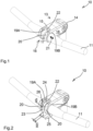
- 10 in its entirety designates a device for the torque-resistant connection of a bicycle handlebar 11 to the fork shaft 12 of a bicycle (not shown in more detail).
- the central component of the device is a handlebar stem 13, which is fixed at its one end 14, which is at the rear in the direction of travel, to the upper end of the fork shaft 12 in a known manner (not shown in more detail).
- the handlebar stem 13 is provided with a clamping device 16, which serves to clamp a central, cylindrical section 17 of the bicycle handlebar 11.
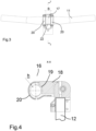
- the clamping device 16 has a receiving shell 19 formed on a base body 18 of the stem 13 and a clamping piece consisting of two clamping brackets 20, whereby both the receiving shell 19 and the two clamping brackets 20 each have an approximately semicircular cross-section on their inner sides that interact with the middle part 17 of the bicycle handlebar 11 and are thus adapted to the outer cross-section of the handlebar.
- the two clamping brackets 20 are connected to the base body 18 of the stem 13 with a total of four countersunk screws, for example hexagon socket screws, whereby the middle, cylindrical section 17 of the bicycle handlebar 11 is firmly clamped between the inner sides of the receiving shell 19 and the two clamping brackets 20, as is known.
- the two clamping brackets 20 are arranged in the axial direction 21 of the cylindrical section 17 at a distance B from one another, which in the preferred embodiment shown is greater than 15 mm, for example 20.5 mm.
- the invention provides that the receiving shell 19 is formed by two half-shells 19A, 19B spaced apart from one another, so that the cylindrical, middle section 17 of the handlebar 11 is only enclosed on its right and left outer areas by the two half-shells 19A, 19B and the respectively associated clamping brackets 20, while a free space 22 is formed between the half-shells and clamping bracket, in which the cylindrical section is not contacted by the clamping device when the handlebar is clamped, but remains freely accessible at least substantially over the entire circumference with a clear height h of at least approx. 3 mm, as can be seen in the Fig. 1 , 3 and especially Fig. 4 can be clearly seen.
- the width b of the clamp band 24 of the mounting clamp 23 is smaller than the dimension B of the free space 22 between the two half-shells 19 A, B and spacer rings 26 are placed on the handlebar 11 to the right and left of the clamp band 24, the thickness d of which is selected such that the total width of the clamp band of the mounting clamp and the two spacer rings (b+2*d) is only slightly smaller (20 mm in the embodiment) than the width dimension B of the free space 22, so that the mounting clamp is placed centered in the middle between the two half-shells and the clamp brackets connected to them.
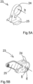
- the Figures 5A and 5B show two different versions of mounting clamps, as they can be used in the device according to the invention.
- the clamp according to Fig. 5A is in the Fig. 2 when mounted on the handlebar as described above.
- the mounting clamp according to Fig. 5B is provided with double clamp bands, which are spaced apart from each other at a distance corresponding to the width of the clamp band of the clamp Fig. 5A This makes it possible to arrange not only a single mounting clamp in the free space 22, as is the case in Fig. 2 shown, but a combination of two mounting clamps according to Fig. 5A and Fig. 5B , whereby the clamp bands of the clamps provided in twin arrangement according to Fig.
Landscapes
- Engineering & Computer Science (AREA)
- Mechanical Engineering (AREA)
- Steering Devices For Bicycles And Motorcycles (AREA)
- Clamps And Clips (AREA)
Description
- Die Erfindung betrifft eine Vorrichtung zur drehmomentfesten Verbindung eines Fahrzeuglenkers mit einem Gabelschaft eines zwei- oder dreirädrigen, insbesondere muskelbetätigten Fahrzeugs, insbesondere eines Fahrrads, mit einem mindestens eine Klemmeinrichtung aufweisenden Lenkervorbau, wobei die Klemmeinrichtung zur Einspannung eines zylindrischen Abschnitts des Fahrradlenkers eine an einem Vorbaugrundkörper ausgebildete, im Querschnitt etwa halbkreisförmige Aufnahmeschale sowie ein gegen die Aufnahmeschale anstellbares Klemmstück mit ebenfalls etwa halbkreisförmigen Querschnitt aufweist.
- Derartige Verbindungsvorrichtungen zwischen Lenker und Gabelschaft sind bei den meisten modernen Fahrrädern zu finden. Der Lenkervorbau kann dabei mit einem fest am Vorbaugrundkörper angeordneten Schaftende koaxial in den rohrförmigen Gabelschaft eingesteckt und in gewünschter Tiefenposition mittels eines Klemmkonus fixiert sein. Eine im Allgemeinen stabilere Verbindung bildet die sogenannte Ahead-Set Anordnung, bei der der Vorbau außen am oben aus dem Steuerrohr des Fahrradrahmens herausragenden Gabelschaftende angeklemmt ist, derart, dass der Vorbaugrundkörper vom Gabelschaft in Fahrtrichtung nach vorne vorragt. An seinem vorderen Ende ist der Vorbaugrundkörper mit der Klemmeinrichtung zur Montage des Lenkers versehen. Es ist für eine derartige Vorrichtung auch bekannt, den Vorbau an seinem hinteren, am Gabelschaft angeklemmten Bereich in seiner Neigung verstellbar auszugestalten, wozu zwischen dem Vorbaugrundkörper und einer Gabelklemmeinrichtung ein blockierbares Schwenkgelenk mit zwei Schwenklagern vorgesehen ist. Diese Schwenklager können im Wesentlichen aus zwei seitlich an der Gabelklemmeinrichtung vorkragenden, rohrförmigen Ansätzen und einer Klemmeinrichtung mit zwei die Ansätze umschließenden, mit Schrauben verspannbaren Haltebügeln bestehen, die zur Veränderung der Vorbauneigung gelöst und in gewünschter, neuer Position wieder arretiert werden können (
DE 201 21 831 U1 ). - Das Dokument
CN2889872Y zeigt Merkmale des unabhängigen Anspruchs 1. Aus dem Katalog "Supernova Lighting Systems 2016" ist eine Vorrichtung bekannt, bei der eine Montageschelle für eine Fahrradlampe im Freiraum zwischen den beiden Halbschalen der Aufnahmeschale sowie zwischen den Klemmbügeln der Montageschelle so angeordnet sein kann, dass sie den dort liegenden zylindrischen Abschnitt des Fahrradlenkers umfasst. - Die Ausgestaltung der Lenkerbefestigung mit einer etwa halbkreisförmigen Aufnahmeschale am Grundkörper und mit einem ebenfalls im Querschnitt etwa halbkreisförmigen Klemmstück, das mit Schrauben gegen die Aufnahmeschale anstellbar ist, wobei der mittlere zylindrische Abschnitt des Lenkers zwischen den beiden Komponenten der Klemmeinrichtung eingeklemmt und hierdurch relativ zur Fahrzeuggabel drehmomentfest arretiert wird, hat den Vorteil, dass der Lenker vom Vorbau demontiert werden kann, ohne dass hierfür Anbauteile wie Brems- oder Schaltgriffe, Griffüberzüge, Klingel o.dgl. abgebaut werden müssen. Zur Montage von Fahrzeugzubehörteilen wie z.B. einem Fahrradtacho, einer Fahrradlampe o.dgl. ist es bekannt, an dem Lenker eine für das jeweilige Zubehörteil geeignete Montageschelle anzubringen, an der das Zubehörteil dann entweder fest angeschlossen ist oder mit einem geeigneten Schnellverschluss befestigt werden kann. Es ist dabei oft gewünscht, das Zubehörteil möglichst an zentraler Stelle anzuordnen, also dort, wo z.B. ein Fahrradcomputer am besten im Blickfeld des Fahrers ist und eine Fahrradlampe den Fahrweg am besten ausleuchtet. Eine genau zentrische Anordnung am Fahrradlenker ist mit den bestehenden Verbindungssystemen allerdings bislang nicht ohne weiteres möglich, da an dieser Stelle die Klemmeinrichtung am vorderen Ende des Lenkervorbaus den zentralen, zylindrischen Abschnitt des Lenkers umschließt.
- Aufgabe der Erfindung ist es, eine Vorrichtung der eingangs genannten Art zu schaffen, bei der zwei Montageschellen für Fahrzeugzubehörelemente an möglichst zentraler Position unmittelbar am Fahrzeuglenker montiert werden können.
- Diese Aufgabe wird mit der Erfindung durch eine Vorrichtung gemäß Patentanspruch 1 gelöst.
- Die erfindungsgemäße Lösung erlaubt es, zwischen den beiden im Abstand voneinander am Lenker angreifenden Klemmbügeln und den damit zusammenwirkenden Halbschalen am Vorbaugrundkörper genau zentrisch mehrere Montageschellen für einen Fahrradtacho, eine Fahrradlampe oder ein anderes Zubehörelement zu montieren, denn der zwischen den Halbschalen ausgebildete, den zylindrischen Abschnitt des Lenkers nicht kontaktierende Freiraum bewirkt, dass der Lenker in diesem zylindrischen Abschnitt über seinen Umfang frei bleibt, die Befestigung der Schellen also nicht von der Klemmeinrichtung des Vorbaus behindert wird. Der Gestaltung liegt die Erkenntnis zugrunde, dass die mitunter großen, von der Klemmeinrichtung zwischen Lenker und Vorbau zu übertragenden Querkräfte und Biegemomente in den seitlich äußersten Bereichen der Klemmverbindung am besten übertragen werden und der zwischen den beiden Halbschalen bzw. den beiden Klemmbügeln liegende Bereich somit frei bleiben kann, ohne dass dies die Übertragung der Kräfte und Momente nennenswert beeinflusst. In einer ersten, vorteilhaften Ausführungsform der Erfindung kann die Anordnung so getroffen sein, dass die zwei Klemmbügel mittels mindestens einer, vorzugsweise in der Nähe des einen Endbereichs der Bügel angeschlossenen Verbindungsbrücke miteinander verbunden sind, die im Klemmzustand für den Durchlass der zwei Montageschellen im Radialabstand zu dem zylindrischen Abschnitt ist. Die Verbindungsbrücke fasst die beiden Klemmbügel zu einem gemeinsamen Bauteil zusammen, was die Montage am Lenker erleichtern kann. Da sich der Klemmbügel im Radialabstand vom Lenker befindet, können die Montageschellen ohne Probleme zwischen diesem und dem Bügel hindurch fassen.
- Alternativ ist es natürlich auch möglich, dass die Klemmbügel als voneinander separate, unverbundene Teile ausgeführt sind.
- Die Abmessung des Freiraums zwischen den beiden Halbschalen voneinander ist vorzugsweise an eine Breite der den zylindrischen Abschnitt umfassenden Montageschellen bzw. an eine Gesamtbreite der in dem Freiraum anzuordnenden Bauelemente (Schellenbänder, Distanzringe o.dgl.) angepasst. Sollen die zwei oder sogar drei Montageschellen zwischen den Halbschalen an zentraler Stelle am Lenker angeordnet werden, ist zweckmäßig deren Gesamtbreite, also die Summe der Breiten der einzelnen Schellen so bemessen, dass sie zwar ohne Zwang, aber auch nicht mit übermäßig viel Spiel zwischen die Halbschalen und die damit vorzugsweise mit Schrauben verspannten Klemmbügel passen. Die Anordnung ist erfindungsgemäß so getroffen, dass der zylindrische Abschnitt in dem Freiraum zwischen den beiden Halbschalen sowie zwischen den beiden Klemmbügeln von den Montageschellen für jeweils mindestens ein Fahrzeugzubehörelement vorzugsweise über die gesamte zur Verfügung stehende Freiraumabmessung umfasst ist.
- Bei den zwei Fahrzeugzubehörelementen, die mittels der Erfindung an zentraler Stelle am Lenker montiert werden können, kann es sich beispielsweise um Elemente aus der Gruppe Fahrradcomputer, Fahrradlampe, Lenkertaschenbefestigung, Schalthebel, Mobiltelefon und/oder GPS-Navigationsgerät handeln.
- Weitere Merkmale und Vorteile der Erfindung ergeben sich aus der nachfolgenden Beschreibung und der Zeichnung, worin eine bevorzugte Ausführungsform der Erfindung anhand eines Beispiels näher erläutert wird. Es zeigt:
-
Fig. 1 eine erfindungsgemäße Vorrichtung ohne Montageschelle in einer perspektivischen Darstellung; -
Fig. 2 die Vorrichtung mit einer Montageschelle in perspektivischer Darstellung; -
Fig. 3 den Gegenstand derFig. 1 in einer Vorderansicht; -
Fig. 4 der Gegenstand derFig. 1 in einem Schnitt längs der Linie X-X inFig. 3 ; und -
Fig. 5 A , B zwei Montageschellen, die bei der erfindungsgemäßen Vorrichtung in Kombination zum Einsatz gelangen können, in perspektivischen Darstellungen. - In der Zeichnung ist mit 10 in ihrer Gesamtheit eine Vorrichtung zur drehmomentfesten Verbindung eines Fahrradlenkers 11 mit dem Gabelschaft 12 eines nicht weiter dargestellten Fahrrads bezeichnet. Zentraler Bestandteil der Vorrichtung ist ein Lenkervorbau 13, der an seinem einen, in Fahrtrichtung hinteren Ende 14 in nicht weiter im Detail dargestellter, bekannter Weise am oberen Ende des Gabelschafts 12 festgelegt ist. An seinem vorderen Ende 15 ist der Lenkervorbau 13 mit einer Klemmeinrichtung 16 versehen, die zur Einspannung eines zentralen, zylindrischen Abschnitts 17 des Fahrradlenkers 11 dient.
- Die Klemmeinrichtung 16 hat eine an einem Grundkörper 18 des Vorbaus 13 ausgebildete Aufnahmeschale 19 sowie ein aus zwei Klemmbügeln 20 bestehendes Klemmstück, wobei sowohl die Aufnahmeschale 19 als auch die beiden Klemmbügel 20 an ihren mit dem Mittelteil 17 des Fahrradlenkers 11 zusammenwirkenden Innenseiten jeweils einen etwa halbkreisförmigen Querschnitt aufweisen und damit an den Außenquerschnitt des Lenkers angepasst sind. Die beiden Klemmbügel 20 sind mit dem Grundkörper 18 des Vorbaus 13 mit insgesamt vier versenkten Schrauben, beispielsweise Innensechskantschrauben verbunden, wobei der mittlere, zylindrische Abschnitt 17 des Fahrradlenkers 11 zwischen den Innenseiten der Aufnahmeschale 19 und der beiden Klemmbügel 20 fest eingespannt ist, wie dies bekannt ist.
- Man erkennt, dass die beiden Klemmbügel 20 in Achsrichtung 21 des zylindrischen Abschnitts 17 in einem Abstand B voneinander angeordnet sind, der bei dem gezeigten, bevorzugten Ausführungsbeispiel größer ist als 15 mm, zum Beispiel 20,5 mm betragen kann. In ähnlicher Weise ist erfindungsgemäß vorgesehen, dass die Aufnahmeschale 19 von zwei voneinander beanstandeten Halbschalen 19A, 19B gebildet wird, so, dass der zylindrische, mittlere Abschnitt 17 des Lenkers 11 nur an seinen rechts-und linksseitigen äußeren Bereichen von den beiden Halbschalen 19 A, 19 B und den jeweils zugeordneten Klemmbügeln 20 umschlossen wird, während sich zwischen den Halbschalen und Klemmbügel ein Freiraum 22 ausbildet, in welchem der zylindrische Abschnitt im Klemmzustand des Lenkers nicht von der Klemmeinrichtung kontaktiert wird, sondern zumindest im Wesentlichen über den gesamten Umfang mit einer lichten Höhe h von wenigstens ca. 3 mm frei zugänglich bleibt, wie man dies in den
Fig. 1 ,3 und insbesondereFig. 4 gut erkennen kann. - Wendet man sich nunmehr der
Fig. 2 zu, wird der besondere Vorteil der Konstruktion deutlich. Man erkennt, dass in dem zentralen Bereich zwischen den beiden Halbschalen 19 A,B und den damit verbundenen Klemmbügeln 20 aufgrund des dort über den gesamten Umfang des Lenkers 11 vorgesehenen Freiraums 22 ausreichend Platz für mindestens eine Montageschelle 23 geschaffen ist, die mit einem Schellenband 24 den Lenker 11 genau in seiner Mitte zwischen den beiden Klemmbügeln 20 und damit verbundenen Halbschalen 19A, 19B umschlingt und an der ein (nicht näher dargestelltes) Fahrzeugzubehörelement an einem Befestigungsschuh 25 angesteckt werden kann, beispielsweise eine Fahrradlampe. Bei dem gezeigten Ausführungsbeispiel ist die Breite b des Schellenbands 24 der Montageschelle 23 kleiner als die Abmessung B des Freiraums 22 zwischen den beiden Halbschalen 19 A,B und es sind rechts- und linksseitig des Schellenbands 24 auf den Lenker 11 Distanzringe 26 aufgesteckt, deren Dicke d so gewählt ist, dass die Gesamtbreite des Schellenbands der Montageschelle und der beiden Distanzringe (b+2*d) nur geringfügig kleiner (im Ausführungsbeispiel 20 mm) ist als die Breitenabmessung B des Freiraums 22, so dass die Montageschelle zentriert in der Mitte zwischen den beiden Halbschalen und den damit verbundenen Klemmbügeln platziert ist. - Die
Figuren 5A und 5B zeigen zwei verschiedene Versionen von Montageschellen, wie sie bei der erfindungsgemäßen Vorrichtung zum Einsatz kommen können. Die Schelle gemäßFig. 5A ist in derFig. 2 im am Lenker montierten Zustand wie vorstehend beschrieben dargestellt. Die Montageschelle gemäßFig. 5B ist mit doppelten Schellenbändern versehen, die in einem Abstand voneinander liegen, der der Breite des Schellenbands der Schelle nachFig. 5A entspricht. Somit besteht die Möglichkeit, in dem Freiraum 22 nicht nur eine einzelne Montageschelle anzuordnen, wie dies inFig. 2 gezeigt ist, sondern eine Kombination aus zwei Montageschellen gemäßFig. 5A und Fig. 5B , wobei die in Zwillingsanordnung vorgesehenen Schellenbänder der Schellen gemäßFig. 5B nicht nur die Halterung für das jeweilige Fahrzeugzusatzteil tragen, sondern zusätzlich auch die Funktion von Distanzstücken mit einer Dicke d übernehmen, die das einzelne, schmale Schellenband des Halters gemäßFig. 5A zwischen sich zentrieren. Die Anordnung mit zwei Montageschellen gestattet das Anbringen von zwei verschiedenen Fahrzeugzubehörelementen genau zentral in der Mitte des Lenkers, wobei dann vorzugsweise eines der Zubehörelemente oberhalb des Vorbaus 13 und das andere unterhalb des Vorbaus angeordnet ist. -
- 10
- Vorrichtung
- 11
- Fahrradlenker
- 12
- Gabelschaft
- 13
- Lenkervorbau
- 14
- hinteres Ende von 13
- 15
- vorderes Ende von 13
- 16
- Klemmeinrichtung
- 17
- zylindrischer Abschnitt von 11
- 18
- Grundkörper
- 19
- Aufnahmeschale A,B
- 20
- Klemmbügel
- 21
- Achsrichtung
- 22
- Freiraum
- h
- lichte Höhe
- 23
- Montageschelle
- 24
- Schellenband
- b
- Breite Schellenband,
- B
- Breite Freiraum
- 25
- Befestigungsschuh
- 26
- Distanzringe
- d
- Dicke von 26
Claims (5)
- Vorrichtung zur drehmomentfesten Verbindung eines Fahrzeuglenkers (11) mit einem Gabelschaft (12) eines zwei- oder dreirädrigen, insbesondere muskelbetätigten Fahrzeugs, insbesondere eines Fahrrads, mit einem mindestens eine Klemmeinrichtung (16) aufweisenden Lenkervorbau (13), wobei die Klemmeinrichtung (16) zur Einspannung eines zylindrischen Abschnitts (17) des Fahrradlenkers (11) eine an einem Vorbaugrundkörper (18) ausgebildete, im Querschnitt etwa halbkreisförmige Aufnahmeschale (19) sowie ein gegen die Aufnahmeschale anstellbares Klemmstück mit ebenfalls etwa halbkreisförmigen Querschnitt aufweist, wobei das Klemmstück zwei in Achsrichtung (21) des zylindrischen Abschnitts (17) voneinander beanstandete Klemmbügel (20) aufweist oder von diesen gebildet wird, wobei die Aufnahmeschale (19) von zwei entsprechend dem Abstand der Klemmbügel (20) voneinander beanstandeten Halbschalen (19A, 19B) gebildet wird, zwischen denen ein den zylindrischen Abschnitt (17) im Klemmzustand nicht kontaktierender Freiraum (22) ausgebildet ist, in dem eine Kombination von zwei den zylindrischen Abschnitt (17) wenigstens teilweise umschließenden Montageschellen (23) für zwei Fahrzeugzubehörelemente so aufgenommen ist, dass der zylindrische Abschnitt (17) in dem Freiraum (22) zwischen den beiden Halbschalen (19A,B) sowie zwischen den beiden Klemmbügeln (20) von der Kombination der beiden Montageschellen (23) für die Fahrzeugzubehörelemente umfasst ist, wobei eine erste der beiden Montageschellen mit einem einzelnen, schmalen Schellenband und eine zweite der beiden Montageschellen mit doppelten, in Zwillingsanordnung vorgesehenen Schellenbändern versehen ist, die in einem Abstand voneinander liegen, der der Breite des einzelnen schmalen Schellenbands der ersten Montageschelle entspricht, wobei die in Zwillingsanordnung vorgesehenen Schellenbänder der zweiten Montageschelle die Funktion von Distanzstücken mit einer Dicke (d) übernehmen, die das einzelne, schmale Schellenband der ersten Montageschelle zwischen sich zentrieren.
- Vorrichtung nach Anspruch 1, dadurch gekennzeichnet, dass die zwei Klemmbügel (20) mittels mindestens einer, vorzugsweise in der Nähe des einen Endbereichs der Bügel angeschlossenen Verbindungsbrücke miteinander verbunden sind, die im Klemmzustand für den Durchlass der Montageschellen (23) im Radialabstand zu dem zylindrischen Abschnitt (17) ist.
- Vorrichtung nach Anspruch 1, dadurch gekennzeichnet, dass die Klemmbügel (20) als voneinander separate, unverbundene Teile ausgeführt sind.
- Vorrichtung nach einem der Ansprüche 1 bis 3, dadurch gekennzeichnet, dass die Abmessung (B) des Freiraums (22) zwischen den beiden Halbschalen (19A,B) voneinander an eine Breite (b+2d) der den zylindrischen Abschnitt (17) umfassenden Montageschellen (23) angepasst ist.
- Vorrichtung nach einem der Ansprüche 1 bis 4, dadurch gekennzeichnet, dass die beiden Fahrzeugzubehörelemente Elemente aus der Gruppe Fahrradcomputer, Fahrradlampe, Lenkertaschenbefestigung, Schalthebel, Mobiltelefon und/oder GPS-Navigationsgerät sind.
Applications Claiming Priority (1)
| Application Number | Priority Date | Filing Date | Title |
|---|---|---|---|
| DE202019103437.8U DE202019103437U1 (de) | 2019-06-19 | 2019-06-19 | Vorrichtung zur drehmomentfesten Verbindung eines Fahrzeuglenkers mit einem Gabelschaft |
Publications (3)
| Publication Number | Publication Date |
|---|---|
| EP3753825A1 EP3753825A1 (de) | 2020-12-23 |
| EP3753825B1 EP3753825B1 (de) | 2022-01-26 |
| EP3753825B2 true EP3753825B2 (de) | 2024-12-18 |
Family
ID=71083342
Family Applications (1)
| Application Number | Title | Priority Date | Filing Date |
|---|---|---|---|
| EP20178916.1A Active EP3753825B2 (de) | 2019-06-19 | 2020-06-09 | Vorrichtung zur drehmomentfesten verbindung eines fahrzeuglenkers mit einem gabelschaft |
Country Status (2)
| Country | Link |
|---|---|
| EP (1) | EP3753825B2 (de) |
| DE (1) | DE202019103437U1 (de) |
Family Cites Families (6)
| Publication number | Priority date | Publication date | Assignee | Title |
|---|---|---|---|---|
| DE20121831U1 (de) | 2001-11-15 | 2003-08-07 | Wilhelm Humpert GmbH & Co. KG, 58739 Wickede | Verstellbarer Lenkervorbau für Zweiradfahrzeuge |
| US20060097474A1 (en) | 2004-11-10 | 2006-05-11 | Hsin Lung Accessories Co., Ltd. | Stem for a bicycle |
| CN2889872Y (zh) | 2006-03-20 | 2007-04-18 | 瑞奇设计公司 | 自行车把手立管锁固装置 |
| US8651350B2 (en) | 2011-10-19 | 2014-02-18 | Shimano Inc. | Accessory mounting structure |
| DE102012016907A1 (de) | 2012-08-27 | 2014-03-20 | Jochen Klieber | Lenkervorbau |
| DE102017111647A1 (de) | 2017-05-29 | 2018-11-29 | Kettler Alu-Rad GmbH | Fahrradbausatz mit einer Fahrradarmatur |
-
2019
- 2019-06-19 DE DE202019103437.8U patent/DE202019103437U1/de active Active
-
2020
- 2020-06-09 EP EP20178916.1A patent/EP3753825B2/de active Active
Also Published As
| Publication number | Publication date |
|---|---|
| DE202019103437U1 (de) | 2020-09-22 |
| EP3753825A1 (de) | 2020-12-23 |
| EP3753825B1 (de) | 2022-01-26 |
Similar Documents
| Publication | Publication Date | Title |
|---|---|---|
| DE102015202383B4 (de) | Kompressionsring und Steuersatz | |
| DE102015202483B4 (de) | Fahrradlenkervorbau | |
| EP2676750B1 (de) | Vorrichtung zum Führen von Schälgeräten | |
| DE3224589C2 (de) | Gepäckträger für ein Zweirad | |
| EP3409570B1 (de) | Fahrradbausatz mit einer fahrradarmatur | |
| EP3156313B1 (de) | Lenkerbefestigung für eine schalteinheit | |
| EP3560809B1 (de) | Vorbau-verbindungseinrichtung sowie fahrrad-element | |
| EP3753825B2 (de) | Vorrichtung zur drehmomentfesten verbindung eines fahrzeuglenkers mit einem gabelschaft | |
| EP2163349B1 (de) | Vorrichtung zum Spannen eines Federdämpferbeines | |
| DE19607640A1 (de) | Haltevorrichtung für Bremshebel an Rennrädern | |
| DE202022100922U1 (de) | Anordnung zum Verbinden eines Fahrradlenkers mit einer Fahrradgabel | |
| DE102015016027A1 (de) | Stützanordnung für vorderen Fahrradumwerfer | |
| EP2431268A1 (de) | Fahrrad-Lenkergriff | |
| EP4071037B1 (de) | Gepäckträger für ein zweirad | |
| EP3244076A1 (de) | Verbindungselement zur verbindung von haltestangen in einem bus | |
| WO2017092916A1 (de) | Funktionsintegrierte lenkeranordnung für ein motorrad | |
| DE202016104803U1 (de) | Haltevorrichtung für einen Radschützer eines Zweirads | |
| DE102015113793A1 (de) | Motorradlenker | |
| EP3786046A1 (de) | Vorbausystem | |
| EP2944554B1 (de) | Fahrrad mit einteiligem fahrradrahmen | |
| DE102018120062A1 (de) | Befestigungsvorrichtung und Verdrahtungsanordnung, die die Befestigungsvorrichtung umfasst | |
| DE102018133565B4 (de) | Motorradlenker und Motorrad | |
| DE2531462C3 (de) | Vorrichtung zum Halten eines ölrohrs an einem Kraftfahrzeuggetriebe | |
| DE102008052762A1 (de) | Lenker für Fahrzeuge, insbesondere für Motorräder | |
| DE102017106662B4 (de) | Radschützer für ein Vorderrad eines Zweirades mit einer einfedernden Vorderradgabel |
Legal Events
| Date | Code | Title | Description |
|---|---|---|---|
| PUAI | Public reference made under article 153(3) epc to a published international application that has entered the european phase |
Free format text: ORIGINAL CODE: 0009012 |
|
| STAA | Information on the status of an ep patent application or granted ep patent |
Free format text: STATUS: THE APPLICATION HAS BEEN PUBLISHED |
|
| AK | Designated contracting states |
Kind code of ref document: A1 Designated state(s): AL AT BE BG CH CY CZ DE DK EE ES FI FR GB GR HR HU IE IS IT LI LT LU LV MC MK MT NL NO PL PT RO RS SE SI SK SM TR |
|
| AX | Request for extension of the european patent |
Extension state: BA ME |
|
| STAA | Information on the status of an ep patent application or granted ep patent |
Free format text: STATUS: REQUEST FOR EXAMINATION WAS MADE |
|
| 17P | Request for examination filed |
Effective date: 20210623 |
|
| RBV | Designated contracting states (corrected) |
Designated state(s): AL AT BE BG CH CY CZ DE DK EE ES FI FR GB GR HR HU IE IS IT LI LT LU LV MC MK MT NL NO PL PT RO RS SE SI SK SM TR |
|
| GRAP | Despatch of communication of intention to grant a patent |
Free format text: ORIGINAL CODE: EPIDOSNIGR1 |
|
| STAA | Information on the status of an ep patent application or granted ep patent |
Free format text: STATUS: GRANT OF PATENT IS INTENDED |
|
| INTG | Intention to grant announced |
Effective date: 20210818 |
|
| GRAS | Grant fee paid |
Free format text: ORIGINAL CODE: EPIDOSNIGR3 |
|
| GRAA | (expected) grant |
Free format text: ORIGINAL CODE: 0009210 |
|
| STAA | Information on the status of an ep patent application or granted ep patent |
Free format text: STATUS: THE PATENT HAS BEEN GRANTED |
|
| AK | Designated contracting states |
Kind code of ref document: B1 Designated state(s): AL AT BE BG CH CY CZ DE DK EE ES FI FR GB GR HR HU IE IS IT LI LT LU LV MC MK MT NL NO PL PT RO RS SE SI SK SM TR |
|
| REG | Reference to a national code |
Ref country code: GB Ref legal event code: FG4D Free format text: NOT ENGLISH |
|
| REG | Reference to a national code |
Ref country code: CH Ref legal event code: EP |
|
| REG | Reference to a national code |
Ref country code: AT Ref legal event code: REF Ref document number: 1465075 Country of ref document: AT Kind code of ref document: T Effective date: 20220215 |
|
| REG | Reference to a national code |
Ref country code: IE Ref legal event code: FG4D Free format text: LANGUAGE OF EP DOCUMENT: GERMAN |
|
| REG | Reference to a national code |
Ref country code: DE Ref legal event code: R096 Ref document number: 502020000594 Country of ref document: DE |
|
| REG | Reference to a national code |
Ref country code: NL Ref legal event code: FP |
|
| REG | Reference to a national code |
Ref country code: LT Ref legal event code: MG9D |
|
| PG25 | Lapsed in a contracting state [announced via postgrant information from national office to epo] |
Ref country code: SE Free format text: LAPSE BECAUSE OF FAILURE TO SUBMIT A TRANSLATION OF THE DESCRIPTION OR TO PAY THE FEE WITHIN THE PRESCRIBED TIME-LIMIT Effective date: 20220126 Ref country code: RS Free format text: LAPSE BECAUSE OF FAILURE TO SUBMIT A TRANSLATION OF THE DESCRIPTION OR TO PAY THE FEE WITHIN THE PRESCRIBED TIME-LIMIT Effective date: 20220126 Ref country code: PT Free format text: LAPSE BECAUSE OF FAILURE TO SUBMIT A TRANSLATION OF THE DESCRIPTION OR TO PAY THE FEE WITHIN THE PRESCRIBED TIME-LIMIT Effective date: 20220526 Ref country code: NO Free format text: LAPSE BECAUSE OF FAILURE TO SUBMIT A TRANSLATION OF THE DESCRIPTION OR TO PAY THE FEE WITHIN THE PRESCRIBED TIME-LIMIT Effective date: 20220426 Ref country code: LT Free format text: LAPSE BECAUSE OF FAILURE TO SUBMIT A TRANSLATION OF THE DESCRIPTION OR TO PAY THE FEE WITHIN THE PRESCRIBED TIME-LIMIT Effective date: 20220126 Ref country code: HR Free format text: LAPSE BECAUSE OF FAILURE TO SUBMIT A TRANSLATION OF THE DESCRIPTION OR TO PAY THE FEE WITHIN THE PRESCRIBED TIME-LIMIT Effective date: 20220126 Ref country code: ES Free format text: LAPSE BECAUSE OF FAILURE TO SUBMIT A TRANSLATION OF THE DESCRIPTION OR TO PAY THE FEE WITHIN THE PRESCRIBED TIME-LIMIT Effective date: 20220126 Ref country code: BG Free format text: LAPSE BECAUSE OF FAILURE TO SUBMIT A TRANSLATION OF THE DESCRIPTION OR TO PAY THE FEE WITHIN THE PRESCRIBED TIME-LIMIT Effective date: 20220426 |
|
| PG25 | Lapsed in a contracting state [announced via postgrant information from national office to epo] |
Ref country code: PL Free format text: LAPSE BECAUSE OF FAILURE TO SUBMIT A TRANSLATION OF THE DESCRIPTION OR TO PAY THE FEE WITHIN THE PRESCRIBED TIME-LIMIT Effective date: 20220126 Ref country code: LV Free format text: LAPSE BECAUSE OF FAILURE TO SUBMIT A TRANSLATION OF THE DESCRIPTION OR TO PAY THE FEE WITHIN THE PRESCRIBED TIME-LIMIT Effective date: 20220126 Ref country code: GR Free format text: LAPSE BECAUSE OF FAILURE TO SUBMIT A TRANSLATION OF THE DESCRIPTION OR TO PAY THE FEE WITHIN THE PRESCRIBED TIME-LIMIT Effective date: 20220427 Ref country code: FI Free format text: LAPSE BECAUSE OF FAILURE TO SUBMIT A TRANSLATION OF THE DESCRIPTION OR TO PAY THE FEE WITHIN THE PRESCRIBED TIME-LIMIT Effective date: 20220126 |
|
| PG25 | Lapsed in a contracting state [announced via postgrant information from national office to epo] |
Ref country code: IS Free format text: LAPSE BECAUSE OF FAILURE TO SUBMIT A TRANSLATION OF THE DESCRIPTION OR TO PAY THE FEE WITHIN THE PRESCRIBED TIME-LIMIT Effective date: 20220526 |
|
| REG | Reference to a national code |
Ref country code: DE Ref legal event code: R026 Ref document number: 502020000594 Country of ref document: DE |
|
| PLBI | Opposition filed |
Free format text: ORIGINAL CODE: 0009260 |
|
| PG25 | Lapsed in a contracting state [announced via postgrant information from national office to epo] |
Ref country code: SM Free format text: LAPSE BECAUSE OF FAILURE TO SUBMIT A TRANSLATION OF THE DESCRIPTION OR TO PAY THE FEE WITHIN THE PRESCRIBED TIME-LIMIT Effective date: 20220126 Ref country code: SK Free format text: LAPSE BECAUSE OF FAILURE TO SUBMIT A TRANSLATION OF THE DESCRIPTION OR TO PAY THE FEE WITHIN THE PRESCRIBED TIME-LIMIT Effective date: 20220126 Ref country code: RO Free format text: LAPSE BECAUSE OF FAILURE TO SUBMIT A TRANSLATION OF THE DESCRIPTION OR TO PAY THE FEE WITHIN THE PRESCRIBED TIME-LIMIT Effective date: 20220126 Ref country code: EE Free format text: LAPSE BECAUSE OF FAILURE TO SUBMIT A TRANSLATION OF THE DESCRIPTION OR TO PAY THE FEE WITHIN THE PRESCRIBED TIME-LIMIT Effective date: 20220126 Ref country code: DK Free format text: LAPSE BECAUSE OF FAILURE TO SUBMIT A TRANSLATION OF THE DESCRIPTION OR TO PAY THE FEE WITHIN THE PRESCRIBED TIME-LIMIT Effective date: 20220126 Ref country code: CZ Free format text: LAPSE BECAUSE OF FAILURE TO SUBMIT A TRANSLATION OF THE DESCRIPTION OR TO PAY THE FEE WITHIN THE PRESCRIBED TIME-LIMIT Effective date: 20220126 |
|
| PLAX | Notice of opposition and request to file observation + time limit sent |
Free format text: ORIGINAL CODE: EPIDOSNOBS2 |
|
| 26 | Opposition filed |
Opponent name: WALLINGER RICKER SCHLOTTER TOSTMANN Effective date: 20221021 |
|
| PG25 | Lapsed in a contracting state [announced via postgrant information from national office to epo] |
Ref country code: AL Free format text: LAPSE BECAUSE OF FAILURE TO SUBMIT A TRANSLATION OF THE DESCRIPTION OR TO PAY THE FEE WITHIN THE PRESCRIBED TIME-LIMIT Effective date: 20220126 |
|
| PG25 | Lapsed in a contracting state [announced via postgrant information from national office to epo] |
Ref country code: MC Free format text: LAPSE BECAUSE OF FAILURE TO SUBMIT A TRANSLATION OF THE DESCRIPTION OR TO PAY THE FEE WITHIN THE PRESCRIBED TIME-LIMIT Effective date: 20220126 |
|
| PG25 | Lapsed in a contracting state [announced via postgrant information from national office to epo] |
Ref country code: SI Free format text: LAPSE BECAUSE OF FAILURE TO SUBMIT A TRANSLATION OF THE DESCRIPTION OR TO PAY THE FEE WITHIN THE PRESCRIBED TIME-LIMIT Effective date: 20220126 |
|
| PLBB | Reply of patent proprietor to notice(s) of opposition received |
Free format text: ORIGINAL CODE: EPIDOSNOBS3 |
|
| PG25 | Lapsed in a contracting state [announced via postgrant information from national office to epo] |
Ref country code: IE Free format text: LAPSE BECAUSE OF NON-PAYMENT OF DUE FEES Effective date: 20220609 |
|
| PG25 | Lapsed in a contracting state [announced via postgrant information from national office to epo] |
Ref country code: IT Free format text: LAPSE BECAUSE OF FAILURE TO SUBMIT A TRANSLATION OF THE DESCRIPTION OR TO PAY THE FEE WITHIN THE PRESCRIBED TIME-LIMIT Effective date: 20220126 |
|
| PG25 | Lapsed in a contracting state [announced via postgrant information from national office to epo] |
Ref country code: MK Free format text: LAPSE BECAUSE OF FAILURE TO SUBMIT A TRANSLATION OF THE DESCRIPTION OR TO PAY THE FEE WITHIN THE PRESCRIBED TIME-LIMIT Effective date: 20220126 Ref country code: CY Free format text: LAPSE BECAUSE OF FAILURE TO SUBMIT A TRANSLATION OF THE DESCRIPTION OR TO PAY THE FEE WITHIN THE PRESCRIBED TIME-LIMIT Effective date: 20220126 |
|
| PLAB | Opposition data, opponent's data or that of the opponent's representative modified |
Free format text: ORIGINAL CODE: 0009299OPPO |
|
| PG25 | Lapsed in a contracting state [announced via postgrant information from national office to epo] |
Ref country code: HU Free format text: LAPSE BECAUSE OF FAILURE TO SUBMIT A TRANSLATION OF THE DESCRIPTION OR TO PAY THE FEE WITHIN THE PRESCRIBED TIME-LIMIT; INVALID AB INITIO Effective date: 20200609 |
|
| R26 | Opposition filed (corrected) |
Opponent name: WALLINGER RICKER SCHLOTTER TOSTMANN Effective date: 20221021 |
|
| PG25 | Lapsed in a contracting state [announced via postgrant information from national office to epo] |
Ref country code: MT Free format text: LAPSE BECAUSE OF FAILURE TO SUBMIT A TRANSLATION OF THE DESCRIPTION OR TO PAY THE FEE WITHIN THE PRESCRIBED TIME-LIMIT Effective date: 20220126 |
|
| PUAH | Patent maintained in amended form |
Free format text: ORIGINAL CODE: 0009272 |
|
| STAA | Information on the status of an ep patent application or granted ep patent |
Free format text: STATUS: PATENT MAINTAINED AS AMENDED |
|
| 27A | Patent maintained in amended form |
Effective date: 20241218 |
|
| AK | Designated contracting states |
Kind code of ref document: B2 Designated state(s): AL AT BE BG CH CY CZ DE DK EE ES FI FR GB GR HR HU IE IS IT LI LT LU LV MC MK MT NL NO PL PT RO RS SE SI SK SM TR |
|
| REG | Reference to a national code |
Ref country code: DE Ref legal event code: R102 Ref document number: 502020000594 Country of ref document: DE |
|
| REG | Reference to a national code |
Ref country code: NL Ref legal event code: FP |
|
| PGFP | Annual fee paid to national office [announced via postgrant information from national office to epo] |
Ref country code: DE Payment date: 20250515 Year of fee payment: 6 |
|
| PGFP | Annual fee paid to national office [announced via postgrant information from national office to epo] |
Ref country code: GB Payment date: 20250620 Year of fee payment: 6 |
|
| PGFP | Annual fee paid to national office [announced via postgrant information from national office to epo] |
Ref country code: NL Payment date: 20250618 Year of fee payment: 6 Ref country code: LU Payment date: 20250617 Year of fee payment: 6 Ref country code: BE Payment date: 20250617 Year of fee payment: 6 |
|
| PGFP | Annual fee paid to national office [announced via postgrant information from national office to epo] |
Ref country code: FR Payment date: 20250618 Year of fee payment: 6 |
|
| PGFP | Annual fee paid to national office [announced via postgrant information from national office to epo] |
Ref country code: AT Payment date: 20250616 Year of fee payment: 6 |
|
| PGFP | Annual fee paid to national office [announced via postgrant information from national office to epo] |
Ref country code: CH Payment date: 20250701 Year of fee payment: 6 |
|
| PG25 | Lapsed in a contracting state [announced via postgrant information from national office to epo] |
Ref country code: TR Free format text: LAPSE BECAUSE OF FAILURE TO SUBMIT A TRANSLATION OF THE DESCRIPTION OR TO PAY THE FEE WITHIN THE PRESCRIBED TIME-LIMIT Effective date: 20220126 |