EP3753801B1 - Überwachungssystem für eine infrastruktur und/oder ein fahrzeug mit ereigniserkennung - Google Patents
Überwachungssystem für eine infrastruktur und/oder ein fahrzeug mit ereigniserkennung Download PDFInfo
- Publication number
- EP3753801B1 EP3753801B1 EP19180725.4A EP19180725A EP3753801B1 EP 3753801 B1 EP3753801 B1 EP 3753801B1 EP 19180725 A EP19180725 A EP 19180725A EP 3753801 B1 EP3753801 B1 EP 3753801B1
- Authority
- EP
- European Patent Office
- Prior art keywords
- sensor
- module
- event
- sensor data
- data
- Prior art date
- Legal status (The legal status is an assumption and is not a legal conclusion. Google has not performed a legal analysis and makes no representation as to the accuracy of the status listed.)
- Active
Links
Images
Classifications
-
- B—PERFORMING OPERATIONS; TRANSPORTING
- B61—RAILWAYS
- B61L—GUIDING RAILWAY TRAFFIC; ENSURING THE SAFETY OF RAILWAY TRAFFIC
- B61L15/00—Indicators provided on the vehicle or train for signalling purposes
- B61L15/0081—On-board diagnosis or maintenance
-
- G—PHYSICS
- G07—CHECKING-DEVICES
- G07C—TIME OR ATTENDANCE REGISTERS; REGISTERING OR INDICATING THE WORKING OF MACHINES; GENERATING RANDOM NUMBERS; VOTING OR LOTTERY APPARATUS; ARRANGEMENTS, SYSTEMS OR APPARATUS FOR CHECKING NOT PROVIDED FOR ELSEWHERE
- G07C5/00—Registering or indicating the working of vehicles
- G07C5/008—Registering or indicating the working of vehicles communicating information to a remotely located station
-
- B—PERFORMING OPERATIONS; TRANSPORTING
- B61—RAILWAYS
- B61L—GUIDING RAILWAY TRAFFIC; ENSURING THE SAFETY OF RAILWAY TRAFFIC
- B61L27/00—Central railway traffic control systems; Trackside control; Communication systems specially adapted therefor
- B61L27/50—Trackside diagnosis or maintenance, e.g. software upgrades
- B61L27/53—Trackside diagnosis or maintenance, e.g. software upgrades for trackside elements or systems, e.g. trackside supervision of trackside control system conditions
-
- B—PERFORMING OPERATIONS; TRANSPORTING
- B61—RAILWAYS
- B61L—GUIDING RAILWAY TRAFFIC; ENSURING THE SAFETY OF RAILWAY TRAFFIC
- B61L27/00—Central railway traffic control systems; Trackside control; Communication systems specially adapted therefor
- B61L27/50—Trackside diagnosis or maintenance, e.g. software upgrades
- B61L27/57—Trackside diagnosis or maintenance, e.g. software upgrades for vehicles or trains, e.g. trackside supervision of train conditions
-
- G—PHYSICS
- G07—CHECKING-DEVICES
- G07C—TIME OR ATTENDANCE REGISTERS; REGISTERING OR INDICATING THE WORKING OF MACHINES; GENERATING RANDOM NUMBERS; VOTING OR LOTTERY APPARATUS; ARRANGEMENTS, SYSTEMS OR APPARATUS FOR CHECKING NOT PROVIDED FOR ELSEWHERE
- G07C5/00—Registering or indicating the working of vehicles
- G07C5/08—Registering or indicating performance data other than driving, working, idle, or waiting time, with or without registering driving, working, idle or waiting time
- G07C5/0816—Indicating performance data, e.g. occurrence of a malfunction
- G07C5/0825—Indicating performance data, e.g. occurrence of a malfunction using optical means
-
- G—PHYSICS
- G07—CHECKING-DEVICES
- G07C—TIME OR ATTENDANCE REGISTERS; REGISTERING OR INDICATING THE WORKING OF MACHINES; GENERATING RANDOM NUMBERS; VOTING OR LOTTERY APPARATUS; ARRANGEMENTS, SYSTEMS OR APPARATUS FOR CHECKING NOT PROVIDED FOR ELSEWHERE
- G07C5/00—Registering or indicating the working of vehicles
- G07C5/08—Registering or indicating performance data other than driving, working, idle, or waiting time, with or without registering driving, working, idle or waiting time
- G07C5/0816—Indicating performance data, e.g. occurrence of a malfunction
- G07C5/0833—Indicating performance data, e.g. occurrence of a malfunction using audio means
-
- G—PHYSICS
- G07—CHECKING-DEVICES
- G07C—TIME OR ATTENDANCE REGISTERS; REGISTERING OR INDICATING THE WORKING OF MACHINES; GENERATING RANDOM NUMBERS; VOTING OR LOTTERY APPARATUS; ARRANGEMENTS, SYSTEMS OR APPARATUS FOR CHECKING NOT PROVIDED FOR ELSEWHERE
- G07C5/00—Registering or indicating the working of vehicles
- G07C5/08—Registering or indicating performance data other than driving, working, idle, or waiting time, with or without registering driving, working, idle or waiting time
- G07C5/10—Registering or indicating performance data other than driving, working, idle, or waiting time, with or without registering driving, working, idle or waiting time using counting means or digital clocks
-
- G—PHYSICS
- G08—SIGNALLING
- G08B—SIGNALLING OR CALLING SYSTEMS; ORDER TELEGRAPHS; ALARM SYSTEMS
- G08B23/00—Alarms responsive to unspecified undesired or abnormal conditions
Definitions
- the invention relates to a surveillance and/or maintenance system, in particular a modular surveillance and/or maintenance system, for an infrastructure such as a train station, an airport, a store or another public space and/or for a vehicle such as a train, an airplane or a ship with event detection.
- a surveillance system comprises at least two sensor modules configured to collect or record respective sensor data from a respective associated sensor such as a camera, microphone, or another sensor providing the sensor data, and at least one analysis module configured to access the sensor data.
- JP 2002 247 562 A provides a monitoring camera system coping with a network by which a working rate equivalent to the one of a multiprocessor type computer can be realized.
- This monitoring camera system is provided with said network for transmitting image data outputted from a plurality of monitoring camera units, shared by a plurality of the monitoring cameras and a server for receiving the image data via the network.
- a plurality of the monitoring cameras is provided with a communication control part for setting a protocol corresponding to the network to the image data and the server is provided with a protocol control part for receiving the image data to which the protocol is set from the network.
- WO 2018/180311 A1 provides a technology for monitoring train doors for improving the accuracy of detection of trapping in vehicle doors.
- the server compares the difference between a static image, the reference image, from each monitoring camera of a normal state in which there is no trapping in vehicle doors, and a static image, an observation image, acquired in a prescribed acquisition time. If a difference is detected and hence trapping in the door is probable, this can be indicated on a monitor.
- US 2011/313671 A1 describes the use of ballast sensors to detect rock fall events in a vicinity of railway tracks or similar roadways or tracks.
- the ballast sensors are spaced apart from the tracks. Signals from the ballast sensors may be used to discriminate rock fall events from other types of events and to detect the hypocenter of a rock fall event.
- a group of sensors may be determined, for instance all triggered sensors whose start times are within a time window of the start time of the first sensor to trigger on a rock fall event.
- An iterative procedure is then used where a virtual group of potential hypocenters, that may be arranged on a grid with a given spacing, is boiled down to arrive at the actual hypocenter which may be most proximate to the sensor that triggers first.
- EP 3 042 823 A1 relates to a rail vehicle event analysis system configured to facilitate analysis of rail vehicle event records that correspond to rail vehicle events.
- rail vehicle operation information is received via output signals generated by sensors coupled with a rail vehicle, and a rail vehicle event is detected based on the output signals.
- information from two or more of the output signals generated during the rail vehicle event is associated to create a rail vehicle event record; and the information from the two or more output signals generated during the rail vehicle event is synchronized based on analysis of the information conveyed by the output signals by identifying and correlating corresponding phenomena in the first output signal and the second output signal during the rail vehicle event.
- the analysis system may comprise a graphical user interface by which a user can enter or select observations. These observations may be associated with the rail vehicle event record, and the observations may be filtered based on geo-fences. Geo-fences may be virtual boundaries that define physical areas where one or more rail vehicle events are permissible or are not permissible.
- US 2011/216200 A1 , D3 discloses a locomotive wireless video recorder and recording system for generating images taken from a rail vehicle, the system including a camera configured to generate video data associated with a rail vehicle, and a processor configured to control recording of video data according to at least one of a variable frame rate or a variable resolution based on operating conditions of the rail vehicle.
- One aspect relates to a surveillance and/or maintenance system for an infrastructure such as a train station, an airport, store, or another public space, for instance, and/or for a vehicle such as train, airplane, or a ship, for instance.
- the surveillance and/or maintenance system is a modular surveillance and/or maintenance system.
- a surveillance system may also be referred to as a monitoring system.
- the system comprises at least two sensor modules, each configured to collect or record respective sensor data from a respective sensor such as a camera, a microphone, or another sensor associated with the sensor module, with the sensor providing the sensor data.
- the sensors may also be or comprise sensor units with several sensors.
- the sensor modules are configured to provide the sensor data to a data network of the system which connects different modules of the system, for instance to an analysis module and/or a storage module (as specified below).
- said sensor modules can be considered as source modules, as they function as a source of the data in the network.
- the sensor modules are configured to provide the sensor data to the network with a time stamp, i.e. they are configured to add a time stamp to the sensor data.
- the sensor modules may be part of the same entity, such as the infrastructure to be monitored, or part of different entities. So, part of the sensor modules may be integrated in one entity, e.g. the infrastructure, and another part of the sensor modules may be integrated in one or more other entities, e.g. one or more vehicles.
- the sensor modules of different entities may be added and removed dynamically, i.e. during intended use, from the network and their respective sensor data may be accessed by the analysis module only when the sensor modules are part of the network.
- the system comprises at least one analysis module configured to access the sensor data of one, several, or all sensor modules.
- all sensor modules of the system can be accessed by the at least one analysis module.
- the analysis module may be configured to access the sensor data via the data network directly in (or from) the respective sensor modules or indirectly, that is, via a storage module where the sensor data of the sensor modules may be stored (which is described below).
- the analysis module may also comprise an access module that is configured to forward the accessed sensor data to another module, for instance a storage module and/or an output module.
- Such an access module can be considered as a distributing module that forwards the data from the designated analysis modules to one or more designated target modules, such as the storage module and/or output module mentioned above.
- the analysis module is configured to detect, in particular automatically detect, a given or pre-set event based on (first) sensor data of at least one (first) sensor module and to associate (second) sensor data of at least one other (second) sensor module with the event based on the time stamps of the sensor data of the at least one (first) sensor module and the at least one other (second) sensor module.
- the analysis module may be or comprise a computer running analyzing routines or algorithms on the sensor data.
- the analysis module may comprise one or more neural networks, which are particularly strong in computing associations and/or learning correlations.
- the analysis module may be a general analysis module for detecting and/or analyzing event belonging to a large variety of classes of events, or a specific analysis module, which is configured to detect or analyze events of a specific class of events such as fires, vehicle malfunctions, or abnormalities in passenger behavior.
- the analysis module might detect the earthquake as given event based on sensor data of one (first) sensor module with a vibration sensor, which can be referred to as first vibration sensor module. It might then, based on the time stamps of the sensor data, associate sensor data of another (second) sensor module with another vibration sensor as sensor, for instance. This associated sensor data can then, for instance, be used to confirm the detection of said event based on the first sensor data, here the earthquake.
- both the sensor data which the detection of the event is based on and the associated sensor data can be used to analyse the course and/or cause of the detected event.
- sensor data of an electric current sensor which has been recorded at the time of the fire or shortly before the fire, can be automatically associated with the event based on the time stamps of the sensor data. Consequently, the course and/or cause of the event can be analyzed with increase efficiency.
- an abnormally increased current at the time of or slightly prior to the fire can be identified as cause of the fire by a human supervisor without manually searching through all available sensor data.
- Said increased current at the time of or slightly prior to the fire can, of course, then also be identified as cause of the fire by an algorithm such as a neural network with reduced computational effort. Therefore, the surveillance system is suited also for large and complex infrastructures, be it with or without associated vehicles.
- the analysis module may be configured to forward the sensor data the event detection is based on, i.e. the first sensor data, and the associated sensor data, i.e. the second sensor data, to an output module.
- the output module is configured to output the data to a supervisor and may comprise a monitor and/or a loudspeaker for that purpose.
- the analysis module may, in particular, be configured to only forward the sensor data the event detection is based on as well as the associated sensor data, and not forward other, arbitrary sensor data, to the output module for presentation to the supervisor. This saves network resources and makes the monitoring more clear and effective.
- only the sensor data the event detection is based on as well as the associated sensor data may automatically be analyzed by an algorithm such as a neural network, and not the other, arbitrary sensor data in order to reduce computational effort.
- the described system gives the advantage that even in very large and/or complex infrastructures with the huge manifold of different as well as similar sensors and sensor data available, surveillance and/or maintenance can be performed in an improved and flexible way.
- the event- and time-stamp-based approach described above can be used as a basis for a surveillance system capable of learning.
- the associated sensor data and their corresponding sensor modules can be considered as candidates for future first sensor data, that is sensor data on which event detection may be based in the future.
- the sensor data of the corresponding candidate sensor modules may, in a subsequent time step, get used as one of the first sensor modules or even replace a first sensor module when event detection is done in the analysis module.
- Such a learning system can be realized by means of the known correlation-based learning, where correlation is regarded as causality given preset conditions or constraints are met.
- the above-mentioned neural networks are particularly useful in such a setting.
- the described surveillance system can be used for realization of a (self-)learning, i.e. supervised or unsupervised surveillance system, where suitable sensor data that correlate with an event are automatically picked, and event detection is optimized by relying on the picked sensor data, be it in addition or alternatively to the sensor data used for event detection before.
- a (self-)learning i.e. supervised or unsupervised surveillance system
- suitable sensor data that correlate with an event are automatically picked, and event detection is optimized by relying on the picked sensor data, be it in addition or alternatively to the sensor data used for event detection before.
- only sensor data with a time stamp indicating a time which differs from an event time of the event by less than a given or preset maximum time interval is associated with the event.
- the event time is determined by the timestamp or the time stamps of the sensor data the detection of the event is based on.
- only sensor data with time stamps prior to the event time may be associated with the event.
- only sensor data with time stamps after the event time may be associated with the event. This is useful, for instance, when studying the effect of an event such as an earthquake on a passenger flow in a station, for instance.
- the described conditions for the sensor data to be associated with the event may be referred to as temporal constraints.
- the analysis module may be configured to access the sensor data based on the timestamp. This is particularly useful, when the sensor data is the sensor data stored in a storage module (described below) in order to access only relevant sensor data.
- the analysis module may be configured to associate sensor data of the at least one other second sensor module with the event based on the time stamps of the sensor data and one or more additional criteria or constraints.
- the sensor data of the second sensor module in consideration may be analyzed in order to detect abnormalities or alike in the second sensor data, and be associated with the event only if an abnormality has been identified in, for instance, a given maximum time interval before the event time (further examples for the additional criteria are described below).
- the abnormality condition and the like may be referred to as content-wise constraint.
- such content-wise constraint can be learnt by the system. This may be achieved by unsupervised learning, where the statistic nature of some characteristics of the sensor data, e.g. a rarity of the respective characteristic, is used.
- the analysis module is configured to associate the sensor data of the second sensor module with the event also based on a spatial relation between a location of the sensor associated with the first sensor module and a location of the sensor associated with the second sensor module.
- the additional criterion is the spatial relation and may be referred to as spatial constraint.
- the spatial relation may be given or preset by a user, for instance, or automatically determined, for instance via meta data contained in the sensor data, such as a GPS information tag.
- the spatial relation may include other characteristics, such as the sensors being separated by a wall, being in the same room, etc.
- only sensor data of or from the sensor modules with the associated sensor within a given (maximum) spatial distance from the associated sensor of the first sensor module may be associated or correlated with the event.
- only sensor data of or from the sensor modules with the associated sensor outside of a given (minimum) spatial distance from the associated sensor of the first sensor module may be associated or correlated with the event.
- only sensor data of or from the sensor modules with the associated sensor in a given range of distance from the associated sensor of the first sensor module may be associated or correlated with the event. It depends on the event/class of event whether a minimum or maximum spatial distance of the sensor modules is chosen as additional criterion.
- the different constraints may be used in different combinations.
- different combinations of constraints may be selected for different events or event classes.
- the constraints or combinations of constraints appropriate for the event may also be learned by the system, be it by supervised learning methods or unsupervised learning methods.
- the analysis module is configured to verify the detection of the event based on the sensor data associated with the event and/or the sensor data of the first sensor module. So, in particular also a combination of the sensor data of the second sensor module with the sensor data of the first sensor module may be used for event verification. For instance, if a vibration detector associated with the first sensor module detects a vibration pattern which is typical for an earthquake, another vibration detector associated with the second sensor module should to detect a similar pattern. If only one single vibration sensor module detects said typical vibration pattern, it could well be a false alarm due to some other influence on the first vibration detector module. In this verification process, it is highly advantageous that the sensor data are provided with the time stamps so that the verification can be particularly exact and precise. In this setting, it is also particularly useful if the timestamp is based on a common time signal provided to the different sensor modules (described below).
- the analysis module is configured to classify and/or verify the detected event according to given event classes, and, based on the class the detected event is classified to belong to, associate sensor data of a predetermined sensor module and/or sensor data of a predetermined type of sensor modules with the event.
- the analysis module may also be configured to associate the sensor data of the predetermined sensor module and/or the sensor data of the predetermined type of sensor modules with the class of event to improve event classification in the future.
- the event classes may be one or more of the following: global event, local event, dangerous event, maintenance event, rapid evolving event, slow evolving event, energy induced event, air environmental event.
- the analysis module is configured to, based on the detected event and/or the class of the detected event, trigger an alarm output to an operator or the public by a corresponding output module. For instance, if a local event is not harmful, only a supervisor may be alerted by triggering the alarm. A global event with potential threat to the public, such as an earthquake, may be announced to the public by triggering the alarm.
- This further improves the surveillance performance of the system and the security of the monitored infrastructure and/or vehicle.
- the analysis module may be configured to forward the sensor data to an output module, in particular an output module with a monitor and/or a loudspeaker.
- the sensor data may provide comprise second and/or first sensor data.
- the analysis module is configured to, when an event is detected automatically access the sensor data associated with the event directly and/or by a storage module (preferably based on the timestamp) and forward the associate sensor data to an output module.
- the associated sensor data may be forwarded to the output module along with the first sensor data, and, for instance, displayed in parallel by the output module.
- the analysis module may be configured to forward the sensor data of or from the different sensor modules to the output module in a synchronized way. This means sensor data with the same (or, according to a pre-set criterion such as a maximum difference: similar) timestamp will be forwarded together and output, for instance displayed, at the same time.
- the analysis module may be configured to remotely configure another module, for instance one or more of the sensor modules or the storage module so as forward the sensor data directly to the output module.
- the analysis module may be configured to evaluate respective (relative and/or absolute) time lags of the sensor data stemming from the different sensor modules, and delay forwarding sensor data of at least one of the sensor modules based on the evaluated time lags, in particular based on the maximum time lag evaluated. So, the analysis module may be configured to forward sensor data from different sensor modules with a respective timestamp corresponding to the same point in time, which arrived at the analysis module at different times, that is, with different (relative) time lags, together and/or synchronized.
- the module evaluating the time lag may evaluate an absolute time lag of the sensor data. This can, for instance, be realized by providing the respective module with the common time signal and comparing the time stamps of the sensor data with the common time signal reflecting global time.
- all sensor data that is forwarded by the analysis module may be forwarded together and/or synchronized.
- a subset of sensor data may be forwarded in an unsynchronized way, for instance the moment it arrives in the analysis module.
- unsynchronized sensor data is, for instance, output to a human operator, it is preferably marked as unsynchronized. This gives the advantage that the data which is prioritized to be observed with less delay than to be synchronized with other data can be shown with minimal delay as required and without confusing the human operator.
- the sensor modules are of at least two qualitatively different types, where each type of sensor module is associated with a different type of sensor and is configured to collect a qualitatively different type of sensor data.
- each of the different types of sensor modules may be associated with at least one of the following sensors as respective sensor: camera sensor, multi-camera sensor, microphone sensor, multi-microphone sensor, temperature sensor, fire alarm sensor, smoke sensor, voltage sensor, power consumption sensor, door sensor, emergency button sensor, escalator load sensor, vehicular sensor, electronic current sensor, flow rate sensor, pressure sensor, rotational speed sensor, translational speed sensor, rotational acceleration sensor, translational acceleration sensor, vibration sensor, motion detection sensor, radar sensor, Hall sensor, ultrasonic sensor, GPS (which may include any global positioning system, GPS, GLONASS, Galileo or alike) sensor, load cell sensor (which may for instance be used as a force gauge), light barrier sensor.
- GPS which may include any global positioning system, GPS, GLONASS, Galileo or alike
- load cell sensor which may for instance be used as a force gauge
- one sensor module may collect sensor data from a camera sensor, which makes it a camera sensor module, while another sensor module may be associated with voltage sensor as respective sensor, which makes it a voltage sensor module, and so on.
- Said types of sensors and sensor modules have been proven particularly useful in surveillance and maintenance of infrastructures and/or vehicles, and thus are particularly advantageous.
- the sensor modules and/or output modules and/or analysis modules have a unified interface (or unified interfaces) and/or are configured to be exchangeable or replaceable, in particular exchangeable or replaceable during the operation of the system ("hot-pluggable").
- the sensor data can be encapsulated data, for instance in a so-called container format, where all sensor data has the same data format in spite of varying type of content.
- the analysis module and/or the storage module can handle the data without needing information about the content.
- the different modules for instance the sensor module of the vehicle and the sensor module of an infrastructure, may connect themselves via a wireless connection, for instance WLAN or Bluetooth.
- sensor modules may be upgraded or exchanged during the operation and/or without the necessity of changing hardware and/or software in the rest of the system.
- This exchangeability also enables the flexible integration of sensor modules of different entities such as an infrastructure and varying vehicles into the surveillance and/or maintenance system.
- the sensor module of the vehicle can be accessed (as a source module) by the analysis module of the infrastructure (as a target module), hence allowing the system to integrate vehicles when they enter the infrastructure and hence their state is relevant to the state of the infrastructure.
- the system comprises at least one storage module which is configured to store the sensor data of at least one sensor module.
- the at least one storage module is configured to store the sensor data of at least two sensor modules or all sensor modules.
- the at least one analysis module is configured to access the collected sensor data in the sensor module and/or the stored sensor data in the storage module. Obviously, the analysis module may access the sensor data in the sensor module and forward it to the storage module (and/or another module such as an output module), while a second analysis module may access the sensor data in the storage module, for instance.
- each sensor data stored in the storage module may comprise a plurality of sub-data, where each sub-data has a specific timestamp
- the analysis module is configured to, when accessing store sensor data in the storage module, access only sub-data with the timestamp that is specified for the particular accessing or a time stamp within a specified, i.e. preset range that is specified for the particular accessing.
- the sensor modules and/or the at least one analysis module and/or other at least one storage module can be configured remotely and/or dynamically during operation of the system as functioning surveillance system.
- an analysis module of a vehicle such as a train
- an infrastructure such as a train station
- the analysis module of the vehicle may be configured to forward sensor data of a different specific sensor module to the respective module located in the infrastructure.
- the sensor modules and/or the at least one analysis module and/or the at least one storage module can be configured to collect, respectively access, and/or store sensor data only in one or more preset time intervals and/or only with a data rate limited by a predetermined or preset maximum data rate.
- This preset time interval or preset maximum data rate may also be preset dynamically, for instance in dependence upon a network load.
- the preset time intervals may be determined by a maximum size of the sensor data corresponding to the pre-set time intervals, that is determined by the size of the sensor data forwarded for a certain period of time taken into account.
- a camera may be configured to transmit only every second collected or recorded image to a corresponding access module.
- the system comprises a clock module which is configured to provide a common time signal to at least one, preferably some or all sensor modules and/or the analysis module, where the time stamp of the sensor modules is based on the common time signal.
- the clock may also provide the common time signal to the at least one storage module, if present.
- the common time signal may contain time-zone information in order to avoid data synchronization confusion. This gives the advantage of further increased accuracy in processing the sensor data and analyzing the event.
- the clock module may be realized in one single, integrated hardware unit, but may also be realized by several distinct and/or distributed collaborating clock units.
- the collaborating clock units may also be cascaded.
- the collaborating clock units are synchronized.
- one clock module (or one clock unit of the clock module) may work as a source for an absolute-time signal by network time protocol (NTP) and another clock module (or another clock unit of the clock module) may work as a source for a sequentially numbered heart-beat-time signal by different protocol, where latter clock module (or unit) is synchronized to former clock module (or unit) through NTP.
- NTP network time protocol
- Another aspect relates to a method for surveilling or monitoring an infrastructure and/or a vehicle, with several method steps.
- One method step is collecting, by at least two sensor modules, respective sensor data from a respective sensor associated with the respective sensor module.
- Another method step is accessing, by at least one analysis module, the sensor data.
- the method further comprises the method step of providing, by the sensor modules, the sensor data with a time stamp.
- Another method step is detecting, by the analysis module, a given event based on sensor data of at least one (first) sensor module and to associate sensor data of at least one other (second) sensor module with the event based on the time stamps of the sensor data.
- Advantages and advantageous embodiments of the method correspond to advantages and advantageous embodiments of the surveillance and/or maintenance system.
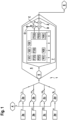
- FIG. 1 shows an exemplary embodiment of a surveillance system for an infrastructure and/or a vehicle.
- the surveillance system 1 of Fig. 1 comprises at least two, in the present example four sensor modules 2a-2d which are configured to collect respective sensor data I, F1, F2, V from respective associated sensors 3a-3d. So, for instance, the first sensor 2a collects or records respective sensor data I from the first sensor 3a, the second sensor module 2b collects sensor data F1 from the second sensor 3b et cetera.
- the system 1 has a current sensor module 2a, a first vibration frequency sensor module 2b, a second vibration frequency module 2c, and a video sensor module 2d.
- a clock module 4 provides a common time signal t to the sensor modules 2a-2d.
- the sensor modules 2a-2d are configured to provide the sensor data I, F1, F2, V with a corresponding timestamp. The timestamp is based on the common time signal and enhances accuracy and reliability of the surveillance system.
- the surveillance system 1 furthermore comprises an analysis module 5, which is configured to access the sensor data and to detect a given event based on sensor data of at least one sensor module and to associate, based on the time stamps of the respective sensor data, sensor data of at least one other sensor module with the event.
- the one sensor module and the other sensor module may generally be referred to as first and second sensor module and may be any sensor module of the system 1, not to be mixed with the first, second, third,.. sensor modules 2a-2d of the present embodiment. So, as described below, for instance the second sensor module 2b may be the first sensor module in the above meaning.
- the analysis module 5 comprises an access module 6 which is configured to access the time-stamped sensor data I t , F1 t , F2 t , V t from the respective sensors 2a-2d.
- the event detection and association of sensor data with each other is, in the present example, realized in a computation module 7.
- the computation module 7 is part of the analysis module 5.
- Access module 6 and computation module 7 may be realized as a separate software and/or hardware units, where, for instance, the access module 6 is located in a different location from the computation module 7.
- the analysis module 5 may also be configured to access the sensor data from a storage module instead of from the respective sensor modules to a 2 to the (not shown).
- the surveillance system 1 is configured to detect events in live sensor data, which may be referred to a "online” surveillance, where an infrastructure and/or vehicle is monitored during its intended use/operation.
- live sensor data which may be referred to a "online” surveillance
- the before mentioned accessing of sensor data stored in the storage module may be referred to as "off-line” surveillance or analysis, which is aimed at analyzing stored data well after, for example, hours, days or even weeks after a specific event (such as an accident) has happened with the purpose to analyze and understand the event better and potentially avoid such an event in the future.
- the analysis module 5 of Fig. 1 is configured to trigger an alarm output based on the detected event.
- the alarm output is output to an operator and/or the public by a corresponding output module 8.
- the analysis module 7 is configured to verify the detection of the event based on the sensor data associated with the event and the sensor data of the first sensor module, as described in the following.
- Fig. 1 this is illustrated by several sensor data packages I(1), I(2), I(3), F1(1), F1(2), F1(4), F2(1), F2(4), V(1), V(2), V(4) placed on a time axis t.
- the time axis t now exemplarily refers only to a limited number of points of time 1-4.
- data packages, I(1) F1(1), F2(1), and V(1) are available.
- the analysis module 5 detects a given event based on sensor data of one sensor of the sensor modules 2a-2d, for instance a frequency signature typical for an earthquake in the sensor data package F2(4) of the second frequency sensor module 2c.
- the event of an earthquake may be classified as belonging to a class of global events, which is thus, in the example at hand according to a pre-set rule stored in the analysis module 5, to be verified by sensor data of another, second sensor module of the same type as the initial sensor module.
- the sensor data to be associated with the event has to belong to the same time as the event time.
- the detected event is an earthquake and, accordingly, the sensor data to be associated with the event is predetermined as stemming from a specific sensor, here the frequency sensor 3b, the sensor data package V(4) is not associated with the event.
- the event is detected based on first sensor data, frequency sensor data F2 t in the case of the earthquake and video sensor data V t in case of the fire, of a corresponding first sensor module, the second frequency sensor module 2c or the camera sensor module 2d, respectively.
- Respective sensor data F1 t , I t of another sensor module 2b, 2a is associated with the event based on the time stamps of the sensor data I t , F1 t , F2 t , V t .
- the analysis module 5 of the present system is, in both cases, configured to verify the detection of the respective event based on the sensor data F1 t , I t associated with the event and, in particular, also of the sensor data F2 t , V t of the corresponding first sensor module, be it the first frequency sensor module 2c or the video sensor module 2d.
- the analysis module 5 is detecting D the event in the sensor data package F2(4) of the frequency sensor module 2c and verifying or confirming C the event based on the frequency sensor data F1, namely the frequency sensor data package F1(4), of the frequency sensor module 2b. So, in the present example, if verifying C gives a negative result, which is symbolized by N in the figure, the alarm output is not triggered and the process is terminated, processing/method step O. If, on the other hand, verifying C gives a positive result, which is symbolized by Y in the figure, the event is confirmed by the associated sensor data F1 and in a corresponding processing step Z, the alarm output is triggered.
- the confirmation step C is negative, and no output will be triggered (arrow N, processing step O).
- the frequency sensor package F1(4) shows the characteristic frequency signature indicating an earthquake just as the frequency package F2(4), the confirmation step C is positive and outputting the alarm by output module 8 is triggered (arrow Y, processing step Z).
- the surveillance system according to the depicted example is not limited to the configuration explained above, but serves only as illustrational example for the advantages such as enhanced reliability and enhanced automatic processing of sensor data stemming from many sensor modules in a large and/or complex infrastructure, with or without a vehicle.
Landscapes
- Engineering & Computer Science (AREA)
- Physics & Mathematics (AREA)
- General Physics & Mathematics (AREA)
- Mechanical Engineering (AREA)
- Health & Medical Sciences (AREA)
- Biomedical Technology (AREA)
- General Health & Medical Sciences (AREA)
- Business, Economics & Management (AREA)
- Emergency Management (AREA)
- Multimedia (AREA)
- Alarm Systems (AREA)
- Traffic Control Systems (AREA)
- Closed-Circuit Television Systems (AREA)
Claims (14)
- Überwachungssystem (1) für eine Infrastruktur und/oder ein Fahrzeug, umfassend- zumindest zwei Sensormodule (2a-2d), die konfiguriert sind, um jeweilige Sensordaten (I, F1, F2, V) von einem jeweiligen assoziierten Sensor (3a-3d) zu sammeln;- ein Analysemodul (5), das konfiguriert ist, um auf die Sensordaten (I, F1, F2, V) zuzugreifen, wobei- die Sensormodule (2a-2d) konfiguriert sind, um die Sensordaten (I, F1, F2, V) mit einem Zeitstempel bereitzustellen, und- das Analysemodul (5) konfiguriert ist, um ein gegebenes Ereignis basierend auf Sensordaten (I, F1, F2, V) von zumindest einem ersten Sensormodul (2a-2d) zu erkennen und um Sensordaten (I, F1, F2, V) von zumindest einem anderen zweiten Sensormodul (2a-2d) mit dem Ereignis basierend auf den Zeitstempeln der Sensordaten (I, F1, F2, V) zu assoziieren,wobeidas Analysemodul (5) konfiguriert ist, um die Sensordaten (I, F1, F2, V) des zweiten Sensormoduls (2a-2d) mit dem Ereignis basierend auf einer räumlichen Beziehung zwischen einem Standort des Sensors, der mit dem ersten Sensormodul (2a-2d) assoziiert ist, und einem Standort des Sensors, der mit dem zweiten Sensormodul (2a-2d) assoziiert ist, zu assoziieren,dadurch gekennzeichnet, dassdas Analysemodul konfiguriert ist, um abhängig von einer Klasse des erkannten Ereignisses entwedernur Sensordaten (I, F1, F2, V) von zweiten Sensormodulen (2a-2d) mit dem assoziierten Sensor innerhalb eines gegebenen räumlichen Abstands zu dem assoziierten Sensor des ersten Sensormoduls (2a-2d) werden mit dem Ereignis assoziiert; odernur Sensordaten (I, F1, F2, V) von zweiten Sensormodulen (2a-2d) mit dem assoziierten Sensor außerhalb eines gegebenen räumlichen Abstands zu dem assoziierten Sensor des ersten Sensormoduls (2a-2d) werden mit dem Ereignis assoziiert; odernur Sensordaten (I, F1, F2, V) von zweiten Sensormodulen (2a-2d) mit dem assoziierten Sensor in einem gegebenen Bereich von räumlichem Abstand zu dem assoziierten Sensor des ersten Sensormoduls (2a-2d) werden mit dem Ereignis assoziiert.
- System (1) nach Anspruch 1, dadurch gekennzeichnet, dass nur Sensordaten (I, F1, F2, V) mit einem Zeitstempel, der eine Zeit angibt, die sich von einer Ereigniszeit um weniger als ein gegebenes maximales Zeitintervall unterscheidet, mit dem Ereignis assoziiert werden, wobei die Ereigniszeit durch den Zeitstempel der Sensordaten (I, F1, F2, V) bestimmt wird, auf denen die Erkennung des Ereignisses basiert.
- System (1) nach einem der vorhergehenden Ansprüche, dadurch gekennzeichnet, dass die räumliche Beziehung eine Eigenschaft verschieden von einem Abstand der jeweiligen Sensoren der Sensormodule (2a-2d) umfasst, insbesondere eine Eigenschaft dafür, dass die Sensoren durch eine Wand getrennt sind und/oder eine Eigenschaft dafür, dass die Sensoren in demselben Raum sind.
- System (1) nach einem der vorhergehenden Ansprüche, dadurch gekennzeichnet, dass das Analysemodul (5) konfiguriert ist, um die Erkennung des Ereignisses basierend auf den Sensordaten (I, F1, F2, V) assoziiert mit dem Ereignis und/oder den Sensordaten (I, F1, F2, V) des ersten Sensormoduls (2a-2d) zu verifizieren (C).
- System (1) nach einem der vorhergehenden Ansprüche, dadurch gekennzeichnet, dass das Analysemodul (5) konfiguriert ist, um das erkannte Ereignis gemäß gegebenen Ereignisklassen zu klassifizieren und/oder zu verifizieren (C) und basierend auf der Klasse, in der das erkannte Ereignis als zugehörig klassifiziert ist, Sensordaten (I, F1, F2, V) eines vorbestimmten Sensormoduls (2a-2d) und/oder Sensordaten (I, F1, F2, V) eines vorbestimmten Typs von Sensormodulen (2a-2d) mit dem Ereignis zu assoziieren.
- System (1) nach einem der vorhergehenden Ansprüche, dadurch gekennzeichnet, dass das Analysemodul (5) konfiguriert ist, um basierend auf dem erkannten Ereignis und/oder der Klasse des erkannten Ereignisses eine Alarmausgabe an einen Bediener oder an die Öffentlichkeit durch ein entsprechendes Ausgabemodul (8) auszulösen.
- System (1) nach einem der vorhergehenden Ansprüche, dadurch gekennzeichnet, dass das Analysemodul (5) konfiguriert ist, um die Sensordaten (I, F1, F2, V) an ein Ausgabemodul (8), insbesondere ein Ausgabemodul (8) mit einem Monitor und/oder einem Lautsprecher, weiterzuleiten.
- System (1) nach dem vorhergehenden Anspruch, dadurch gekennzeichnet, dass das Analysemodul (5) konfiguriert ist, um, wenn ein Ereignis erkannt wird, automatisch auf die Sensordaten (I, F1, F2, V), die mit dem Ereignis assoziiert sind, zuzugreifen und die assoziierten Sensordaten (I, F1, F2, V) an das Ausgabemodul (8) weiterzuleiten.
- System (1) nach einem der Ansprüche 7 oder 8, dadurch gekennzeichnet, dass das Analysemodul (5) konfiguriert ist, um die Sensordaten (I, F1, F2, V) der verschiedenen Sensormodule (2a-2d) an das Ausgabemodul (8) auf eine synchronisierte Weise weiterzuleiten.
- System (1) nach einem der vorhergehenden Ansprüche, dadurch gekennzeichnet, dass die Sensormodule (2a-2d) von zumindest zwei verschiedenen Typen sind, wobei jeder Typ von Sensormodul (2a-2d) mit einem anderen Typ von Sensor (3a-3d) assoziiert ist und konfiguriert ist, um einen anderen Typ von Sensordaten (I, F1, F2, V) zu sammeln.
- System (1) nach Anspruch 10, dadurch gekennzeichnet, dass jeder der verschiedenen Typen von Sensormodulen (2a-2d) mit zumindest einem der folgenden Sensoren als jeweiliger Sensor (3a-3d) assoziiert ist: Kamerasensor, Mehrkamerasensor, Mikrofonsensor, Mehrmikrofonsensor, Temperatursensor, Feueralarmsensor, Rauchsensor, Spannungssensor, Stromverbrauchssensor, Türsensor, Notbodensensor, Rolltreppenlastsensor, Fahrzeuglastsensor, elektronischer Stromsensor, Durchflussratensensor, Drucksensor, Dreh- und/oder Translationsgeschwindigkeitssensor, Dreh- und/oder Translationsbeschleunigungssensor, Vibrationssensor, Bewegungserkennungssensor, Radarsensor, Hallsensor, Ultraschallsensor, GPS-Sensor, Lastzellensensor, Lichtschrankensensor.
- System (1) nach einem der vorhergehenden Ansprüche, gekennzeichnet durch zumindest ein Speichermodul, das konfiguriert ist, um auf die Sensordaten (I, F1, F2, V) der Sensormodule (2a-2d) zuzugreifen und diese zu speichern, wobei das zumindest eine Analysemodul (5) konfiguriert ist, um auf die Sensordaten (I, F1, F2, V) in dem Sensormodul (2a-2d) und/oder die Sensordaten (I, F1, F2, V) in dem Speichermodul zuzugreifen.
- System (1) nach einem der vorhergehenden Ansprüche, gekennzeichnet durch ein Uhrmodul (4), das konfiguriert ist, um ein gemeinsames Zeitsignal (t) an einige oder alle Sensormodule (2a-2d) und/oder das Analysemodul (5) bereitzustellen, wobei der Zeitstempel der Sensormodule (2a-2d) auf dem gemeinsamen Zeitsignal (t) basiert.
- Verfahren zum Überwachen einer Infrastruktur und/oder eines Fahrzeugs, mit den Verfahrensschritten:- Sammeln, durch zumindest zwei Sensormodule (2a-2d), von jeweiligen Sensordaten (I, F1, F2, V) von einem jeweiligen Sensor (3a-3d), der mit dem jeweiligen Sensormodul (2a-2d) assoziiert ist,- Zugreifen, durch zumindest ein Analysemodul (5), auf die Sensordaten (I, F1, F2, V);- Bereitstellen, durch die Sensormodule (2a-2d), der Sensordaten (I, F1, F2, V) mit einem Zeitstempel,- Erkennen (D), durch das Analysemodul (5), eines gegebenen Ereignisses basierend auf Sensordaten (I, F1, F2, V) von zumindest einem ersten Sensormodul (2a-2d) und un Sensordaten (I, F1, F2, V) von zumindest einem anderen zweiten Sensormodul (2a-2d) mit dem Ereignis basierend auf den Zeitstempeln der Sensordaten (I, F1, F2, V) zu assoziieren,- Assoziieren, durch das Analysemodul (5), der Sensordaten (I, F1, F2, V) des zweiten Sensormoduls (2a-2d) mit dem Ereignis basierend auf einer räumlichen Beziehung zwischen einem Standort des Sensors, der mit dem ersten Sensormodul (2a-2d) assoziiert ist, und einem Standort des Sensors, der mit dem zweiten Sensormodul (2a-2d) assoziiert ist,dadurch gekennzeichnet, dass
bei dem Assoziieren, abhängig von einer Klasse des erkannten Ereignisses, entweder- nur Sensordaten (I, F1, F2, V) von zweiten Sensormodulen (2a-2d) mit dem assoziierten Sensor innerhalb eines gegebenen räumlichen Abstands zu dem assoziierten Sensor des ersten Sensormoduls (2a-2d) mit dem Ereignis assoziiert werden; oder- nur Sensordaten (I, F1, F2, V) von zweiten Sensormodulen (2a-2d) mit dem assoziierten Sensor außerhalb eines gegebenen räumlichen Abstands zu dem assoziierten Sensor des ersten Sensormoduls (2a-2d) mit dem Ereignis assoziiert werden; oder- nur Sensordaten (I, F1, F2, V) von zweiten Sensormodulen (2a-2d) mit dem assoziierten Sensor in einem gegebenen Bereich von räumlichem Abstand zu dem assoziierten Sensor des ersten Sensormoduls (2a-2d) mit dem Ereignis assoziiert werden.
Priority Applications (5)
| Application Number | Priority Date | Filing Date | Title |
|---|---|---|---|
| EP19180725.4A EP3753801B1 (de) | 2019-06-17 | 2019-06-17 | Überwachungssystem für eine infrastruktur und/oder ein fahrzeug mit ereigniserkennung |
| CN202080044042.9A CN113993763B (zh) | 2019-06-17 | 2020-06-17 | 具有事件检测的用于基础设施和/或车辆的监视系统 |
| JP2021573371A JP2022536417A (ja) | 2019-06-17 | 2020-06-17 | インフラストラクチャおよび/または車両のためのイベント検出を備えた監視システム |
| PCT/IB2020/055631 WO2020254972A1 (en) | 2019-06-17 | 2020-06-17 | Surveillance system for an infrastructure and/or a vehicle with event detection |
| US17/618,572 US12046084B2 (en) | 2019-06-17 | 2020-06-17 | Surveillance system for an infrastructure and/or a vehicle with event detection |
Applications Claiming Priority (1)
| Application Number | Priority Date | Filing Date | Title |
|---|---|---|---|
| EP19180725.4A EP3753801B1 (de) | 2019-06-17 | 2019-06-17 | Überwachungssystem für eine infrastruktur und/oder ein fahrzeug mit ereigniserkennung |
Publications (2)
| Publication Number | Publication Date |
|---|---|
| EP3753801A1 EP3753801A1 (de) | 2020-12-23 |
| EP3753801B1 true EP3753801B1 (de) | 2024-10-16 |
Family
ID=66998101
Family Applications (1)
| Application Number | Title | Priority Date | Filing Date |
|---|---|---|---|
| EP19180725.4A Active EP3753801B1 (de) | 2019-06-17 | 2019-06-17 | Überwachungssystem für eine infrastruktur und/oder ein fahrzeug mit ereigniserkennung |
Country Status (5)
| Country | Link |
|---|---|
| US (1) | US12046084B2 (de) |
| EP (1) | EP3753801B1 (de) |
| JP (1) | JP2022536417A (de) |
| CN (1) | CN113993763B (de) |
| WO (1) | WO2020254972A1 (de) |
Families Citing this family (9)
| Publication number | Priority date | Publication date | Assignee | Title |
|---|---|---|---|---|
| EP3753804B1 (de) * | 2019-06-17 | 2025-01-08 | Mitsubishi Heavy Industries, Ltd. | Modulares überwachungssystem für eine infrastruktur und/oder ein fahrzeug |
| EP4036891B1 (de) * | 2021-01-29 | 2024-10-09 | Zenseact AB | Unvorhergesehene fahrzeugfahrszenarien |
| US11541919B1 (en) * | 2022-04-14 | 2023-01-03 | Bnsf Railway Company | Automated positive train control event data extraction and analysis engine and method therefor |
| EP4507948A1 (de) * | 2022-04-14 | 2025-02-19 | BNSF Railway Company | Automatisierte positive zugsteuerungsereignisdatenextraktion und analysemaschine zur durchführung einer grundursachenanalyse unstrukturierter daten |
| US11861509B2 (en) | 2022-04-14 | 2024-01-02 | Bnsf Railway Company | Automated positive train control event data extraction and analysis engine for performing root cause analysis of unstructured data |
| FR3135948B1 (fr) * | 2022-05-31 | 2024-08-09 | Opsidian | dispositif et procédé de surveillance d’une infrastructure matérielle |
| CN118842879A (zh) * | 2023-04-25 | 2024-10-25 | 华为技术有限公司 | 塔的监控方法、装置、系统、存储介质及计算机程序产品 |
| EP4618514A1 (de) * | 2024-03-12 | 2025-09-17 | Helsing GmbH | Verfahren, systeme und computerprogrammprodukte zur übertragung von ereignisbezogenen sensordaten |
| WO2025239062A1 (ja) * | 2024-05-17 | 2025-11-20 | ソニーグループ株式会社 | 制御デバイス、制御方法及びセンサシステム |
Family Cites Families (28)
| Publication number | Priority date | Publication date | Assignee | Title |
|---|---|---|---|---|
| JP2002247562A (ja) | 2001-02-19 | 2002-08-30 | Mitsubishi Heavy Ind Ltd | ネットワーク対応型監視カメラシステム |
| US20030222981A1 (en) * | 2002-06-04 | 2003-12-04 | Kisak Jeffrey James | Locomotive wireless video recorder and recording system |
| WO2009128007A2 (en) | 2008-04-18 | 2009-10-22 | Luca Toncelli | Automatic clamping device for slab material and clamping method associated therewith |
| WO2010003220A1 (en) | 2008-06-17 | 2010-01-14 | Weir - Jones Engineering Consultants Ltd. | System and method for detecting rock fall |
| US9719803B2 (en) | 2013-03-15 | 2017-08-01 | Liebert Corporation | Mesh network synchronous power monitoring systems and methods |
| US20150248275A1 (en) * | 2013-05-23 | 2015-09-03 | Allied Telesis Holdings Kabushiki Kaisha | Sensor Grouping for a Sensor Based Detection System |
| US9128638B2 (en) * | 2013-07-22 | 2015-09-08 | Progress Rail Services Corporation | Integrated time-stamped event recorder |
| US10786161B1 (en) * | 2013-11-27 | 2020-09-29 | Bodymatter, Inc. | Method for collection of blood pressure measurement |
| WO2015174113A1 (ja) * | 2014-05-15 | 2015-11-19 | ソニー株式会社 | 情報処理装置、システム、情報処理方法およびプログラム |
| JP2016024823A (ja) * | 2014-07-21 | 2016-02-08 | アライドテレシスホールディングス株式会社 | センサベース検出システムのためのデータ構造 |
| KR20160035394A (ko) * | 2014-09-23 | 2016-03-31 | 삼성전자주식회사 | 센서 데이터 처리 방법 및 그 장치 |
| GB2532760A (en) * | 2014-11-27 | 2016-06-01 | Skf Ab | Condition monitoring system, condition monitoring unit and method for monitoring a condition of a bearing unit for a vehicle |
| FR3029488B1 (fr) * | 2014-12-04 | 2017-12-29 | Alstom Transp Tech | Systeme de surveillance des conditions d'exploitation d'un train |
| US9487222B2 (en) * | 2015-01-08 | 2016-11-08 | Smartdrive Systems, Inc. | System and method for aggregation display and analysis of rail vehicle event information |
| US9904289B1 (en) * | 2015-01-20 | 2018-02-27 | State Mutual Automobile Insurance Company | Facilitating safer vehicle travel utilizing telematics data |
| US20200301470A1 (en) * | 2016-03-22 | 2020-09-24 | Innovart Design Inc. | Intelligent wearable apparatus |
| US10796235B2 (en) * | 2016-03-25 | 2020-10-06 | Uptake Technologies, Inc. | Computer systems and methods for providing a visualization of asset event and signal data |
| EP3254928A1 (de) * | 2016-06-10 | 2017-12-13 | Bombardier Transportation GmbH | System und verfahren zur anlagenverwaltung von eisenbahnzügen |
| US11884311B2 (en) * | 2016-08-05 | 2024-01-30 | Transportation Ip Holdings, Llc | Route inspection system |
| US10864927B2 (en) | 2017-03-28 | 2020-12-15 | Hitachi Kokusai Electric Inc. | Monitoring system and monitoring method |
| JP2021528303A (ja) * | 2018-06-28 | 2021-10-21 | コヌクス ゲーエムベーハー | 鉄道路線インフラストラクチャにおけるスマートセンサデータ伝送 |
| WO2020092747A1 (en) * | 2018-10-31 | 2020-05-07 | Northwestern University | Apparatus and method for measuring physiological parameters of mammal subject and applications of same |
| WO2020118373A1 (en) * | 2018-12-13 | 2020-06-18 | Asiatic Innovations Pty Ltd | Transport and rail infrastructure monitoring system |
| US10802942B2 (en) * | 2018-12-28 | 2020-10-13 | Intel Corporation | Methods and apparatus to detect anomalies of a monitored system |
| US11731672B2 (en) * | 2019-03-29 | 2023-08-22 | Wi-Tronix, Llc | Automated signal compliance monitoring and alerting system |
| SE1950418A1 (en) * | 2019-04-04 | 2020-09-22 | Icomera Ab | Sensor system and method for montioring environmental variables of a rail-bound vehicle |
| US11269978B2 (en) * | 2020-05-07 | 2022-03-08 | Microsoft Technology Licensing, Llc | Detection of slow brute force attacks based on user-level time series analysis |
| US11841231B2 (en) * | 2021-05-25 | 2023-12-12 | Cambridge Mobile Telematics Inc. | Method and system for vehicle route determination based on motion data |
-
2019
- 2019-06-17 EP EP19180725.4A patent/EP3753801B1/de active Active
-
2020
- 2020-06-17 CN CN202080044042.9A patent/CN113993763B/zh active Active
- 2020-06-17 US US17/618,572 patent/US12046084B2/en active Active
- 2020-06-17 JP JP2021573371A patent/JP2022536417A/ja active Pending
- 2020-06-17 WO PCT/IB2020/055631 patent/WO2020254972A1/en not_active Ceased
Also Published As
| Publication number | Publication date |
|---|---|
| CN113993763B (zh) | 2024-02-20 |
| WO2020254972A1 (en) | 2020-12-24 |
| JP2022536417A (ja) | 2022-08-16 |
| CN113993763A (zh) | 2022-01-28 |
| EP3753801A1 (de) | 2020-12-23 |
| US20220262171A1 (en) | 2022-08-18 |
| US12046084B2 (en) | 2024-07-23 |
Similar Documents
| Publication | Publication Date | Title |
|---|---|---|
| EP3753801B1 (de) | Überwachungssystem für eine infrastruktur und/oder ein fahrzeug mit ereigniserkennung | |
| Siebel et al. | The advisor visual surveillance system | |
| EP3279700B1 (de) | Zentralisiertes sicherheitsinspektionverwaltungssystem | |
| KR102356666B1 (ko) | 다중로그 데이터 기반의 공공안전 위험상황 감지, 예측, 대응 방법 및 장치 | |
| EP2779130B1 (de) | GPS-gesteuertes Eindringsystem mit Datenerfassung in Echtzeit | |
| US20120327228A1 (en) | Monitoring system, monitoring apparatus, and monitoring method | |
| KR101368470B1 (ko) | 원격지 센서에서 측정된 대용량 데이터 처리 시스템 및 그방법 | |
| EP3915917B1 (de) | Auf maschinellem lernen basierende detektion und klassifizierung menschlicher aktivitäten in videos der ersten und dritten person | |
| CN117978978B (zh) | 一种基于多源数据融合的地铁客流监测与预警方法及系统 | |
| CN120166195A (zh) | 一种基于ai模型和视频分析的无人值守系统 | |
| CN113483815A (zh) | 一种基于工业大数据的机械故障监控系统 | |
| US12211284B2 (en) | Modular surveillance system for an infrastructure and/or a vehicle | |
| CN110392238A (zh) | 一种可拍照矿用传感器监测方法、装置及系统 | |
| RU2746652C1 (ru) | Модульный комплекс контроля производственной безопасности и технологических процессов | |
| KR101060414B1 (ko) | 감시 시스템 및 그 감시 방법 | |
| KR101098043B1 (ko) | 도시철도의 지능형 감시 시스템 | |
| KR102908519B1 (ko) | 지능형 클러스터 장치 | |
| CN104966264A (zh) | 一种基于文本为异构数据转化基态融合处理的安防大数据 | |
| FI131120B1 (en) | Methods and apparatuses for providing a geographic location of a sensor for acquiring data | |
| KR20250104573A (ko) | 지능형 클러스터 장치 | |
| CN117864204A (zh) | 一种城轨车辆运行过程故障监测系统及方法 | |
| CN119290143A (zh) | 一种道钉设备异常监测方法、装置及电子设备 | |
| CN117523794A (zh) | 一种告警阻拦系统 | |
| CN120161770A (zh) | 基于穿戴式媒体设备的智慧工地过程监管系统及方法 | |
| CN118827926A (zh) | 一种智慧社区安全监控方法和系统 |
Legal Events
| Date | Code | Title | Description |
|---|---|---|---|
| PUAI | Public reference made under article 153(3) epc to a published international application that has entered the european phase |
Free format text: ORIGINAL CODE: 0009012 |
|
| STAA | Information on the status of an ep patent application or granted ep patent |
Free format text: STATUS: THE APPLICATION HAS BEEN PUBLISHED |
|
| AK | Designated contracting states |
Kind code of ref document: A1 Designated state(s): AL AT BE BG CH CY CZ DE DK EE ES FI FR GB GR HR HU IE IS IT LI LT LU LV MC MK MT NL NO PL PT RO RS SE SI SK SM TR |
|
| AX | Request for extension of the european patent |
Extension state: BA ME |
|
| STAA | Information on the status of an ep patent application or granted ep patent |
Free format text: STATUS: REQUEST FOR EXAMINATION WAS MADE |
|
| 17P | Request for examination filed |
Effective date: 20210609 |
|
| RBV | Designated contracting states (corrected) |
Designated state(s): AL AT BE BG CH CY CZ DE DK EE ES FI FR GB GR HR HU IE IS IT LI LT LU LV MC MK MT NL NO PL PT RO RS SE SI SK SM TR |
|
| STAA | Information on the status of an ep patent application or granted ep patent |
Free format text: STATUS: EXAMINATION IS IN PROGRESS |
|
| 17Q | First examination report despatched |
Effective date: 20220422 |
|
| GRAP | Despatch of communication of intention to grant a patent |
Free format text: ORIGINAL CODE: EPIDOSNIGR1 |
|
| STAA | Information on the status of an ep patent application or granted ep patent |
Free format text: STATUS: GRANT OF PATENT IS INTENDED |
|
| RIC1 | Information provided on ipc code assigned before grant |
Ipc: B61L 27/57 20220101ALI20240614BHEP Ipc: B61L 27/53 20220101ALI20240614BHEP Ipc: B61L 15/00 20060101AFI20240614BHEP |
|
| INTG | Intention to grant announced |
Effective date: 20240723 |
|
| GRAS | Grant fee paid |
Free format text: ORIGINAL CODE: EPIDOSNIGR3 |
|
| GRAA | (expected) grant |
Free format text: ORIGINAL CODE: 0009210 |
|
| STAA | Information on the status of an ep patent application or granted ep patent |
Free format text: STATUS: THE PATENT HAS BEEN GRANTED |
|
| AK | Designated contracting states |
Kind code of ref document: B1 Designated state(s): AL AT BE BG CH CY CZ DE DK EE ES FI FR GB GR HR HU IE IS IT LI LT LU LV MC MK MT NL NO PL PT RO RS SE SI SK SM TR |
|
| REG | Reference to a national code |
Ref country code: GB Ref legal event code: FG4D |
|
| REG | Reference to a national code |
Ref country code: CH Ref legal event code: EP Ref country code: DE Ref legal event code: R096 Ref document number: 602019060395 Country of ref document: DE |
|
| REG | Reference to a national code |
Ref country code: IE Ref legal event code: FG4D |
|
| REG | Reference to a national code |
Ref country code: LT Ref legal event code: MG9D |
|
| REG | Reference to a national code |
Ref country code: NL Ref legal event code: MP Effective date: 20241016 |
|
| REG | Reference to a national code |
Ref country code: AT Ref legal event code: MK05 Ref document number: 1732722 Country of ref document: AT Kind code of ref document: T Effective date: 20241016 |
|
| PG25 | Lapsed in a contracting state [announced via postgrant information from national office to epo] |
Ref country code: NL Free format text: LAPSE BECAUSE OF FAILURE TO SUBMIT A TRANSLATION OF THE DESCRIPTION OR TO PAY THE FEE WITHIN THE PRESCRIBED TIME-LIMIT Effective date: 20241016 |
|
| PG25 | Lapsed in a contracting state [announced via postgrant information from national office to epo] |
Ref country code: NL Free format text: LAPSE BECAUSE OF FAILURE TO SUBMIT A TRANSLATION OF THE DESCRIPTION OR TO PAY THE FEE WITHIN THE PRESCRIBED TIME-LIMIT Effective date: 20241016 |
|
| PG25 | Lapsed in a contracting state [announced via postgrant information from national office to epo] |
Ref country code: PT Free format text: LAPSE BECAUSE OF FAILURE TO SUBMIT A TRANSLATION OF THE DESCRIPTION OR TO PAY THE FEE WITHIN THE PRESCRIBED TIME-LIMIT Effective date: 20250217 Ref country code: HR Free format text: LAPSE BECAUSE OF FAILURE TO SUBMIT A TRANSLATION OF THE DESCRIPTION OR TO PAY THE FEE WITHIN THE PRESCRIBED TIME-LIMIT Effective date: 20241016 Ref country code: IS Free format text: LAPSE BECAUSE OF FAILURE TO SUBMIT A TRANSLATION OF THE DESCRIPTION OR TO PAY THE FEE WITHIN THE PRESCRIBED TIME-LIMIT Effective date: 20250216 |
|
| PG25 | Lapsed in a contracting state [announced via postgrant information from national office to epo] |
Ref country code: FI Free format text: LAPSE BECAUSE OF FAILURE TO SUBMIT A TRANSLATION OF THE DESCRIPTION OR TO PAY THE FEE WITHIN THE PRESCRIBED TIME-LIMIT Effective date: 20241016 |
|
| PG25 | Lapsed in a contracting state [announced via postgrant information from national office to epo] |
Ref country code: BG Free format text: LAPSE BECAUSE OF FAILURE TO SUBMIT A TRANSLATION OF THE DESCRIPTION OR TO PAY THE FEE WITHIN THE PRESCRIBED TIME-LIMIT Effective date: 20241016 |
|
| PG25 | Lapsed in a contracting state [announced via postgrant information from national office to epo] |
Ref country code: ES Free format text: LAPSE BECAUSE OF FAILURE TO SUBMIT A TRANSLATION OF THE DESCRIPTION OR TO PAY THE FEE WITHIN THE PRESCRIBED TIME-LIMIT Effective date: 20241016 |
|
| PG25 | Lapsed in a contracting state [announced via postgrant information from national office to epo] |
Ref country code: NO Free format text: LAPSE BECAUSE OF FAILURE TO SUBMIT A TRANSLATION OF THE DESCRIPTION OR TO PAY THE FEE WITHIN THE PRESCRIBED TIME-LIMIT Effective date: 20250116 |
|
| PG25 | Lapsed in a contracting state [announced via postgrant information from national office to epo] |
Ref country code: LV Free format text: LAPSE BECAUSE OF FAILURE TO SUBMIT A TRANSLATION OF THE DESCRIPTION OR TO PAY THE FEE WITHIN THE PRESCRIBED TIME-LIMIT Effective date: 20241016 Ref country code: GR Free format text: LAPSE BECAUSE OF FAILURE TO SUBMIT A TRANSLATION OF THE DESCRIPTION OR TO PAY THE FEE WITHIN THE PRESCRIBED TIME-LIMIT Effective date: 20250117 Ref country code: AT Free format text: LAPSE BECAUSE OF FAILURE TO SUBMIT A TRANSLATION OF THE DESCRIPTION OR TO PAY THE FEE WITHIN THE PRESCRIBED TIME-LIMIT Effective date: 20241016 |
|
| PG25 | Lapsed in a contracting state [announced via postgrant information from national office to epo] |
Ref country code: PL Free format text: LAPSE BECAUSE OF FAILURE TO SUBMIT A TRANSLATION OF THE DESCRIPTION OR TO PAY THE FEE WITHIN THE PRESCRIBED TIME-LIMIT Effective date: 20241016 |
|
| PG25 | Lapsed in a contracting state [announced via postgrant information from national office to epo] |
Ref country code: RS Free format text: LAPSE BECAUSE OF FAILURE TO SUBMIT A TRANSLATION OF THE DESCRIPTION OR TO PAY THE FEE WITHIN THE PRESCRIBED TIME-LIMIT Effective date: 20250116 |
|
| PG25 | Lapsed in a contracting state [announced via postgrant information from national office to epo] |
Ref country code: SM Free format text: LAPSE BECAUSE OF FAILURE TO SUBMIT A TRANSLATION OF THE DESCRIPTION OR TO PAY THE FEE WITHIN THE PRESCRIBED TIME-LIMIT Effective date: 20241016 |
|
| PGFP | Annual fee paid to national office [announced via postgrant information from national office to epo] |
Ref country code: DE Payment date: 20250429 Year of fee payment: 7 |
|
| PG25 | Lapsed in a contracting state [announced via postgrant information from national office to epo] |
Ref country code: DK Free format text: LAPSE BECAUSE OF FAILURE TO SUBMIT A TRANSLATION OF THE DESCRIPTION OR TO PAY THE FEE WITHIN THE PRESCRIBED TIME-LIMIT Effective date: 20241016 |
|
| REG | Reference to a national code |
Ref country code: DE Ref legal event code: R097 Ref document number: 602019060395 Country of ref document: DE |
|
| PG25 | Lapsed in a contracting state [announced via postgrant information from national office to epo] |
Ref country code: EE Free format text: LAPSE BECAUSE OF FAILURE TO SUBMIT A TRANSLATION OF THE DESCRIPTION OR TO PAY THE FEE WITHIN THE PRESCRIBED TIME-LIMIT Effective date: 20241016 |
|
| PG25 | Lapsed in a contracting state [announced via postgrant information from national office to epo] |
Ref country code: RO Free format text: LAPSE BECAUSE OF FAILURE TO SUBMIT A TRANSLATION OF THE DESCRIPTION OR TO PAY THE FEE WITHIN THE PRESCRIBED TIME-LIMIT Effective date: 20241016 |
|
| PG25 | Lapsed in a contracting state [announced via postgrant information from national office to epo] |
Ref country code: SK Free format text: LAPSE BECAUSE OF FAILURE TO SUBMIT A TRANSLATION OF THE DESCRIPTION OR TO PAY THE FEE WITHIN THE PRESCRIBED TIME-LIMIT Effective date: 20241016 |
|
| PG25 | Lapsed in a contracting state [announced via postgrant information from national office to epo] |
Ref country code: CZ Free format text: LAPSE BECAUSE OF FAILURE TO SUBMIT A TRANSLATION OF THE DESCRIPTION OR TO PAY THE FEE WITHIN THE PRESCRIBED TIME-LIMIT Effective date: 20241016 |
|
| PG25 | Lapsed in a contracting state [announced via postgrant information from national office to epo] |
Ref country code: IT Free format text: LAPSE BECAUSE OF FAILURE TO SUBMIT A TRANSLATION OF THE DESCRIPTION OR TO PAY THE FEE WITHIN THE PRESCRIBED TIME-LIMIT Effective date: 20241016 |
|
| PLBE | No opposition filed within time limit |
Free format text: ORIGINAL CODE: 0009261 |
|
| STAA | Information on the status of an ep patent application or granted ep patent |
Free format text: STATUS: NO OPPOSITION FILED WITHIN TIME LIMIT |
|
| PG25 | Lapsed in a contracting state [announced via postgrant information from national office to epo] |
Ref country code: SE Free format text: LAPSE BECAUSE OF FAILURE TO SUBMIT A TRANSLATION OF THE DESCRIPTION OR TO PAY THE FEE WITHIN THE PRESCRIBED TIME-LIMIT Effective date: 20241016 |
|
| 26N | No opposition filed |
Effective date: 20250717 |