EP3753774A1 - Display device for hybrid vehicle - Google Patents
Display device for hybrid vehicle Download PDFInfo
- Publication number
- EP3753774A1 EP3753774A1 EP20185676.2A EP20185676A EP3753774A1 EP 3753774 A1 EP3753774 A1 EP 3753774A1 EP 20185676 A EP20185676 A EP 20185676A EP 3753774 A1 EP3753774 A1 EP 3753774A1
- Authority
- EP
- European Patent Office
- Prior art keywords
- area
- output
- mode
- display portion
- display device
- Prior art date
- Legal status (The legal status is an assumption and is not a legal conclusion. Google has not performed a legal analysis and makes no representation as to the accuracy of the status listed.)
- Granted
Links
- 238000002485 combustion reaction Methods 0.000 claims abstract description 18
- 230000001172 regenerating effect Effects 0.000 description 10
- 238000010248 power generation Methods 0.000 description 4
- 239000003054 catalyst Substances 0.000 description 2
- 238000010586 diagram Methods 0.000 description 1
Images

Classifications
-
- B—PERFORMING OPERATIONS; TRANSPORTING
- B60—VEHICLES IN GENERAL
- B60K—ARRANGEMENT OR MOUNTING OF PROPULSION UNITS OR OF TRANSMISSIONS IN VEHICLES; ARRANGEMENT OR MOUNTING OF PLURAL DIVERSE PRIME-MOVERS IN VEHICLES; AUXILIARY DRIVES FOR VEHICLES; INSTRUMENTATION OR DASHBOARDS FOR VEHICLES; ARRANGEMENTS IN CONNECTION WITH COOLING, AIR INTAKE, GAS EXHAUST OR FUEL SUPPLY OF PROPULSION UNITS IN VEHICLES
- B60K35/00—Arrangement of adaptations of instruments
-
- B—PERFORMING OPERATIONS; TRANSPORTING
- B60—VEHICLES IN GENERAL
- B60W—CONJOINT CONTROL OF VEHICLE SUB-UNITS OF DIFFERENT TYPE OR DIFFERENT FUNCTION; CONTROL SYSTEMS SPECIALLY ADAPTED FOR HYBRID VEHICLES; ROAD VEHICLE DRIVE CONTROL SYSTEMS FOR PURPOSES NOT RELATED TO THE CONTROL OF A PARTICULAR SUB-UNIT
- B60W50/00—Details of control systems for road vehicle drive control not related to the control of a particular sub-unit, e.g. process diagnostic or vehicle driver interfaces
- B60W50/04—Monitoring the functioning of the control system
-
- B60K35/213—
-
- B60K35/214—
-
- B60K35/28—
-
- B60K35/60—
-
- B—PERFORMING OPERATIONS; TRANSPORTING
- B60—VEHICLES IN GENERAL
- B60W—CONJOINT CONTROL OF VEHICLE SUB-UNITS OF DIFFERENT TYPE OR DIFFERENT FUNCTION; CONTROL SYSTEMS SPECIALLY ADAPTED FOR HYBRID VEHICLES; ROAD VEHICLE DRIVE CONTROL SYSTEMS FOR PURPOSES NOT RELATED TO THE CONTROL OF A PARTICULAR SUB-UNIT
- B60W20/00—Control systems specially adapted for hybrid vehicles
- B60W20/40—Controlling the engagement or disengagement of prime movers, e.g. for transition between prime movers
-
- B60K2360/172—
-
- B60K2360/174—
-
- B—PERFORMING OPERATIONS; TRANSPORTING
- B60—VEHICLES IN GENERAL
- B60W—CONJOINT CONTROL OF VEHICLE SUB-UNITS OF DIFFERENT TYPE OR DIFFERENT FUNCTION; CONTROL SYSTEMS SPECIALLY ADAPTED FOR HYBRID VEHICLES; ROAD VEHICLE DRIVE CONTROL SYSTEMS FOR PURPOSES NOT RELATED TO THE CONTROL OF A PARTICULAR SUB-UNIT
- B60W50/00—Details of control systems for road vehicle drive control not related to the control of a particular sub-unit, e.g. process diagnostic or vehicle driver interfaces
- B60W2050/0062—Adapting control system settings
- B60W2050/0075—Automatic parameter input, automatic initialising or calibrating means
- B60W2050/0095—Automatic control mode change
-
- B—PERFORMING OPERATIONS; TRANSPORTING
- B60—VEHICLES IN GENERAL
- B60W—CONJOINT CONTROL OF VEHICLE SUB-UNITS OF DIFFERENT TYPE OR DIFFERENT FUNCTION; CONTROL SYSTEMS SPECIALLY ADAPTED FOR HYBRID VEHICLES; ROAD VEHICLE DRIVE CONTROL SYSTEMS FOR PURPOSES NOT RELATED TO THE CONTROL OF A PARTICULAR SUB-UNIT
- B60W50/00—Details of control systems for road vehicle drive control not related to the control of a particular sub-unit, e.g. process diagnostic or vehicle driver interfaces
- B60W50/08—Interaction between the driver and the control system
- B60W50/14—Means for informing the driver, warning the driver or prompting a driver intervention
- B60W2050/146—Display means
-
- B—PERFORMING OPERATIONS; TRANSPORTING
- B60—VEHICLES IN GENERAL
- B60W—CONJOINT CONTROL OF VEHICLE SUB-UNITS OF DIFFERENT TYPE OR DIFFERENT FUNCTION; CONTROL SYSTEMS SPECIALLY ADAPTED FOR HYBRID VEHICLES; ROAD VEHICLE DRIVE CONTROL SYSTEMS FOR PURPOSES NOT RELATED TO THE CONTROL OF A PARTICULAR SUB-UNIT
- B60W2510/00—Input parameters relating to a particular sub-units
- B60W2510/06—Combustion engines, Gas turbines
- B60W2510/0638—Engine speed
-
- B—PERFORMING OPERATIONS; TRANSPORTING
- B60—VEHICLES IN GENERAL
- B60W—CONJOINT CONTROL OF VEHICLE SUB-UNITS OF DIFFERENT TYPE OR DIFFERENT FUNCTION; CONTROL SYSTEMS SPECIALLY ADAPTED FOR HYBRID VEHICLES; ROAD VEHICLE DRIVE CONTROL SYSTEMS FOR PURPOSES NOT RELATED TO THE CONTROL OF A PARTICULAR SUB-UNIT
- B60W2510/00—Input parameters relating to a particular sub-units
- B60W2510/06—Combustion engines, Gas turbines
- B60W2510/0666—Engine power
-
- B—PERFORMING OPERATIONS; TRANSPORTING
- B60—VEHICLES IN GENERAL
- B60W—CONJOINT CONTROL OF VEHICLE SUB-UNITS OF DIFFERENT TYPE OR DIFFERENT FUNCTION; CONTROL SYSTEMS SPECIALLY ADAPTED FOR HYBRID VEHICLES; ROAD VEHICLE DRIVE CONTROL SYSTEMS FOR PURPOSES NOT RELATED TO THE CONTROL OF A PARTICULAR SUB-UNIT
- B60W2510/00—Input parameters relating to a particular sub-units
- B60W2510/08—Electric propulsion units
- B60W2510/085—Power
- B60W2510/086—Power change rate
-
- B—PERFORMING OPERATIONS; TRANSPORTING
- B60—VEHICLES IN GENERAL
- B60W—CONJOINT CONTROL OF VEHICLE SUB-UNITS OF DIFFERENT TYPE OR DIFFERENT FUNCTION; CONTROL SYSTEMS SPECIALLY ADAPTED FOR HYBRID VEHICLES; ROAD VEHICLE DRIVE CONTROL SYSTEMS FOR PURPOSES NOT RELATED TO THE CONTROL OF A PARTICULAR SUB-UNIT
- B60W2510/00—Input parameters relating to a particular sub-units
- B60W2510/24—Energy storage means
- B60W2510/242—Energy storage means for electrical energy
- B60W2510/244—Charge state
-
- Y—GENERAL TAGGING OF NEW TECHNOLOGICAL DEVELOPMENTS; GENERAL TAGGING OF CROSS-SECTIONAL TECHNOLOGIES SPANNING OVER SEVERAL SECTIONS OF THE IPC; TECHNICAL SUBJECTS COVERED BY FORMER USPC CROSS-REFERENCE ART COLLECTIONS [XRACs] AND DIGESTS
- Y02—TECHNOLOGIES OR APPLICATIONS FOR MITIGATION OR ADAPTATION AGAINST CLIMATE CHANGE
- Y02T—CLIMATE CHANGE MITIGATION TECHNOLOGIES RELATED TO TRANSPORTATION
- Y02T10/00—Road transport of goods or passengers
- Y02T10/80—Technologies aiming to reduce greenhouse gasses emissions common to all road transportation technologies
- Y02T10/84—Data processing systems or methods, management, administration
Definitions
- the present invention relates to a display device for a hybrid vehicle having a motor and an engine.
- a hybrid vehicle has a motor and an engine as driving sources for traveling, and as traveling modes thereof, has an EV (electric vehicle) mode in which the driving wheels are driven only by the motor and an HV (hybrid vehicle) mode in which the driving wheels are driven by the motor and the engine.
- EV electric vehicle
- HV hybrid vehicle
- the hybrid vehicle travels in the EV mode when starting, and thereafter, according to the state of the vehicle, starts the engine and travels in the HV mode.
- the display device of such hybrid vehicle indicates to the driver whether the vehicle is currently traveling in the EV mode or in the HV mode (for example, see JP-B-4155321 ).
- JP-B-4155321 describes a vehicle provided with a first display portion displaying the state quantity that changes according to an output request from the driver and a second display portion displaying a dividing line indicating that the traveling mode is switched at this state quantity.
- the present invention is made in view of the above-mentioned problem, and an object thereof is to make the traveling state of the hybrid vehicle easy-to-understand.
- a display device for a hybrid vehicle of a first aspect which displays at least one of outputs related to traveling of a hybrid vehicle, the display device including:
- the first display portion and the second display portion are provided respectively; and in the first mode, the second display portion is fixed at a starting point of the second area.
- a starting point of the second area is positioned on a boundary line between the first area and the second area.
- the starting point of the second area is positioned on 12 o'clock in the display device (12 o'clock is equal to the position of 0 degree).
- a sectioning line indicating a starting point of the third area is provided in the first area; and the sectioning line is non-displayed in the second mode.
- the sectioning line becomes non-displayed in response to a shift from the first mode to the second mode.
- the first mode and the second mode are shown in same display forms.
- the first display portion and the second display portion are shown in different display forms.
- the first display portion is an image of a belt-like figure.
- the second display portion is a needle.
- the first output and the second output indicate the same output parameter.
- the second output indicates an output of the electric motor or an output of a battery connected to the electric motor; and the first display portion changes according to the output of the electric motor or the output of the battery connected to the electric motor in the second mode.
- a display area formed of the first area and the second area is shaped in a circle; and the first area and the second area are provided so as to range with each other in a fan-like or arc-like shape with an uppermost position of the display area as a boundary.
- the second area indicates an engine speed of the internal combustion engine; and the second display portion changes according to the engine speed of the internal combustion engine.
- the first display portion and the second display portion are needles.
- the second area indicates an engine speed of the internal combustion engine
- the second display portion changes according to the engine speed of the internal combustion engine
- the driver can easily judge the traveling state of the hybrid vehicle by grasping which of the first display portion and the second display portion is changed.
- the second display portion is fixed at a starting point of the second area, the driver can easily grasp a movement or change of the first display portion and also can easily judge the traveling state of the hybrid vehicle.
- the display device by making the sectioning line (the third area) in the second mode non-displayed, the change of the display in the first area in the second mode becomes conspicuous, so that the driver can easily judge the traveling state of the hybrid vehicle, in particular, that the hybrid vehicle is traveling in the second mode. Moreover, by displaying the sectioning line (the third area) in the first traveling mode, the driver can be notified that the engine is in a state of readily starting.
- the display device since the first mode and the second mode are shown in same display forms, when both of the first mode and the second mode in the second mode are operated, the same display forms are moved together, the visibility of the first display portion and the second display portion are improved and the designability and appearance of them are increased.
- the driver can clearly distinguish the display portions from each other, so that the traveling state of the hybrid vehicle can be more easily judged.
- the first display portion is an image of a belt-like figure, when the hybrid vehicle travels without the engine being started in the first mode, the driver can be more clearly notified of that state, so that viewability is improved.
- the traveling in the second mode can be more clearly notified to the driver by a dynamic movement of the needle.
- control can be simplified.
- the driver can obtain information on the assist output of the electric motor as appropriate information conforming to the traveling state of the hybrid vehicle, more specifically, can check the excess outputs of the electric motor and the battery.
- the first area and the second area are disposed so as to range with each other with the uppermost portion of the display area as the boundary, it becomes easy for the driver to intuitively grasp the display information of the display device (the operation state of the hybrid vehicle).
- the display device by displaying the second display portion with the engine speed of the internal combustion engine, for example, even when the engine is actuated by the warm air of the catalyst or the like, the driver can easily grasp such actuation of the engine (for a purpose other than traveling).
- FIG. 1 The structure of a display device according to a first embodiment of the present invention will be described with reference to FIG. 1 and FIGS. 2A to 2C .
- a hybrid vehicle 10 has a motor 11 (electric motor) and an engine 12 (internal combustion engine) as driving sources for traveling.
- the motor 11 may have a structure of driving the front wheels or the rear wheels. Also a structure may be adopted that the front wheels and the rear wheels are driven by a plurality of motors 11, respectively.
- the engine 12 may also have the structure of driving the front wheels or the rear wheels or may have the structure of driving both of the front wheels and the rear wheels.
- the hybrid vehicle 10 may have a generator (not shown) that is driven by the engine 12 to generate power.
- the hybrid vehicle 10 has a first mode (electric motor output mode) in which traveling using the motor 11 with the engine 12 being stopped (driving of the driving wheels) takes precedence (traveling by the motor 11 takes precedence over traveling by the engine 12) and a second mode (internal combustion engine output mode) in which the engine 12 is actuated and the hybrid vehicle 10 travels (the driving wheels are driven) by using, for example, the motor 11 and the engine 12.
- first mode electric motor output mode
- traveling using the motor 11 with the engine 12 being stopped driving of the driving wheels
- the hybrid vehicle 10 takes precedence
- second mode internal combustion engine output mode
- the hybrid vehicle 10 has an ECU (Electronics Control Unit) 20 as the control portion.
- the ECU 20 has a CPU (Central Processing Unit), a RAM (Random Access Memory), a ROM (Read Only Memory), an input/output circuit and the like, is electrically connected to the motor 11 and the engine 12, and is electrically connected also to a battery 13 that supplies power to the motor 11, a vehicle speed sensor 14 that detects the vehicle speed and an accelerator position sensor 15 that detects the accelerator position.
- a CPU Central Processing Unit
- RAM Random Access Memory
- ROM Read Only Memory
- a signal value from the motor 11 (the motor rotation speed, etc.) and a signal value from the engine 12 (ON/OFF, the engine rotation speed, etc.) are inputted, and further, a signal value from the battery 13 (SOC [state of charge], the battery output, etc.), signal values of the vehicle speed sensor 14 and the accelerator position sensor 15 and the like are also inputted.
- SOC state of charge
- the hybrid vehicle 10 further has a display device 30A that displays at least one of outputs related to the traveling of the hybrid vehicle 10 (traveling output), and the display device 30A is electrically connected to the ECU 20.
- the traveling output of the hybrid vehicle 10 is obtained by arithmetic processing being performed at the ECU 20 based on the above-mentioned signal value, and this arithmetically processed value (traveling output) is inputted to the display device 30A.
- the display device 30A has a circular instrument board 35 where a first area 31A (including a third area 33A), a second area 32A and a fourth area 34A are disposed.
- a first area 31A including a third area 33A
- a second area 32A including a third area 33A
- a fourth area 34A are disposed.
- the first area 31A is an area indicating the traveling output (first output) at the time of traveling using the motor 11 while the engine 12 is stopped, that is, in the first mode.
- the first area 31A is disposed in a fan-like or arc-like shape between the positions of approximately 270 degrees and 360 degrees (between the positions of approximately 9 o'clock and 12 O'clock in a hypothetical dial plate) on the outer periphery on the instrument board 35.
- a first display portion 36 that changes according to the traveling output in the first mode is displayed.
- the first display portion 36 is an image of a belt-like figure indicating the value corresponding to the traveling output (first output) in the first mode in the first area 31A (between the positions of 9 o'clock and 12 o'clock). Specifically, the length (the length from the position of 9 o'clock) of the belt-like figure of the first display portion 36 changes according to the traveling output (first output) in the first mode, and the value corresponding to the traveling output (first output) in the first mode is indicated by the length of the belt-like figure (the position of the ending point [end portion] with the position of 9 o'clock as the starting point).
- the first display portion 36 being the image of the belt-like figure as described above, when the hybrid vehicle 10 travels without the engine 12 being started in the first mode, the driver can be more clearly notified of the traveling state of the vehicle and the start/stop condition of the engine, so that viewability is improved.
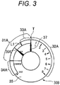
- the first display portion 36 is not limited to the image of the belt-like figure, and may be, for example, as illustrated in Fig. 3 , a needle similar to a second display portion 37 described later.
- FIG. 3 is an explanatory view showing another example of the embodiment of the display device for a hybrid vehicle according to the present invention.
- Configuration elements of a display device 30B in Fig. 3 are same as those of the display device 30A in Figs. 2A to 2C without a first display portion 36Ain Fig. 3 .
- Fig. 3 if the configuration elements are same as the configuration elements in Figs. 2A to 2C , same reference numbers of the configuration elements of Figs. 2A to 2C are added to the configuration elements in Fig. 3 and their explanations are omitted.
- the first display portion 36A is a needle pointing the value corresponding to the traveling output (first output) in the first mode in the first area 31A (between the positions of 9 o'clock and 12 o'clock). Specifically, the angle (an rotation angle from the position of 9 o'clock) of the needle of the first display portion 36A changes according to the traveling output (first output) in the first mode, and the value corresponding to the traveling output (first output) in the first mode is indicated by the pointing direction (a clockwise rotation angle from the position of 9 o'clock as the starting point).
- first display portion 36A and a second display portion 37 described hereinafter are needles respectively, that means, the first display portion and the second display portion are shown in same display forms, when both of the first display portion and the second display portion respectively change (move) in the second mode, the same display forms of the first display portion and the second display portion move together. Therefore, the visibility of the first display portion and the second display portion are improved and the designability and appearance of them are increased.
- an output parameter such as the battery output of the battery 13 may be used.
- the third area 33A is provided in the first area 31A.
- the third area 33A is provided in a position adjacent to the second area (32A) in the first area (31A).
- a sectioning line (boundary) L1 representative of the starting point of the third area 33A is provided in the first area 31A.
- the sectioning line L1 is a display indicating the position of the limit of the state where traveling using the motor 11 with the engine 12 being stopped takes precedence in the first mode (the value corresponding to the traveling output).
- the state where traveling using the motor 11 with the engine 12 being stopped takes precedence is a state where none of a plurality of conditions to start the engine 12 holds.
- the state where there is a possibility (the possibility is high) that the engine 12 starts is a state where at least one of the conditions to start the engine 12 holds.
- the sectioning line L1 indicates the boundary between these states, that is, the limit area of the state where traveling using the motor 11 with the engine 12 being stopped takes precedence.
- the engine 12 starts at a position in the counterclockwise direction with reference to the sectioning line L1 (in the first area 31A).
- the third area 33A included in the first area 31A is an engine start imminent area indicating the traveling output when at least one of the conditions to start the engine 12 holds to increase the possibility that the engine 12 starts, that is, when there is a possibility (the possibility is high) that shift is made from the first mode to the second mode.
- the third area 33A is disposed in a fan-like or arc-like shape between the position of the sectioning line L1 and the position of 0 degrees (0 o'clock) (a position adjacent to the second area 32A) in the first area 31A.
- the first display portion 36 changes within the range of the area except the third area 33A in the first area 31A, whereas when there is a possibility (the possibility is high) that the engine 12 starts, that is, immediately before the start of the engine 12, the first display portion 36 changes within the range of the third area 33A in the first area 31A.
- the driver can be notified that the engine 12 is in a state of readily starting. Therefore, it becomes easy for the driver to recognize the traveling state of the hybrid vehicle 10 and the operation state of the motor 11, grasp the traveling output and realize intended driving.
- the first area 31A may include an area indicating the output of the motor 11 (motor output) at the time of traveling with the engine 12 being actuated, that is, in the second mode. At this time, the sectioning line L1 is non-displayed, and the first display portion 36 indicates the value corresponding to the motor output (second output) in the first area 31A (between the positions of 9 o'clock and 12 o'clock).
- the length (the length from the position of 9 o'clock) of the belt-like figure of the first display portion 36 changes according to the motor output (second output), and the value corresponding to the motor output (second output) is indicated by the length of the belt-like figure (the position of the ending point [end portion] with the position of 9 o'clock as the starting point).
- the motor output (second output) is an output by the actuation of the motor 11, and as this motor output (second output), output parameters such as the rotation speed of the motor 11, the motive power (power) by the actuation of the motor 11 and the battery output of the battery 13 (the assist electric power of the motor 11) may be used.
- the change of the display in the first area 31A becomes conspicuous when shift is made from the first mode to the second mode, so that the driver can easily judge the traveling state of the hybrid vehicle 10, in particular, that the hybrid vehicle 10 is traveling in the second mode.
- a structure may be adopted in which the traveling output (first output) in the first mode and the motor output (second output) in the second mode are selectable by the driver.
- a selection switch (not shown) is provided on the display device 30A, and by operating this selection switch, one output parameter is selected from among the above-mentioned output parameters as each of the traveling output (first output) in the first mode and the motor output (second output) in the second mode.
- the first display portion 36 is made to change according to the same output parameter in the first mode and in the second mode, control can be simplified.
- the driver can obtain information on the assist output of the motor 11 as appropriate information conforming to the traveling state of the hybrid vehicle 10, more specifically, can check the excess outputs of the motor 11 and the battery 13.
- the second area 32A is an area indicating the traveling output (third output) at the time of traveling with the engine 12 being actuated, that is, in the second mode, and is disposed in a fan-like or arc-like shape between the positions of 0 degrees and approximately 135 degrees on the outer periphery on the instrument board 35.
- a second display portion 37 that is separately provided from the first display portion 36 and that changes according to the traveling output (third output) in the second mode is displayed.
- the second display portion 37 is a needle pointing the value corresponding to the engine output in the second area 32A (between the positions of 0 degrees and approximately 135 degrees). Specifically, the pointing direction (the rotation angle from the direction of 0 o'clock [0 degrees] with the substantial center of the instrument board 35 as the base point) of the second display portion 37 changes according to the traveling output (third output) in the second mode, and the value corresponding to the traveling output (third output) in the second mode is pointed by the pointing direction (direction with the substantial center of the instrument board 35 as the base point).
- the traveling in the second mode can be more clearly notified to the driver by a dynamic movement of the needle.
- output parameters such as the rotation speed of the engine 12 and the motive power (power) by the actuation of the engine 12 may be used.
- a structure may be adopted in which the traveling output (third output) in the second mode is selectable by the driver.
- a selection switch (not shown) is provided on the display device 30A, and by operating this selection switch, one output parameter is selected from among the above-mentioned output parameters as the traveling output (third output) in the second mode.
- the driver can easily grasp such actuation of the engine 11 (for a purpose other than traveling).
- the fourth area 34A is an area indicating the charging output of the battery 13 by regenerative energy, and is disposed in a fan-like or arc-like shape between the positions of approximately 225 degrees and 270 degrees on the outer periphery on the instrument board 35.
- a regenerative energy display portion (not shown) that changes according to the power generation output of the motor 11 by regenerative energy is displayed.
- the regenerative energy display portion is an image of a belt-like figure indicating the value corresponding to the power generation output of the motor 11 by regenerative energy in the fourth area 34A (between the positions of approximately 225 degrees and 270 degrees).
- the length (the length from the position of 270 degrees) of the belt-like figure of the regenerative energy display portion (not shown) changes according to the power generation output of the motor 11 by regenerative energy
- the value corresponding to the power generation output of the motor 11 by regenerative energy is indicated by the length of the belt-like figure (the position of the ending point [end portion] with the position of 270 degrees as the starting point).
- the first display portion 36 and the regenerative energy display portion are images of belt-like figures
- the second display portion 37 is a needle of an analog meter.
- the first display portion 36 and the regenerative energy display portion may be needles
- the second display portion 37 may be an image of a belt-like figure.
- the first display portion 36 and the second display portion 37 be shown in display forms different from each other.
- the different display forms may be any that enable the driver to clearly distinguish the display portions from each other, and are not limited to the image of the belt-like figure and the needle described above.
- first area 31A (including the third area 33A), second area 32A and fourth area 34A are disposed in fan-like or arc-like shapes in predetermined ranges, respectively, are independently disposed in similar fan-like or arc-like shapes in the predetermined ranges, and are also disposed in a fan-like or arc-like shape as a whole.
- the first area 31A (including the third area 33A) and the second area 32A are provided so as to range with each other in an arc-shape with the position of 12 o'clock as the boundary.
- FIGS. 1 and 2A to 2C The operation of the display device according to the first embodiment of the present invention will be described with reference to FIGS. 1 and 2A to 2C .
- the hybrid vehicle 10 starts to travel in the first mode.
- the first display portion 36 and the sectioning line L1 are displayed in the first area 31A, and the first display portion 36 changes within the range of the first area 31A according to the traveling output (first output) in the first mode (see FIGS. 2A and 2B ).
- the engine 12 is not started, and the second display portion 37 is not swung in the second area 32A (indicates the scale "0").
- the first display portion 36 and the sectioning line L1 are displayed by a predetermined output parameter or an arbitrary output parameter (for example, the engine start imminence) selected by a non-illustrated selection switch as the travelling output (first output) in the first mode.
- a predetermined output parameter or an arbitrary output parameter for example, the engine start imminence
- the driver can easily recognize that the hybrid vehicle 10 is traveling in the first mode (the traveling state of the hybrid vehicle 10) because the second display portion 37 is not swung in the second area 32A (indicates the scale "0") on the instrument board 35 of the display device 30A.
- sectioning line L1 (the third area 33A) being displayed on the instrument board 35 of the display device 30A also enables the driver to easily recognize that the hybrid vehicle 10 is traveling in the first mode (the traveling state of the hybrid vehicle 10).
- the traveling output in the first mode is a traveling output (first output) not exceeding the sectioning line L1, that is, a traveling output with no possibility that the engine 12 starts
- the first display portion 36 changes within the range of the area except the third area 33A in the first area 31A according to the traveling output (first output) in the first mode.
- the driver easily recognizes that traveling in the first mode is possible, and can continue traveling in the first mode with security.
- the traveling output (first output) in the first mode becomes a traveling output exceeding the sectioning line L1, that is, a traveling output with the possibility that the engine 12 starts
- the first display portion 36 changes within the range of the third area 33 A in the first area 31A according to the traveling output in the first mode until the engine 12 starts (see FIG. 2B ).
- the hybrid vehicle 10 can be operated with the positional relationship between the first display portion 36 and the sectioning line L1 (the third area 33A in the first area 31A) being grasped, for example, when not wanting to start the engine 12, the driver can perform an operation to return the first display portion 36 into the range of the area except the third area 33A in the first area 31A by operating the accelerator position or the like.
- the traveling output (first output) in the first mode exceeds, for example, the maximum output of the battery 13, the engine 12 starts, and the hybrid vehicle 10 starts to travel in the second mode.
- the second display portion 37 swings (is displayed/is moved) from the scale "0" in the second area 32A, and the second display portion 37 changes within the range of the second area 32A according to the traveling output (third output) in the second mode (see FIG. 2C ).
- the second display portion 37 is displayed by a predetermined output parameter or an arbitrary output parameter selected by a non-illustrated selection switch (for example, the rotation speed of the engine 12) as the traveling output (third output) in the second mode
- the first display portion 36 is displayed by a predetermined output parameter or an arbitrary output parameter selected by a non-illustrated selection switch (for example, the rotation speed of the motor 11) as the motor output (second output) in the second mode.
- the sectioning line L1 is non-displayed.
- the driver can easily recognize that the hybrid vehicle 10 shifts from the first mode to the second mode by a dynamic movement of the second display portion 37 at the time of the start of traveling in the second mode on the instrument board 35 of the display device 30A, and can easily recognize that the hybrid vehicle 10 is traveling in the second mode (the traveling state of the hybrid vehicle 10) because the second display portion 37 is swung in the second area 32A (indicates a scale other than "0").
- the driver can easily recognize that the hybrid vehicle 10 is traveling in the second mode (the traveling state of the hybrid vehicle 10).
- the display device 30A since the first display portion 36 that changes according to the traveling output (first output) in the first mode and the motor output (second output) in the second mode is displayed in the first area 31A including the third area 33A and the second display portion 37 that changes according to the traveling output (third output) in the second mode is displayed in the second area 32A, the driver can easily judge the traveling state of the hybrid vehicle 10 by grasping which of the first display portion 36 and the second display portion 37 is changed. Therefore, it becomes easy for the driver to realize intended driving by correctly grasping the traveling state of the hybrid vehicle 10.
Abstract
Description
- The present invention relates to a display device for a hybrid vehicle having a motor and an engine.
- A hybrid vehicle has a motor and an engine as driving sources for traveling, and as traveling modes thereof, has an EV (electric vehicle) mode in which the driving wheels are driven only by the motor and an HV (hybrid vehicle) mode in which the driving wheels are driven by the motor and the engine.
- The hybrid vehicle travels in the EV mode when starting, and thereafter, according to the state of the vehicle, starts the engine and travels in the HV mode. The display device of such hybrid vehicle indicates to the driver whether the vehicle is currently traveling in the EV mode or in the HV mode (for example, see
JP-B-4155321 - For example,
JP-B-4155321 - However, since the above-mentioned dividing line changes according to the state of the vehicle and sometimes moves irrespective of the driver's driving operation, not only it is difficult for the driver to judge the traveling state of the hybrid vehicle but also start of the engine (shift from the EV mode to the HV mode) at an unexpected timing and the like can occur.
- The present invention is made in view of the above-mentioned problem, and an object thereof is to make the traveling state of the hybrid vehicle easy-to-understand.
- According to the present invention, there is provided the display device as defined in the appended claims.
- There is also disclosed a display device for a hybrid vehicle of a first aspect which displays at least one of outputs related to traveling of a hybrid vehicle, the display device including:
- a first area configured to indicate a first output in a first mode in which traveling is performed with an electric motor while an internal combustion engine is stopped and to indicate a second output in a second mode in which traveling is performed with the internal combustion engine and the electric motor both being actuated;
- a second area provided side by side with the first area and configured to indicate a third output in the second mode; and
- a third area provided in a position adjacent to the second area, included in the first area, and configured to indicate a range of the first output where a possibility that the internal combustion engine starts is high,
- wherein the first area has a first display portion that changes according to the first output in the first mode and the second output in the second mode; and
- wherein the second area has a second display portion that changes according to the third output in the second mode.
- In a display device of a second aspect according to the first aspect,
the first display portion and the second display portion are provided respectively; and
in the first mode, the second display portion is fixed at a starting point of the second area. - For example, a starting point of the second area is positioned on a boundary line between the first area and the second area. In other words, the starting point of the second area is positioned on 12 o'clock in the display device (12 o'clock is equal to the position of 0 degree).
- In a display device of a third aspect according to the first aspect or the second aspect,
a sectioning line indicating a starting point of the third area is provided in the first area; and
the sectioning line is non-displayed in the second mode. - In a display device of a fourth aspect according to the third aspect,
the sectioning line becomes non-displayed in response to a shift from the first mode to the second mode. - In a display device of a fifth aspect according to any one of the first aspect to the fourth aspect,
the first mode and the second mode are shown in same display forms. - In a display device of a sixth aspect according to any one of the first aspect to the fourth aspect,
the first display portion and the second display portion are shown in different display forms. - In a display device of a seventh aspect according to any one of the first aspect to the sixth aspect,
the first display portion is an image of a belt-like figure. - In a display device of an eighth aspect according to any one of the first aspect to the sixth aspect,
the second display portion is a needle. - In a display device of a ninth aspect according to any one of the first aspect to the eighth aspect,
the first output and the second output indicate the same output parameter. - In a display device of a tenth aspect according to any one of the first aspect to the ninth aspect,
the second output indicates an output of the electric motor or an output of a battery connected to the electric motor; and
the first display portion changes according to the output of the electric motor or the output of the battery connected to the electric motor in the second mode. - In a display device of an eleventh aspect according to any one of the first aspect to the tenth aspect,
a display area formed of the first area and the second area is shaped in a circle; and
the first area and the second area are provided so as to range with each other in a fan-like or arc-like shape with an uppermost position of the display area as a boundary. - In a display device of a twelfth aspect according to any one of the first aspect to the eleventh aspect,
the second area indicates an engine speed of the internal combustion engine; and
the second display portion changes according to the engine speed of the internal combustion engine. - In a display device of a thirteenth aspect according to any one of the fifth aspect, the ninth aspect, the tenth aspect, the eleventh aspect and the twelfth aspect,
the first display portion and the second display portion are needles. - In a display device according to a ninth aspect which display device solves the above-mentioned problem, in the display device according to any one of the first to eighth aspects, the second area indicates an engine speed of the internal combustion engine, and the second display portion changes according to the engine speed of the internal combustion engine.
- According to the display device according to the first aspect, since the first display portion that changes according to the first output in the first mode or the second output in the second mode is displayed in the first area including the third area and the second display portion that changes according to the third output in the second mode is displayed in the second area, the driver can easily judge the traveling state of the hybrid vehicle by grasping which of the first display portion and the second display portion is changed.
- According to the display device according to the second aspect, since the first display portion and the second display portion are provided respectively and in the first mode, the second display portion is fixed at a starting point of the second area, the driver can easily grasp a movement or change of the first display portion and also can easily judge the traveling state of the hybrid vehicle.
- According to the display device according to the third and fourth aspects, by making the sectioning line (the third area) in the second mode non-displayed, the change of the display in the first area in the second mode becomes conspicuous, so that the driver can easily judge the traveling state of the hybrid vehicle, in particular, that the hybrid vehicle is traveling in the second mode. Moreover, by displaying the sectioning line (the third area) in the first traveling mode, the driver can be notified that the engine is in a state of readily starting.
- According to the display device according to the fifth aspect and the thirteenth aspect, since the first mode and the second mode are shown in same display forms, when both of the first mode and the second mode in the second mode are operated, the same display forms are moved together, the visibility of the first display portion and the second display portion are improved and the designability and appearance of them are increased.
- According to the display device according to the sixth aspect, since the first display portion and the second display portion are shown in different display forms, the driver can clearly distinguish the display portions from each other, so that the traveling state of the hybrid vehicle can be more easily judged.
- According to the display device according to the seventh aspect, since the first display portion is an image of a belt-like figure, when the hybrid vehicle travels without the engine being started in the first mode, the driver can be more clearly notified of that state, so that viewability is improved.
- According to the display device according to the eighth aspect, since the second display portion is a needle, when the traveling in the second mode is started, the traveling in the second mode can be more clearly notified to the driver by a dynamic movement of the needle.
- According to the display device according to the ninth aspect, by displaying the first display portion with the same output parameter in the first mode and in the second mode, control can be simplified.
- According to the display device according to the tenth aspect, by displaying the first display portion with the output of the electric motor or the output of the battery in the second mode, the driver can obtain information on the assist output of the electric motor as appropriate information conforming to the traveling state of the hybrid vehicle, more specifically, can check the excess outputs of the electric motor and the battery.
- According to the display device according to the eleventh aspect, since the first area and the second area are disposed so as to range with each other with the uppermost portion of the display area as the boundary, it becomes easy for the driver to intuitively grasp the display information of the display device (the operation state of the hybrid vehicle).
- According to the display device according to the twelfth aspect, by displaying the second display portion with the engine speed of the internal combustion engine, for example, even when the engine is actuated by the warm air of the catalyst or the like, the driver can easily grasp such actuation of the engine (for a purpose other than traveling).
-
-
FIG. 1 is a block diagram explaining a hybrid vehicle. -
FIG. 2A is an explanatory view showing an example of an embodiment of a display device for a hybrid vehicle according to the present invention. -
FIG. 2B is an explanatory view showing an example of the embodiment of the display device for a hybrid vehicle according to the present invention. -
FIG. 2C is an explanatory view showing an example of the embodiment of the display device for a hybrid vehicle according to the present invention. -
FIG. 3 is an explanatory view showing another example of the embodiment of the display device for a hybrid vehicle according to the present invention. - Hereinafter, an embodiment of the display device according to the present invention will be described in detail with reference to the attached drawings. Needless to say, the present invention is not limited to the following embodiment and may be variously modified without departing from the gist of the invention.
- The structure of a display device according to a first embodiment of the present invention will be described with reference to
FIG. 1 andFIGS. 2A to 2C . - As shown in
FIG. 1 , ahybrid vehicle 10 has a motor 11 (electric motor) and an engine 12 (internal combustion engine) as driving sources for traveling. Themotor 11 may have a structure of driving the front wheels or the rear wheels. Also a structure may be adopted that the front wheels and the rear wheels are driven by a plurality ofmotors 11, respectively. Moreover, theengine 12 may also have the structure of driving the front wheels or the rear wheels or may have the structure of driving both of the front wheels and the rear wheels. Moreover, thehybrid vehicle 10 may have a generator (not shown) that is driven by theengine 12 to generate power. - As traveling modes, the
hybrid vehicle 10 has a first mode (electric motor output mode) in which traveling using themotor 11 with theengine 12 being stopped (driving of the driving wheels) takes precedence (traveling by themotor 11 takes precedence over traveling by the engine 12) and a second mode (internal combustion engine output mode) in which theengine 12 is actuated and thehybrid vehicle 10 travels (the driving wheels are driven) by using, for example, themotor 11 and theengine 12. - Moreover, the
hybrid vehicle 10 has an ECU (Electronics Control Unit) 20 as the control portion. TheECU 20 has a CPU (Central Processing Unit), a RAM (Random Access Memory), a ROM (Read Only Memory), an input/output circuit and the like, is electrically connected to themotor 11 and theengine 12, and is electrically connected also to abattery 13 that supplies power to themotor 11, avehicle speed sensor 14 that detects the vehicle speed and anaccelerator position sensor 15 that detects the accelerator position. - Therefore, to the
ECU 20, a signal value from the motor 11 (the motor rotation speed, etc.) and a signal value from the engine 12 (ON/OFF, the engine rotation speed, etc.) are inputted, and further, a signal value from the battery 13 (SOC [state of charge], the battery output, etc.), signal values of thevehicle speed sensor 14 and theaccelerator position sensor 15 and the like are also inputted. - The
hybrid vehicle 10 further has adisplay device 30A that displays at least one of outputs related to the traveling of the hybrid vehicle 10 (traveling output), and thedisplay device 30A is electrically connected to theECU 20. The traveling output of thehybrid vehicle 10 is obtained by arithmetic processing being performed at theECU 20 based on the above-mentioned signal value, and this arithmetically processed value (traveling output) is inputted to thedisplay device 30A. - As shown in
FIGS. 2A to 2C , thedisplay device 30A has acircular instrument board 35 where afirst area 31A (including athird area 33A), asecond area 32A and afourth area 34A are disposed. In the following description, as the expression of the direction on theinstrument board 35, one or both of the following are used: the time of a clock with the uppermost position of theinstrument board 35 as the position of 0 o'clock (=12 o'clock); and an angle when the uppermost position T of theinstrument board 35 is the position of 0 degrees (=360 degrees). - The
first area 31A is an area indicating the traveling output (first output) at the time of traveling using themotor 11 while theengine 12 is stopped, that is, in the first mode. Thefirst area 31A is disposed in a fan-like or arc-like shape between the positions of approximately 270 degrees and 360 degrees (between the positions of approximately 9 o'clock and 12 O'clock in a hypothetical dial plate) on the outer periphery on theinstrument board 35. In thefirst area 31A, afirst display portion 36 that changes according to the traveling output in the first mode is displayed. - The
first display portion 36 is an image of a belt-like figure indicating the value corresponding to the traveling output (first output) in the first mode in thefirst area 31A (between the positions of 9 o'clock and 12 o'clock). Specifically, the length (the length from the position of 9 o'clock) of the belt-like figure of thefirst display portion 36 changes according to the traveling output (first output) in the first mode, and the value corresponding to the traveling output (first output) in the first mode is indicated by the length of the belt-like figure (the position of the ending point [end portion] with the position of 9 o'clock as the starting point). - By the
first display portion 36 being the image of the belt-like figure as described above, when thehybrid vehicle 10 travels without theengine 12 being started in the first mode, the driver can be more clearly notified of the traveling state of the vehicle and the start/stop condition of the engine, so that viewability is improved. Thefirst display portion 36 is not limited to the image of the belt-like figure, and may be, for example, as illustrated inFig. 3 , a needle similar to asecond display portion 37 described later. -
FIG. 3 is an explanatory view showing another example of the embodiment of the display device for a hybrid vehicle according to the present invention. Configuration elements of adisplay device 30B inFig. 3 are same as those of thedisplay device 30A inFigs. 2A to 2C without a first display portion 36AinFig. 3 . InFig. 3 , if the configuration elements are same as the configuration elements inFigs. 2A to 2C , same reference numbers of the configuration elements ofFigs. 2A to 2C are added to the configuration elements inFig. 3 and their explanations are omitted. - The first display portion 36A is a needle pointing the value corresponding to the traveling output (first output) in the first mode in the
first area 31A (between the positions of 9 o'clock and 12 o'clock). Specifically, the angle (an rotation angle from the position of 9 o'clock) of the needle of the first display portion 36A changes according to the traveling output (first output) in the first mode, and the value corresponding to the traveling output (first output) in the first mode is indicated by the pointing direction (a clockwise rotation angle from the position of 9 o'clock as the starting point). - Since the first display portion 36A and a
second display portion 37 described hereinafter are needles respectively, that means, the first display portion and the second display portion are shown in same display forms, when both of the first display portion and the second display portion respectively change (move) in the second mode, the same display forms of the first display portion and the second display portion move together. Therefore, the visibility of the first display portion and the second display portion are improved and the designability and appearance of them are increased. - As the traveling output (first output) in the first mode, for example, an output parameter such as the battery output of the
battery 13 may be used. - Moreover, in the
first area 31A, thethird area 33A is provided. Thethird area 33A is provided in a position adjacent to the second area (32A) in the first area (31A). In thefirst area 31A, a sectioning line (boundary) L1 representative of the starting point of thethird area 33A is provided. The sectioning line L1 is a display indicating the position of the limit of the state where traveling using themotor 11 with theengine 12 being stopped takes precedence in the first mode (the value corresponding to the traveling output). - The state where traveling using the
motor 11 with theengine 12 being stopped takes precedence is a state where none of a plurality of conditions to start theengine 12 holds. On the other hand, the state where there is a possibility (the possibility is high) that theengine 12 starts is a state where at least one of the conditions to start theengine 12 holds. The sectioning line L1 indicates the boundary between these states, that is, the limit area of the state where traveling using themotor 11 with theengine 12 being stopped takes precedence. Depending on the condition, there are cases where theengine 12 starts at a position in the counterclockwise direction with reference to the sectioning line L1 (in thefirst area 31A). - That is, the
third area 33A included in thefirst area 31A is an engine start imminent area indicating the traveling output when at least one of the conditions to start theengine 12 holds to increase the possibility that theengine 12 starts, that is, when there is a possibility (the possibility is high) that shift is made from the first mode to the second mode. Moreover, thethird area 33A is disposed in a fan-like or arc-like shape between the position of the sectioning line L1 and the position of 0 degrees (0 o'clock) (a position adjacent to thesecond area 32A) in thefirst area 31A. - Therefore, in the first mode, when there is no possibility (the possibility is low) that the
engine 12 starts, thefirst display portion 36 changes within the range of the area except thethird area 33A in thefirst area 31A, whereas when there is a possibility (the possibility is high) that theengine 12 starts, that is, immediately before the start of theengine 12, thefirst display portion 36 changes within the range of thethird area 33A in thefirst area 31A. - Since the possibility of the
engine 12 starting can be indicated by thefirst display portion 36 by providing such athird area 33A in thefirst area 31A, the driver can be notified that theengine 12 is in a state of readily starting. Therefore, it becomes easy for the driver to recognize the traveling state of thehybrid vehicle 10 and the operation state of themotor 11, grasp the traveling output and realize intended driving. - Moreover, the
first area 31A may include an area indicating the output of the motor 11 (motor output) at the time of traveling with theengine 12 being actuated, that is, in the second mode. At this time, the sectioning line L1 is non-displayed, and thefirst display portion 36 indicates the value corresponding to the motor output (second output) in thefirst area 31A (between the positions of 9 o'clock and 12 o'clock). Specifically, the length (the length from the position of 9 o'clock) of the belt-like figure of thefirst display portion 36 changes according to the motor output (second output), and the value corresponding to the motor output (second output) is indicated by the length of the belt-like figure (the position of the ending point [end portion] with the position of 9 o'clock as the starting point). - The motor output (second output) is an output by the actuation of the
motor 11, and as this motor output (second output), output parameters such as the rotation speed of themotor 11, the motive power (power) by the actuation of themotor 11 and the battery output of the battery 13 (the assist electric power of the motor 11) may be used. - By making the sectioning line L1 in the second mode non-displayed as described above, the change of the display in the
first area 31A becomes conspicuous when shift is made from the first mode to the second mode, so that the driver can easily judge the traveling state of thehybrid vehicle 10, in particular, that thehybrid vehicle 10 is traveling in the second mode. - A structure may be adopted in which the traveling output (first output) in the first mode and the motor output (second output) in the second mode are selectable by the driver. For example, a selection switch (not shown) is provided on the
display device 30A, and by operating this selection switch, one output parameter is selected from among the above-mentioned output parameters as each of the traveling output (first output) in the first mode and the motor output (second output) in the second mode. In a case where thefirst display portion 36 is made to change according to the same output parameter in the first mode and in the second mode, control can be simplified. - Moreover, in a case where the
first area 31A indicates the output of themotor 11 or the output of thebattery 13 in the second mode and thefirst display portion 36 changes according to the output of themotor 11 or the output of thebattery 13 in the second mode, the driver can obtain information on the assist output of themotor 11 as appropriate information conforming to the traveling state of thehybrid vehicle 10, more specifically, can check the excess outputs of themotor 11 and thebattery 13. - The
second area 32A is an area indicating the traveling output (third output) at the time of traveling with theengine 12 being actuated, that is, in the second mode, and is disposed in a fan-like or arc-like shape between the positions of 0 degrees and approximately 135 degrees on the outer periphery on theinstrument board 35. In thesecond area 32A, asecond display portion 37 that is separately provided from thefirst display portion 36 and that changes according to the traveling output (third output) in the second mode is displayed. - The
second display portion 37 is a needle pointing the value corresponding to the engine output in thesecond area 32A (between the positions of 0 degrees and approximately 135 degrees). Specifically, the pointing direction (the rotation angle from the direction of 0 o'clock [0 degrees] with the substantial center of theinstrument board 35 as the base point) of thesecond display portion 37 changes according to the traveling output (third output) in the second mode, and the value corresponding to the traveling output (third output) in the second mode is pointed by the pointing direction (direction with the substantial center of theinstrument board 35 as the base point). - By making the
second display portion 37 the needle as described above, when the traveling in the second mode is started, the traveling in the second mode can be more clearly notified to the driver by a dynamic movement of the needle. - As the traveling output (third output) in the second mode, output parameters such as the rotation speed of the
engine 12 and the motive power (power) by the actuation of theengine 12 may be used. - A structure may be adopted in which the traveling output (third output) in the second mode is selectable by the driver. For example, a selection switch (not shown) is provided on the
display device 30A, and by operating this selection switch, one output parameter is selected from among the above-mentioned output parameters as the traveling output (third output) in the second mode. - In a case where the
second display portion 37 is displayed by the rotation speed of theengine 11, for example, even when theengine 11 is actuated by the warm air of the catalyst or the like, the driver can easily grasp such actuation of the engine 11 (for a purpose other than traveling). - The
fourth area 34A is an area indicating the charging output of thebattery 13 by regenerative energy, and is disposed in a fan-like or arc-like shape between the positions of approximately 225 degrees and 270 degrees on the outer periphery on theinstrument board 35. In thefourth area 34A, a regenerative energy display portion (not shown) that changes according to the power generation output of themotor 11 by regenerative energy is displayed. - The regenerative energy display portion (not shown) is an image of a belt-like figure indicating the value corresponding to the power generation output of the
motor 11 by regenerative energy in thefourth area 34A (between the positions of approximately 225 degrees and 270 degrees). Specifically, the length (the length from the position of 270 degrees) of the belt-like figure of the regenerative energy display portion (not shown) changes according to the power generation output of themotor 11 by regenerative energy, and the value corresponding to the power generation output of themotor 11 by regenerative energy is indicated by the length of the belt-like figure (the position of the ending point [end portion] with the position of 270 degrees as the starting point). - On the above-described
instrument board 35, in thefirst area 31A (including thethird area 33A) and thefourth area 34A, no scale numerals are provided, and in thesecond area 32A, scale numerals are provided. Needless to say, scale numerals may be provided in thefirst area 31A (including thethird area 33A) and thefourth area 34A, and scale numerals may be not provided in thesecond area 32A. - Moreover, on the above-described
instrument board 35, thefirst display portion 36 and the regenerative energy display portion (not shown) are images of belt-like figures, and thesecond display portion 37 is a needle of an analog meter. Needless to say, thefirst display portion 36 and the regenerative energy display portion (not shown) may be needles, and thesecond display portion 37 may be an image of a belt-like figure. At this time, it is preferable that thefirst display portion 36 and thesecond display portion 37 be shown in display forms different from each other. The different display forms may be any that enable the driver to clearly distinguish the display portions from each other, and are not limited to the image of the belt-like figure and the needle described above. - Moreover, the above-described
first area 31A (including thethird area 33A),second area 32A andfourth area 34A are disposed in fan-like or arc-like shapes in predetermined ranges, respectively, are independently disposed in similar fan-like or arc-like shapes in the predetermined ranges, and are also disposed in a fan-like or arc-like shape as a whole. Thefirst area 31A (including thethird area 33A) and thesecond area 32A are provided so as to range with each other in an arc-shape with the position of 12 o'clock as the boundary. - By making circular the display area formed of the
first area 31A and thesecond area 32A and providing thefirst area 31A and thesecond area 32A so as to range with each other in a fan-like or arc-like shape with the uppermost position T of the display area (the instrument board 35) as the boundary as described above, it becomes easy for the driver to intuitively grasp the display information of thedisplay device 30A (the operation state of the hybrid vehicle 10). - The operation of the display device according to the first embodiment of the present invention will be described with reference to
FIGS. 1 and2A to 2C . - When the driver starts the
hybrid vehicle 10, thehybrid vehicle 10 starts to travel in the first mode. - At this time, on the
instrument board 35 of thedisplay device 30A, thefirst display portion 36 and the sectioning line L1 are displayed in thefirst area 31A, and thefirst display portion 36 changes within the range of thefirst area 31A according to the traveling output (first output) in the first mode (seeFIGS. 2A and 2B ). In the first mode, theengine 12 is not started, and thesecond display portion 37 is not swung in thesecond area 32A (indicates the scale "0"). - The
first display portion 36 and the sectioning line L1 are displayed by a predetermined output parameter or an arbitrary output parameter (for example, the engine start imminence) selected by a non-illustrated selection switch as the travelling output (first output) in the first mode. - Therefore, the driver can easily recognize that the
hybrid vehicle 10 is traveling in the first mode (the traveling state of the hybrid vehicle 10) because thesecond display portion 37 is not swung in thesecond area 32A (indicates the scale "0") on theinstrument board 35 of thedisplay device 30A. - Moreover, the sectioning line L1 (the
third area 33A) being displayed on theinstrument board 35 of thedisplay device 30A also enables the driver to easily recognize that thehybrid vehicle 10 is traveling in the first mode (the traveling state of the hybrid vehicle 10). - While the traveling output in the first mode is a traveling output (first output) not exceeding the sectioning line L1, that is, a traveling output with no possibility that the
engine 12 starts, thefirst display portion 36 changes within the range of the area except thethird area 33A in thefirst area 31A according to the traveling output (first output) in the first mode. - Therefore, from the display of the
first display portion 36 and the sectioning line L1 in thefirst area 31A (thefirst display portion 36 changing in the range of the area except thethird area 33 A in thefirst area 31A), the driver easily recognizes that traveling in the first mode is possible, and can continue traveling in the first mode with security. - On the other hand, when the traveling output (first output) in the first mode becomes a traveling output exceeding the sectioning line L1, that is, a traveling output with the possibility that the
engine 12 starts, thefirst display portion 36 changes within the range of thethird area 33 A in thefirst area 31A according to the traveling output in the first mode until theengine 12 starts (seeFIG. 2B ). - Therefore, since the
hybrid vehicle 10 can be operated with the positional relationship between thefirst display portion 36 and the sectioning line L1 (thethird area 33A in thefirst area 31A) being grasped, for example, when not wanting to start theengine 12, the driver can perform an operation to return thefirst display portion 36 into the range of the area except thethird area 33A in thefirst area 31A by operating the accelerator position or the like. - Then, when the traveling output (first output) in the first mode exceeds, for example, the maximum output of the
battery 13, theengine 12 starts, and thehybrid vehicle 10 starts to travel in the second mode. - At this time, on the
instrument board 35 of thedisplay device 30A, thesecond display portion 37 swings (is displayed/is moved) from the scale "0" in thesecond area 32A, and thesecond display portion 37 changes within the range of thesecond area 32A according to the traveling output (third output) in the second mode (seeFIG. 2C ). - The
second display portion 37 is displayed by a predetermined output parameter or an arbitrary output parameter selected by a non-illustrated selection switch (for example, the rotation speed of the engine 12) as the traveling output (third output) in the second mode, and thefirst display portion 36 is displayed by a predetermined output parameter or an arbitrary output parameter selected by a non-illustrated selection switch (for example, the rotation speed of the motor 11) as the motor output (second output) in the second mode. The sectioning line L1 is non-displayed. - Therefore, the driver can easily recognize that the
hybrid vehicle 10 shifts from the first mode to the second mode by a dynamic movement of thesecond display portion 37 at the time of the start of traveling in the second mode on theinstrument board 35 of thedisplay device 30A, and can easily recognize that thehybrid vehicle 10 is traveling in the second mode (the traveling state of the hybrid vehicle 10) because thesecond display portion 37 is swung in thesecond area 32A (indicates a scale other than "0"). - Moreover, since the sectioning line L1 (the
third area 33A) is non-displayed on theinstrument board 35 of thedisplay device 30A, the driver can easily recognize that thehybrid vehicle 10 is traveling in the second mode (the traveling state of the hybrid vehicle 10). - As described above, according to the
display device 30A, since thefirst display portion 36 that changes according to the traveling output (first output) in the first mode and the motor output (second output) in the second mode is displayed in thefirst area 31A including thethird area 33A and thesecond display portion 37 that changes according to the traveling output (third output) in the second mode is displayed in thesecond area 32A, the driver can easily judge the traveling state of thehybrid vehicle 10 by grasping which of thefirst display portion 36 and thesecond display portion 37 is changed. Therefore, it becomes easy for the driver to realize intended driving by correctly grasping the traveling state of thehybrid vehicle 10.
Claims (12)
- A display device (30, 30A, 30B) for a hybrid vehicle (10) which displays at least one of outputs related to traveling of the hybrid vehicle, the display device comprising:a first area (31A) configured to indicate a first output in a first mode in which traveling is performed with an electric motor (11) while an internal combustion engine (12) is stopped and to indicate a second output in a second mode in which traveling is performed with the internal combustion engine (12) and the electric motor (11) both being actuated;a second area (32A) provided side by side with the first area (31A) and configured to indicate a third output in the second mode; anda third area (33A) provided in a position adjacent to the second area (32A), included in the first area (31A), and configured to indicate a range of the first output where a possibility that the internal combustion engine (12) starts is high,wherein the first area (31A) has a first display portion (36, 36A) that changes according to the first output in the first mode and the second output in the second mode; andwherein the second area (32A) has a second display portion (37) that changes according to the third output in the second mode,the display device being characterized in thatthe first display portion (36, 36A) and the second display portion (37) are provided respectively; and in thatin the first mode, the second display portion (37) is fixed at a starting point of the second area (32A).
- The display device (30, 30A, 30B) according to claim 1,
wherein a sectioning line (L1) indicating a starting point of the third area (33A) is provided in the first area (31A); and
wherein the sectioning line (L1) is non-displayed in the second mode. - The display device (30, 30A, 30B) according to claim 2,
wherein the sectioning line (L1) becomes non-displayed in response to a shift from the first mode to the second mode. - The display device (30B) according to any one of claims 1 to 3,
wherein the first display portion (36A) and the second display portion (37) are shown in same display forms. - The display device (30A) according to any one of claims 1 to 3,
wherein the first display portion (36) and the second display portion (37) are shown in different display forms. - The display device (30A) according to any one of claims 1 to 5,
wherein the first display portion (36) is an image of a belt-like figure. - The display device (30, 30A, 30B) according to any one of claims 1 to 5,
wherein the second display portion (37) is a needle. - The display device (30, 30A, 30B) according to any one of claims 1 to 7,
wherein the first output and the second output indicate the same output parameter. - The display device (30, 30A, 30B) according to any one of claims 1 to 8,
wherein the second output indicates an output of the electric motor (11) or an output of a battery (13) connected to the electric motor (11); and
wherein the first display portion (36, 36A) changes according to the output of the electric motor (11) or the output of the battery (13) connected to the electric motor (11) in the second mode. - The display device (30, 30A, 30B) according to any one of claims 1 to 9,
wherein a display area formed of the first area (31A) and the second area (32A) is shaped in a circle; and
wherein the first area (31A) and the second area (32A) are provided so as to range with each other in a fan-like or arc-like shape with an uppermost position of the display area as a boundary. - The display device (30, 30A, 30B) according to any one of claims 1 to 10,
wherein the second area (32A) indicates an engine speed of the internal combustion engine (12); and
wherein the second display portion (37) changes according to the engine speed of the internal combustion engine (12). - The display device (30B) according to any one of claims 4, 8, 9, 10 and 11,
wherein the first display portion (36A) and the second display portion (37) are needles.
Applications Claiming Priority (3)
| Application Number | Priority Date | Filing Date | Title |
|---|---|---|---|
| JP2018145583 | 2018-08-02 | ||
| JP2019128007A JP7410451B2 (en) | 2018-08-02 | 2019-07-10 | Hybrid vehicle display device |
| EP19189551.5A EP3604016B1 (en) | 2018-08-02 | 2019-08-01 | Display device for hybrid vehicle |
Related Parent Applications (2)
| Application Number | Title | Priority Date | Filing Date |
|---|---|---|---|
| EP19189551.5A Division-Into EP3604016B1 (en) | 2018-08-02 | 2019-08-01 | Display device for hybrid vehicle |
| EP19189551.5A Division EP3604016B1 (en) | 2018-08-02 | 2019-08-01 | Display device for hybrid vehicle |
Publications (2)
| Publication Number | Publication Date |
|---|---|
| EP3753774A1 true EP3753774A1 (en) | 2020-12-23 |
| EP3753774B1 EP3753774B1 (en) | 2022-09-07 |
Family
ID=67514480
Family Applications (2)
| Application Number | Title | Priority Date | Filing Date |
|---|---|---|---|
| EP20185676.2A Active EP3753774B1 (en) | 2018-08-02 | 2019-08-01 | Display device for hybrid vehicle |
| EP19189551.5A Active EP3604016B1 (en) | 2018-08-02 | 2019-08-01 | Display device for hybrid vehicle |
Family Applications After (1)
| Application Number | Title | Priority Date | Filing Date |
|---|---|---|---|
| EP19189551.5A Active EP3604016B1 (en) | 2018-08-02 | 2019-08-01 | Display device for hybrid vehicle |
Country Status (3)
| Country | Link |
|---|---|
| US (1) | US11472425B2 (en) |
| EP (2) | EP3753774B1 (en) |
| CN (1) | CN110789343B (en) |
Citations (5)
| Publication number | Priority date | Publication date | Assignee | Title |
|---|---|---|---|---|
| JP2007125921A (en) * | 2005-11-01 | 2007-05-24 | Toyota Motor Corp | Driver support system of hybrid vehicle |
| JP4155321B2 (en) | 2006-09-25 | 2008-09-24 | トヨタ自動車株式会社 | Hybrid vehicle display device, hybrid vehicle, and hybrid vehicle display method |
| US20090125173A1 (en) * | 2007-11-08 | 2009-05-14 | Toyota Jidosha Kabushiki Kaisha | Hybrid vehicle with internal combustion engine and electric motor installed |
| EP3403866A1 (en) * | 2017-05-18 | 2018-11-21 | Mitsubishi Jidosha Kogyo Kabushiki Kaisha | Display device for hybrid vehicle |
| WO2020195019A1 (en) * | 2019-03-25 | 2020-10-01 | 三菱自動車工業株式会社 | Display device |
Family Cites Families (8)
| Publication number | Priority date | Publication date | Assignee | Title |
|---|---|---|---|---|
| US7898405B2 (en) * | 2008-03-25 | 2011-03-01 | Ford Global Technologies, Llc | Vehicle information display and method |
| DE102008060265A1 (en) * | 2008-12-03 | 2010-06-10 | Dr. Ing. H.C. F. Porsche Aktiengesellschaft | Display device for a hybrid vehicle |
| DE102010020673B4 (en) * | 2010-05-15 | 2021-07-08 | Dr. Ing. H.C. F. Porsche Aktiengesellschaft | Display device for a hybrid vehicle |
| JP5704232B2 (en) * | 2011-05-10 | 2015-04-22 | トヨタ自動車株式会社 | Display device for hybrid vehicle |
| DE102011112707B4 (en) * | 2011-09-07 | 2020-11-05 | Volkswagen Aktiengesellschaft | Display device for a hybrid vehicle and method for display and hybrid vehicle |
| CN105946581B (en) * | 2016-07-06 | 2017-12-29 | 重庆长安汽车股份有限公司 | Information indicator for automobile and display methods |
| CN106042932B (en) * | 2016-07-21 | 2019-01-22 | 浙江吉利汽车研究院有限公司 | A kind of hybrid vehicle display device |
| KR20180032109A (en) * | 2016-09-21 | 2018-03-29 | 엘지전자 주식회사 | Dashboard display and vehicle comprising the same |
-
2019
- 2019-07-31 CN CN201910699323.7A patent/CN110789343B/en active Active
- 2019-08-01 EP EP20185676.2A patent/EP3753774B1/en active Active
- 2019-08-01 US US16/529,414 patent/US11472425B2/en active Active
- 2019-08-01 EP EP19189551.5A patent/EP3604016B1/en active Active
Patent Citations (5)
| Publication number | Priority date | Publication date | Assignee | Title |
|---|---|---|---|---|
| JP2007125921A (en) * | 2005-11-01 | 2007-05-24 | Toyota Motor Corp | Driver support system of hybrid vehicle |
| JP4155321B2 (en) | 2006-09-25 | 2008-09-24 | トヨタ自動車株式会社 | Hybrid vehicle display device, hybrid vehicle, and hybrid vehicle display method |
| US20090125173A1 (en) * | 2007-11-08 | 2009-05-14 | Toyota Jidosha Kabushiki Kaisha | Hybrid vehicle with internal combustion engine and electric motor installed |
| EP3403866A1 (en) * | 2017-05-18 | 2018-11-21 | Mitsubishi Jidosha Kogyo Kabushiki Kaisha | Display device for hybrid vehicle |
| WO2020195019A1 (en) * | 2019-03-25 | 2020-10-01 | 三菱自動車工業株式会社 | Display device |
Also Published As
| Publication number | Publication date |
|---|---|
| CN110789343A (en) | 2020-02-14 |
| CN110789343B (en) | 2023-01-06 |
| EP3604016B1 (en) | 2021-06-02 |
| EP3753774B1 (en) | 2022-09-07 |
| US11472425B2 (en) | 2022-10-18 |
| US20200039532A1 (en) | 2020-02-06 |
| EP3604016A1 (en) | 2020-02-05 |
Similar Documents
| Publication | Publication Date | Title |
|---|---|---|
| US10639994B2 (en) | Display device for hybrid vehicle | |
| EP3403866B1 (en) | Display device for hybrid vehicle | |
| US11320292B2 (en) | Display device for hybrid vehicle | |
| CN113631412B (en) | Display device | |
| EP2758266B1 (en) | Electric-drive tractability indicator integrated in hybrid electric vehicle tachometer | |
| EP3604016B1 (en) | Display device for hybrid vehicle | |
| JP5501075B2 (en) | Power display device for hybrid vehicles | |
| JP7410451B2 (en) | Hybrid vehicle display device | |
| JP6966723B2 (en) | Hybrid vehicle display device | |
| US11813940B2 (en) | Display device | |
| JP6908889B2 (en) | Hybrid vehicle display | |
| JP6908890B2 (en) | Hybrid vehicle display | |
| JP2020069947A (en) | Display device for hybrid vehicle |
Legal Events
| Date | Code | Title | Description |
|---|---|---|---|
| PUAI | Public reference made under article 153(3) epc to a published international application that has entered the european phase |
Free format text: ORIGINAL CODE: 0009012 |
|
| STAA | Information on the status of an ep patent application or granted ep patent |
Free format text: STATUS: THE APPLICATION HAS BEEN PUBLISHED |
|
| AC | Divisional application: reference to earlier application |
Ref document number: 3604016 Country of ref document: EP Kind code of ref document: P |
|
| AK | Designated contracting states |
Kind code of ref document: A1 Designated state(s): AL AT BE BG CH CY CZ DE DK EE ES FI FR GB GR HR HU IE IS IT LI LT LU LV MC MK MT NL NO PL PT RO RS SE SI SK SM TR |
|
| AX | Request for extension of the european patent |
Extension state: BA ME |
|
| STAA | Information on the status of an ep patent application or granted ep patent |
Free format text: STATUS: REQUEST FOR EXAMINATION WAS MADE |
|
| 17P | Request for examination filed |
Effective date: 20210113 |
|
| RBV | Designated contracting states (corrected) |
Designated state(s): AL AT BE BG CH CY CZ DE DK EE ES FI FR GB GR HR HU IE IS IT LI LT LU LV MC MK MT NL NO PL PT RO RS SE SI SK SM TR |
|
| STAA | Information on the status of an ep patent application or granted ep patent |
Free format text: STATUS: EXAMINATION IS IN PROGRESS |
|
| 17Q | First examination report despatched |
Effective date: 20210819 |
|
| RIC1 | Information provided on ipc code assigned before grant |
Ipc: B60W 50/14 20200101ALN20220331BHEP Ipc: B60K 37/02 20060101ALI20220331BHEP Ipc: B60K 35/00 20060101AFI20220331BHEP |
|
| GRAP | Despatch of communication of intention to grant a patent |
Free format text: ORIGINAL CODE: EPIDOSNIGR1 |
|
| STAA | Information on the status of an ep patent application or granted ep patent |
Free format text: STATUS: GRANT OF PATENT IS INTENDED |
|
| INTG | Intention to grant announced |
Effective date: 20220510 |
|
| RIC1 | Information provided on ipc code assigned before grant |
Ipc: B60W 50/14 20200101ALN20220429BHEP Ipc: B60K 37/02 20060101ALI20220429BHEP Ipc: B60K 35/00 20060101AFI20220429BHEP |
|
| GRAS | Grant fee paid |
Free format text: ORIGINAL CODE: EPIDOSNIGR3 |
|
| GRAA | (expected) grant |
Free format text: ORIGINAL CODE: 0009210 |
|
| STAA | Information on the status of an ep patent application or granted ep patent |
Free format text: STATUS: THE PATENT HAS BEEN GRANTED |
|
| AC | Divisional application: reference to earlier application |
Ref document number: 3604016 Country of ref document: EP Kind code of ref document: P |
|
| AK | Designated contracting states |
Kind code of ref document: B1 Designated state(s): AL AT BE BG CH CY CZ DE DK EE ES FI FR GB GR HR HU IE IS IT LI LT LU LV MC MK MT NL NO PL PT RO RS SE SI SK SM TR |
|
| REG | Reference to a national code |
Ref country code: GB Ref legal event code: FG4D |
|
| REG | Reference to a national code |
Ref country code: CH Ref legal event code: EP Ref country code: AT Ref legal event code: REF Ref document number: 1516752 Country of ref document: AT Kind code of ref document: T Effective date: 20220915 |
|
| REG | Reference to a national code |
Ref country code: IE Ref legal event code: FG4D |
|
| REG | Reference to a national code |
Ref country code: DE Ref legal event code: R096 Ref document number: 602019019453 Country of ref document: DE |
|
| REG | Reference to a national code |
Ref country code: LT Ref legal event code: MG9D |
|
| REG | Reference to a national code |
Ref country code: NL Ref legal event code: MP Effective date: 20220907 |
|
| PG25 | Lapsed in a contracting state [announced via postgrant information from national office to epo] |
Ref country code: SE Free format text: LAPSE BECAUSE OF FAILURE TO SUBMIT A TRANSLATION OF THE DESCRIPTION OR TO PAY THE FEE WITHIN THE PRESCRIBED TIME-LIMIT Effective date: 20220907 Ref country code: RS Free format text: LAPSE BECAUSE OF FAILURE TO SUBMIT A TRANSLATION OF THE DESCRIPTION OR TO PAY THE FEE WITHIN THE PRESCRIBED TIME-LIMIT Effective date: 20220907 Ref country code: NO Free format text: LAPSE BECAUSE OF FAILURE TO SUBMIT A TRANSLATION OF THE DESCRIPTION OR TO PAY THE FEE WITHIN THE PRESCRIBED TIME-LIMIT Effective date: 20221207 Ref country code: LV Free format text: LAPSE BECAUSE OF FAILURE TO SUBMIT A TRANSLATION OF THE DESCRIPTION OR TO PAY THE FEE WITHIN THE PRESCRIBED TIME-LIMIT Effective date: 20220907 Ref country code: LT Free format text: LAPSE BECAUSE OF FAILURE TO SUBMIT A TRANSLATION OF THE DESCRIPTION OR TO PAY THE FEE WITHIN THE PRESCRIBED TIME-LIMIT Effective date: 20220907 Ref country code: FI Free format text: LAPSE BECAUSE OF FAILURE TO SUBMIT A TRANSLATION OF THE DESCRIPTION OR TO PAY THE FEE WITHIN THE PRESCRIBED TIME-LIMIT Effective date: 20220907 |
|
| REG | Reference to a national code |
Ref country code: AT Ref legal event code: MK05 Ref document number: 1516752 Country of ref document: AT Kind code of ref document: T Effective date: 20220907 |
|
| PG25 | Lapsed in a contracting state [announced via postgrant information from national office to epo] |
Ref country code: HR Free format text: LAPSE BECAUSE OF FAILURE TO SUBMIT A TRANSLATION OF THE DESCRIPTION OR TO PAY THE FEE WITHIN THE PRESCRIBED TIME-LIMIT Effective date: 20220907 Ref country code: GR Free format text: LAPSE BECAUSE OF FAILURE TO SUBMIT A TRANSLATION OF THE DESCRIPTION OR TO PAY THE FEE WITHIN THE PRESCRIBED TIME-LIMIT Effective date: 20221208 |
|
| PG25 | Lapsed in a contracting state [announced via postgrant information from national office to epo] |
Ref country code: SM Free format text: LAPSE BECAUSE OF FAILURE TO SUBMIT A TRANSLATION OF THE DESCRIPTION OR TO PAY THE FEE WITHIN THE PRESCRIBED TIME-LIMIT Effective date: 20220907 Ref country code: RO Free format text: LAPSE BECAUSE OF FAILURE TO SUBMIT A TRANSLATION OF THE DESCRIPTION OR TO PAY THE FEE WITHIN THE PRESCRIBED TIME-LIMIT Effective date: 20220907 Ref country code: PT Free format text: LAPSE BECAUSE OF FAILURE TO SUBMIT A TRANSLATION OF THE DESCRIPTION OR TO PAY THE FEE WITHIN THE PRESCRIBED TIME-LIMIT Effective date: 20230109 Ref country code: ES Free format text: LAPSE BECAUSE OF FAILURE TO SUBMIT A TRANSLATION OF THE DESCRIPTION OR TO PAY THE FEE WITHIN THE PRESCRIBED TIME-LIMIT Effective date: 20220907 Ref country code: CZ Free format text: LAPSE BECAUSE OF FAILURE TO SUBMIT A TRANSLATION OF THE DESCRIPTION OR TO PAY THE FEE WITHIN THE PRESCRIBED TIME-LIMIT Effective date: 20220907 Ref country code: AT Free format text: LAPSE BECAUSE OF FAILURE TO SUBMIT A TRANSLATION OF THE DESCRIPTION OR TO PAY THE FEE WITHIN THE PRESCRIBED TIME-LIMIT Effective date: 20220907 |
|
| PG25 | Lapsed in a contracting state [announced via postgrant information from national office to epo] |
Ref country code: SK Free format text: LAPSE BECAUSE OF FAILURE TO SUBMIT A TRANSLATION OF THE DESCRIPTION OR TO PAY THE FEE WITHIN THE PRESCRIBED TIME-LIMIT Effective date: 20220907 Ref country code: PL Free format text: LAPSE BECAUSE OF FAILURE TO SUBMIT A TRANSLATION OF THE DESCRIPTION OR TO PAY THE FEE WITHIN THE PRESCRIBED TIME-LIMIT Effective date: 20220907 Ref country code: IS Free format text: LAPSE BECAUSE OF FAILURE TO SUBMIT A TRANSLATION OF THE DESCRIPTION OR TO PAY THE FEE WITHIN THE PRESCRIBED TIME-LIMIT Effective date: 20230107 Ref country code: EE Free format text: LAPSE BECAUSE OF FAILURE TO SUBMIT A TRANSLATION OF THE DESCRIPTION OR TO PAY THE FEE WITHIN THE PRESCRIBED TIME-LIMIT Effective date: 20220907 |
|
| REG | Reference to a national code |
Ref country code: DE Ref legal event code: R097 Ref document number: 602019019453 Country of ref document: DE |
|
| PG25 | Lapsed in a contracting state [announced via postgrant information from national office to epo] |
Ref country code: NL Free format text: LAPSE BECAUSE OF FAILURE TO SUBMIT A TRANSLATION OF THE DESCRIPTION OR TO PAY THE FEE WITHIN THE PRESCRIBED TIME-LIMIT Effective date: 20220907 Ref country code: AL Free format text: LAPSE BECAUSE OF FAILURE TO SUBMIT A TRANSLATION OF THE DESCRIPTION OR TO PAY THE FEE WITHIN THE PRESCRIBED TIME-LIMIT Effective date: 20220907 |
|
| PLBE | No opposition filed within time limit |
Free format text: ORIGINAL CODE: 0009261 |
|
| STAA | Information on the status of an ep patent application or granted ep patent |
Free format text: STATUS: NO OPPOSITION FILED WITHIN TIME LIMIT |
|
| PG25 | Lapsed in a contracting state [announced via postgrant information from national office to epo] |
Ref country code: DK Free format text: LAPSE BECAUSE OF FAILURE TO SUBMIT A TRANSLATION OF THE DESCRIPTION OR TO PAY THE FEE WITHIN THE PRESCRIBED TIME-LIMIT Effective date: 20220907 |
|
| 26N | No opposition filed |
Effective date: 20230608 |
|
| PG25 | Lapsed in a contracting state [announced via postgrant information from national office to epo] |
Ref country code: SI Free format text: LAPSE BECAUSE OF FAILURE TO SUBMIT A TRANSLATION OF THE DESCRIPTION OR TO PAY THE FEE WITHIN THE PRESCRIBED TIME-LIMIT Effective date: 20220907 |
|
| PGFP | Annual fee paid to national office [announced via postgrant information from national office to epo] |
Ref country code: FR Payment date: 20230703 Year of fee payment: 5 Ref country code: DE Payment date: 20230627 Year of fee payment: 5 |
|
| PG25 | Lapsed in a contracting state [announced via postgrant information from national office to epo] |
Ref country code: MC Free format text: LAPSE BECAUSE OF FAILURE TO SUBMIT A TRANSLATION OF THE DESCRIPTION OR TO PAY THE FEE WITHIN THE PRESCRIBED TIME-LIMIT Effective date: 20220907 |
|
| REG | Reference to a national code |
Ref country code: CH Ref legal event code: PL |
|
| PG25 | Lapsed in a contracting state [announced via postgrant information from national office to epo] |
Ref country code: MC Free format text: LAPSE BECAUSE OF FAILURE TO SUBMIT A TRANSLATION OF THE DESCRIPTION OR TO PAY THE FEE WITHIN THE PRESCRIBED TIME-LIMIT Effective date: 20220907 |
|
| PG25 | Lapsed in a contracting state [announced via postgrant information from national office to epo] |
Ref country code: LU Free format text: LAPSE BECAUSE OF NON-PAYMENT OF DUE FEES Effective date: 20230801 |
|
| GBPC | Gb: european patent ceased through non-payment of renewal fee |
Effective date: 20230801 |