EP3753388B1 - Vereinzelungseinrichtung - Google Patents
Vereinzelungseinrichtung Download PDFInfo
- Publication number
- EP3753388B1 EP3753388B1 EP20401030.0A EP20401030A EP3753388B1 EP 3753388 B1 EP3753388 B1 EP 3753388B1 EP 20401030 A EP20401030 A EP 20401030A EP 3753388 B1 EP3753388 B1 EP 3753388B1
- Authority
- EP
- European Patent Office
- Prior art keywords
- separating
- disc
- designed
- singling
- receiving recesses
- Prior art date
- Legal status (The legal status is an assumption and is not a legal conclusion. Google has not performed a legal analysis and makes no representation as to the accuracy of the status listed.)
- Active
Links
Images


Classifications
-
- A—HUMAN NECESSITIES
- A01—AGRICULTURE; FORESTRY; ANIMAL HUSBANDRY; HUNTING; TRAPPING; FISHING
- A01C—PLANTING; SOWING; FERTILISING
- A01C7/00—Sowing
- A01C7/04—Single-grain seeders with or without suction devices
- A01C7/042—Single-grain seeders with or without suction devices using pneumatic means
- A01C7/044—Pneumatic seed wheels
- A01C7/046—Pneumatic seed wheels with perforated seeding discs
-
- A—HUMAN NECESSITIES
- A01—AGRICULTURE; FORESTRY; ANIMAL HUSBANDRY; HUNTING; TRAPPING; FISHING
- A01C—PLANTING; SOWING; FERTILISING
- A01C7/00—Sowing
- A01C7/04—Single-grain seeders with or without suction devices
- A01C7/042—Single-grain seeders with or without suction devices using pneumatic means
- A01C7/044—Pneumatic seed wheels
- A01C7/0443—Seed singulators
Definitions
- the invention relates to a singling device according to the preamble of patent claim 1 and a sowing machine according to the preamble of patent claim 14.
- Seed drills usually have several singling devices, by means of which the seeds to be placed are singulated.
- Such singling devices usually have a singling disc, which has several grain receiving recesses. During singling operation, the grain receiving recesses pick up individual seeds of the seed to be singulated in order to singulate the seed picked up in each case.
- the seeds of different plant species can differ in size, shape and/or weight. Optimum coverage of the grain receiving recesses of a singling disc can therefore only be guaranteed if the size of the grain receiving recesses is adapted to the seed properties. By using a singling disc with grain receiving recesses whose size is adapted to the seed, the number of double and missing spots when placing the seed can be significantly reduced.
- the size of the grain receiving recesses of the separating disc is not adjustable.
- Such a separating device is known, for example, from the publication EP 2 807 914 B1 known. Due to the lack of possibility to change the size of the grain receiving recesses of the singling disc, a time-consuming change of the singling disc is necessary in such singling devices in order to adapt the size of the grain receiving recesses to the seed to be sown.
- separating devices have a separating disc on which, by means of a relative movement of two separating disc parts, different sizes of grain receiving recesses can be set.
- a separating device is known, for example, from the publication EN 10 2017 118 594 A1
- setting a suitable size for the grain receiving recesses is comparatively complex and time-consuming and/or requires manual adjustment of the singling device.
- the object underlying the invention is therefore to simplify the adjustment of the size of grain receiving recesses of a separating disc.
- the object is achieved by a separating device of the type mentioned at the outset, wherein the two separating disc parts can be moved relative to one another by means of the drive device of the separating device in order to adjust the size of the grain receiving recesses.
- the invention makes use of the knowledge that existing actuators of a singling device can also be used to adjust the size of the grain receiving recesses.
- the drive device which drives the singling disk in rotation during the singling operation of the singling device, is used to implement a relative movement of the two singling disk parts, whereby a drive-controlled adjustment of the size of the grain receiving recesses can be implemented.
- the adjustability of the size of the grain receiving recesses is thus made possible particularly cost-effectively and without the need to increase the structural complexity of the system.
- no manual adjustments to the singling device are required to adjust the size of the grain receiving recesses.
- the implementation of the relative movement of the separating disc parts by means of the drive device can take place with or without the use of aids that act on one or both separating disc parts.
- a locking member can be used as an aid, by means of which a separating disc part is temporarily fixed or locked in place to adjust the size of the grain receiving recesses. If the separating disc parts are connected to one another by friction, the frictional connection between the separating disc parts can also be temporarily released by the drive device via a jerky or pulse-like movement of a separating disc part in order to implement a relative movement of the separating disc parts.
- the two singling disc parts can preferably be rotated relative to one another using the drive device to adjust the size of the grain receiving recesses.
- the grain receiving recesses of the singling disc are used to carry and singulate seeds. Because at least two different sizes of grain receiving recesses can be adjusted, no disc change is required to change the size of the grain receiving recesses when sowing different types of seed. In practice, no singling disc sets need to be carried in order to be able to adjust different sizes of grain receiving recesses when sowing different types of seed.
- one of several predetermined sizes of the grain receiving recesses can be set by a relative movement of the two separating disc parts.
- the size of the grain receiving recesses can also be continuously adjusted by a relative movement of the separating disc parts to one another. This can be achieved, for example, with iris diaphragms or elongated holes that widen in the circumferential direction in a separating disc part.
- the separating device has a movable locking member.
- the movable locking member is designed to adjust the size of the Grain receiving recesses to lock a separating disc part.
- the locking member can be a movable locking hook which can be brought into engagement with the lockable separating disc part.
- the locking member can also be pivotable and/or linearly movable. When the lockable separating disc part is locked, the movement of the other non-locked separating disc part is still possible via the drive device, so that a relative movement between the separating disc parts can be implemented via the drive device.
- the drive device is preferably connected to the non-lockable separating disc part. The locking member thus works against the drive device to bring about a relative movement of the separating disc parts.
- the separating disk part that can be locked by means of the locking member has one or more stop elements, wherein the locking member and the one or more stop elements can be brought into abutment to lock the lockable separating disk part.
- the lockable separating disk part can have several stop elements, in particular evenly distributed over its circumference.
- the one or more stop elements can be projections, noses or webs that extend in the radial direction.
- the projections can extend radially outwards or radially inwards.
- the projections are preferably arranged on the outer circumference of the lockable separating disk part.
- a separating device which has a locking member actuator.
- the locking member actuator is preferably designed to move the locking member relative to the lockable separating disk part in order to implement or release the locking of the lockable separating disk part.
- the locking member can thus be brought into a release position and a locking position via the locking member actuator. In the release position, the lockable separating disk part is not locked, so that the separating disk parts of the separating disk do not move relative to one another.
- the lockable The separating disc part is frictionally connected to the non-lockable separating disc part.
- the locking member actuator can be an electric motor, for example.
- the locking member can preferably be moved electrically by the locking member actuator.
- the locking member actuator preferably knows the position of the locking member and/or the current locking state of the lockable separating disc part.
- the singling device comprises a stripping device which has a movable stripping body and is designed to strip seeds from the singling disk by means of the stripping body.
- the locking member is preferably designed as a component of the stripping device or is attached to the stripping device.
- the locking member actuator is simultaneously the positioning drive of the stripping device.
- the stripping device can comprise a holder for the stripping body, wherein the locking member can be attached to the holder.
- the locking member is screwed, riveted or molded onto the holder.
- the separating device according to the invention is further advantageously developed in that the stripping body can be positioned within a stripping area by means of a positioning device during the separating operation of the separating device, whereby by moving the stripping body out of the stripping area, a stop element of the lockable separating disc part can be brought into abutment with the locking member.
- the position of the stripping body within the stripping area can be used to adjust the stripping aggressiveness of the stripping device during the separating operation of the separating device.
- the locking member attached to the stripping device or integrated into the stripping device can be brought into engagement with a stop element of the lockable separating disc part.
- the locking member is preferably in an end position of the Stripping body, which is preferably located outside the stripping area, is brought into engagement with a stop element.
- one separating disc part of the two separating disc parts that can be moved relative to one another is designed as a perforated ring.
- the separating disc part is preferably designed as a perforated circular ring, in particular made of metal.
- the separating disc part designed as a perforated ring preferably has a first group of holes with a first hole size and a second group of holes with a second hole size.
- the hole size of the holes in the first group differs from the hole size of the holes in the second group. Holes of different sizes are preferably arranged adjacent to one another, so that a hole sequence with alternating hole sizes is produced.
- the separating disc part designed as a perforated ring is preferably the lockable separating disc part.
- the separating device according to the invention has a limiting device which limits the relative movement of the two separating disk parts.
- the limiting device preferably specifies two end position relative positions of the two separating disk parts.
- the limiting device preferably comprises at least one slot and a stop body which can be moved in the slot. The stop body strikes the limiting edge of the slot in the end position relative positions of the two separating disk parts.
- a first size of the grain receiving recesses can be adjusted by a relative movement of the two separating disc parts into a first relative end position.
- a second size of the grain receiving recesses can be adjusted by a relative movement of the two separating disc parts into a second relative end position. Due to the fact that the first size of the grain receiving recesses and the second size of the grain receiving recesses in If the relative end positions of the two separating disc parts are set, the risk of incorrect adjustment due to insufficient relative movement of the two separating disc parts to each other is significantly reduced.
- the relative end positions are relatively easy to set using the drive unit, as there is no need for precise relative position detection of the two separating disc parts.
- the lockable singling disc part has a first group of holes with a first hole size and a second group of holes with a second hole size.
- the holes of the first group are preferably aligned with recesses in the other singling disc part.
- the holes of the second group are preferably aligned with recesses in the other singling disc part.
- the holes in one singling disc part and the recesses in the other singling disc part preferably together form the grain receiving recesses of the singling disc. The size of the grain receiving recesses can thus be adjusted via the hole size of the holes aligned with the recesses in the other singling disc part.
- a separating device is advantageous in which one separating disc part of the two separating disc parts that can be moved relative to one another is designed as a disc body.
- the separating disc part designed as a disc body is preferably connected to a drive shaft of the drive device.
- the separating disc part designed as a disc body is preferably made of plastic.
- the connection to the drive shaft of the drive device can be a material-locking, positive-locking and/or force-locking connection.
- a locking mechanism can be provided on the separating disc parts, which prevents unintentional relative movement of the separating disc parts during the separating operation, for example due to grain friction.
- the singling device can comprise a control device which is designed to deactivate a conveying fan for the seed before the relative movement of the singling disc parts or to reduce the fan output before the relative movement of the singling disc parts. This can ensure that no seeds are in the grain receiving recesses during a relative movement of the singling disc parts. Shearing off of the seeds during a relative movement of the singling disc parts is thus effectively avoided.
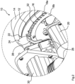
- the Fig. 1 to 3 show a singling device 10 during the adjustment of the size of the grain receiving recesses 16 of a singling disk 12.
- the singling disk 12 is designed in several parts and comprises a singling disk part 18a designed as a disk body and a singling disk part 18b designed as a perforated ring.
- the separating disc part 18a is connected to a drive shaft of a drive device 20 designed as an electric motor, which drives the separating disc 12 in rotation during the separating operation of the separating device 10.
- the separating disc part 18a is a rotating body made of plastic.
- the separating disc part 18b is a perforated circular ring made of metal.
- the separating disc part 18b is frictionally connected to the Separation disc part 18a is connected so that it can be driven in rotation by the drive device 20 together with the separation disc part 18a, provided that the separation disc part 18b is not locked.
- the singling disc 12 has several grain receiving recesses 16, which are designed to receive seeds for the purpose of singling.
- the singling disc parts 18a, 18b can be moved relative to one another by means of the drive device 20 in order to adjust the size of the grain receiving recesses 16.
- the multi-part singling disc 12 is arranged in a housing 14, whereby the housing 14 cannot be opened in order to adjust the size of the grain receiving recesses 16.
- the size of the grain receiving recesses 16 is adjusted using the actuators of the singling device 10 that are already present.
- a movable locking member 28 for locking the singling disc part 18b is to be brought into engagement with a stop element 32 on the singling disc part 18b.
- the singling disc part 18b which can be locked by means of the locking member 28, has several stop elements 32 evenly distributed over its circumference.
- the stop elements 32 are located on the outer circumference of the singling disc part 18b and are designed as projections which extend outwards in the radial direction.
- the locking member 28 is designed as a movable locking hook and is fastened to a holder 26 of a stripping device 22 of the singling device 10.
- the stripping device 22 has several movable stripping bodies 24, by means of which seeds can be stripped from the singling disc 12.
- the locking member 28 is movable relative to the lockable separating disc part 18b by means of a locking member actuator 30, so that the locking member 28 can be brought into engagement with a stop element 32 and disengaged from a stop element 32 by means of the locking member actuator 30.
- the locking member actuator 30 is designed as an electric motor and is simultaneously the positioning drive of the stripping device 22.
- the stripping bodies 24 can be positioned within a stripping area during the singling operation of the singling device 10, whereby by moving the stripping bodies 24 out of the stripping area, a stop element 32 of the lockable singling disk part 18b can be brought into abutment with the locking member 28.
- the locking member 28 attached to the stripping device 22 can be moved into the rotation path of the stop elements 32.
- the stripping bodies 24 were moved out of the stripping area in order to bring the locking member 28 into abutment with a stop element 32.
- the locking member 28 prevents the separating disk part 18b from rotating in an anti-clockwise direction. If the drive device 20 now rotates the non-lockable separating disk part 18a in an anti-clockwise direction, there is a relative movement of the separating disk parts 18a, 18b. This leads to a change in the size of the grain receiving recesses 16, since the relative movement of the separating disk parts 18a, 18b causes a different group of holes in the separating disk part 18b to be aligned with recesses 44 in the separating disk part 18a.
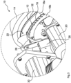
- the Fig. 3 to 6 also show a locking process by means of a locking member 28 designed as a locking hook.
- the separating disk 12 shown also has two separating disk parts 18a, 18b, which can be rotated relative to one another.
- the separating disk part 18a which is designed as a disk body, has a central receiving recess 34, via which the separating disk part 18a can be connected to a drive shaft of a drive device 20 designed as an electric motor.
- a torsionally rigid connection can be established between the drive shaft of the drive device 20 and the separating disk part 18a via the three groove-shaped recesses.
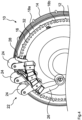
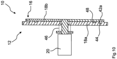
- the Fig.8 and the Fig.9 show two end position relative positions of the two separating disc parts 18a, 18b, which are predetermined by a limiting device 36.
- the limiting device 36 shown comprises an elongated hole 38 and a stop body 40 movable in the elongated hole 38.
- the stop body 40 is designed as a pin and is attached to the separating disc part 18a.
- the elongated hole 38 is part of the separating disc part 18b.
- the stop body 40 strikes the End position relative positions of the two separating disc parts 18a, 18b each on a boundary edge of the elongated hole 38.
- the singling disc part 18a is locked so that a rotary movement of the singling disc part 18b caused by the drive device 20 leads to an axial movement of the singling disc part 18a and to a relative movement of the singling disc parts 18a, 18b.
- the recesses 44 in the separating disc part 18a can be brought into line with different groups of holes 42a, 42b in the separating disc part 18b.
- the holes 42a, 42b of the different groups have different hole sizes, so that the size of the grain receiving recesses 16 can be adjusted by bringing the holes 42a, 42b of different groups into line.
- a spring 46 presses the separating disc part 18a axially against the separating disc part 18b, so that after the locking mechanism is released, the separating disc parts 18a, 18b are locked again via the locking lug 48.
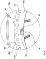
- the Fig. 12 shows a first side of a separating disk 12 on the left and a second side of the separating disk 12 on the right.
- the separating disk part 18b is designed as a disk body and has a first group of holes 42a with a first hole size and a second group of holes 42b with a second hole size. Holes 42a, 42b of different sizes are arranged adjacent to one another, so that a hole sequence with alternating hole sizes is produced.
- the separating disc part 18a which is designed as a disc body, has a plurality of recesses 44 of identical size, which are arranged on a circular path.
- the recesses 44 are either connected to the holes 42a of the first group or to the holes 42b of the second group in In this way, two different sizes of grain receiving recesses 16 can be set.
- the Fig. 13 shows a multi-part separating disc 12, wherein the separating disc parts 18a, 18b can be rotated relative to one another.
- a rod 52 is hinged to the separating disc part 18b, wherein the rod 52 is connected to a guided perforated rail 54.
- the guided perforated rail 54 has several holes 42a - 42c of different sizes, which can be brought into line with a recess 44 in the separating disc part 18a depending on the relative angle between the separating disc parts 18a, 18b.
- a guided perforated rail 54 which can be moved via a relative movement of the separating disc parts 18a, 18b, also allows the size of the grain receiving recesses 16 to be adjusted.
- a corresponding separating disc 12 preferably has several guided perforated rails 54, wherein each recess 44 is assigned a perforated rail 54.
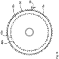
- the Fig. 14 and 15 show a singling device 10 with a freewheel.
- the singling disk part 18b designed as a disk body, is firmly connected to a drive shaft of the drive device 20.
- the singling disk part 18b designed as a disk body, is attached to the drive shaft of the drive device 20 with a freewheel and only rotates in the singling direction of rotation which is set in the singling operation of the singling device 10.
- the singling disk part 18a is locked by the locking member 28.
- another group of holes 42a, 42b can be brought into line with the recesses 44 in the singling disk part 18a in order to change the size of the grain receiving recesses 16.
Landscapes
- Life Sciences & Earth Sciences (AREA)
- Soil Sciences (AREA)
- Environmental Sciences (AREA)
- Adjustment And Processing Of Grains (AREA)
- Apparatuses For Bulk Treatment Of Fruits And Vegetables And Apparatuses For Preparing Feeds (AREA)
- Combined Means For Separation Of Solids (AREA)
Applications Claiming Priority (1)
| Application Number | Priority Date | Filing Date | Title |
|---|---|---|---|
| DE102019116716.7A DE102019116716A1 (de) | 2019-06-20 | 2019-06-20 | Vereinzelungseinrichtung |
Publications (3)
| Publication Number | Publication Date |
|---|---|
| EP3753388A2 EP3753388A2 (de) | 2020-12-23 |
| EP3753388A3 EP3753388A3 (de) | 2021-03-10 |
| EP3753388B1 true EP3753388B1 (de) | 2024-05-22 |
Family
ID=72243062
Family Applications (1)
| Application Number | Title | Priority Date | Filing Date |
|---|---|---|---|
| EP20401030.0A Active EP3753388B1 (de) | 2019-06-20 | 2020-05-19 | Vereinzelungseinrichtung |
Country Status (3)
| Country | Link |
|---|---|
| EP (1) | EP3753388B1 (pl) |
| DE (1) | DE102019116716A1 (pl) |
| PL (1) | PL3753388T3 (pl) |
Families Citing this family (2)
| Publication number | Priority date | Publication date | Assignee | Title |
|---|---|---|---|---|
| US11523554B2 (en) | 2019-01-25 | 2022-12-13 | Ag Leader Technology | Dual seed meter and related systems and methods |
| US11785881B2 (en) * | 2019-08-19 | 2023-10-17 | Ag Leader Technology | Adjustable seed meter and related systems and methods |
Family Cites Families (7)
| Publication number | Priority date | Publication date | Assignee | Title |
|---|---|---|---|---|
| US2505758A (en) * | 1944-12-29 | 1950-05-02 | Emil C Enebeck | Suction pickup rotor for seed dispensing machines |
| FR923995A (fr) * | 1946-02-15 | 1947-07-23 | Semoir à graines | |
| US4664290A (en) * | 1985-02-25 | 1987-05-12 | Deere & Company | Method and apparatus for precise positioning of a seed disk in a seed meter |
| FR2678472B1 (fr) * | 1991-07-03 | 1993-10-29 | Ecolasse Guy | Distributeur pneumatique monograine pour semoir permettant de semer des graines de differents calibres. |
| DE102004045654A1 (de) * | 2004-09-21 | 2006-03-23 | Amazonen-Werke H. Dreyer Gmbh & Co. Kg | Elektronische Überwachungseinrichtung |
| PL2807914T5 (pl) * | 2013-05-27 | 2019-09-30 | Kverneland As | Urządzenie monitorujące serce siewnika, serce siewnika i siewnik jednoziarnowy |
| DE102017118594A1 (de) * | 2017-08-15 | 2019-02-21 | Amazonen-Werke H. Dreyer Gmbh & Co. Kg | Vereinzelungsvorrichtung |
-
2019
- 2019-06-20 DE DE102019116716.7A patent/DE102019116716A1/de active Pending
-
2020
- 2020-05-19 EP EP20401030.0A patent/EP3753388B1/de active Active
- 2020-05-19 PL PL20401030.0T patent/PL3753388T3/pl unknown
Also Published As
| Publication number | Publication date |
|---|---|
| EP3753388A3 (de) | 2021-03-10 |
| EP3753388A2 (de) | 2020-12-23 |
| DE102019116716A1 (de) | 2020-12-24 |
| PL3753388T3 (pl) | 2024-07-22 |
Similar Documents
| Publication | Publication Date | Title |
|---|---|---|
| DE102012204740A1 (de) | Umformmaschine, insbesondere Biegemaschine | |
| EP2159172A1 (de) | Transportstern | |
| EP2665667A2 (de) | Spule zur aufnahme von wickelgut sowie spulenteilesystem | |
| EP3753388B1 (de) | Vereinzelungseinrichtung | |
| WO1988006672A1 (fr) | Support de stores | |
| DE4442533A1 (de) | Bohrvorrichtung | |
| EP0343347A1 (de) | Werkzeugrevolver | |
| DE102008017375A1 (de) | Bausatz für ein Handhabungssystem | |
| DE102007032328A1 (de) | Verfahren und Vorrichtung zur Montage eines Zahnriemens an einem Riementrieb | |
| EP2102509B1 (de) | Zuganker und damit zusammengespannte modulanordnung | |
| WO2003093013A2 (de) | Siebdruckmaschine und siebzylinder | |
| DE102022106921A1 (de) | Doppelkupplungsgetriebe mit Verschleißnachstellung | |
| WO2008106944A2 (de) | Pressstempel-befestigungsvorrichtung und verfahren zum befestigen eines stempels in einer presse | |
| EP3573791A1 (de) | Teilbarer rundtisch | |
| DE102012011180A9 (de) | Kupplungseinrichtung | |
| DE2854121C2 (de) | An ein Maschinenteil ansetzbare Vorrichtung zum Ausstechen von Ringlippen dort in Bohrungen eingestemmter Lagerbüchsen | |
| EP2886224B1 (de) | Gewinderollkopf | |
| EP1366873A1 (de) | Oberfräse | |
| EP3322641A1 (de) | Steuerstange zum verstellen von einem rotorblatt eines hubschraubers | |
| DE10238368A1 (de) | Doppelkupplung | |
| EP3322640B1 (de) | Steuerstange zum verstellen von einem rotorblatt eines hubschraubers | |
| DE102012224524A1 (de) | Kopplungsvorrichtung für eine Antriebsvorrichtung sowie Antriebseinrichtung | |
| EP1478589A1 (de) | Falztrommeln eines falzapparates | |
| DE102004011179B4 (de) | Rutschkupplung | |
| EP2369099A2 (de) | Türrosette |
Legal Events
| Date | Code | Title | Description |
|---|---|---|---|
| PUAI | Public reference made under article 153(3) epc to a published international application that has entered the european phase |
Free format text: ORIGINAL CODE: 0009012 |
|
| STAA | Information on the status of an ep patent application or granted ep patent |
Free format text: STATUS: THE APPLICATION HAS BEEN PUBLISHED |
|
| AK | Designated contracting states |
Kind code of ref document: A2 Designated state(s): AL AT BE BG CH CY CZ DE DK EE ES FI FR GB GR HR HU IE IS IT LI LT LU LV MC MK MT NL NO PL PT RO RS SE SI SK SM TR |
|
| AX | Request for extension of the european patent |
Extension state: BA ME |
|
| PUAL | Search report despatched |
Free format text: ORIGINAL CODE: 0009013 |
|
| AK | Designated contracting states |
Kind code of ref document: A3 Designated state(s): AL AT BE BG CH CY CZ DE DK EE ES FI FR GB GR HR HU IE IS IT LI LT LU LV MC MK MT NL NO PL PT RO RS SE SI SK SM TR |
|
| AX | Request for extension of the european patent |
Extension state: BA ME |
|
| RIC1 | Information provided on ipc code assigned before grant |
Ipc: A01C 7/04 20060101AFI20210204BHEP |
|
| RAP3 | Party data changed (applicant data changed or rights of an application transferred) |
Owner name: AMAZONEN-WERK H. DREYER SE & CO. KG |
|
| RAP3 | Party data changed (applicant data changed or rights of an application transferred) |
Owner name: AMAZONEN-WERKE H. DREYER SE & CO. KG |
|
| STAA | Information on the status of an ep patent application or granted ep patent |
Free format text: STATUS: REQUEST FOR EXAMINATION WAS MADE |
|
| 17P | Request for examination filed |
Effective date: 20210831 |
|
| RBV | Designated contracting states (corrected) |
Designated state(s): AL AT BE BG CH CY CZ DE DK EE ES FI FR GB GR HR HU IE IS IT LI LT LU LV MC MK MT NL NO PL PT RO RS SE SI SK SM TR |
|
| P01 | Opt-out of the competence of the unified patent court (upc) registered |
Effective date: 20230523 |
|
| GRAP | Despatch of communication of intention to grant a patent |
Free format text: ORIGINAL CODE: EPIDOSNIGR1 |
|
| STAA | Information on the status of an ep patent application or granted ep patent |
Free format text: STATUS: GRANT OF PATENT IS INTENDED |
|
| INTG | Intention to grant announced |
Effective date: 20240125 |
|
| GRAS | Grant fee paid |
Free format text: ORIGINAL CODE: EPIDOSNIGR3 |
|
| GRAA | (expected) grant |
Free format text: ORIGINAL CODE: 0009210 |
|
| STAA | Information on the status of an ep patent application or granted ep patent |
Free format text: STATUS: THE PATENT HAS BEEN GRANTED |
|
| AK | Designated contracting states |
Kind code of ref document: B1 Designated state(s): AL AT BE BG CH CY CZ DE DK EE ES FI FR GB GR HR HU IE IS IT LI LT LU LV MC MK MT NL NO PL PT RO RS SE SI SK SM TR |
|
| REG | Reference to a national code |
Ref country code: GB Ref legal event code: FG4D Free format text: NOT ENGLISH |
|
| REG | Reference to a national code |
Ref country code: CH Ref legal event code: EP |
|
| REG | Reference to a national code |
Ref country code: DE Ref legal event code: R096 Ref document number: 502020008057 Country of ref document: DE |
|
| REG | Reference to a national code |
Ref country code: IE Ref legal event code: FG4D Free format text: LANGUAGE OF EP DOCUMENT: GERMAN |
|
| REG | Reference to a national code |
Ref country code: SE Ref legal event code: TRGR |
|
| REG | Reference to a national code |
Ref country code: LT Ref legal event code: MG9D |
|
| REG | Reference to a national code |
Ref country code: NL Ref legal event code: MP Effective date: 20240522 |
|
| PG25 | Lapsed in a contracting state [announced via postgrant information from national office to epo] |
Ref country code: IS Free format text: LAPSE BECAUSE OF FAILURE TO SUBMIT A TRANSLATION OF THE DESCRIPTION OR TO PAY THE FEE WITHIN THE PRESCRIBED TIME-LIMIT Effective date: 20240922 |
|
| PG25 | Lapsed in a contracting state [announced via postgrant information from national office to epo] |
Ref country code: BG Free format text: LAPSE BECAUSE OF FAILURE TO SUBMIT A TRANSLATION OF THE DESCRIPTION OR TO PAY THE FEE WITHIN THE PRESCRIBED TIME-LIMIT Effective date: 20240522 |
|
| PG25 | Lapsed in a contracting state [announced via postgrant information from national office to epo] |
Ref country code: FI Free format text: LAPSE BECAUSE OF FAILURE TO SUBMIT A TRANSLATION OF THE DESCRIPTION OR TO PAY THE FEE WITHIN THE PRESCRIBED TIME-LIMIT Effective date: 20240522 Ref country code: HR Free format text: LAPSE BECAUSE OF FAILURE TO SUBMIT A TRANSLATION OF THE DESCRIPTION OR TO PAY THE FEE WITHIN THE PRESCRIBED TIME-LIMIT Effective date: 20240522 |
|
| PG25 | Lapsed in a contracting state [announced via postgrant information from national office to epo] |
Ref country code: GR Free format text: LAPSE BECAUSE OF FAILURE TO SUBMIT A TRANSLATION OF THE DESCRIPTION OR TO PAY THE FEE WITHIN THE PRESCRIBED TIME-LIMIT Effective date: 20240823 |
|
| PG25 | Lapsed in a contracting state [announced via postgrant information from national office to epo] |
Ref country code: PT Free format text: LAPSE BECAUSE OF FAILURE TO SUBMIT A TRANSLATION OF THE DESCRIPTION OR TO PAY THE FEE WITHIN THE PRESCRIBED TIME-LIMIT Effective date: 20240923 |
|
| PG25 | Lapsed in a contracting state [announced via postgrant information from national office to epo] |
Ref country code: NL Free format text: LAPSE BECAUSE OF FAILURE TO SUBMIT A TRANSLATION OF THE DESCRIPTION OR TO PAY THE FEE WITHIN THE PRESCRIBED TIME-LIMIT Effective date: 20240522 |
|
| PG25 | Lapsed in a contracting state [announced via postgrant information from national office to epo] |
Ref country code: ES Free format text: LAPSE BECAUSE OF FAILURE TO SUBMIT A TRANSLATION OF THE DESCRIPTION OR TO PAY THE FEE WITHIN THE PRESCRIBED TIME-LIMIT Effective date: 20240522 |
|
| PG25 | Lapsed in a contracting state [announced via postgrant information from national office to epo] |
Ref country code: LV Free format text: LAPSE BECAUSE OF FAILURE TO SUBMIT A TRANSLATION OF THE DESCRIPTION OR TO PAY THE FEE WITHIN THE PRESCRIBED TIME-LIMIT Effective date: 20240522 |
|
| PG25 | Lapsed in a contracting state [announced via postgrant information from national office to epo] |
Ref country code: PT Free format text: LAPSE BECAUSE OF FAILURE TO SUBMIT A TRANSLATION OF THE DESCRIPTION OR TO PAY THE FEE WITHIN THE PRESCRIBED TIME-LIMIT Effective date: 20240923 Ref country code: NO Free format text: LAPSE BECAUSE OF FAILURE TO SUBMIT A TRANSLATION OF THE DESCRIPTION OR TO PAY THE FEE WITHIN THE PRESCRIBED TIME-LIMIT Effective date: 20240822 Ref country code: NL Free format text: LAPSE BECAUSE OF FAILURE TO SUBMIT A TRANSLATION OF THE DESCRIPTION OR TO PAY THE FEE WITHIN THE PRESCRIBED TIME-LIMIT Effective date: 20240522 Ref country code: LV Free format text: LAPSE BECAUSE OF FAILURE TO SUBMIT A TRANSLATION OF THE DESCRIPTION OR TO PAY THE FEE WITHIN THE PRESCRIBED TIME-LIMIT Effective date: 20240522 Ref country code: IS Free format text: LAPSE BECAUSE OF FAILURE TO SUBMIT A TRANSLATION OF THE DESCRIPTION OR TO PAY THE FEE WITHIN THE PRESCRIBED TIME-LIMIT Effective date: 20240922 Ref country code: HR Free format text: LAPSE BECAUSE OF FAILURE TO SUBMIT A TRANSLATION OF THE DESCRIPTION OR TO PAY THE FEE WITHIN THE PRESCRIBED TIME-LIMIT Effective date: 20240522 Ref country code: GR Free format text: LAPSE BECAUSE OF FAILURE TO SUBMIT A TRANSLATION OF THE DESCRIPTION OR TO PAY THE FEE WITHIN THE PRESCRIBED TIME-LIMIT Effective date: 20240823 Ref country code: FI Free format text: LAPSE BECAUSE OF FAILURE TO SUBMIT A TRANSLATION OF THE DESCRIPTION OR TO PAY THE FEE WITHIN THE PRESCRIBED TIME-LIMIT Effective date: 20240522 Ref country code: ES Free format text: LAPSE BECAUSE OF FAILURE TO SUBMIT A TRANSLATION OF THE DESCRIPTION OR TO PAY THE FEE WITHIN THE PRESCRIBED TIME-LIMIT Effective date: 20240522 Ref country code: BG Free format text: LAPSE BECAUSE OF FAILURE TO SUBMIT A TRANSLATION OF THE DESCRIPTION OR TO PAY THE FEE WITHIN THE PRESCRIBED TIME-LIMIT Effective date: 20240522 Ref country code: RS Free format text: LAPSE BECAUSE OF FAILURE TO SUBMIT A TRANSLATION OF THE DESCRIPTION OR TO PAY THE FEE WITHIN THE PRESCRIBED TIME-LIMIT Effective date: 20240822 |
|
| PG25 | Lapsed in a contracting state [announced via postgrant information from national office to epo] |
Ref country code: DK Free format text: LAPSE BECAUSE OF FAILURE TO SUBMIT A TRANSLATION OF THE DESCRIPTION OR TO PAY THE FEE WITHIN THE PRESCRIBED TIME-LIMIT Effective date: 20240522 |
|
| PG25 | Lapsed in a contracting state [announced via postgrant information from national office to epo] |
Ref country code: EE Free format text: LAPSE BECAUSE OF FAILURE TO SUBMIT A TRANSLATION OF THE DESCRIPTION OR TO PAY THE FEE WITHIN THE PRESCRIBED TIME-LIMIT Effective date: 20240522 |
|
| PG25 | Lapsed in a contracting state [announced via postgrant information from national office to epo] |
Ref country code: CZ Free format text: LAPSE BECAUSE OF FAILURE TO SUBMIT A TRANSLATION OF THE DESCRIPTION OR TO PAY THE FEE WITHIN THE PRESCRIBED TIME-LIMIT Effective date: 20240522 |
|
| PG25 | Lapsed in a contracting state [announced via postgrant information from national office to epo] |
Ref country code: RO Free format text: LAPSE BECAUSE OF FAILURE TO SUBMIT A TRANSLATION OF THE DESCRIPTION OR TO PAY THE FEE WITHIN THE PRESCRIBED TIME-LIMIT Effective date: 20240522 Ref country code: SK Free format text: LAPSE BECAUSE OF FAILURE TO SUBMIT A TRANSLATION OF THE DESCRIPTION OR TO PAY THE FEE WITHIN THE PRESCRIBED TIME-LIMIT Effective date: 20240522 |
|
| PG25 | Lapsed in a contracting state [announced via postgrant information from national office to epo] |
Ref country code: SM Free format text: LAPSE BECAUSE OF FAILURE TO SUBMIT A TRANSLATION OF THE DESCRIPTION OR TO PAY THE FEE WITHIN THE PRESCRIBED TIME-LIMIT Effective date: 20240522 |
|
| PG25 | Lapsed in a contracting state [announced via postgrant information from national office to epo] |
Ref country code: SM Free format text: LAPSE BECAUSE OF FAILURE TO SUBMIT A TRANSLATION OF THE DESCRIPTION OR TO PAY THE FEE WITHIN THE PRESCRIBED TIME-LIMIT Effective date: 20240522 Ref country code: SK Free format text: LAPSE BECAUSE OF FAILURE TO SUBMIT A TRANSLATION OF THE DESCRIPTION OR TO PAY THE FEE WITHIN THE PRESCRIBED TIME-LIMIT Effective date: 20240522 Ref country code: RO Free format text: LAPSE BECAUSE OF FAILURE TO SUBMIT A TRANSLATION OF THE DESCRIPTION OR TO PAY THE FEE WITHIN THE PRESCRIBED TIME-LIMIT Effective date: 20240522 Ref country code: EE Free format text: LAPSE BECAUSE OF FAILURE TO SUBMIT A TRANSLATION OF THE DESCRIPTION OR TO PAY THE FEE WITHIN THE PRESCRIBED TIME-LIMIT Effective date: 20240522 Ref country code: DK Free format text: LAPSE BECAUSE OF FAILURE TO SUBMIT A TRANSLATION OF THE DESCRIPTION OR TO PAY THE FEE WITHIN THE PRESCRIBED TIME-LIMIT Effective date: 20240522 Ref country code: CZ Free format text: LAPSE BECAUSE OF FAILURE TO SUBMIT A TRANSLATION OF THE DESCRIPTION OR TO PAY THE FEE WITHIN THE PRESCRIBED TIME-LIMIT Effective date: 20240522 |
|
| REG | Reference to a national code |
Ref country code: DE Ref legal event code: R097 Ref document number: 502020008057 Country of ref document: DE |
|
| PLBE | No opposition filed within time limit |
Free format text: ORIGINAL CODE: 0009261 |
|
| STAA | Information on the status of an ep patent application or granted ep patent |
Free format text: STATUS: NO OPPOSITION FILED WITHIN TIME LIMIT |
|
| PGFP | Annual fee paid to national office [announced via postgrant information from national office to epo] |
Ref country code: SE Payment date: 20250310 Year of fee payment: 6 |
|
| PG25 | Lapsed in a contracting state [announced via postgrant information from national office to epo] |
Ref country code: SI Free format text: LAPSE BECAUSE OF FAILURE TO SUBMIT A TRANSLATION OF THE DESCRIPTION OR TO PAY THE FEE WITHIN THE PRESCRIBED TIME-LIMIT Effective date: 20240522 |
|
| PGFP | Annual fee paid to national office [announced via postgrant information from national office to epo] |
Ref country code: FR Payment date: 20250310 Year of fee payment: 6 |
|
| 26N | No opposition filed |
Effective date: 20250225 |
|
| PGFP | Annual fee paid to national office [announced via postgrant information from national office to epo] |
Ref country code: DE Payment date: 20250325 Year of fee payment: 6 Ref country code: PL Payment date: 20250314 Year of fee payment: 6 |
|
| PGFP | Annual fee paid to national office [announced via postgrant information from national office to epo] |
Ref country code: IT Payment date: 20250422 Year of fee payment: 6 |
|
| PGFP | Annual fee paid to national office [announced via postgrant information from national office to epo] |
Ref country code: AT Payment date: 20250425 Year of fee payment: 6 |
|
| REG | Reference to a national code |
Ref country code: CH Ref legal event code: H13 Free format text: ST27 STATUS EVENT CODE: U-0-0-H10-H13 (AS PROVIDED BY THE NATIONAL OFFICE) Effective date: 20251223 |
|
| PG25 | Lapsed in a contracting state [announced via postgrant information from national office to epo] |
Ref country code: LU Free format text: LAPSE BECAUSE OF NON-PAYMENT OF DUE FEES Effective date: 20250519 |
|
| PG25 | Lapsed in a contracting state [announced via postgrant information from national office to epo] |
Ref country code: CH Free format text: LAPSE BECAUSE OF NON-PAYMENT OF DUE FEES Effective date: 20250531 |
|
| GBPC | Gb: european patent ceased through non-payment of renewal fee |
Effective date: 20250519 |
|
| REG | Reference to a national code |
Ref country code: BE Ref legal event code: MM Effective date: 20250531 |
|
| PG25 | Lapsed in a contracting state [announced via postgrant information from national office to epo] |
Ref country code: MC Free format text: LAPSE BECAUSE OF FAILURE TO SUBMIT A TRANSLATION OF THE DESCRIPTION OR TO PAY THE FEE WITHIN THE PRESCRIBED TIME-LIMIT Effective date: 20240522 |