EP3753303B1 - Verfahren und vorrichtung zur auswahl von netzwerk-slices, sitzungsverwaltung und funktionen auf benutzerebene - Google Patents
Verfahren und vorrichtung zur auswahl von netzwerk-slices, sitzungsverwaltung und funktionen auf benutzerebene Download PDFInfo
- Publication number
- EP3753303B1 EP3753303B1 EP19706838.0A EP19706838A EP3753303B1 EP 3753303 B1 EP3753303 B1 EP 3753303B1 EP 19706838 A EP19706838 A EP 19706838A EP 3753303 B1 EP3753303 B1 EP 3753303B1
- Authority
- EP
- European Patent Office
- Prior art keywords
- entity
- session
- message
- management
- data
- Prior art date
- Legal status (The legal status is an assumption and is not a legal conclusion. Google has not performed a legal analysis and makes no representation as to the accuracy of the status listed.)
- Active
Links
Images


Classifications
-
- H—ELECTRICITY
- H04—ELECTRIC COMMUNICATION TECHNIQUE
- H04W—WIRELESS COMMUNICATION NETWORKS
- H04W76/00—Connection management
- H04W76/10—Connection setup
-
- H—ELECTRICITY
- H04—ELECTRIC COMMUNICATION TECHNIQUE
- H04W—WIRELESS COMMUNICATION NETWORKS
- H04W48/00—Access restriction; Network selection; Access point selection
- H04W48/18—Selecting a network or a communication service
-
- H—ELECTRICITY
- H04—ELECTRIC COMMUNICATION TECHNIQUE
- H04W—WIRELESS COMMUNICATION NETWORKS
- H04W72/00—Local resource management
- H04W72/04—Wireless resource allocation
-
- H—ELECTRICITY
- H04—ELECTRIC COMMUNICATION TECHNIQUE
- H04W—WIRELESS COMMUNICATION NETWORKS
- H04W8/00—Network data management
- H04W8/02—Processing of mobility data, e.g. registration information at HLR [Home Location Register] or VLR [Visitor Location Register]; Transfer of mobility data, e.g. between HLR, VLR or external networks
Definitions
- the present disclosure relates generally to the selection of network slice, session management, and user plane functions for mobile networks.
- Proposal for AMF and MME selecting entities dedicated for interworking is directed to a mechanism to support interworking between 5GC and EPC.
- PCF + PCRF, PGW-C + SMF and UPF + PGW-U which are dedicated for interworking are defined. It is proposed to introduce a mechanism to avoid unnecessary upgrade or anchoring of legacy LTE UEs or UEs not requiring interworking to dedicated entities, i.e. PCF + PCRF, PGW-C + SMF and UPF + PGW-U are selected by AMF and MME only for 5G UEs that support and require interworking function.
- 3rd Generation Partnership Project; Technical Specification Group Services and System Aspects; System Architecture for the 5G System; Stage 2 (Release 15)"; 3GPP DRAFT; 23501-F00 is directed to the architecture for a 5G System, which is defined to support data connectivity and services enabling deployments to use techniques such as e.g. Network Function Virtualization and Software Defined Networking.
- the 5G System architecture leverages service-based interactions between Control Plane (CP) Network Functions where identified.
- CP Control Plane
- a control plane (CP) entity for mobility management may select a CP entity for session management for a session of a user equipment (UE) based on a first set of data items.
- the CP entity for mobility management may further select a user plane (UP) entity for the session of the UE based on a second set of data items, where second set of data items include at least some of the same data items of the first set.
- the CP entity for mobility management may send, to the selected CP entity for session management, a message including an identity or indication of the selected UP entity for the session of the UE.
- the selected CP entity for session management may choose the identified or indicated UP entity in the message for use in the session of the UE.
- the CP entity for mobility management is an access and mobility management function (AMF) of a 5G mobile network
- the selected CP entity for session management is a session management function (SMF) instance
- the selected UP entity is a user plane function (UPF) instance.
- the identity or indication of the selected UPF instance may be included in a data field for a data network name (DNN) of a create session request message which is sent to the selected SMF instance.
- DNN data network name
- the data retrieval and NF selection functions are delegated to a network repository function (NRF) of the 5G mobile network.
- NRF network repository function
- the CP entity for mobility management is a mobility management entity (MME) of a 4G / LTE based mobile network, where the CP entity for session management is a gateway - control plane (GW-C).
- MME mobility management entity
- GW-C gateway - control plane
- the identity or indication of the selected UP entity may be included in a data field for an access point name (APN) of a create session request message which is sent to the selected GW-C.
- APN access point name
- a CP entity for session management may receive, from a CP entity for mobility management, a message which includes a create session request for creating a session for a UE.
- the CP entity for session management may identify from the message an identity or indication of a user plane (UP) entity.
- the CP entity for session management may select, for use in the session, a UP entity corresponding to or based on the identity or indication of the UP entity from the message.
- the CP entity for session management may send, to the selected UP entity, a message which includes a session establishment request for establishing the session.
- UP user plane
- the CP entity for session management may be a session management function (SMF) of a 5G mobile network, where the identity or indication of the selected UP entity is extracted from a data field for a data network name (DNN) of the create session request.
- the CP entity for mobility management may be a gateway (GW) control plane (CP) entity (GW-C) of a 4G / LTE based mobile network, where the identity or indication of the selected UP entity is extracted from a data field for an access point name (APN) of the create session request.
- GW gateway
- CP control plane
- API access point name
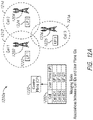
- FIG. 1A is an illustration of a basic network architecture 100a of a 5G mobile network.
- the network architecture 100a of the 5G mobile network is configured to support network slicing.
- network architecture 100a includes common control network functions (CCNF) 105 and a plurality of slice-specific core network functions 106.
- CCNF common control network functions
- a user equipment (UE) 102 may obtain access to the mobile network via an access network (AN) 104, which may be a radio access network (RAN).
- AN access network
- RAN radio access network
- CCNF 105 includes a plurality of network functions (NFs) which commonly support all sessions for UE 102.
- UE 102 may be connected to and served by a single CCNF 105 at a time, although multiple sessions of UE 102 may be served by different slice-specific core network functions 106.
- CCNF 105 may include, for example, an access and mobility management function (AMF) and a network slice selection function (NSSF).
- AMF access and mobility management function
- NSSF network slice selection function
- UE-level mobility management, authentication, and network slice instance selection are examples of common functionalities provided by CCNF 105.
- CP NFs 108 are separated into control plane (CP) NFs 108 and user plane (UP) NFs 110.
- the user plane carries user traffic while the control plane carries network signaling.
- CP NFs 108 are shown in FIG. 1A as CP NF 1 through CP NF n
- UP NFs 110 are shown in FIG. 1A as UP NF 1 through UP NF n.
- CP NFs 108 may include, for example, a session management function (SMF)
- UP NFs 110 may include, for example, a user plane function (UPF).
- SMF session management function
- UPF user plane function
- FIG. 1B is an illustration of a more detailed network architecture 100b of the 5G mobile network of FIG. 1A .
- network architecture 100b for a 5G mobile network may include an authentication server function (AUSF) 116, a unified data management (UDM) 118 (having a unified data repository or UDR), an AMF 112, a policy control function (PCF) 114, an SMF 120a, and a UPF 122a.
- PCF 114 may connect with one or more application functions such as an application function (AF) 124.
- UPF 122a may connect with one or more data networks (DNs) 109 to which an application server (AS) may be connected.
- a plurality of interfaces N1 through N15 shown in FIG. 1 may define the communications and/or protocols between each of the entities, as described in the relevant (evolving) standards documents.
- UPF 122a is part of the user plane and all other NFs (i.e. AMF 112, SMF 120a, PCF 114, AUSF 116, and UDM 118) are part of the control plane. Separating user and control planes guarantees that each plane resource to be scaled independently. It also allows UPFs to be deployed separately from CP functions in a distributed fashion.
- the NFs in the CP are modularized functions; for example, AMF and SMF are independent functions allowing for independent evolution and scaling.
- NFs such as SMF 120a and UPF 122a of FIG. 1B may be provided as specific instances in a first network slice (e.g. network slice 1). Additional instances of NFs for additional network slices may be provided as well, as illustrated by SMF 120b and UPF 122b provided as additional specific instances in a second network slice (e.g. network slice 2).
- the network generally deploys a network slice based on a network slice selection assistance information (NSSAI) provided by UE 102.
- NSSAI network slice selection assistance information
- the NSSAI is used by RAN 104 to select the CCNF 105.
- the NSSF in CCNF 105 selects the network slice instance.
- network slice instance selection may be based on the NSSAI, the data network name (DNN) of the session, subscription data of UE 102, and other parameters.
- An attach accept message from the network includes an accepted or allowed NSSAI for UE 102.
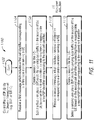
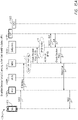
- FIG. 2 is a process flow diagram 200 for describing a method of selecting network slice, session management and user plane functions for use in a session of a UE.
- UE 102 may send to AMF 112 a message which includes a session establishment request (step 1 of FIG. 2 ).
- the session establishment request is for use in creating a packet data unit (PDU) session for UE 102.
- AMF 112 may retrieve a first set of data items to assist in establishing a session that is appropriate for UE 102 (step 2 of FIG. 2 ).
- the first set of data items may include, for example, subscription data, profile data, an identity of a dedicated core network (DCN), and a hint from UE 102.
- DCN dedicated core network
- At least some of the first set of data items may be retrieved from a DB (e.g. from a Unified Data Repository or UDR of UDM 118).
- AMF 112 may select an SMF instance for the session based on the first set of data items (step 3 of FIG. 2 ). Here, an identity of the selected SMF instance 120a is obtained. The selected SMF instance 120a will be used to carry signaling for the session for UE 102. AMF 112 may select an SMF instance by consulting a network repository function (NRF) 202 which stores / provides a list of available network functions together with the services offered by those functions. In some implementations, NRF 202 may perform steps 2 and 3 (i.e. AMF 112 may delegate the data retrieval and selection of the SMF instance to NRF 202). Using the identity of the selected SMF instance, AMF 112 may send to the selected SMF 120a a message which includes a create session request (step 4 of FIG. 2 ).
- NRF network repository function
- SMF 120a may retrieve a second set of data items to assist in establishing the PDU session for UE 102 (step 5 of FIG. 2 ).
- the second set of data items may include, for example, subscription data, UP capacity, UP location, and path latency. At least some of the second set of data items may be retrieved from a DB (e.g. from the UDR of UDM 118).
- SMF 120a may select a UPF instance for the session based on the second set of data items (step 6 of FIG. 2 ).
- an identity of the selected UPF instance 122a is obtained.
- SMF 120a may select a UPF instance by consulting NRF 202 which stores / provides a list of available functions together with the services offered by those functions.
- NRF 202 may perform steps 5 and 6 (i.e. SMF 120a may delegate the data retrieval and selection of the UPF instance to NRF 202).
- SMF 120a may send to the selected UPF 122a a message which includes a session establishment/modification request (step 7 of FIG. 2 ).
- the selected UPF 122a will be used to carry traffic of the session for UE 102.
- first and the second set of data items in the process of FIG. 2 may include at least some or many of the same data items (e.g. data items retrieved from one or more databases).
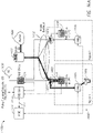
- FIG. 3 is a process flow diagram 300 for describing a more efficient method of selecting network slice, session management and user plane functions for use in a session of a UE according to some implementations of the present disclosure.
- the entities, functions, and interfaces of the 5G mobile network of FIGs. 1a and 1b may be configured in accordance with the relevant (evolving) standards, with modification, adaptation, and/or additions provided in accordance with the techniques of the present disclosure.
- UE 102 may send to AMF 112 a message which includes a session establishment request (step 1 of FIG. 3 ).
- the session establishment request is for use in establishing a PDU session for UE 102.
- AMF 112 may retrieve a set of data items to assist in establishing a PDU session that is appropriate for UE 102 (step 2 of FIG. 3 ). At least some of the set of data items may be retrieved from one or more databases (e.g. from a Unified Data Repository of UDM 118).
- the set of data items may include a first set (or subset) of data items for selecting an appropriate SMF instance, and a second set (or subset) of data items for selecting an appropriate UPF instance.
- first and the second sets (or subsets) of data items may be different and distinct sets (or subsets) of data items, the first and the second sets (or subsets) of data items may include at least some or many of the same data items.
- AMF 112 may select an SMF instance for the session based on the first set (or subset) of these data items (step 3 of FIG. 3 ).
- the first set (or subset) of data items may include, for example, subscription data, profile data, an identity of a DCN, and a hint from UE 102.
- the SMF instance may be selected by performing a first function or algorithm which uses the first set (or subset) of data items as inputs.
- an identity of the selected SMF instance 120a is obtained.
- the selected SMF instance 120a will be used to carry signaling for the session for UE 102.
- AMF 112 may further select a UPF instance for the session based on the second set (or subset) of these data items (step 4 of FIG. 3 ).
- the second set (or subset) of data items may include, for example, subscription data, policy data, identity of the selected SMF, UP capacity, UP location, load, and path latency.
- the UPF instance may be selected by performing a second function or algorithm which uses the second set (or subset) of data items as inputs. Here, an identity of the selected UPF instance 122a is obtained. The selected UPF 122a will be used to carry traffic of the session for UE 102.
- AMF 112 may select an SMF instance and/or a UPF instance by consulting NRF 202 which stores / provides a list of available network functions together with the services offered by those functions.
- NRF 202 may perform steps 2, 3, and/or 4 (i.e. AMF 112 may delegate the data retrieval and selection of the SMF instance and/or the UPF instance to NRF 202).
- data items e.g. subscription data and policy data
- data items are retrieved only one time (i.e. a single time) for the selection of both the SMF instance and the UPF instance (i.e. for steps 3 and 4 of FIG. 3 ).
- AMF 112 may send to the selected SMF 120a a message which includes a create session request (step 5 of FIG. 3 ).
- AMF 112 may also provide the identity or indication of the selected UPF instance 122a to SMF 120 (step 6 of FIG. 3 ).
- the message in step 5 includes the identity or indication of the selected UPF instance 122a.
- SMF instance 120a may receive the message from AMF 112 and identifies the AMF-selected UPF instance 122a for the session for UE 102. Using the identity of selected UPF instance 122a, SMF 120a may send to the selected UPF 122a a message which includes a session establishment/modification request (step 7 of FIG. 3 ). Again, selected UPF 122a will be used to carry traffic of the session for UE 102.
- the selected UPF 122a for the session is identified by the SMF 120a without the SMF 120a having to separately retrieve data items and perform selection.
- the first and the second sets of data items may include some or many of the same data items (e.g. retrieved from one or more databases), and therefore performing the selection of SMF and UPF instances together at the AMF 112 provides for increased processing efficiency.
- UPF instance selection A few examples of UPF instance selection are noted for illustration.
- an edge node may be selected for a subscribed video delivery service.
- a different type of edge node may be selected for an AR-type service where low latency is a more important factor.
- a more centralized UPF may be selected when a user plane offering complex service chaining is required for a service.
- FIG. 4 is a flowchart 400 for describing a method an efficient method of selecting network slice, session management and user plane functions for a session of a UE according to some implementations of the present disclosure.
- the method may be performed by a NF entity, such as an AMF entity, of a 5G mobile network.
- the AMF entity may receive from a UE a message which includes a session establishment request (step 404 of FIG. 4 )).
- the session establishment request may be for use in establishing a PDU session for the UE.
- AMF 112 may retrieve a set of data items to assist in establishing a PDU session that is appropriate for UE 102 (step 406 of FIG. 4 ).
- the set of data items may include, for example, subscription data and profile data associated with UE 102. At least some of the data items may be retrieved from one or more databases (e.g. from a UDR of UDM 118).
- the set of data items may include a first set (or subset) of data items for selecting an appropriate SMF instance and a second set (or subset) of data items for selecting an appropriate UPF instance.
- first and the second sets (or subsets) of data items may be different and distinct sets (or subsets) of data items, the first and the second sets of data items may include at least some or many of the same data items.
- the AMF entity may select an SMF instance for the session based on the first set of data items (step 408 of FIG. 4 ).
- the first set of data items may include, for example, subscription data, profile data, an identity of a DCN, and a hint from UE 102.
- the SMF instance may be selected by performing a first function or algorithm which uses the first set of data items as inputs. Here, an identity of the selected SMF instance is obtained. The selected SMF instance will be used to carry the signaling for the session for UE.
- the AMF entity may further select a UPF instance for the session based on the second set of data items (step 410 of FIG. 4 ).
- the second set of data items may include, for example, subscription data, policy data, identity of the selected SMF, UP capacity, UP location, load, and path latency.
- the UPF instance may be selected by performing a second function or algorithm which uses the second set of data items as inputs. Here, an identity of the selected UPF instance is obtained. The selected UPF will be used to carry traffic of the session for the UE.
- the AMF entity may select an SMF instance and/or a UPF instance by consulting an NRF which stores / provides a list of available network functions together with the services offered by those functions.
- the NRF may perform steps 406, 408, and 410 of FIG. 4 (i.e. the AMF entity may delegate the data retrieval and selection of the SMF instance and/or the UPF instance to the NRF).
- data items e.g. subscription data and policy data
- data items are retrieved only one time (i.e. a single time) for the selection of both the SMF instance and the UPF instance (i.e. for steps 408 and 410 of FIG. 4 ).
- the AMF entity may send to the selected SMF instance a message which includes a create session request (step 412 of FIG. 4 ).
- AMF 112 may also provide the identity or indication of the selected UPF instance to the selected SMF instance (step 414 of FIG. 4 ).
- the selected UPF instance will be used to carry traffic in the session for the UE.
- the message of step 412 includes the identity or indication of the selected UPF instance.
- the selected SMF instance may receive the message from the AMF entity and identify the AMF-selected UPF instance for use in the session for the UE.
- steps 412 and 414 are performed with use of the technique described below in relation to FIG. 5 .
- a suitable, selected UPF instance for the session is identified by the SMF without the SMF having to separately retrieve data items and perform the selection.
- the first and the second sets of data items may include some or many of the same data items (e.g. retrieved from one or more databases), and therefore performing the selection of SMF and UPF instances together at the AMF provides for increased processing efficiency.
- FIG. 5 is a flowchart 500 for describing a method for use in selecting network slice, session management and user plane functions for a session of a UE according to some implementations of the present disclosure.
- the method may be performed by an NF entity, such as an AMF entity, of a 5G mobile network.
- the method of FIG. 5 involves a technique which may be used to perform steps 412 and 414 of FIG. 4 .
- the AMF entity may begin the method after the selection of an SMF instance and the selection of a UPF instance for the session for the UE (e.g. see steps 406, 408, and 410 of FIG. 4 ).
- the AMF entity may construct a message which includes a create session request (step 504 of FIG. 5 ).
- the create session request is for use in creating a PDU session for the UE.
- the AMF entity may provide an identity of indication of the selected UP instance in the message (step 506 of FIG. 5 ). More particularly, the identity or indication of the selected UPF instance may be provided in a data field for a DNN in the create session request.
- the identity or indication of the selected UPF instance may be provided together with the DNN in the data field.
- the AMF entity may send to the selected SMF instance the message which includes the create session request having the identity of indication of the selected UPF instance (step 508 of FIG. 5 ).
- FIG. 6 An illustrative example of the constructed message of steps 504 and 506 of FIG. 5 is shown in FIG. 6 .
- a message 602 which includes a create session request 602 having a data field 604 for a DNN which includes the DNN and the identity or indication of the selected UPF instance is shown.
- the identity or indication of the selected UPF instance may be inserted as part of the DNN.
- the DNN is "internet.operator.com” and the selected UPF instance is "AR2" (of AR1, AR2, ... ARn)
- data field 604 may be internet-AR2.operator.com.
- the AMF entity may insert or otherwise provide "AR2" in data field 604, and the SMF entity may extract "AR2" from data field 604.
- the DNN includes metadata which indicates the selected UPF instance.
- FIG. 7 is a flowchart 700 for describing a method for use in selecting network slice, session management and user plane functions for a session of a UE according to some implementations of the present disclosure.
- the method of FIG. 7 may be performed by an NF entity, such as an SMF entity, of a 5G mobile network.
- the method of FIG. 7 involves a technique at an SMF entity which may be performed in combination with the technique at the AMF entity of FIGs. 4 , 5, and 6 . More particularly, the method of FIG. 7 may begin after steps 412 and 414 of FIG. 4 , and/or step 508 of FIG. 5 .
- an SMF entity may receive from an AMF entity a message which includes a create session request (step 704 of FIG. 7 ).
- the create session request is for use in creating the PDU session for the UE.
- the SMF entity may extract from the message an identity or indication of a selected UPF instance (step 706 of FIG. 7 ). More particularly, the SMF entity may extract the identity or indication of the selected UPF instance from a data field for a data network name (DNN).
- the SMF entity may identity or select a UPF instance corresponding to the extracted identity or indication from the message (step 708 of FIG. 7 ).
- the SMF entity may send to the identified UPF instance a message which includes a session establishment/modification request (step 710 of FIG. 7 ). The selected UPF will be used to carry traffic of the session for the UE.
- FIG. 8 is a flowchart 800 for more generally describing the technique of FIGs. 3-7 and its applicability to not only a 5G mobile network, but to other networks such as a 4G / Long Term Evolution (LTE) network.
- LTE Long Term Evolution
- the technique of FIGs. 3-7 applied to an LTE-based network replaces the AMF entity of the 5G mobile network with a mobility management entity (MME), and the SMF entity of the 5G mobile network with a gateway (GW) control plane (C) entity (GW-C).
- MME mobility management entity
- C gateway
- a control plane (CP) entity for mobility management e.g. an AMF or an MME
- a message which includes a request for creating a session for a UE may be received (step 804 of FIG. 8 ).
- a set of data items for use in creating the session for the UE may be retrieved (step 806 of FIG. 8 ).
- a CP entity for session management e.g. an SMF or a GW-C
- a CP entity for session management may be selected for the session based on some or a subset of the retrieved data items (step 808 of FIG. 8 ).
- a user plane (UP) entity e.g. a UPF or GW-U
- UPF User Planed Planed data plane
- a message which includes a create session request may be sent to the selected CP entity for session management (i.e. the SMF or GW-C) (step 812 of FIG. 8 ).
- An identity or indication of the selected UP entity is provided to the selected CP entity for session management (step 814 of FIG. 8 ).
- the identity or indication may be provided in a message, such as a message which includes a create session request (e.g. in a data field for a data network name (DNN) or an application point name (APN)).
- the selected CP entity for session management may identity or select a UP entity for the session based on the provided identity or indication, or may identity or select a UP entity that corresponds to the provided identity or indication.
- the additional methods and apparatus may be for use in selecting / reselecting a user plane (UP) entity and/or an IP address for a session for a UE.
- the techniques may alternatively be referred to as techniques for "re-siting" an IP anchor, where re-siting is a process of re-selecting the UP function or entity such that it is more geographically appropriate for the session.
- the IP anchor may be re-sited to a new, closer (e.g. the closest) UP.
- the present techniques may also provide the desired effect of changing the IP address on UP re-siting.
- FIG. 9 is a flowchart 900 for describing a method for use in selecting / reselecting a UP entity (e.g. an UPF or GW-U) and/or an IP address for a session for a UE in a mobile network.
- the method of FIG. 9 may be performed by a control plane (CP) entity for session management (e.g. an SMF or GW-C).
- CP control plane
- a message which includes a request for creating a session for a UE may be received (step 904 of FIG. 9 ).
- the UE is being served by a first base station in a first cell.
- a first UP entity may be selected for the session based on a (received) first cell identifier of the first base station (step 906 of FIG. 9 ).
- the first cell identifier may be, for example, a cell ID or a cell global identification (eCGI).
- a first IP address may be selected and assigned to the UE for the session, and this first IP address is sent to the UE for configuration.
- the first IP address may be selected from a first pool of IP addresses allocated to the selected first UP entity.
- the selection in step 906 may be performed with use of a mapping table which includes a plurality of cell identifiers mapped to a respective plurality of UP identifiers of UP entities. Each cell identifier may correspond to a UP identifier of a UP entity; alternatively, each one of a plurality of sets of cell identifiers of a region may correspond to a UP identifier of a UP entity. In some implementations, the selection in step 906 may be performed by selecting the UP having the UP identifier that corresponds to the received cell identifier with reference to the mapping table.
- the selection in step 906 may be performed based on factors or considerations in addition to the received cell identifier and/or selected (e.g. suggested or prioritized) user plane. Mapping and mapping tables are illustrated in more detail later in relation to FIGs. 12A-12B .
- the UE may be relocated to a second cell of a second base station.
- a message which includes a handover indication of a handover of the UE from the first base station to the second base station may be received (step 908 of FIG. 9 ).
- the message may be or include a modify bearer request which includes a second cell identifier (e.g. a cell ID, or eCGI) of the second base station.
- a second cell identifier e.g. a cell ID, or eCGI
- a message which includes a detach request including a reactivation request may be sent to the UE (step 910 of FIG. 9 ).
- This message may instruct the UE to disconnect and re-attach to the network, and re-establish the connection.
- the UE may respond to the message by detaching and reattaching to the network with a (new) request for (re-)creating a session. Accordingly, a message which includes a request for creating a session for a UE may be received (step 912 of FIG. 9 ).
- the UE is being served by the second base station in the second cell.
- a second UP entity may be selected for the session based on a (received) second cell identifier of the second base station (step 914 of FIG. 9 ).
- the second cell identifier may be, for example, a cell ID or a eCGI.
- a second IP address may be selected and assigned to the UE for the newly-created session, and this second IP address is sent to the UE for configuration.
- the second IP address may be selected from a second pool of IP addresses allocated to the selected second UP entity.
- the selection in step 914 may be performed with use of the mapping table which includes the plurality of cell identifiers mapped to the respective plurality of UP identifiers of UP entities. In some implementations, the selection in step 914 may be performed by selecting the UP having the UP identifier that corresponds to the received cell identifier with reference to the mapping table. In other implementations, the selection in step 914 may be performed based on factors or considerations in addition to the received cell identifier and/or selected (e.g. suggested or prioritized) UP. Again, mapping and mapping tables are illustrated in more detail later in relation to FIGs. 12A-12B .
- step 910 (and resulting steps 912 and 914) is performed (e.g. only) if an identified latency of communications in the session is outside of a threshold latency value. Also in some implementations of FIG. 9 , step 910 (and resulting steps 912 and 914) is performed (e.g. only) if communications in the session are substantially inactive or outside of a communication activity threshold value; here, the request for detachment may be delayed until communications in the session are substantially inactive. Further in some implementations of FIG. 9 , step 910 is performed based on one or more other factors or parameters in addition to handover and/or use of the mapping table.
- FIG. 10 is a flowchart 1000 for describing a method for use in selecting / reselecting a UP entity and/or an IP address for a session for a UE, which may be performed by the UE, and may be performed by the UE in combination with the method of the CP entity of FIG. 9 previously described.
- one or more messages which include a request to attach and a request to create a session are sent to a mobile network via a first base station (step 1004 of FIG. 10 ).
- a connection and session are established, where data packets are communicated via the first base station (step 1006 of FIG. 10 ).
- the newly-created session involves a first UP entity associated with the first base station or a region thereof (e.g. selected by the CP entity for session management with use of the mapping table described herein).
- the session also involves use of a first IP address that is received and configured in the UE; the first IP address may be selected from a first pool of IP addresses allocated to the selected first UP entity.
- the UE may be relocated to a second cell of a second base station.
- a message which includes a handover instruction for a handover of the UE from the first base station to the second base station may be received (step 1008 of FIG. 10 ).
- the UE may now be served by the second base station in the second cell.
- a message which includes a detach request including a reactivation request may be received (step 1010 of FIG. 10 ).
- This message may instruct the UE to disconnect and re-attach to the network, and re-establish the connection.
- the UE may respond to the message by detaching and reattaching to the network with a (new) request for (re-)creating a session.
- one or more messages which include a request to attach and a request to create a session may be sent to a mobile network via the second base station (step 1012 of FIG. 10 ).
- a new connection and new session are established, where data packets are communicated via the second base station (step 1014 of FIG. 10 ).
- the newly-created session involves a second UP entity associated with the second base station or a region thereof (e.g. selected by the CP entity for session management with use of the above-described mapping table).
- the session may also involve use of a second IP address that is received and configured in the UE; the second IP address may be selected from a second pool of IP addresses allocated to the selected second UP entity.
- step 1010 (and resulting steps 1012 and 1014) is performed (e.g. only) if an identified latency of communications in the session is outside of a threshold latency value. Also in some implementations of FIG. 10 , step 1010 (and resulting steps 1012 and 1014) is performed (e.g. only) if communications in the session are substantially inactive or outside of a communication activity threshold value; where the request for detachment may be delayed until communications in the session are substantially inactive. Further in some implementations of FIG. 10 , step 1010 is performed based on one or more other factors or parameters in addition to handover and/or use of the mapping table.
- FIG. 11 is a flowchart 1100 for describing a more general method for use in selecting / reselecting a UP entity and/or an IP address for a session of a UE, which may be performed by a CP entity for session management (e.g. SMF or GW-C). This method may be more general than the method performed by the CP entity for session management described in relation to FIG. 9 .
- a CP entity for session management e.g. SMF or GW-C
- a first message may be received (step 1104 of FIG. 11 ).
- the first message may include a first cell identifier corresponding to a first base station serving a UE.
- a data session may be created for the UE (step 1106 of FIG. 11 ).
- a first UP entity for carrying data traffic of the UE may be selected based on the first cell identifier. More particularly, the first UP entity for carrying the data traffic for the UE may be selected based on the first cell identifier with use of a mapping table.
- the mapping table may include a plurality of cell identifiers mapped to a corresponding plurality of UP identifiers.
- the mapping in the mapping table may be a geographic or location mapping, and configured such that each UP entity of a plurality of UP entities identified by the plurality of UP identifiers is located in proximity to (or in a region of) a corresponding base station of a plurality of base stations identified by the plurality of cell identifiers. Mapping and mapping tables are illustrated in more detail later in relation to FIGs. 12A-12B .
- the data session may also utilize a (selected and assigned) first IP address which is sent to the UE for configuration, where the first IP address is selected from a first pool of IP addresses allocated to the selected first UP entity.
- a second message may be received (step 1108 of FIG. 11 ).
- the second message may be received after or in response to a handover being performed for the UE from the first base station to a second base station.
- the second message may include a second cell identifier corresponding to the second base station serving the UE.
- the data session may still utilize the first UP entity for carrying data traffic for the UE and the first IP address.
- the second base station may be located in a second region (or second mobile edge computing (MEC deployment) which is outside of or different from the first region (or first MEC deployment) of or associated with the first UP entity.
- MEC deployment second mobile edge computing
- a new data session may be created for the UE (step 1110 of FIG. 11 ).
- a second UP entity for carrying data traffic of the UE is selected based on the second cell identifier. More particularly, a second UP entity for carrying the data traffic for the UE may be selected based on the second cell identifier with use of the mapping table. Again, mapping and mapping tables are illustrated in more detail later in relation to FIGs. 12A-12B .
- the new data session may also utilize a (selected and assigned) second IP address which is sent to the UE for configuration, where the second IP address is selected from a second pool of IP addresses allocated to the selected second UP entity.
- the second UP entity (and second IP address) may be in or associated with the second region within which the second base station is located.
- the second UP entity may be a geographically-appropriate UP entity for the UE being served by the second base station.
- FIG. 12A is an illustrative representation 1200a of relevant mobile network entities of a mobile network for illustrating a mapping and mapping table for associating a plurality of base stations / cells with a plurality of UP identifiers of UP entities.
- a plurality of base stations 1202, 1204, and 1206 are associated with cells 1212, 1214, and 1216, respectively.
- Each base station 1202, 1204, and 1206 (and/or each corresponding cell 1212, 1214, and 1216) is associated with a (unique) corresponding UP entity 1222, 1224, and 1226.
- a CP entity 1220 for session management may maintain access to a mapping table 1280 having a plurality of cell identifiers of cells 1212, 1214, 1216 mapped to a respective plurality of UP identifiers of the UP entities 1222, 1224, and 1226.
- a mapping and mapping table 1280 may be configured for use in the techniques of FIGs. 9-11 , as well as FIGs. 13 , 14A-14C , and 15A-15B described below.
- FIG. 12B is another illustrative representation of 1200b of relevant mobile network entities of a mobile network for illustrating a more preferred mapping and mapping table for associating a plurality of base stations / cells with a plurality of UP identifiers of UP entities.
- FIG. 12B an example of a plurality of sets of base stations in the mobile network are shown and indicated as set A and set B.
- Set A includes the plurality of base stations 1202, 1204, and 1206 associated with cells 1212, 1214, and 1216, respectively.
- Set B includes a plurality of base stations 1252, 1254, and 1256 associated with cells 1262, 1264, and 1266.
- Each set of base stations may be associated with a (unique) corresponding UP entity.
- set A may be associated with a UP entity 1230
- set B may be associated with a UP entity 1232
- CP entity 1220 for session management may maintain access to a mapping table 1282 having each one of a plurality of sets of cell identifiers mapped to a UP identifier of a UP entity.
- mapping table 1280 be configured for use in the techniques of FIGs. 9-11 , as well as FIGs. 13 , 14A-14C , and 15A-15B described below.
- FIG. 13 is a process flow diagram 1300 for describing a method for use in selecting / reselecting a user plane function and/or an IP address for a session for a UE, as specifically applied to a 5G mobile network (e.g. the 5G mobile network of FIGs. 1A-1B ). Additional entities in FIG. 13 not previously identified in FIGs. 1A-1B include a gNB 1 1350 (i.e. first base station) and a gNB 2 1360 (i.e. a second base station), as well as an application server (AS) 1380. Note that, throughout the description of FIG. 13 and elsewhere, the selection of a UPF (or other NF) may be restated as the selection of a specific UPF instance (or other NF instance) associated with a unique ID.
- a gNB 1 1350 i.e. first base station
- gNB 2 1360 i.e. a second base station
- AS application server
- UE 102 is being served by a gNB 1 1350 in a first cell.
- UE 102 may send via a gNB 1 1350 one or more messages 1302 which include a request to attach and a request to create a session for UE 102 (step 1302 of FIG. 13 ).
- the gNB 1 1350 may communicate to AMF 112 the one or more messages which include the request for creating the session (step 1304 of FIG. 13 ).
- AMF 112 may communicate to SMF 120a a corresponding request for creating the session for the UE 102 (step 1306 of FIG. 13 ).
- SMF 120a may select UPF1 122a for the session (step 1308 of FIG. 13 ).
- the selection of the user plane may be based on a (received) cell identifier of gNB 1 1350.
- the received cell identifier may be, for example, a cell ID or a cell global identification (eCGI).
- an IP address may be selected and assigned to UE 102 for the session; this selected and assigned IP address may be sent to the UE 102 for configuration.
- the selected and assigned IP address may be selected from a pool of IP addresses allocated to UPF1 122a.
- SMF 120a may send to the selected UPF1 122a a message for creating a data traffic flow of the session (step 1310 of FIG. 13 ), and data packets are communicated in the data traffic flow using the selected UPF1 122a (step 1312 of FIG. 13 ).
- responses and/or acknowledgements may be passed back though the various entities (e.g. SMF, AMF
- the selection in step 1308 may be performed with use of a mapping table which includes a plurality of cell identifiers mapped to a respective plurality of UPF identifiers of UPF entities.
- Each cell identifier may correspond to a UPF identifier of a UPF entity; alternatively, each one of a plurality of sets of cell identifiers of a region may correspond to a UPF identifier of a UPF entity.
- the selection in step 1308 may be performed by selecting the UPF having the UPF identifier that corresponds to the received cell identifier with reference to the mapping table.
- the selection in step 1308 may be performed based on factors or considerations in addition to the received cell identifier and/or selected (e.g. suggested or prioritized) UP. Mapping and mapping tables are illustrated in more detail in relation to FIGs. 12A-12B .
- UE 102 may be relocated and in closer proximity to gNB 2 1360 in a second cell.
- one or more messages for a handover of UE 102 from gNB 1 1350 to gNB 2 1360 may be communicated (steps 1314 and 1316 of FIG. 13 ).
- One of the messages may be a message which includes a path switch request.
- AMF 112 may send to SMF 120a a message which includes a handover indication for the handover (step 1318 of FIG. 13 ).
- the message in step 1318 may be or include a modify bearer request which includes a cell identifier (e.g. a cell ID, or eCGI) of gNB 2 1360.
- Additional messages may be communicated for the completion of the handover of UE 102 to gNB 2 1360 (with reference ahead to steps 1324, 1326, and 1328 of FIG. 13 ).
- SMF 120a has identified that UE 102 has changed cells or regions (e.g. from step 1318 and/or 1320). Reference to the mapping table may be made for identifying whether a change in UPF is to be made (step 1320 of FIG. 13 ). If it is identified that a change in UPF is to be made in step 1320, SMF 120a may send to UE 102 a message which includes a detach request including a reactivation request (step 1322 of FIG. 13 ). This message may instruct UE 102 to disconnect and re-attach to the network, and re-establish the connection. The message may include, for example, a detach request with a cause value of 39 which indicates "reactivation requested.”
- UE 102 may receive the message which includes the detach request, and respond by detaching and reattaching to the network with a (new) request for creating or recreating a session. More particularly, UE 102 may send via gNB 2 1360 one or more messages which include a request to attach and request to create a session for the UE 102 (step 1330 of FIG. 13 ). The gNB 2 1360 may communicate to AMF 112 the one or more messages which include the request for creating the session (step 1332 of FIG. 13 ). In turn, AMF 112 may communicate to SMF 120a a corresponding request for creating the session for the UE (step 1334 of FIG. 13 ).
- SMF 120a may select a new UPF2 122b for the session (step 1336 of FIG. 13 ).
- the selection of the user plane may be based on a (received) cell identifier of gNB 2 1360.
- the received cell identifier may be, for example, a cell ID or a eCGI.
- an IP address may be selected and assigned to UE 102 for the session; this selected and assigned IP address may be sent to the UE 102 for configuration.
- the IP address may be selected from a pool of IP addresses allocated to UPF2 122b.
- SMF 120a may send to the selected UPF2 122b a message for creating a data traffic flow of the session (step 1338 of FIG. 13 ), and data packets are communicated in the data traffic flow using the selected UPF2 122b (step 1340 of FIG. 13 ).
- the selection in step 1336 may be performed with use of the mapping table which includes the plurality of cell identifiers mapped to the respective plurality of UPF identifiers of UPF entities. In some implementations, the selection in step 1336 may be performed by selecting the UPF having the UPF identifier that corresponds to the received cell identifier with reference to the mapping table. In other implementations, the selection in step 1336 may be performed based on factors or considerations in addition to the received cell identifier and/or selected (e.g. suggested or prioritized) UP. Mapping and mapping tables are illustrated in more detail in relation to FIGs. 12A-12B .
- the techniques may be applied for use in "re-siting" a user plane (UP) function or IP anchor.
- the techniques may select a UP function that is geographically appropriate or close to a UE, which may reduce latency, as well as a set of criteria which may define when latency reduction (i.e. re-siting) is warranted (e.g. a mobility event has occurred and, therefore, a more geographically appropriate UP is available and providing the same or suitable QoE).
- anchorless mobility an IP address used by a mobile will be local to a region and, when the UE moves from one region to another, its IP address will change.
- newer protocols or app-design techniques resilient to handover events promises to reduce the cost of operating cellular networks by building mobility as a feature inherent to the protocol or app rather than a feature of the mobile network.
- MEC deployments are intended to reduce latency to the end-user device through proximity.
- the IP anchor for a specified PDU i.e. the 5G equivalent of a PDN connection such as Internet, IMS, other
- the SMP i.e. the control plane
- the mobile backhaul design may not even support such hairpins. If the mobile backhaul design does not support hairpins, a reconnection will be attempted only after a PDN session times out due to inactivity.
- the per-APN idle-timeout timer may be set to be relatively large (e.g. in a sampling of 2,600 configuration files, the average timer setting was found to be twenty (20) minutes). As is apparent, relying on timeouts simply may not be acceptable.
- Re-siting is a process of re-selecting the UP function or entity such that it is more geographically appropriate for the session.
- the IP anchor may be re-sited to a new, closer (e.g. the closest) (e.g. CUPS) user plane.
- the present techniques may also provide the desired effect of changing the IP address on UP re-siting, where newer, handover-resilient protocols can demonstrate their value.
- the abstraction of the control plane and the user plane in the MEC means a session continues at the control level and, instead of changing, the IP anchor is left unchanged.
- the control plane may determine that the user plane should be re-sited, based upon policy, APN, capability exchange, and perhaps other factors.
- the present techniques may make use of an access identifier (e.g. a cell identifier, or cell global identification or eCGI) which is mapped to the appropriate MEC and/or UP entity (e.g. in the MEC).
- an eCGI-to-UP mapping mechanism built into the (e.g. CUPS) control plane may be utilized.
- the CP may have access to storage of a table of eCGIs, each mapped to a ranked list of preferred, geographically-appropriate UP entities. When a selected UP entity is identified to be unavailable or congested, the next (geographically-appropriate or suitable) UP entity in the list may be selected. While the connection is re-sited and (e.g. geographically) optimized, traffic may be temporarily hair-pinned between the new and old UPs.
- FIG. 14A is an illustration of pertinent entities of a 4G / LTE-based mobile network 1400a according to some implementations of the present disclosure.
- Mobile network 1400a of FIG. 14A includes a core network 1402, a plurality of eNodeBs (eNBs) 1480 which include an eNB 1 1406 and an eNB2 1408 (or more generally, base stations), routers 1422 and 1424, a mobility management entity (MME) 1414, an SAE-GW-c 1416 (centralized control plane), a centralized SAE-GW-uc 1426 (centralized user plane), a localized SAE-GW-ui 1418 (user plane 1 or UP1), and a localized SAE-GW u2 1420 (user plane 2 or UP2).
- eNBs eNodeBs
- MME mobility management entity
- SAE-GW-c 1416 centralized control plane
- a centralized SAE-GW-uc 1426 centralized user plane
- localized SAE-GW-ui 1418 user plane 1 or UP1
- a localized SAE-GW u2 1420 user plane 2 or UP2
- the pertinent entities in FIG. 14A may be connected as shown in FIG. 14A .
- the eNB 1 1406 and SAE-GW-ui 1418 located in region 1 are connected to core network 1402 via router 1422.
- the eNB 2 1408 and SAE-GW-u 2 1420 located in region 2 are connected to core network 1402 via router 1424.
- the Internet 1428 may be connected to core network 1402 via POP-Rtr 1432, whereas an IP multimedia subsystem (IMS) 1430 may be connected to core network 1402 via centralized SAE-GW-uc 1426 (centralized user plane).
- IMS IP multimedia subsystem
- centralized SAE-GW-uc 1426 (centralized user plane) is configured to support PDN connections for IMS 1430, but PDN connections for Internet 1428 are supported on a regional basis.
- a regional UP may support multiple eNBs. See e.g. FIG. 12B .
- UE 1450 communicates with mobile network 1400a via eNB 1 1406 in Region 1 (see e.g. reference point "0") where an IP anchor of a connection 1490 is maintained at SAE-GW-ui 1418 or UP1 located in Region 1.
- mobile network 1400b is illustrated again, however UE 1450 has been relocated from Region 1 to Region 2 (see e.g. reference point "1").
- UE 1450 communicates with mobile network 1400b via eNB 2 1408 in Region 2, however the IP anchor is still maintained at SAE-GW-ui 1418 or UP1 located in Region 1, which creates a hairpin 1492 in the connection 1490.
- mobile network 1400c is shown again where re-siting of the IP anchor has been performed in accordance with techniques of the present disclosure.
- Re-siting to a more geographically-appropriate UP, namely SAE-GW-u 2 1420 or UP2 located in Region 2 removes the hairpin in the connection 1490.
- re-siting may involve two general steps.
- general step 1 a specific PDN connection subject to re-siting is removed with cause "reactivation required”.
- general step 2 the previously-removed PDN connection is reactivated through the NAS stack on the UE and a geographically-appropriate UP is selected.
- the techniques may be enabled on a per-PDN basis, thereby allowing an operator to enable re-siting only when anchorless mobility is desired or required.
- anchorless mobility may be designated as a desirable attribute of a special APN or on the Internet APN, but not on an IMS APN.
- the techniques of the present disclosure may be implementable with any suitable level of pre-region granularity.
- a region may be the coverage area of a single eNodeB (multiple sectors) or multiple eNodeBs. Criteria for implementing the re-siting is also described herein. If a hand-over resilient protocol is not being used, then operator policy may require IP address preservation.
- FIGs. 15A , 15B , and 15C are process flow diagrams 1500a, 1500b, and 1500c for describing a method for use in re-siting an IP anchor in the 4G / LTE-based mobile network of FIGs. 14A , 14B , and 14C .
- UE 1450 may initially access the mobile network via eNB 1 1406.
- UE 1450 may send to eNB 1 1406 one or more non-access stratum (NAS) messages which includes a PDN connectivity request (step 1 of FIG. 15A ).
- the PDN connectivity request may be forwarded by eNB 1 1406 to MME 1414 (step 2 of FIG. 15A ).
- MME 1414 may perform location reporting (step 3 of FIG. 15A ).
- MME 1414 may then send to SAE-GW-c 1416 a message which includes a create session request (step 4 of FIG. 15A ).
- the message may include a cell identifier of eNB 1 1406 (e.g. an eCGI).
- SAE-GW-c 1416 may select a UP for the session (i.e. UP1 or SAE-GW-ui 1418) (step 5 of FIG. 15 ).
- the selection of the UP may be performed based on the cell identifier of eNB 1 1406. In preferred implementations, the selection of the UP is performed by referencing a mapping table (e.g. as previously described in relation to FIGs. 9-14 ).
- SAE-GW-c 1416 may send a message for creating a data flow for the session using SAE-GW-u 1 1418 (step 6 of FIG. 15A ).
- SAE-GW-u 1 1418 may acknowledge the message (step 7 of FIG. 15A ).
- SAE-GW-c 1416 may send to MME 1414 a message which includes a create session response as a response to the message of step 4 (step 8 of FIG. 15A ).
- MME 1414 may, in turn, send to eNB 1 1406 a message which includes a PDN connectivity response, as a response to the message of step 2 (step 9 of FIG. 15A ).
- the eNB 1 1406 may forward to UE 1450 this response in a NAS message (step 10 of FIG. 15A ).
- UE 1450 is moved or relocated to a different geographic location (step 11 of FIG. 15B ).
- the mobile network may identify that a handover from eNB 1 1406 to eNB 2 1408 should be performed.
- communication using an SP application protocol (AP) SP-AP
- SP-AP SP application protocol
- MME 1414 and eNB 1 1406 for handover signaling
- RRC radio resource connection
- the eNB 2 1408 may then send to MME 1414 a message which includes a path switch request (step 14 of FIG. 15B ).
- MME 1414 may send to SAE-GW-c 1416 a message which includes a modify bearer request (MBR) (step 15 of FIG. 15B ).
- MMR modify bearer request
- SAE-GW-c 1416 may send to MME 1414 a message which includes a modify bearer response (MBR) (step 16 of FIG. 15B ).
- MME 1414 may send to eNB2 1408 a packet switch acknowledgement for acknowledgement of the request in step 14 (step 17 of FIG. 15B ).
- the S1-AP (SP-AP) interface between MME 1414 and eNB 2 1408 may be used for handover signaling (step 18 of FIG. 15B ). Further, one or more RRC messages may be communicated between UE 1450 and eNB2 1408 for completion of the handover of UE 1450 to eNB2 1408 (step 19 of FIG. 15B ).
- the received message which includes the MBR may include the new eCGI of eNB2 1408.
- SAE-GW-c 1416 may detect a mobility event or change based on this received message (step 20 of FIG. 15B ). The detection may be made based on receiving the new eCGI, with or without reference to the mapping table. In some implementations, SAE-GW-c 1416 may identify whether the UP should be changed based on reference to the mapping table (e.g. change the UP based on a change in region, in contrast to a mere change in cell).
- SAE-GW-c 1416 may send a message which includes a detach request with a reactivation request (step 21 of FIG. 15B ). This message may instruct the UE 1450 to disconnect and re-attach to the network, and re-establish the connection.
- UE 1450 may receive the message which includes the detach request with reactivation requested. In response, UE 1450 will detach and reattach to the network, and recreate the session (i.e. create a new session).
- UE 1450 may send to eNB2 1408 a NAS message which includes an attach and a PDN connectivity request (step 22 of FIG. 15C ).
- the PDN connectivity request may be forwarded by eNB 2 1408 to MME 1414 (step 23 of FIG. 15C ).
- MME 1414 may perform location reporting (step 24 of FIG. 15C ).
- MME 1414 may then send to SAE-GW-c 1416 a message which includes a create session request (step 25 of FIG. 15C ).
- the message may include a cell identifier of eNB2 1408 (e.g. an eCGI).
- SAE-GW-c 1416 may select a new UP for the session (i.e. UP2 or SAE-GW-u 2 1420) (step 26 of FIG. 15C ).
- the selection of the UP may be performed based on the cell identifier of eNB 1 1406. In preferred implementations, the selection of the UP is performed by referencing the mapping table (e.g. as previously described in relation to FIGs. 9-14 ).
- SAE-GW-c 1416 may send a message for creating a data flow for the session using SAE-GW-u 2 1420 (step 27 of FIG. 15C ).
- SAE-GW-u 2 1420 may acknowledge the message (step 28 of FIG. 15C ).
- SAE-GW-c 1416 may send to MME 1414 a message which includes a create session response as a response to the message of step 25 (step 29 of FIG. 15C ).
- MME 1414 may, in turn, send to eNB 2 1408 a message which includes a PDN connectivity response, as a response to the message of step 23 (step 30 of FIG. 15C ).
- the eNB 2 1408 may forward to UE 1450 this response in a NAS message (step 31 of FIG. 15C ).
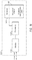
- FIG. 16 is a block diagram of a server, network device or equipment 1600 which may be used in some implementations of the present disclosure.
- Network equipment 1600 of FIG. 16 has components which may include one or more processors 1602 coupled to memory 1604 and to communication interface 1606.
- Interface 1606 is configured to connect to one or more networks for communications.
- the one or more processors 1602 of the network equipment are configured to operate in accordance with program instructions 1608 stored in memory 1604, in order to perform basic functions as well as techniques of the present disclosure, as described above in relation to the Figures.
- the program instructions may provide a NF, a VNF, or an NFV of the present disclosure.
- the techniques of the present disclosure may be embodied as a computer program product including a transitory or non-transitory computer readable medium and instructions (e.g. instructions provided as an NF, VNF, or NFV module) stored in the non-transitory computer readable medium, where the instructions are executable on one or more processors (for example processors of the server or network device) for performing/causing the carrying out of the steps of the technique.
- instructions e.g. instructions provided as an NF, VNF, or NFV module
- a control plane (CP) entity for mobility management may select a CP entity for session management for a session of a user equipment (UE) based on a first set of data items.
- the CP entity for mobility management may further select a user plane (UP) entity for the session of the UE based on a second set of data items, where second set of data items include at least some of the same data items of the first set.
- the CP entity for mobility management may send, to the selected CP entity for session management, a message including an identity or indication of the selected UP entity for the session of the UE.
- the selected CP entity for session management may choose the identified or indicated UP entity in the message for use in the session of the UE.
- the CP entity for mobility management may be an access and mobility management function (AMF) of a 5G mobile network, where the identity or indication of the selected UP entity is included in a data field for a data network name (DNN) of a create session request message.
- the CP entity for mobility management may be a mobility management entity (MME) of a 4G / LTE based mobile network, where the identity or indication of the selected UP entity is included in a data field for an access point name (APN) of a create session request message.
- MME mobility management entity
- a CP entity for session management may receive, from a CP entity for mobility management, a message which includes a create session request for creating a session for a UE.
- the CP entity for session management may identify from the message an identity or indication of a user plane (UP) entity.
- the CP entity for session management may select, for use in the session, a UP entity corresponding to or based on the identity or indication of the UP entity from the message.
- the CP entity for session management may send, to the selected UP entity, a message which includes a session establishment request for establishing the session.
- UP user plane
- the CP entity for session management may be a session management function (SMF) of a 5G mobile network, where the identity or indication of the selected UP entity is extracted from a data field for a data network name (DNN) of the create session request.
- the CP entity for mobility management may be a gateway (GW) control plane (CP) entity (GW-C) of a 4G / LTE based mobile network, where the identity or indication of the selected UP entity is extracted from a data field for an access point name (APN) of the create session request.
- GW gateway
- CP control plane
- API access point name
- Additional methods and apparatus of the present disclosure are for use in selecting / reselecting a UP entity and/or an IP address for a session for a UE, which may performed by a CP entity for session management (e.g. a GW-C or SMF).
- a CP entity for session management e.g. a GW-C or SMF.
- a message which includes a request for creating a session for a UE may be received, where the UE is being served by a first base station in a first cell.
- a first UP entity may be selected for the session based on a first cell identifier of the first base station.
- the selection may be performed with use of a mapping table which includes a plurality of cell identifiers mapped to a respective plurality of UP identifiers of UP entities.
- a message which includes a handover indication of a handover of the UE from the first base station to the second base station may be received.
- a message which includes a detach request including a reactivation request may be sent to the UE.
- the UE may respond to the message by detaching and reattaching to the network with a (new) request for creating a (new) session.
- a message which includes a request for creating a session for a UE may be received, where the UE is being served by the second base station in the second cell.
- a second UP entity may be selected for the session based on a second cell identifier of the second base station. The selection may be performed with use of a mapping table.
- a corresponding method of the UE may be performed for selecting / reselecting a UP entity and/or an IP address for a session for a UE.
- a first message may be received, where the first message includes a first cell identifier corresponding to a first base station serving a UE.
- a data session may be created for the UE, which includes selecting a first UP entity for carrying data traffic of the UE based on the first cell identifier. More particularly, the first UP entity for carrying the data traffic for the UE may be selected based on the first cell identifier with use of a mapping table which includes a plurality of cell identifiers mapped to a respective plurality of UP identifiers of UP entities.
- the mapping in the mapping table may be a geographic or location mapping, and configured such that each UP entity of a plurality of UP entities identified by the plurality of UP identifiers is located in proximity to (or in a region of) a corresponding base station of a plurality of base stations identified by the plurality of cell identifiers. Subsequently, a second message may be received, where the second message includes a second cell identifier corresponding to a second base station serving the UE. A new data session may be created for the UE, which includes selecting a second UP entity for carrying data traffic of the UE based on the second cell identifier.
- the second UP entity for carrying the data traffic for the UE may be selected based on the second cell identifier with use of the mapping table which includes the plurality of cell identifiers mapped to the respective plurality of UP identifiers of UP entities.
- the second UP entity may be a geographically-appropriate UP entity for the UE being newly served by the second base station.
- first means “first,” “second,” etc.
- these elements should not be limited by these terms. These terms are only used to distinguish one element from another.
- a first cell identifier could be termed a second cell identifier, and similarly, a second cell identifier could be termed a first cell identifier, without changing the meaning of the description, so long as all occurrences of the "first cell identifier" are renamed consistently and all occurrences of the second cell identifier are renamed consistently.
- the first cell identifier and the second cell identifier are both contacts, but they are not the same cell identifier.
- the term “if' may be construed to mean “when” or “upon” or “in response to determining” or “in accordance with a determination” or “in response to detecting,” that a stated condition precedent is true, depending on the context.
- the phrase “if it is determined [that a stated condition precedent is true]” or “if [a stated condition precedent is true]” or “when [a stated condition precedent is true]” may be construed to mean “upon determining” or “in response to determining” or “in accordance with a determination” or “upon detecting” or “in response to detecting” that the stated condition precedent is true, depending on the context.
Landscapes
- Engineering & Computer Science (AREA)
- Computer Networks & Wireless Communication (AREA)
- Signal Processing (AREA)
- Computer Security & Cryptography (AREA)
- Databases & Information Systems (AREA)
- Mobile Radio Communication Systems (AREA)
Claims (15)
- Verfahren, das von einer Steuerebenen- bzw. Control Plane, CP, -Einheit für Mobilitätsverwaltung durchgeführt wird und aufweist:Auswählen (408) einer CP-Einheit für Sitzungsverwaltung für eine Sitzung eines User Equipment, UE, basierend auf einem ersten Satz von Datenelementen;Auswählen (410) einer Benutzerebenen- bzw. User Plane, UP, - Einheit für die Sitzung des UE basierend auf einem zweiten Satz von Datenelementen, wobei der zweite Satz von Datenelementen wenigstens einige der gleichen Datenelemente des ersten Satzes aufweist; undSenden (412), an die ausgewählte CP-Einheit für Sitzungsverwaltung, einer Nachricht, die eine Identität oder Angabe der ausgewählten UP-Einheit für die Sitzung des UE aufweist, wobei das Senden der Nachricht an die ausgewählte CP-Einheit für Sitzungsverwaltung des Weiteren eines aufweist von:Senden einer Nachricht, die eine Sitzungsherstellungsanfrage aufweist, die die Identität oder Angabe der ausgewählten UP-Einheit in einem Datenfeld für einen Zugangspunktnamen bzw. Access Point Name, APN, oder einen Datennetzwerknamen, DNN, aufweist; oderSenden einer Nachricht, die eine Sitzungsherstellungsanfrage aufweist, die die Identität oder Angabe der ausgewählten UP-Einheit als Metadaten in einem Access Point Name, APN oder einem Datennetzwerknamen, DNN aufweist.
- Verfahren nach Anspruch 1, wobei die CP-Einheit für Mobilitätsverwaltung eine Zugangs- und Mobilitätsverwaltungs- bzw. Access and Mobility Management, AMF, -Einheit (112) aufweist, wobei die ausgewählte CP-Einheit für Sitzungsverwaltung eine ausgewählte Sitzungsverwaltungsfunktions- bzw. Session Management Function, SMF, - Instanz (120a) aufweist und die ausgewählte UP-Einheit eine ausgewählte Benutzerebenenfunktions- bzw. User Plane Function, UPF, -Instanz (122a) aufweist.
- Verfahren nach Anspruch 2, das des Weiteren aufweist:
Erhalten wenigstens einiger der Datenelemente der ersten und der zweiten Sätze von einer vereinheitlichten Datenverwaltungs- bzw. Unified Data Management, UDM, -Einheit (118), wobei das Verfahren optional des Weiteren aufweist:
Delegieren des Erhaltens der Datenelemente und der Auswahl der SMF-Instanz (120a) und der UPF-Instanz (122a) an eine Netzwerkrepositoryfunktion (202), NRF - Verfahren nach Anspruch 1, wobei die CP-Einheit für Mobilitätsverwaltung eine Mobilitätsverwaltungseinheit bzw. Mobility Management Entity, MME, aufweist.
- Verfahren nach einem der vorhergehenden Ansprüche, wobei die gleichen Datenelemente der ersten und der zweiten Sätze Abonnementdaten oder Richtliniendaten aufweisen, die zu dem UE zugehörig sind.
- Steuerebenen- bzw. Control Plane, CP, -Einheit für Mobilitätsverwaltung, die konfiguriert ist zum:Auswählen (408) einer CP-Einheit für Sitzungsverwaltung für eine Sitzung eines User Equipment, UE, basierend auf einem ersten Satz von Datenelementen;Auswählen (410) einer Benutzerebenen- bzw. User Plane, UP, - Einheit für die Sitzung des UE basierend auf einem zweiten Satz von Datenelementen, wobei der zweite Satz von Datenelementen wenigstens einige der gleichen Datenelemente des ersten Satzes aufweist; undSenden (412), an die ausgewählte CP-Einheit für Sitzungsverwaltung, einer Nachricht, die eine Identität oder Angabe der ausgewählten UP-Einheit für die Sitzung des UE aufweist, wobei die Nachricht, die eine Identität oder Angabe der ausgewählten UP-Einheit für die Sitzung des UE aufweist, eine Sitzungsherstellungsanfrage aufweist, die die Identität oder Angabe der ausgewählten UP-Einheit in einem Datenfeld für, oder als Metadaten in, einen/einem Zugangspunktnamen bzw. Access Point Name, APN, oder einen/einem Datennetzwerknamen, DNN, aufweist.
- CP-Einheit für Mobilitätsverwaltung nach Anspruch 6, die des Weiteren aufweist:wobei die CP-Einheit für Mobilitätsverwaltung eine Zugangs- und Mobilitätsverwaltungs- bzw. Access and Mobility Management, AMF, - Einheit (112) eines 5G Mobilfunknetzes aufweist;wobei die ausgewählte CP-Einheit für Sitzungsverwaltung eine Sitzungsverwaltungsfunktions- bzw. Session Management Function, SMF, - Einheit (120a) aufweist; undwobei die ausgewählte UP-Einheit eine Benutzerebenenfunktion bzw. User Plane Function, UPF (122a) aufweist.
- CP-Einheit für Mobilitätsverwaltung nach Anspruch 6, die des Weiteren aufweist:wobei die CP-Einheit für Mobilitätsverwaltung des Weiteren eine Mobilitätsverwaltungseinheit bzw. Mobility Management Entity, MME, eines auf Long Term Evolution, LTE, basierenden Mobilfunknetzes aufweist;wobei die ausgewählte CP-Einheit für Sitzungsverwaltung eine ausgewählte Gateway, GW, CP-Einheit, GW-C, aufweist; undwobei die ausgewählte UP-Einheit eine ausgewählte Gateway, GW, UP-Einheit, GW-U, aufweist.
- CP-Einheit für Mobilitätsverwaltung nach einem der Ansprüche 6 bis 8, wobei die gleichen Datenelemente der ersten und der zweiten Sätze Abonnementdaten oder Richtliniendaten aufweisen, die zu dem UE zugehörig sind.
- CP-Einheit für Mobilitätsverwaltung nach einem der Ansprüche 6 bis 9, die des Weiteren dazu konfiguriert ist zu veranlassen, dass wenigstens einige der Datenelemente der ersten und der zweiten Sätze von einer vereinheitlichten Datenverwaltungs- bzw. Unified Data Management, UDM, -Einheit (118) direkt oder durch eine Netzwerkrepositoryfunktion, NRF, (202) abgerufen werden.
- Verfahren, das von einer Steuerebenen- bzw. Control Plane, CP, -Einheit für Sitzungsverwaltung durchgeführt wird und aufweist:Empfangen (704), von einer CP-Einheit für Mobilitätsverwaltung, einer Nachricht, die eine Sitzungsherstellungsanfrage aufweist, wobei die Sitzungsherstellungsanfrage zum Herstellen einer Sitzung für ein User Equipment, UE, vorgesehen ist;Identifizieren (706) einer Identität oder Angabe einer Benutzerebenen- bzw. User Plane, UP, -Einheit von der Sitzungsherstellungsanfrage;Auswählen (708) einer UP-Einheit für die Sitzung entsprechend oder basierend auf der Identität oder Angabe in der Nachricht; undSenden (710) einer Nachricht an die ausgewählte UP-Einheit, die eine Sitzungsherstellungsanfrage aufweist, wobei das Identifizieren der Identität oder Angabe der UP-Einheit in der Nachricht des Weiteren aufweist:
Extrahieren, aus der Nachricht, der Identität oder Angabe der UP-Einheit aus einem Datenfeld für, oder Metadaten in, einen/einem Anwendungspunktnamen bzw. Application Point Name, APN, oder einem Datennetzwerknamen, DNN - Verfahren nach Anspruch 11, wobei die ausgewählte UP-Einheit verwendet wird, um Verkehr für die Sitzung des UE zu tragen.
- Verfahren nach Anspruch 11 oder 12, wobei das Auswählen der UP-Einheit für die Sitzung des UE durchgeführt wird durch Auswählen der UP-Einheit, die der Identität oder Angabe in der Nachricht entspricht.
- Steuerebenen- bzw. Control Plane, CP, -Einheit für Sitzungsverwaltung, die dazu konfiguriert ist, das Verfahren nach einem der Ansprüche 11 bis 13 durchzuführen.
- Computerlesbares Medium, das Befehle speichert, die, wenn sie von einem oder mehreren Prozessoren einer Steuerebenen- bzw. Control Plane, CP, - Einheit für Mobilitätsverwaltung oder einem oder mehreren Prozessoren einer CP-Einheit für Sitzungsverwaltung durchgeführt werden, veranlassen, dass die CP-Einheit für Mobilitätsverwaltung das Verfahren nach einem der Ansprüche 1 bis 5 durchführt, oder veranlassen, dass die CP-Einheit für Sitzungsverwaltung einen der Ansprüche 11 bis 13 durchführt.
Applications Claiming Priority (2)
| Application Number | Priority Date | Filing Date | Title |
|---|---|---|---|
| US15/894,498 US10764935B2 (en) | 2018-02-12 | 2018-02-12 | Methods and apparatus for selecting network slice, session management and user plane functions |
| PCT/US2019/016617 WO2019156962A1 (en) | 2018-02-12 | 2019-02-05 | Methods and apparatus for selecting network slice, session management and user plane functions |
Publications (2)
| Publication Number | Publication Date |
|---|---|
| EP3753303A1 EP3753303A1 (de) | 2020-12-23 |
| EP3753303B1 true EP3753303B1 (de) | 2022-12-07 |
Family
ID=65516774
Family Applications (1)
| Application Number | Title | Priority Date | Filing Date |
|---|---|---|---|
| EP19706838.0A Active EP3753303B1 (de) | 2018-02-12 | 2019-02-05 | Verfahren und vorrichtung zur auswahl von netzwerk-slices, sitzungsverwaltung und funktionen auf benutzerebene |
Country Status (3)
| Country | Link |
|---|---|
| US (2) | US10764935B2 (de) |
| EP (1) | EP3753303B1 (de) |
| WO (1) | WO2019156962A1 (de) |
Families Citing this family (23)
| Publication number | Priority date | Publication date | Assignee | Title |
|---|---|---|---|---|
| US11388098B2 (en) * | 2018-04-16 | 2022-07-12 | Telefonaktiebolaget Lm Ericsson (Publ) | Method of providing network slice packet flow descriptors to a session management function in a telecommunication network |
| US10700882B2 (en) * | 2018-07-31 | 2020-06-30 | T-Mobile Usa, Inc. | GX session recovery for policy and charging rules function |
| WO2020034911A1 (zh) | 2018-08-13 | 2020-02-20 | 华为技术有限公司 | 通信方法和通信装置 |
| CN110830268B (zh) * | 2018-08-13 | 2022-12-30 | 华为技术有限公司 | 通信方法和通信装置 |
| US10904827B2 (en) * | 2018-09-27 | 2021-01-26 | T-Mobile Usa, Inc. | User plane system selection based on latency |
| CN118283844A (zh) | 2018-11-14 | 2024-07-02 | 联想(新加坡)私人有限公司 | 与双注册的设备建立连接 |
| US10798635B2 (en) * | 2018-12-03 | 2020-10-06 | At&T Intellectual Property I, L.P. | Mobile edge computing for data network traffic |
| US11343653B2 (en) | 2019-01-15 | 2022-05-24 | Ofinno, Llc | Session establishment to join a group communication |
| US10848525B2 (en) * | 2019-01-29 | 2020-11-24 | Verizon Patent And Licensing Inc. | Systems and method for selection of a user plane component for internet protocol multimedia subsystem sessions |
| CN111083690B (zh) * | 2019-08-16 | 2024-08-02 | 中兴通讯股份有限公司 | 用户面功能实体信息的上报方法及装置 |
| CN110662165B (zh) * | 2019-10-09 | 2020-12-15 | 广州爱浦路网络技术有限公司 | 一种基于节点编号选择用户面功能upf的方法 |
| US11108636B2 (en) | 2019-10-23 | 2021-08-31 | Cisco Technology, Inc. | Integrity verification for managing network configurations |
| CN113067907B (zh) * | 2020-01-02 | 2023-04-07 | 中国移动通信有限公司研究院 | 一种边缘应用寻址的方法和相关设备 |
| US11356887B2 (en) * | 2020-02-24 | 2022-06-07 | Verizon Patent And Licensing Inc. | Systems and methods for selecting a core network slice for user plane communications |
| CN117044388A (zh) * | 2020-10-14 | 2023-11-10 | 欧芬诺有限责任公司 | 通信网络 |
| US11140618B1 (en) * | 2020-11-04 | 2021-10-05 | Sprint Communications Company L.P. | Wireless data service based on geographic data network names |
| CN112671571B (zh) * | 2020-12-16 | 2024-04-16 | 腾讯科技(深圳)有限公司 | 网络切片的选择方法、装置、设备及存储介质 |
| US11451954B1 (en) * | 2021-02-03 | 2022-09-20 | Sprint Communications Company L.P. | Wireless communication service delivery using multiple data network names (DNNs) |
| CN115708369A (zh) * | 2021-08-20 | 2023-02-21 | 华为技术有限公司 | 用于传输数据的方法和装置 |
| US12213095B2 (en) | 2021-11-17 | 2025-01-28 | Cisco Technology, Inc. | Slice resource management for reducing the negative impacts of slice quotas |
| CN116709337A (zh) * | 2022-02-28 | 2023-09-05 | 华为技术有限公司 | 通信方法与装置 |
| US20240284260A1 (en) * | 2023-02-17 | 2024-08-22 | T-Mobile Innovations Llc | Wireless network slice brokering |
| US12483978B2 (en) * | 2023-08-07 | 2025-11-25 | Verizon Patent And Licensing Inc. | Application identity based network slice enablement server |
Family Cites Families (39)
| Publication number | Priority date | Publication date | Assignee | Title |
|---|---|---|---|---|
| US8605662B2 (en) | 2007-07-20 | 2013-12-10 | Cisco Technology, Inc. | Intelligent real access point name (APN) selection using virtual APNS |
| GB0907213D0 (en) * | 2009-04-27 | 2009-06-10 | Sharp Kk | Relay apparatus and method |
| EP2517511A1 (de) | 2009-12-22 | 2012-10-31 | InterDigital Patent Holdings, Inc. | Gruppenbasierte maschine-zu-maschine-kommunikation |
| US8655996B2 (en) | 2010-06-30 | 2014-02-18 | At&T Intellectual Property I, L.P. | Customized behavior of a control layer towards an application server in a packet-based network |
| JP5728377B2 (ja) | 2011-12-20 | 2015-06-03 | 株式会社日立製作所 | 無線通信システムおよび無線通信方法、ならびに移動端末 |
| EP2848023A4 (de) * | 2012-05-07 | 2016-01-06 | Ericsson Telefon Ab L M | Kommunikationsvorrichtung und mobilitätsverfahren dafür |
| US9325581B2 (en) | 2013-04-02 | 2016-04-26 | International Business Machines Corporation | Context-aware management of applications at the edge of a network |
| US9642077B2 (en) | 2013-10-23 | 2017-05-02 | Cisco Technology, Inc. | Node selection in virtual evolved packet core |
| US9942909B2 (en) * | 2014-02-28 | 2018-04-10 | Futurewei Technologies, Inc. | System and method for connection rehoming |
| JP6469846B2 (ja) | 2014-05-12 | 2019-02-13 | ノキア ソリューションズ アンド ネットワークス ゲゼルシャフト ミット ベシュレンクテル ハフツング ウント コンパニー コマンディトゲゼルシャフト | 仮想化ネットワーク機能を含む通信ネットワークの制御法 |
| US9571405B2 (en) | 2015-02-25 | 2017-02-14 | Cisco Technology, Inc. | Metadata augmentation in a service function chain |
| US9769069B2 (en) | 2015-04-10 | 2017-09-19 | At&T Intellectual Property I, L.P. | Methods and apparatus to provide a consumer services cloud in a communications network |
| US20160353367A1 (en) | 2015-06-01 | 2016-12-01 | Huawei Technologies Co., Ltd. | System and Method for Virtualized Functions in Control and Data Planes |
| EP3326406B1 (de) | 2015-07-23 | 2020-05-27 | Nokia Solutions and Networks Oy | Beschleunigungsanlagensteuerung in einem netzwerk |
| US10644955B2 (en) | 2015-08-21 | 2020-05-05 | Huawei Technologies Co., Ltd. | Method and apparatus for network slicing |
| US10425830B2 (en) | 2015-09-07 | 2019-09-24 | Electronics And Telecommunications Research Institute | Mobile communication network system and method for composing network component configurations |
| EP3363222B1 (de) | 2015-10-15 | 2024-01-10 | Telefonaktiebolaget LM Ericsson (PUBL) | Vorrichtung und verfahren zur anhängung eines benutzergeräts an ein mobilkommunikationsnetzwerk |
| WO2017074486A1 (en) | 2015-10-28 | 2017-05-04 | Intel IP Corporation | Slice-based operation in wireless networks with end-to-end network slicing |
| US10129108B2 (en) | 2015-11-13 | 2018-11-13 | Huawei Technologies Co., Ltd. | System and methods for network management and orchestration for network slicing |
| US10064058B2 (en) | 2015-12-08 | 2018-08-28 | Cisco Technology, Inc. | Node selection using a combination of subscription entitlement and nodal characteristics |
| US10009751B2 (en) | 2015-12-28 | 2018-06-26 | Cisco Technology, Inc. | Virtual mobility anchor for network sharing |
| EP3398361B1 (de) | 2015-12-29 | 2020-05-13 | Telefonaktiebolaget LM Ericsson (PUBL) | Netzwerkknoten und darin ausgeführte verfahren zur ermöglichung der kommunikation in einem kommunikationsnetzwerk |
| CN108702803B (zh) * | 2016-01-21 | 2021-09-24 | Lg电子株式会社 | 在无线通信系统中在本地网络中发送/接收v2x消息的方法及其设备 |
| US10142994B2 (en) * | 2016-04-18 | 2018-11-27 | Electronics And Telecommunications Research Institute | Communication method and apparatus using network slicing |
| WO2017197273A1 (en) * | 2016-05-12 | 2017-11-16 | Convida Wireless, Llc | Connecting to virtualized mobile core networks |
| US9967801B2 (en) * | 2016-06-10 | 2018-05-08 | Lg Electronics Inc. | Method and apparatus for receiving authorization information on network slice |
| EP4142366A1 (de) | 2016-07-01 | 2023-03-01 | IDAC Holdings, Inc. | Verfahren zur unterstützung der sitzungskontinuität auf sitzungsbasis |
| US10972552B2 (en) * | 2016-09-30 | 2021-04-06 | Huawei Technologies Co., Ltd. | Method and system for user plane path selection |
| US11246172B2 (en) * | 2016-10-07 | 2022-02-08 | Lg Electronics Inc. | Method for selecting session and service continuity mode in wireless communication system and device therefor |
| US10749995B2 (en) | 2016-10-07 | 2020-08-18 | Cisco Technology, Inc. | System and method to facilitate integration of information-centric networking into internet protocol networks |
| US10764376B2 (en) | 2016-10-18 | 2020-09-01 | Cisco Technology, Inc. | System and method for node selection based on mid-session and end-session event information |
| JP2019534654A (ja) * | 2016-11-22 | 2019-11-28 | エルジー エレクトロニクス インコーポレイティド | Ranベースの通知領域を設定する方法及び装置 |
| JP6816251B2 (ja) * | 2016-11-27 | 2021-01-20 | エルジー エレクトロニクス インコーポレイティド | 無線通信システムにおける登録解除方法及びこのための装置 |
| US11523319B2 (en) * | 2017-01-09 | 2022-12-06 | Lg Electronics Inc. | Method for managing PDU session in wireless communication system and device for same |
| US10462840B2 (en) * | 2017-01-09 | 2019-10-29 | Huawei Technologies Co., Ltd. | System and methods for session management |
| WO2018137873A1 (en) | 2017-01-27 | 2018-08-02 | Telefonaktiebolaget Lm Ericsson (Publ) | Secondary authentication of a user equipment |
| US10736028B2 (en) * | 2017-03-20 | 2020-08-04 | Qualcomm Incorporated | Network service configuration and selection using network slices |
| US10616934B2 (en) * | 2017-12-08 | 2020-04-07 | Comcast Cable Communications, Llc | User plane function selection for isolated network slice |
| US10986602B2 (en) * | 2018-02-09 | 2021-04-20 | Intel Corporation | Technologies to authorize user equipment use of local area data network features and control the size of local area data network information in access and mobility management function |
-
2018
- 2018-02-12 US US15/894,498 patent/US10764935B2/en active Active
-
2019
- 2019-02-05 WO PCT/US2019/016617 patent/WO2019156962A1/en not_active Ceased
- 2019-02-05 EP EP19706838.0A patent/EP3753303B1/de active Active
-
2020
- 2020-05-27 US US16/884,820 patent/US11395354B2/en active Active
Also Published As
| Publication number | Publication date |
|---|---|
| EP3753303A1 (de) | 2020-12-23 |
| US11395354B2 (en) | 2022-07-19 |
| US20200288513A1 (en) | 2020-09-10 |
| US20190254083A1 (en) | 2019-08-15 |
| US10764935B2 (en) | 2020-09-01 |
| WO2019156962A1 (en) | 2019-08-15 |
Similar Documents
| Publication | Publication Date | Title |
|---|---|---|
| EP3753303B1 (de) | Verfahren und vorrichtung zur auswahl von netzwerk-slices, sitzungsverwaltung und funktionen auf benutzerebene | |
| US11729586B2 (en) | Methods and apparatus for establishing a group session in a mobile network for subscribers associated with a group | |
| EP3403448B1 (de) | Funknetzknoten, kommunikationsnetzwerk und damit durchgeführte verfahren | |
| EP3641424B1 (de) | Verfahren zur registrierung eines benutzergeräts in einer netzwerkscheibe in einem drahtlosen kommunikationssystem und benutzergerät dafür | |
| US10375628B2 (en) | Method in a network node of a wireless communications network | |
| US11070967B2 (en) | Network nodes and methods performed therein for enabling communication in a communication network | |
| JP6897985B2 (ja) | 専用コアネットワーク(dcn)選択 | |
| CN108605269B (zh) | 一种会话管理方法及装置 | |
| CN110461013B (zh) | 一种网元选择方法及装置 | |
| EP3592008A1 (de) | Verfahren und vorrichtung zur verwendung von ladn in drahtloskommunikationssystem | |
| WO2020060817A1 (en) | Methods and apparatus for selecting a serving gateway for a session of a user equipment (ue) in a mobile network having 5g non-standalone (nsa) architecture deployments | |
| EP3634080B1 (de) | Sitzungsverarbeitungsverfahren, -vorrichtung und -system | |
| KR20220093408A (ko) | 무선 연결을 재개하기 위한 사용자 단말 및 방법 | |
| WO2016082147A1 (zh) | 寻呼方法、基站及寻呼系统 | |
| CN113473564A (zh) | 网络切片切换的方法、建立pdu会话的方法及装置 | |
| WO2017029430A1 (en) | Method system and apparatus | |
| JP7132715B2 (ja) | UE(User Equipment) | |
| WO2013064065A1 (zh) | 应用数据处理方法及装置 | |
| WO2019139141A1 (ja) | ユーザ装置 |
Legal Events
| Date | Code | Title | Description |
|---|---|---|---|
| STAA | Information on the status of an ep patent application or granted ep patent |
Free format text: STATUS: UNKNOWN |
|
| STAA | Information on the status of an ep patent application or granted ep patent |
Free format text: STATUS: THE INTERNATIONAL PUBLICATION HAS BEEN MADE |
|
| PUAI | Public reference made under article 153(3) epc to a published international application that has entered the european phase |
Free format text: ORIGINAL CODE: 0009012 |
|
| STAA | Information on the status of an ep patent application or granted ep patent |
Free format text: STATUS: REQUEST FOR EXAMINATION WAS MADE |
|
| 17P | Request for examination filed |
Effective date: 20200907 |
|
| AK | Designated contracting states |
Kind code of ref document: A1 Designated state(s): AL AT BE BG CH CY CZ DE DK EE ES FI FR GB GR HR HU IE IS IT LI LT LU LV MC MK MT NL NO PL PT RO RS SE SI SK SM TR |
|
| AX | Request for extension of the european patent |
Extension state: BA ME |
|
| DAV | Request for validation of the european patent (deleted) | ||
| DAX | Request for extension of the european patent (deleted) | ||
| GRAP | Despatch of communication of intention to grant a patent |
Free format text: ORIGINAL CODE: EPIDOSNIGR1 |
|
| STAA | Information on the status of an ep patent application or granted ep patent |
Free format text: STATUS: GRANT OF PATENT IS INTENDED |
|
| INTG | Intention to grant announced |
Effective date: 20220708 |
|
| RAP3 | Party data changed (applicant data changed or rights of an application transferred) |
Owner name: CISCO TECHNOLOGY, INC. |
|
| RIN1 | Information on inventor provided before grant (corrected) |
Inventor name: ALEX, ARUN C. Inventor name: LA ROCHE, HUMBERTO JOSE Inventor name: DODD-NOBLE, AENEAS, SEAN Inventor name: STAMMERS, TIMOTHY PETER |
|
| GRAS | Grant fee paid |
Free format text: ORIGINAL CODE: EPIDOSNIGR3 |
|
| GRAA | (expected) grant |
Free format text: ORIGINAL CODE: 0009210 |
|
| STAA | Information on the status of an ep patent application or granted ep patent |
Free format text: STATUS: THE PATENT HAS BEEN GRANTED |
|
| AK | Designated contracting states |
Kind code of ref document: B1 Designated state(s): AL AT BE BG CH CY CZ DE DK EE ES FI FR GB GR HR HU IE IS IT LI LT LU LV MC MK MT NL NO PL PT RO RS SE SI SK SM TR |
|
| REG | Reference to a national code |
Ref country code: GB Ref legal event code: FG4D |
|
| REG | Reference to a national code |
Ref country code: CH Ref legal event code: EP Ref country code: AT Ref legal event code: REF Ref document number: 1537067 Country of ref document: AT Kind code of ref document: T Effective date: 20221215 |
|
| REG | Reference to a national code |
Ref country code: DE Ref legal event code: R096 Ref document number: 602019022847 Country of ref document: DE |
|
| REG | Reference to a national code |
Ref country code: IE Ref legal event code: FG4D |
|
| REG | Reference to a national code |
Ref country code: LT Ref legal event code: MG9D |
|
| REG | Reference to a national code |
Ref country code: NL Ref legal event code: MP Effective date: 20221207 |
|
| PG25 | Lapsed in a contracting state [announced via postgrant information from national office to epo] |
Ref country code: SE Free format text: LAPSE BECAUSE OF FAILURE TO SUBMIT A TRANSLATION OF THE DESCRIPTION OR TO PAY THE FEE WITHIN THE PRESCRIBED TIME-LIMIT Effective date: 20221207 Ref country code: NO Free format text: LAPSE BECAUSE OF FAILURE TO SUBMIT A TRANSLATION OF THE DESCRIPTION OR TO PAY THE FEE WITHIN THE PRESCRIBED TIME-LIMIT Effective date: 20230307 Ref country code: LT Free format text: LAPSE BECAUSE OF FAILURE TO SUBMIT A TRANSLATION OF THE DESCRIPTION OR TO PAY THE FEE WITHIN THE PRESCRIBED TIME-LIMIT Effective date: 20221207 Ref country code: FI Free format text: LAPSE BECAUSE OF FAILURE TO SUBMIT A TRANSLATION OF THE DESCRIPTION OR TO PAY THE FEE WITHIN THE PRESCRIBED TIME-LIMIT Effective date: 20221207 Ref country code: ES Free format text: LAPSE BECAUSE OF FAILURE TO SUBMIT A TRANSLATION OF THE DESCRIPTION OR TO PAY THE FEE WITHIN THE PRESCRIBED TIME-LIMIT Effective date: 20221207 |
|
| REG | Reference to a national code |
Ref country code: AT Ref legal event code: MK05 Ref document number: 1537067 Country of ref document: AT Kind code of ref document: T Effective date: 20221207 |
|
| PG25 | Lapsed in a contracting state [announced via postgrant information from national office to epo] |
Ref country code: RS Free format text: LAPSE BECAUSE OF FAILURE TO SUBMIT A TRANSLATION OF THE DESCRIPTION OR TO PAY THE FEE WITHIN THE PRESCRIBED TIME-LIMIT Effective date: 20221207 Ref country code: PL Free format text: LAPSE BECAUSE OF FAILURE TO SUBMIT A TRANSLATION OF THE DESCRIPTION OR TO PAY THE FEE WITHIN THE PRESCRIBED TIME-LIMIT Effective date: 20221207 Ref country code: LV Free format text: LAPSE BECAUSE OF FAILURE TO SUBMIT A TRANSLATION OF THE DESCRIPTION OR TO PAY THE FEE WITHIN THE PRESCRIBED TIME-LIMIT Effective date: 20221207 Ref country code: HR Free format text: LAPSE BECAUSE OF FAILURE TO SUBMIT A TRANSLATION OF THE DESCRIPTION OR TO PAY THE FEE WITHIN THE PRESCRIBED TIME-LIMIT Effective date: 20221207 Ref country code: GR Free format text: LAPSE BECAUSE OF FAILURE TO SUBMIT A TRANSLATION OF THE DESCRIPTION OR TO PAY THE FEE WITHIN THE PRESCRIBED TIME-LIMIT Effective date: 20230308 |
|
| PG25 | Lapsed in a contracting state [announced via postgrant information from national office to epo] |
Ref country code: NL Free format text: LAPSE BECAUSE OF FAILURE TO SUBMIT A TRANSLATION OF THE DESCRIPTION OR TO PAY THE FEE WITHIN THE PRESCRIBED TIME-LIMIT Effective date: 20221207 |
|
| P01 | Opt-out of the competence of the unified patent court (upc) registered |
Effective date: 20230525 |
|
| PG25 | Lapsed in a contracting state [announced via postgrant information from national office to epo] |
Ref country code: SM Free format text: LAPSE BECAUSE OF FAILURE TO SUBMIT A TRANSLATION OF THE DESCRIPTION OR TO PAY THE FEE WITHIN THE PRESCRIBED TIME-LIMIT Effective date: 20221207 Ref country code: RO Free format text: LAPSE BECAUSE OF FAILURE TO SUBMIT A TRANSLATION OF THE DESCRIPTION OR TO PAY THE FEE WITHIN THE PRESCRIBED TIME-LIMIT Effective date: 20221207 Ref country code: PT Free format text: LAPSE BECAUSE OF FAILURE TO SUBMIT A TRANSLATION OF THE DESCRIPTION OR TO PAY THE FEE WITHIN THE PRESCRIBED TIME-LIMIT Effective date: 20230410 Ref country code: EE Free format text: LAPSE BECAUSE OF FAILURE TO SUBMIT A TRANSLATION OF THE DESCRIPTION OR TO PAY THE FEE WITHIN THE PRESCRIBED TIME-LIMIT Effective date: 20221207 Ref country code: CZ Free format text: LAPSE BECAUSE OF FAILURE TO SUBMIT A TRANSLATION OF THE DESCRIPTION OR TO PAY THE FEE WITHIN THE PRESCRIBED TIME-LIMIT Effective date: 20221207 Ref country code: AT Free format text: LAPSE BECAUSE OF FAILURE TO SUBMIT A TRANSLATION OF THE DESCRIPTION OR TO PAY THE FEE WITHIN THE PRESCRIBED TIME-LIMIT Effective date: 20221207 |
|
| PG25 | Lapsed in a contracting state [announced via postgrant information from national office to epo] |
Ref country code: SK Free format text: LAPSE BECAUSE OF FAILURE TO SUBMIT A TRANSLATION OF THE DESCRIPTION OR TO PAY THE FEE WITHIN THE PRESCRIBED TIME-LIMIT Effective date: 20221207 Ref country code: IS Free format text: LAPSE BECAUSE OF FAILURE TO SUBMIT A TRANSLATION OF THE DESCRIPTION OR TO PAY THE FEE WITHIN THE PRESCRIBED TIME-LIMIT Effective date: 20230407 Ref country code: AL Free format text: LAPSE BECAUSE OF FAILURE TO SUBMIT A TRANSLATION OF THE DESCRIPTION OR TO PAY THE FEE WITHIN THE PRESCRIBED TIME-LIMIT Effective date: 20221207 |
|
| REG | Reference to a national code |
Ref country code: DE Ref legal event code: R097 Ref document number: 602019022847 Country of ref document: DE |
|
| PG25 | Lapsed in a contracting state [announced via postgrant information from national office to epo] |
Ref country code: MC Free format text: LAPSE BECAUSE OF FAILURE TO SUBMIT A TRANSLATION OF THE DESCRIPTION OR TO PAY THE FEE WITHIN THE PRESCRIBED TIME-LIMIT Effective date: 20221207 |
|
| REG | Reference to a national code |
Ref country code: CH Ref legal event code: PL |
|
| PLBE | No opposition filed within time limit |
Free format text: ORIGINAL CODE: 0009261 |
|
| STAA | Information on the status of an ep patent application or granted ep patent |
Free format text: STATUS: NO OPPOSITION FILED WITHIN TIME LIMIT |
|
| REG | Reference to a national code |
Ref country code: BE Ref legal event code: MM Effective date: 20230228 |
|
| PG25 | Lapsed in a contracting state [announced via postgrant information from national office to epo] |
Ref country code: LU Free format text: LAPSE BECAUSE OF NON-PAYMENT OF DUE FEES Effective date: 20230205 Ref country code: LI Free format text: LAPSE BECAUSE OF NON-PAYMENT OF DUE FEES Effective date: 20230228 Ref country code: DK Free format text: LAPSE BECAUSE OF FAILURE TO SUBMIT A TRANSLATION OF THE DESCRIPTION OR TO PAY THE FEE WITHIN THE PRESCRIBED TIME-LIMIT Effective date: 20221207 Ref country code: CH Free format text: LAPSE BECAUSE OF NON-PAYMENT OF DUE FEES Effective date: 20230228 |
|
| 26N | No opposition filed |
Effective date: 20230908 |
|
| PG25 | Lapsed in a contracting state [announced via postgrant information from national office to epo] |
Ref country code: SI Free format text: LAPSE BECAUSE OF FAILURE TO SUBMIT A TRANSLATION OF THE DESCRIPTION OR TO PAY THE FEE WITHIN THE PRESCRIBED TIME-LIMIT Effective date: 20221207 |
|
| REG | Reference to a national code |
Ref country code: IE Ref legal event code: MM4A |
|
| PG25 | Lapsed in a contracting state [announced via postgrant information from national office to epo] |
Ref country code: IE Free format text: LAPSE BECAUSE OF NON-PAYMENT OF DUE FEES Effective date: 20230205 |
|
| PG25 | Lapsed in a contracting state [announced via postgrant information from national office to epo] |
Ref country code: BE Free format text: LAPSE BECAUSE OF NON-PAYMENT OF DUE FEES Effective date: 20230228 |
|
| PG25 | Lapsed in a contracting state [announced via postgrant information from national office to epo] |
Ref country code: IT Free format text: LAPSE BECAUSE OF FAILURE TO SUBMIT A TRANSLATION OF THE DESCRIPTION OR TO PAY THE FEE WITHIN THE PRESCRIBED TIME-LIMIT Effective date: 20221207 |
|
| PG25 | Lapsed in a contracting state [announced via postgrant information from national office to epo] |
Ref country code: BG Free format text: LAPSE BECAUSE OF FAILURE TO SUBMIT A TRANSLATION OF THE DESCRIPTION OR TO PAY THE FEE WITHIN THE PRESCRIBED TIME-LIMIT Effective date: 20221207 |
|
| PG25 | Lapsed in a contracting state [announced via postgrant information from national office to epo] |
Ref country code: BG Free format text: LAPSE BECAUSE OF FAILURE TO SUBMIT A TRANSLATION OF THE DESCRIPTION OR TO PAY THE FEE WITHIN THE PRESCRIBED TIME-LIMIT Effective date: 20221207 |
|
| PGFP | Annual fee paid to national office [announced via postgrant information from national office to epo] |
Ref country code: DE Payment date: 20250123 Year of fee payment: 7 |
|
| PGFP | Annual fee paid to national office [announced via postgrant information from national office to epo] |
Ref country code: FR Payment date: 20250213 Year of fee payment: 7 |
|
| PGFP | Annual fee paid to national office [announced via postgrant information from national office to epo] |
Ref country code: GB Payment date: 20250212 Year of fee payment: 7 |
|
| PG25 | Lapsed in a contracting state [announced via postgrant information from national office to epo] |
Ref country code: CY Free format text: LAPSE BECAUSE OF FAILURE TO SUBMIT A TRANSLATION OF THE DESCRIPTION OR TO PAY THE FEE WITHIN THE PRESCRIBED TIME-LIMIT; INVALID AB INITIO Effective date: 20190205 |
|
| PG25 | Lapsed in a contracting state [announced via postgrant information from national office to epo] |
Ref country code: HU Free format text: LAPSE BECAUSE OF FAILURE TO SUBMIT A TRANSLATION OF THE DESCRIPTION OR TO PAY THE FEE WITHIN THE PRESCRIBED TIME-LIMIT; INVALID AB INITIO Effective date: 20190205 |