EP3753263B1 - Audio encoding device and method - Google Patents
Audio encoding device and method Download PDFInfo
- Publication number
- EP3753263B1 EP3753263B1 EP18711541.5A EP18711541A EP3753263B1 EP 3753263 B1 EP3753263 B1 EP 3753263B1 EP 18711541 A EP18711541 A EP 18711541A EP 3753263 B1 EP3753263 B1 EP 3753263B1
- Authority
- EP
- European Patent Office
- Prior art keywords
- direct sound
- signals
- format
- audio
- diffuse
- Prior art date
- Legal status (The legal status is an assumption and is not a legal conclusion. Google has not performed a legal analysis and makes no representation as to the accuracy of the status listed.)
- Active
Links
Images




Classifications
-
- H—ELECTRICITY
- H04—ELECTRIC COMMUNICATION TECHNIQUE
- H04R—LOUDSPEAKERS, MICROPHONES, GRAMOPHONE PICK-UPS OR LIKE ACOUSTIC ELECTROMECHANICAL TRANSDUCERS; ELECTRIC HEARING AIDS; PUBLIC ADDRESS SYSTEMS
- H04R1/00—Details of transducers, loudspeakers or microphones
- H04R1/20—Arrangements for obtaining desired frequency or directional characteristics
- H04R1/32—Arrangements for obtaining desired frequency or directional characteristics for obtaining desired directional characteristic only
- H04R1/40—Arrangements for obtaining desired frequency or directional characteristics for obtaining desired directional characteristic only by combining a number of identical transducers
- H04R1/406—Arrangements for obtaining desired frequency or directional characteristics for obtaining desired directional characteristic only by combining a number of identical transducers microphones
-
- G—PHYSICS
- G10—MUSICAL INSTRUMENTS; ACOUSTICS
- G10L—SPEECH ANALYSIS TECHNIQUES OR SPEECH SYNTHESIS; SPEECH RECOGNITION; SPEECH OR VOICE PROCESSING TECHNIQUES; SPEECH OR AUDIO CODING OR DECODING
- G10L19/00—Speech or audio signals analysis-synthesis techniques for redundancy reduction, e.g. in vocoders; Coding or decoding of speech or audio signals, using source filter models or psychoacoustic analysis
- G10L19/008—Multichannel audio signal coding or decoding using interchannel correlation to reduce redundancy, e.g. joint-stereo, intensity-coding or matrixing
-
- G—PHYSICS
- G10—MUSICAL INSTRUMENTS; ACOUSTICS
- G10L—SPEECH ANALYSIS TECHNIQUES OR SPEECH SYNTHESIS; SPEECH RECOGNITION; SPEECH OR VOICE PROCESSING TECHNIQUES; SPEECH OR AUDIO CODING OR DECODING
- G10L19/00—Speech or audio signals analysis-synthesis techniques for redundancy reduction, e.g. in vocoders; Coding or decoding of speech or audio signals, using source filter models or psychoacoustic analysis
- G10L19/02—Speech or audio signals analysis-synthesis techniques for redundancy reduction, e.g. in vocoders; Coding or decoding of speech or audio signals, using source filter models or psychoacoustic analysis using spectral analysis, e.g. transform vocoders or subband vocoders
-
- H—ELECTRICITY
- H04—ELECTRIC COMMUNICATION TECHNIQUE
- H04R—LOUDSPEAKERS, MICROPHONES, GRAMOPHONE PICK-UPS OR LIKE ACOUSTIC ELECTROMECHANICAL TRANSDUCERS; ELECTRIC HEARING AIDS; PUBLIC ADDRESS SYSTEMS
- H04R3/00—Circuits for transducers
- H04R3/02—Circuits for transducers for preventing acoustic reaction, i.e. acoustic oscillatory feedback
-
- H—ELECTRICITY
- H04—ELECTRIC COMMUNICATION TECHNIQUE
- H04S—STEREOPHONIC SYSTEMS
- H04S3/00—Systems employing more than two channels, e.g. quadraphonic
- H04S3/02—Systems employing more than two channels, e.g. quadraphonic of the matrix type, i.e. in which input signals are combined algebraically, e.g. after having been phase shifted with respect to each other
-
- H—ELECTRICITY
- H04—ELECTRIC COMMUNICATION TECHNIQUE
- H04R—LOUDSPEAKERS, MICROPHONES, GRAMOPHONE PICK-UPS OR LIKE ACOUSTIC ELECTROMECHANICAL TRANSDUCERS; ELECTRIC HEARING AIDS; PUBLIC ADDRESS SYSTEMS
- H04R2430/00—Signal processing covered by H04R, not provided for in its groups
- H04R2430/20—Processing of the output signals of the acoustic transducers of an array for obtaining a desired directivity characteristic
- H04R2430/21—Direction finding using differential microphone array [DMA]
-
- H—ELECTRICITY
- H04—ELECTRIC COMMUNICATION TECHNIQUE
- H04S—STEREOPHONIC SYSTEMS
- H04S2400/00—Details of stereophonic systems covered by H04S but not provided for in its groups
- H04S2400/15—Aspects of sound capture and related signal processing for recording or reproduction
-
- H—ELECTRICITY
- H04—ELECTRIC COMMUNICATION TECHNIQUE
- H04S—STEREOPHONIC SYSTEMS
- H04S2420/00—Techniques used stereophonic systems covered by H04S but not provided for in its groups
- H04S2420/11—Application of ambisonics in stereophonic audio systems
Definitions
- the present invention is related to audio recording and encoding, in particular for virtual reality applications, especially for virtual reality provided by a small portable device.
- VR virtual reality
- Ambisonic B-format with expensive directive microphones.
- Professional audio microphones exist to either record A-format to be encoded into Ambisonic B-format or directly Ambisonic B-format, for instance using Soundfield microphones. More generally speaking, it is technically difficult to arrange omnidirectional microphones on a mobile device to capture sound for VR.
- a way to generate Ambisonic B-format signals, given a distribution of omnidirectional microphones, is based on differential microphone arrays, i.e. applying delay and adding beam-forming in order to derive first order virtual microphone (e.g. cardioids) signals as A-format.
- first order virtual microphone e.g. cardioids
- the first limitation of this technique results from its spatial aliasing which, by design, reduces the bandwidth to frequencies ⁇ in the range: ⁇ ⁇ c 4 d mic , where c stands for the sound celerity and d mic the distance between a pair of two omnidirectional microphones.
- a second weakness results, for higher order Ambisonic B-format, from the microphone requirement. The required number of microphones and their required positions are not anymore suitable for mobile devices.
- Another way of generating ambisonic B-format signals from omnidirectional microphones corresponds to sampling the sound field at the recording point in space using a sufficiently dense distribution of microphones. These sampled sound pressure signals are then converted to spherical harmonics and can be linearly combined to eventually generate B-format signals.
- SNR signal to noise ratio
- Directional Audio Coding is also a further method for spatial sound representation, but it does not generate B-format signals. Instead, it reads first order B-format signals and generates a number of related audio parameters (direction of arrival, diffuseness) and adds these to an omnidirectional audio channel. Later, the decoder takes the above information and converts it to a multi-channel audio signal using amplitude panning for direct sound and de-correlating for diffuse sound.
- DirAc is thus a different technique which takes B-format as input to render it to its own audio format.
- the document EP 1 737 271 A1 shows an array microphone for recording spatial audio.
- an audio encoding device for encoding N audio signals, from N microphones, where N ⁇ 3, is provided.
- the device comprises a delay estimator, configured to estimate angles of incidence of direct sound by estimating for each pair of the N audio signals an angle of incidence of direct sound, and a beam deriver, configured to derive A-format direct sound signals from the estimated angles of incidence by deriving from each estimated angle of incidence an A-format direct sound signal, each A-format direct sound signal being a first-order virtual microphone signal, especially a cardioids signal. This allows for determining the A-format direct sound signals with a low hardware effort.
- the device additionally comprises an encoder, configured to encode the A-format direct sound signals in first-order ambisonic B-format direct sound signals by applying a transformation matrix to the A-format direct sound signals. This allows for generating ambisonic B-format signals using only a very low number of microphones, but still achieving a high output sound quality.
- the audio encoding device moreover comprises a short time Fourier transformer, configured to perform a short time Fourier transformation on each of the N audio signals x 1 , x 2 , x 3 , resulting in N short time Fourier transformed audio signals X 1 [k,i], X 2 [k,i], X 3 [k,i].
- the device comprises a direction of arrival estimator, configured to estimate a direction of arrival from the first-order ambisonic B-format direct sound signals, and a higher order ambisonic encoder, configured to encode higher order ambisonic B-format direct sound signals, using the first-order ambisonic B-format direct sound signals and the estimated direction of arrival, wherein higher order ambisonic B-format direct sound signals have an order higher than one.
- a direction of arrival estimator configured to estimate a direction of arrival from the first-order ambisonic B-format direct sound signals
- a higher order ambisonic encoder configured to encode higher order ambisonic B-format direct sound signals, using the first-order ambisonic B-format direct sound signals and the estimated direction of arrival, wherein higher order ambisonic B-format direct sound signals have an order higher than one.
- the higher order ambisonic B-format direct sound signals comprise second order ambisonic B-format direct sound signals limited to two dimensions
- the audio encoding device comprises a microphone matcher, configured to perform a matching of the N frequency domain audio signals, resulting in N matched frequency domain audio signals. This allows for further quality increase of the output signals.
- the audio encoding device comprises a diffuse sound estimator, configured to estimate a diffuse sound power, and a de-correlation filter bank, configured to perform a de-correlation of the diffuse sound power by generating three orthogonal diffuse sound components from the diffuse sound estimate power. This allows for implementing diffuse sound into the output signals.
- the audio encoding device comprises an adder, configured to add channel-wise, the first-order ambisonic B-format direct sound signals and the higher order ambisonic B-format direct sound signals, and/or the diffuse sound signals, resulting in complete ambisonic B-format signals.
- an adder configured to add channel-wise, the first-order ambisonic B-format direct sound signals and the higher order ambisonic B-format direct sound signals, and/or the diffuse sound signals, resulting in complete ambisonic B-format signals.
- an audio recording device comprising N microphones configured to record the N audio signals and an audio encoding device according to the first aspect or any of the implementation forms of the first aspect is provided. This allows for an audio recording and encoding in a single device.
- a method for encoding N audio signals, from N microphones, where N ⁇ 3 comprises estimating angles of incidence of direct sound by estimating for each pair of the N audio signals an angle of incidence of direct sound, and deriving A-format direct sound signals from the estimated angles of incidence by deriving from each estimated angle of incidence an A-format direct sound signal, each A-format direct sound signal being a first-order virtual microphone signal. This allows for determining the A-format direct sound signals with a low hardware effort.
- the method additionally comprises encoding the ambisonic A-format direct sound signals in first-order ambisonic B-format direct sound signals by applying at least one transformation matrix to the A-format direct sound signals. This allows for a simple and efficient determining of the ambisonic B-format direct sound signals.
- the method may further comprise extracting higher order ambisonic B-format direct sound signals by extracting direction of arrival from first order ambisonic B-format direct sound signals.
- a computer program with a program code for performing the method according to the third aspect is provided.
- the proposed approach is based on at least three omnidirectional microphones on a mobile device. Successively it estimates the angles of incidence of direct sound by means of delay estimation between the different microphone pairs. Given the incidences of direct sound, it derives beam signals, called the direct sound A-format signals. The direct sound A-format signals are then encoded into first order B-format using relevant transformation matrix.
- a direction of arrival estimate is derived from the X and Y first order B-format signals.
- the diffuse, non-directive sound is optionally rendered as multiple orthogonal components, generated using de-correlation filters.
- FIG. 1 we demonstrate the construction and general function of an embodiment of the first aspect and second aspect of the invention along FIG. 1 .
- FIG. 2-FIG. 9 further details of the construction and function of the first embodiment and the second embodiment are shown.
- FIG. 10 finally the function of an embodiment of the third aspect of the invention is described in detail. Similar entities and reference numbers in different figures have been partially omitted.
- FIG. 1 a first embodiment of the audio encoding device 3 is shown. Moreover, a first embodiment of the audio recording device 1 according to the second aspect of the invention is shown.
- the audio recording device 1 comprises a number of N ⁇ 3 microphones 2, which are connected to the audio encoding device 3.
- the audio encoding device 3 comprises a delay estimator 11, which is connected to the microphones 2.
- the audio encoding device 3 moreover comprises a beam deriver 12, which is connected to the delay estimator.
- the audio encoding device 3 comprises an encoder 13, which is connected to the beam deriver 12. Note that the encoder 13 is an optional feature with regard to the first aspect of the invention.
- the microphones 2 record N ⁇ 3 audio signals. These audio signals are preprocessed by components integrated into the microphones 2, in this diagram. For example, a transformation into the frequency domain is performed. This will be shown in more detail along FIG. 2 .
- the preprocessed audio signals are handed to the delay estimator 11, which estimates angles of incidence of direct sound by estimating for each pair of the N audio signals and angle of incidence of direct sound. These angles of incidence of direct sound are handed to the beam deriver 12, which derives A-format direct sound signals therefrom.
- Each A-format direct sound signal is a first-order virtual microphone signal, especially a cardioid signal.
- the encoder 13 which encodes the A-format direct sound signals to first-order ambisonic B-format direct sound signals by applying a transformation matrix to the A-format direct sound signals.
- the encoder outputs the first-order ambisonic B-format direct sound signals.
- FIG. 2 a second embodiment of the audio encoding device 3 and the audio recording device 1 are shown.
- the individual microphones 2a, 2b, 2c which correspond to the microphones 2 of FIG. 1 , are shown.
- Each of the microphones 2a, 2b, 2c is connected to a short-time Fourier transformer 10a, 10b, 10c, which each performs a short-time Fourier transformation of the N audio signals resulting in N short-time Fourier transformed audio signals.
- the beam deriver 12 determines the A-format direct sound signals and hands them to the encoder 13, which performs the encoding to B-format direct sound signals.
- the audio encoding device 3 moreover comprises a direction-of-arrival estimator 20, which is connected to the encoder 13. Moreover, it comprises a higher order ambisonic encoder 21, which is connected to the direction-of-arrival estimator 20.
- the direction-of-arrival estimator 20 estimates a direction of arrival from the first-order ambisonic B-format direct sound signals and hands it to the higher order ambisonic encoder 21.
- the higher order ambisonic encoder 21 encodes higher order ambisonic B-format direct sound signals, using the first-order ambisonic B-format direct sound signals and the estimated direction of arrival as an input.
- the higher order ambisonic B-format direct sound signals have a higher order than 1.
- the audio encoding device 3 comprises a microphone matcher 30, which performs a matching of the N frequency domain audio signals output by the short-time Fourier transformers 10a, 10b, 10c resulting in N match frequency domain audio signals.
- the audio encoding device 3 moreover comprises a diffuse sound estimator 31, which is configured to estimate a diffuse sound power based upon the N match frequency domain audio signals.
- the audio encoding device 3 comprises a de-correlation filter bank 32, which is connected to the diffuse sound estimator 31 and configured to perform a de-correlation of the diffuse sound power by generating three orthogonal diffuse sound components from the diffuse sound estimate power.
- the audio encoding device 3 comprises an adder 40, which adds the first-order B-format direct sound signals provided by the encoder 13, the higher order ambisonic B-format signals provided by the higher order encoder 21 and the diffuse sound components provided by the de-correlation filter bank 32.
- the sum signal is handed to an inverse short-time Fourier transformer 41, which performs an inverse short-time Fourier transformation to achieve the final ambisonic B-format signals in the time domain.
- FIG. 3 - 9 further details regarding the function of the individual components, shown in FIG. 2 are described.
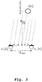
- FIG. 3 an angle of incidence, as it is determined by the delay estimator 11 is shown.
- FIG. 4 an example of an audio recording device 1 is shown in a two-dimensional diagram.
- the three microphones 2a, 2b, 2c are depicted in their actual physical location.
- the following algorithm aims at estimating the angle of incidence of direct sound based on cross-correlation between both recorded microphone signals x 1 and x 2 and derive parametrically gain filters to generate beams focusing in specific directions.
- a phase estimation, between both recording microphones, is carried out at each time-frequency tile.
- the microphone time-frequency representations, X 1 and X 2 of the microphone signals, are obtained using a N STFT points short-time Fourier transform (STFT).
- STFT short-time Fourier transform
- a microphone array has a restriction on the minimum spatial sampling rate.
- a high frequency extension is proposed based in equation (8) to constraint an unwrapping algorithm.
- the unwrapping aims at correcting the phase angle ⁇ 12 [ k , i ] by adding a multiple l [ k , i ] of 2 ⁇ when absolute jump between the two consecutive elements,
- the estimated unwrapped phase ⁇ 12 is obtained by limiting the multiples l to their physical possible values. Eventually, even if the phase is aliased at high-frequency, its slope still follows the same principles as the delay estimation at low frequency.
- the derived delay relates directly to the angle of incidence of sound emitted by a sound source, as illustrated in Figure 2 .
- a virtual cardioid signal can be retrieved from the direct sound of the input microphone signals. This corresponds to the function of the beam estimator 12.
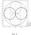
- FIG. 5 three cardioid signals based upon three microphone pairs are depicted in a two-dimensional diagram, showing the respective gains.
- These spherical harmonics form a set of orthogonal basis functions and can be used to describe any function on the surface of a sphere.
- three, the minimum number of, microphones are considered and placed in the horizontal XY -plane, for instance disposed at the edges of a mobile device as illustrated in Figure 3 , having the coordinates ( x m 1 , y m 1 ), ( x m 2 , y m 2 ) , and ( x m 3 , y m 3 ).
- the three possible unordered microphone pairs are defined as:
- v p 1 x m 1 y m 1 ⁇ x m 2 y m 2
- v p 2 x m 2 y m 2 ⁇ x m 3 y m 3
- v p 3 x m 3 y m 3 ⁇ x m 1 y m 1 .
- the three resulting cardioids are pointing in the three directions ⁇ p 1 , ⁇ p 2 , and ⁇ p 3 , defining the corresponding A-format representation, as illustrated in Figure 4 .
- the corresponding first order Ambisonic B-format signals can be computed by means of linear combination of the spectra A p n .
- the first order Ambisonic B-format normalized directional responses R W , R X , and R Y are shown in Figure 5 , where R W corresponds to a monopole. while the signals R X and R Y correspond to two orthogonal dipoles.
- the directional responses are thus derived by substituting the azimuth angle ⁇ by the estimated DOA ⁇ XY . For instance, considering second order (assuming no elevation, i.e.
- the resulting ambisonic channels, R R , R U , R V , R L , R M , R P , and R Q contain only the direct sound components of the sound field.
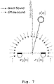
- FIG. 7 the occurrence of direct sound from a sound source and omnidirectional diffuse sound is shown in a diagram depicting the locations of two microphones.
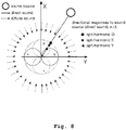
- FIG. 8 the directional responses to a sound source of direct sound is shown. Additionally, omnidirectional diffuse sound is depicted.
- the Ambisonic B-format signals are obtained by projecting the sound field unto the spherical harmonics basis defined in the previous table.
- the projection corresponds to the integration of the sound field signal over the spherical harmonics.
- the single diffuse sound estimate (28) is equivalent for all three microphones (or all three microphone pairs). Therefore there is no possibility to retrieve the native diffuse sound components of the Ambisonic B-format signals, i.e. D W , D X , and D Y as they would be obtained separately by projection of the diffuse sound field unto the spherical harmonics basis.
- an alternative is to generate three orthogonal diffuse sound components from the single known diffuse sound estimate P diff . This way, even if the diffuse sound components do not correspond to the native Ambisonic B-format obtained by projection, the most perceptually important property of orthogonality (enabling localization and spatialization) is preserved. This can be achieved by using de-correlation filters.
- the de-correlation filters are derived from a Gaussian noise sequence u of given length l u .
- a Gram-Schmidt process applied to this sequence leads to N u orthogonal sequences U 1 , U 2 , ⁇ , U N u which serve as filters to generate N u orthogonal diffuse sounds.
- N u 3
- the de-correlation filters are shaped such that they have an exponential decay over time, similarly as reverberation is a room.
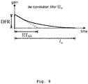
- FIG. 9 the filter response of a filter of the de-correlation filter bank 32 of FIG. 2 is shown. Especially the time constant of such a filter is depicted.
- the exponential decay of the de-correlation filters illustrated in Fig. 9 , will directly have an influence on the diffuse sound components in the B-format signals. A long decay will over emphasize the diffuse sound contribution in the final B-format but will ensure better separation between the three diffuse sound components.
- the resulting de-correlation filters are modulated by the diffuse-field responses of the ambisonic B-format channels they correspond to.
- This addition is performed by the adder 40 of FIG. 2 .
- a first optional step 100 at least 3 audio signals are recorded.
- angles of incidence of direct sound are estimated, by estimating for each pair of the N audio signals an angle of incidence of direct sound.
- A-format direct sound signals are derived from the estimated angles of incidence, by deriving from each estimated angle of incidence an A-format direct sound signal, each A-format direct sound signal being a first-order virtual microphone signal.
- the ambisonic A-format direct sound signals are encoded to first-order ambisonic B-format direct sound signals by applying at least one transformation matrix to the A-format direct sound signals.
- the fourth step of performing the encoding is an optional step with regard to the third aspect of the invention.
- a further optional fifth step 104 a higher order ambisonic B-Format signal is generated based on direction of arrival derived from first order B-Format.
- the audio encoding device according to the first aspect of the invention as well as the audio recording device according to the second aspect of the invention relate very closely to the audio encoding method according to the third aspect of the invention. Therefore, the elaborations along FIG. 1 - 9 are also valid with regard to the audio encoding method shown in FIG. 10 .
- the invention is not limited to the examples and especially not to a specific number of microphones.
- the characteristics of the exemplary embodiments can be used in any advantageous combination.
Landscapes
- Engineering & Computer Science (AREA)
- Physics & Mathematics (AREA)
- Health & Medical Sciences (AREA)
- Acoustics & Sound (AREA)
- Signal Processing (AREA)
- Otolaryngology (AREA)
- Audiology, Speech & Language Pathology (AREA)
- Human Computer Interaction (AREA)
- Multimedia (AREA)
- Computational Linguistics (AREA)
- Mathematical Physics (AREA)
- Spectroscopy & Molecular Physics (AREA)
- General Health & Medical Sciences (AREA)
- Algebra (AREA)
- Mathematical Optimization (AREA)
- Pure & Applied Mathematics (AREA)
- Theoretical Computer Science (AREA)
- Mathematical Analysis (AREA)
- General Physics & Mathematics (AREA)
- Circuit For Audible Band Transducer (AREA)
Description
- The present invention is related to audio recording and encoding, in particular for virtual reality applications, especially for virtual reality provided by a small portable device.
- Virtual reality (VR) sound recording typically requires Ambisonic B-format with expensive directive microphones. Professional audio microphones exist to either record A-format to be encoded into Ambisonic B-format or directly Ambisonic B-format, for instance using Soundfield microphones. More generally speaking, it is technically difficult to arrange omnidirectional microphones on a mobile device to capture sound for VR.
- A way to generate Ambisonic B-format signals, given a distribution of omnidirectional microphones, is based on differential microphone arrays, i.e. applying delay and adding beam-forming in order to derive first order virtual microphone (e.g. cardioids) signals as A-format.
- The first limitation of this technique results from its spatial aliasing which, by design, reduces the bandwidth to frequencies ƒ in the range:

- Another way of generating ambisonic B-format signals from omnidirectional microphones corresponds to sampling the sound field at the recording point in space using a sufficiently dense distribution of microphones. These sampled sound pressure signals are then converted to spherical harmonics and can be linearly combined to eventually generate B-format signals.
- The main limitation of such approaches is the required number of microphones. For consumer applications, with only few microphones (commonly up to 6), linear processing is too limited leading to signal to noise ratio (SNR) issues at low frequencies, and aliasing at high frequencies.
- Directional Audio Coding (DirAc) is also a further method for spatial sound representation, but it does not generate B-format signals. Instead, it reads first order B-format signals and generates a number of related audio parameters (direction of arrival, diffuseness) and adds these to an omnidirectional audio channel. Later, the decoder takes the above information and converts it to a multi-channel audio signal using amplitude panning for direct sound and de-correlating for diffuse sound.
- DirAc is thus a different technique which takes B-format as input to render it to its own audio format.
- The
document EP 1 737 271 A1 shows an array microphone for recording spatial audio. - The document Farina Angelo et al.: "Spatial PCM sampling: a new method for sound recording and playback", XP040633139 deals with recording and reproducing spatial audio.
- The document Benjamin et al.: "A sound field microphone using tangential capsules", XP040567210 deals with recording spatial audio.
- The present invention is defined by the independent claims. Embodiments labelled as inventive embodiments in the following, which are not covered by the scope of protection defined by the independent claims, are to be understood as examples helpful for understanding the invention, but not as embodiments of the invention.
- Therefore, a need arises to provide an audio encoding device and method, which allow for generating ambisonic B-format sound signals while requiring only a low number of microphones and achieving a high output sound quality.
- This object is solved by the features of
claim 1 for the apparatus and claim 14 for the associated method. Further, it is solved by the features of claim 15 for the associated computer program. The dependent claims contain further developments. - According to a first aspect of the invention, an audio encoding device, for encoding N audio signals, from N microphones, where N ≥ 3, is provided. The device comprises a delay estimator, configured to estimate angles of incidence of direct sound by estimating for each pair of the N audio signals an angle of incidence of direct sound, and a beam deriver, configured to derive A-format direct sound signals from the estimated angles of incidence by deriving from each estimated angle of incidence an A-format direct sound signal, each A-format direct sound signal being a first-order virtual microphone signal, especially a cardioids signal. This allows for determining the A-format direct sound signals with a low hardware effort.
- According to an implementation form of the first aspect, the device additionally comprises an encoder, configured to encode the A-format direct sound signals in first-order ambisonic B-format direct sound signals by applying a transformation matrix to the A-format direct sound signals. This allows for generating ambisonic B-format signals using only a very low number of microphones, but still achieving a high output sound quality.
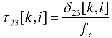
- According to an implementation form of the first aspect, N=3. The audio encoding device moreover comprises a short time Fourier transformer, configured to perform a short time Fourier transformation on each of the N audio signals x1, x2, x3, resulting in N short time Fourier transformed audio signals X1[k,i], X2[k,i], X3[k,i]. The delay estimator is then configured to determine cross spectra of each pair of short time Fourier transformed audio signals according to




- x1 is a first audio signal of the N audio signals,
- x2 is a second audio signal of the N audio signals,
- x3 is a third audio signal of the N audio signals,
- X1 is a first short time Fourier transformed audio signal,
- X2 is a second short time Fourier transformed audio signal,
- X3 is a third short time Fourier transformed audio signal,
- k is a frame of the short time Fourier transformed audio signal, and
- i is a frequency bin of the short time Fourier transformed audio signal,
- X12 is a cross spectrum of a pair of X1 and X2,
- X13 is a cross spectrum of a pair of X1 and X3,
- X23 is a cross spectrum of a pair of X2 and X3,
- αx is a forgetting factor,
- X∗ is the conjugate complex of X,
- j is the imaginary unit,
- Ψ̃ 12 is an angle of the complex cross spectrum of X12,
- Ψ̃ 13 is an angle of the complex cross spectrum of X13,
- Ψ̃ 23 is an angle of the complex cross spectrum of X23,
- ialias is a frequency bin corresponding to an aliasing frequency,
- fs is a sampling frequency,
- dmic is a distance of the microphones, and
- c is the speed of sound. This allows for a simple and efficient determining of the delays.
- According to a further implementation form of the first aspect, the beam deriver is configured to determine cardioid directional responses according to


derive the A-format direct sound signals according to


- D is a cardioid directional response, and
- A is an A-format direct sound signal. This allows for a simple and efficient determining of the beam signals.
- According to a further implementation form of the first aspect, the encoder is configured to encode the A-format direct sound signals to the first-order ambisonic B-format direct sound signals according to

- Rw is a first, zero-order ambisonic B-format direct sound signal,
- Rx is a first, first-order ambisonic B-format direct sound signal,
- Ry is a second, first-order ambisonic B-format direct sound signal, and
- Γ-1 is the transformation matrix. This allows for a simple and efficient determining of the beam signals.
- According to a further implementation form of the first aspect, the device comprises a direction of arrival estimator, configured to estimate a direction of arrival from the first-order ambisonic B-format direct sound signals, and a higher order ambisonic encoder, configured to encode higher order ambisonic B-format direct sound signals, using the first-order ambisonic B-format direct sound signals and the estimated direction of arrival, wherein higher order ambisonic B-format direct sound signals have an order higher than one. Thereby, an efficient encoding of the ambisonic B-format direct sound signal is achieved.
- According to a further implementation form of the first aspect, the direction of arrival estimator is configured to estimate the direction of arrival according to

θXY [k,i] is a direction of arrival of a direct sound of frame k and frequency bin i. This allows for a simple and efficient determining of the directions of arrival. - According to a further implementation form of the first aspect, the higher order ambisonic B-format direct sound signals comprise second order ambisonic B-format direct sound signals limited to two dimensions, wherein the higher order ambisonic encoder is configured to encode the second order ambisonic B-format direct sound signals according to


- RR is a first, second-order ambisonic B-format direct sound signal,
- RS is a second, second-order ambisonic B-format direct sound signal,
- RT is a third, second-order ambisonic B-format direct sound signal,
- RU is a fourth, second-order ambisonic B-format direct sound signal,
- RV is a fifth, second-order ambisonic B-format direct sound signal,
- denotes "defined as",

- φ is an elevation angle, and
- θ is an azimuth angle. This allows for an efficient encoding of the higher order ambisonic B-format signals.
- According to a further implementation form of the first aspect, the audio encoding device comprises a microphone matcher, configured to perform a matching of the N frequency domain audio signals, resulting in N matched frequency domain audio signals. This allows for further quality increase of the output signals.
- According to a further implementation form of the first aspect, the audio encoding device comprises a diffuse sound estimator, configured to estimate a diffuse sound power, and a de-correlation filter bank, configured to perform a de-correlation of the diffuse sound power by generating three orthogonal diffuse sound components from the diffuse sound estimate power. This allows for implementing diffuse sound into the output signals.
- According to a further implementation form of the first aspect, the diffuse sound estimator is configured to estimate the diffuse sound power according to


- Pdiff is the diffuse sound power,
- E { } is an expectation value,
-

- N1 is diffuse sound in a first channel, and
- N2 is diffuse sound in a second channel. This allows for an especially efficient estimation of the diffuse sound power.
- According to a further implementation form of the first aspect, the de-correlation filter bank is configured to perform the de-correlation of the diffuse sound power by generating three orthogonal diffuse sound components from the diffuse sound estimate power





- wherein D̃W [k,i] is a first channel diffuse sound component,
- wherein D̃X [k,i] is second channel diffuse sound component,
- wherein D̃Y [k,i] is third channel diffuse sound component,
- DFRW is a diffuse-field response of the first channel,
- DFRX is a diffuse-field response of the second channel,
- DFRY is a diffuse-field response of the third channel,
- wu is an exponential window,
- RT 60 is a reverberation time,
- U 1, U 2, U3 is the de-correlation filter bank,
- u is Gaussian noise sequence,
- lu is a given length of the Gaussian noise sequence, and
- P 2D-diff is the diffuse noise power. Thereby, an efficient de-correlation of the diffuse sound power is calculated.
- According to a further implementation form of the first aspect, the audio encoding device comprises an adder, configured to add channel-wise, the first-order ambisonic B-format direct sound signals and the higher order ambisonic B-format direct sound signals, and/or the diffuse sound signals, resulting in complete ambisonic B-format signals. Thereby, in a simple manner, a finished output signal is generated.
- According to a second aspect of the invention, an audio recording device comprising N microphones configured to record the N audio signals and an audio encoding device according to the first aspect or any of the implementation forms of the first aspect is provided. This allows for an audio recording and encoding in a single device.
- According to a third aspect of the invention, a method for encoding N audio signals, from N microphones, where N ≥ 3 is provided. The method comprises estimating angles of incidence of direct sound by estimating for each pair of the N audio signals an angle of incidence of direct sound, and deriving A-format direct sound signals from the estimated angles of incidence by deriving from each estimated angle of incidence an A-format direct sound signal, each A-format direct sound signal being a first-order virtual microphone signal. This allows for determining the A-format direct sound signals with a low hardware effort.
- According to an implementation form of the third aspect, the method additionally comprises encoding the ambisonic A-format direct sound signals in first-order ambisonic B-format direct sound signals by applying at least one transformation matrix to the A-format direct sound signals. This allows for a simple and efficient determining of the ambisonic B-format direct sound signals.
- The method may further comprise extracting higher order ambisonic B-format direct sound signals by extracting direction of arrival from first order ambisonic B-format direct sound signals.
- According to a fourth aspect of the invention, a computer program with a program code for performing the method according to the third aspect is provided.
- Especially, a method is proposed for parametric encoding of multiple omnidirectional microphone signals into any order Ambisonic B-format by means of:
- robust estimation of the angle of incidence of sound, based on microphone pair beam signals
- and de-correlation of diffuse sound
- The proposed approach is based on at least three omnidirectional microphones on a mobile device. Successively it estimates the angles of incidence of direct sound by means of delay estimation between the different microphone pairs. Given the incidences of direct sound, it derives beam signals, called the direct sound A-format signals. The direct sound A-format signals are then encoded into first order B-format using relevant transformation matrix.
- For optional higher order B-format, a direction of arrival estimate is derived from the X and Y first order B-format signals. The diffuse, non-directive sound is optionally rendered as multiple orthogonal components, generated using de-correlation filters.
- Generally, it has to be noted that all arrangements, devices, elements, units and means and so forth described in the present application could be implemented by software or hardware elements or any kind of combination thereof. Furthermore, the devices may be processors or may comprise processors, wherein the functions of the elements, units and means described in the present applications may be implemented in one or more processors. All steps which are performed by the various entities described in the present application as well as the functionality described to be performed by the various entities are intended to mean that the respective entity is adapted to or configured to perform the respective steps and functionalities. Even if in the following description or specific embodiments, a specific functionality or step to be performed by a general entity is not reflected in the description of a specific detailed element of that entity which performs that specific step or functionality, it should be clear for a skilled person that these methods and functionalities can be implemented in respect of software or hardware elements, or any kind of combination thereof.
- The present invention is in the following explained in detail in relation to embodiments of the invention in reference to the enclosed drawings, in which
- FIG. 1
- shows a first embodiment of the audio encoding device according to the first aspect of the invention and the audio recording device according to the second aspect of the invention;
- FIG. 2
- shows a second embodiment of the audio encoding device according to the first aspect of the invention and the audio recording device according to the second aspect of the invention;
- FIG. 3
- shows a pair of microphones in a diagram depicting the determining of an angle of incidence of a sound event;
- FIG. 4
- shows a third embodiment of the audio recording device according to the second aspect of the invention;
- FIG. 5
- shows A-format direct sound signals in a two-dimensional diagram;
- FIG. 6
- shows B-format direct sound signals in a two-dimensional diagram;
- FIG. 7
- shows diffuse sound received by two microphones;
- FIG. 8
- shows direct sound and diffuse sound in a two-dimensional diagram.
- FIG. 9
- shows an example of a de-correlation filter, as used by an audio encoding device according to a fourth embodiment of the first aspect;
- FIG. 10
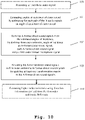
- shows an embodiment of the third aspect of the invention in a flow diagram.
- First, we demonstrate the construction and general function of an embodiment of the first aspect and second aspect of the invention along
FIG. 1 . With regard toFIG. 2-FIG. 9 , further details of the construction and function of the first embodiment and the second embodiment are shown. With regard toFIG. 10 , finally the function of an embodiment of the third aspect of the invention is described in detail. Similar entities and reference numbers in different figures have been partially omitted. - In
FIG. 1 , a first embodiment of theaudio encoding device 3 is shown. Moreover, a first embodiment of theaudio recording device 1 according to the second aspect of the invention is shown. - The
audio recording device 1 comprises a number of N ≥ 3microphones 2, which are connected to theaudio encoding device 3. Theaudio encoding device 3 comprises adelay estimator 11, which is connected to themicrophones 2. Theaudio encoding device 3 moreover comprises abeam deriver 12, which is connected to the delay estimator. Furthermore, theaudio encoding device 3 comprises anencoder 13, which is connected to thebeam deriver 12. Note that theencoder 13 is an optional feature with regard to the first aspect of the invention. - In order to determine ambisonic B-format direct sound signals, the
microphones 2 record N ≥ 3 audio signals. These audio signals are preprocessed by components integrated into themicrophones 2, in this diagram. For example, a transformation into the frequency domain is performed. This will be shown in more detail alongFIG. 2 . The preprocessed audio signals are handed to thedelay estimator 11, which estimates angles of incidence of direct sound by estimating for each pair of the N audio signals and angle of incidence of direct sound. These angles of incidence of direct sound are handed to thebeam deriver 12, which derives A-format direct sound signals therefrom. Each A-format direct sound signal is a first-order virtual microphone signal, especially a cardioid signal. These signals are handed on to theencoder 13, which encodes the A-format direct sound signals to first-order ambisonic B-format direct sound signals by applying a transformation matrix to the A-format direct sound signals. The encoder outputs the first-order ambisonic B-format direct sound signals. - In
FIG. 2 , a second embodiment of theaudio encoding device 3 and theaudio recording device 1 are shown. Here, theindividual microphones microphones 2 ofFIG. 1 , are shown. Each of themicrophones time Fourier transformer delay estimator 11, which performs the delay estimation and hands the angles of incidence to thebeam deriver 12. Thebeam deriver 12 determines the A-format direct sound signals and hands them to theencoder 13, which performs the encoding to B-format direct sound signals. InFIG. 2 , further components of theaudio encoding device 3 are shown. Here, theaudio encoding device 3 moreover comprises a direction-of-arrival estimator 20, which is connected to theencoder 13. Moreover, it comprises a higher orderambisonic encoder 21, which is connected to the direction-of-arrival estimator 20. - The direction-of-
arrival estimator 20 estimates a direction of arrival from the first-order ambisonic B-format direct sound signals and hands it to the higher orderambisonic encoder 21. The higher orderambisonic encoder 21 encodes higher order ambisonic B-format direct sound signals, using the first-order ambisonic B-format direct sound signals and the estimated direction of arrival as an input. The higher order ambisonic B-format direct sound signals have a higher order than 1. - Moreover, the
audio encoding device 3 comprises amicrophone matcher 30, which performs a matching of the N frequency domain audio signals output by the short-time Fourier transformers microphone matcher 30, theaudio encoding device 3 moreover comprises a diffusesound estimator 31, which is configured to estimate a diffuse sound power based upon the N match frequency domain audio signals. Furthermore, theaudio encoding device 3 comprises ade-correlation filter bank 32, which is connected to the diffusesound estimator 31 and configured to perform a de-correlation of the diffuse sound power by generating three orthogonal diffuse sound components from the diffuse sound estimate power. - Finally, the
audio encoding device 3 comprises anadder 40, which adds the first-order B-format direct sound signals provided by theencoder 13, the higher order ambisonic B-format signals provided by thehigher order encoder 21 and the diffuse sound components provided by thede-correlation filter bank 32. The sum signal is handed to an inverse short-time Fourier transformer 41, which performs an inverse short-time Fourier transformation to achieve the final ambisonic B-format signals in the time domain. - In the following, along
FIG. 3 - 9 , further details regarding the function of the individual components, shown inFIG. 2 are described. - In
FIG. 3 , an angle of incidence, as it is determined by thedelay estimator 11 is shown. - Especially, the propagation of direct sound following a ray from a sound source to a pair of microphones in the free-field is considered in
Fig. 3 . - In
FIG. 4 , an example of anaudio recording device 1 is shown in a two-dimensional diagram. The threemicrophones - The following algorithm aims at estimating the angle of incidence of direct sound based on cross-correlation between both recorded microphone signals x 1 and x 2 and derive parametrically gain filters to generate beams focusing in specific directions.
- A phase estimation, between both recording microphones, is carried out at each time-frequency tile. The microphone time-frequency representations, X 1 and X 2 , of the microphone signals, are obtained using a NSTFT points short-time Fourier transform (STFT). The delay relation between the two microphones can be derived from the cross-spectrum



- Unfortunately, analogous to the Nyquist frequency in temporal sampling, a microphone array has a restriction on the minimum spatial sampling rate. Using two microphones, the smallest wavelength of interest is given by


- Since the maximum travelling time between the two microphones of the array is given by dmic / c , the bounds of integer l is defined by

- A high frequency extension is proposed based in equation (8) to constraint an unwrapping algorithm. The unwrapping aims at correcting the phase angle Ψ̃ 12[k,i] by adding a multiple l[k,i] of 2π when absolute jump between the two consecutive elements, |Ψ̃ 12[k,i] - Ψ̃ 12[k,i-1]|, are greater than or equal to the jump tolerance of π. The estimated unwrapped phase Ψ 12 is obtained by limiting the multiples l to their physical possible values. Eventually, even if the phase is aliased at high-frequency, its slope still follows the same principles as the delay estimation at low frequency. For the purpose of delay estimation, it is then sufficient to integrate the unwrapped phase Ψ 12 over a number of frequency bins in order to derive its slope for later delay

- For each frequency bin i, dividing by the corresponding physical frequency, the delay δ 12[k,i], expressed in number of samples, is obtained from the previously derived phase


- The derived delay relates directly to the angle of incidence of sound emitted by a sound source, as illustrated in
Figure 2 . Given the travelling time delay between both microphones, the resulting angle of incidence θ 12[k,i] is
- In free-field, for direct sound, the directional response of a cardioid microphone pointing on the side of the array, is built as a function of the estimated angle of incidence

- By applying the gain D to the input spectrum X 1, a virtual cardioid signal can be retrieved from the direct sound of the input microphone signals. This corresponds to the function of the
beam estimator 12. - In
FIG. 5 , three cardioid signals based upon three microphone pairs are depicted in a two-dimensional diagram, showing the respective gains. - In
FIG. 6 , the gains of B-format ambisonic direct sound signals are shown in a two-dimensional diagram. - In the following, the conversion from A-format direct sound signals to B-format direct sound signals is shown. This corresponds to the function of the
encoder 13. - In the following Table are listed the Ambisonic B-format channels and their spherical representation D( θ , φ ) up to third-order, normalized with the Schmidt semi-normalization (SN3D), where θ and φ are, respectively, the azimuth and elevation angles:
Order Channel SN3D Definition: D(θ,φ) = 0 W 1 1 X cos θ cos φ Y sin θ cos φ Z sin φ 2 R (3sin2 φ-1)/2 S 
T 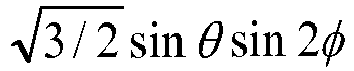
U 
V 
3 K sinφ(5sin2 φ-3)/2 L 
M 
N 
O 
P 
Q 
- These spherical harmonics form a set of orthogonal basis functions and can be used to describe any function on the surface of a sphere.
- Without loss of generality, three, the minimum number of, microphones are considered and placed in the horizontal XY-plane, for instance disposed at the edges of a mobile device as illustrated in
Figure 3 , having the coordinates (x m1 , y m1 ), (x m2 , y m2 ) , and (x m3 , y m3 ). - The three possible unordered microphone pairs are defined as:
-
pair 1 Δ= mic2 → mic1 -
pair 2 Δ= mic3 → mic2 -
pair 3 Δ= mic1 → mic3 - The look direction (Θ=0) being defined by the X-axis, their direction vectors are:


- The direction for each of the pair in the horizontal plane are

- And the microphone spacing:

- The gain (13) resulting from the angle of incidence estimation is applied to each pair leading to cardioid directional responses

- The three resulting cardioids are pointing in the three directions θ p
1 , θ p2 , and θ p3 , defining the corresponding A-format representation, as illustrated inFigure 4 . - Assuming that the obtained cardioids are coincident, the corresponding first order Ambisonic B-format signals can be computed by means of linear combination of the spectra Ap
n . The conversion from Ambisonic B-format to A-format is implemented as
- The inverse matrix of (18) enables to convert the cardioids to Ambisonic B-format,

- The first order Ambisonic B-format normalized directional responses R W, R X, and R Y , are shown in
Figure 5 , where R W corresponds to a monopole. while the signals R X and R Y correspond to two orthogonal dipoles. - In the following, the determining of higher order ambisonic B-format signals is shown. This corresponds to the function of the direction-of-
arrival estimator 20 and the higher orderambisonic encoder 21. - Deriving previously, the first order ambisonic B-format signals RW , RX , and RY for the direct sound, no explicit direction of arrival (DOA) of sound was computed. Instead the directional responses of the three signals RW , RX , and RY have been obtained from the A-format cardioid signals Ap
n in (17). - In order to obtain the higher order (e.g. second and third) ambisonic B-format signals, an explicit DOA is derived based on the two first order ambisonic B-format signals R X and R Y as:

- Again, assuming three omnidirectional microphones in the horizontal plane (ϕ=0), the channels of interest as defined in the ambisonic definition in the Table are limited to:
- order 0: W
- order 1: X, Y
- order 2: R, U, V
- order 3: L, M, P, Q
- The other channels are null since they are modulated by sinϕ, with ϕ=0. For each of the above listed channels the directional responses are thus derived by substituting the azimuth angle Θ by the estimated DOA ΘXY. For instance, considering second order (assuming no elevation, i.e. ϕ=0):

- The resulting ambisonic channels, RR , RU , RV , RL , RM , RP , and RQ , contain only the direct sound components of the sound field.
- Now, the handling of diffuse sound is shown. This corresponds to the diffuse
sound estimator 31 and thede-correlation filter bank 32 ofFIG. 2 . - In
FIG. 7 , the occurrence of direct sound from a sound source and omnidirectional diffuse sound is shown in a diagram depicting the locations of two microphones. - In
FIG. 8 , the directional responses to a sound source of direct sound is shown. Additionally, omnidirectional diffuse sound is depicted. - The previous derivation of the ambisonic B-format signals is only valid under the assumption of direct sound. It does not hold for diffuse sound. In the following a method for obtaining an equivalent diffuse sound for Ambisonic B-format signals is given. Considering enough time after the direct sound and a number of early reflections, numerous reflections are themselves reflected in the space creating a diffuse sound field. By diffuse sound field is mathematically understood as independent sounds having the same energy and coming from all directions, as illustrated in
Fig. 7 . - It is assumed that X 1 and X 2 can be modelled as


- It is reasonable to assume that the amount of diffuse sound in both microphone signals is the same, i.e.


- Eventually (23) can be re-written as

- Elimination of E{SS ∗} and a in (25) yields the quadratic equation


- The power estimate of diffuse sound, denoted Pdiff , is then one of the two solutions of (26), the physically possible one (the other solution of (26), yielding a diffuse sound power larger than the microphone signal power, is discarded, as it is physically impossible), i.e.

- Note that straightforwardly the contribution of the direct sound can be computed as

- This corresponds to the function of the diffuse
sound estimator 31. - By definition the Ambisonic B-format signals are obtained by projecting the sound field unto the spherical harmonics basis defined in the previous table. Mathematically, the projection corresponds to the integration of the sound field signal over the spherical harmonics.
- As illustrated in
FIG. 7 , due to the orthogonality property of the spherical harmonics basis: projecting mathematically independent sounds from all directions unto this basis will result in three orthogonal components:
- Note that this property does not hold anymore for direct sound, since a sound source emitting from only one direction projected unto the same basis will result in a single gain equal to the directional responses at the incidence angle of the sound source, leading to non-orthogonal, or in other terms, correlated components RW , RX , and RY .
- However, here, considering a distribution of three omnidirectional microphones, the single diffuse sound estimate (28) is equivalent for all three microphones (or all three microphone pairs). Therefore there is no possibility to retrieve the native diffuse sound components of the Ambisonic B-format signals, i.e. DW , DX , and DY as they would be obtained separately by projection of the diffuse sound field unto the spherical harmonics basis.
- Instead of getting the exact diffuse sound Ambisonic B-format signals, an alternative is to generate three orthogonal diffuse sound components from the single known diffuse sound estimate Pdiff . This way, even if the diffuse sound components do not correspond to the native Ambisonic B-format obtained by projection, the most perceptually important property of orthogonality (enabling localization and spatialization) is preserved. This can be achieved by using de-correlation filters.
- The de-correlation filters are derived from a Gaussian noise sequence u of given length lu . A Gram-Schmidt process applied to this sequence leads to Nu orthogonal sequences U 1,U 2,Λ ,UN
u which serve as filters to generate Nu orthogonal diffuse sounds. In the three microphones case described previously (Nu = 3):
Given the length lu of the noise Gaussian noise sequence u, the de-correlation filters are shaped such that they have an exponential decay over time, similarly as reverberation is a room. To do so, the sequences U 1,U 2,Λ ,UNu are multiplied with an exponential window w u with a time constant corresponding to the reverberation time RT 60 :
- In
FIG. 9 , the filter response of a filter of thede-correlation filter bank 32 ofFIG. 2 is shown. Especially the time constant of such a filter is depicted. - The exponential decay of the de-correlation filters, illustrated in
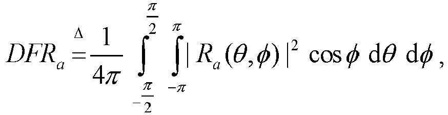
Fig. 9 , will directly have an influence on the diffuse sound components in the B-format signals. A long decay will over emphasize the diffuse sound contribution in the final B-format but will ensure better separation between the three diffuse sound components. - Eventually, the resulting de-correlation filters are modulated by the diffuse-field responses of the ambisonic B-format channels they correspond to. This way the amount of diffuse sound in each ambisonic B-format channel matches the amount of diffuse sound of a natural B-format recording. The diffuse-field response DFR is the average of the corresponding spherical harmonic directional-response-squared contributions considering all directions, i.e.

- In the three microphones case (Nu =3), the resulting de-correlations filters are

- This way, the orthogonality property between all three diffuse sounds being preserved any further processing using the generated B-format will work on diffuse sound too, i.e using conventional ambisonic decoding.
- Eventually both direct and diffuse sound contributions have to be mixed together in order to generate the full Ambisonic B-format. Given the assumed signal model, the direct and diffuse sounds are, by definition, orthogonal, too. Thus the complete Ambisonic B-format signal are obtained using a straightforward addition:

- This addition is performed by the
adder 40 ofFIG. 2 . - After this addition, only the inverse short-time Fourier transformation by the inverse short-
time Fourier transformer 41 is performed in order to achieve the output B-format ambisonic signals. - Finally, in
FIG. 10 , an embodiment of the audio encoding method according to the third aspect of the invention is shown. In a firstoptional step 100 at least 3 audio signals are recorded. In asecond step 101, angles of incidence of direct sound are estimated, by estimating for each pair of the N audio signals an angle of incidence of direct sound. In athird step 102, A-format direct sound signals are derived from the estimated angles of incidence, by deriving from each estimated angle of incidence an A-format direct sound signal, each A-format direct sound signal being a first-order virtual microphone signal. In afourth step 103, the ambisonic A-format direct sound signals are encoded to first-order ambisonic B-format direct sound signals by applying at least one transformation matrix to the A-format direct sound signals. Note that the fourth step of performing the encoding is an optional step with regard to the third aspect of the invention. In a further optionalfifth step 104, a higher order ambisonic B-Format signal is generated based on direction of arrival derived from first order B-Format. - Note that the audio encoding device according to the first aspect of the invention as well as the audio recording device according to the second aspect of the invention relate very closely to the audio encoding method according to the third aspect of the invention. Therefore, the elaborations along
FIG. 1 - 9 are also valid with regard to the audio encoding method shown inFIG. 10 . - These encoded signals are fully compatible with conventional Ambisonic B-format signals, and thus, can be used as input for Ambisonic B-format decoding or any other processing. The same principle can be applied to retrieve full higher order Ambisonic B-format signals with both direct and diffuse sounds contributions.
Abbreviations and Notations Abbreviation Definition VR Virtual Reality DirAc Directional Audio Coding DOA Direction Of Arrival STFT short-Time Fourier Transform SN3D Schmidt semi-Normalization 3D DFR Diffuse-Field Response SNR Signal to Noise Ratio HOA High Order Ambisonic Notation Definition x 1 , x 2 Both recorded microphone signals X 1[k,i] STFT of x 1 in frame k and frequency bin i S[k,i] STFT of source signal N1 [k,i] Diffuse noise in microphone 1 αX Forgeting factor TX averaging time-constant X 12[k,i] cross-spectrum two microphone signal 1 and 2 fs sampling frequency falias Frequency aliasing dmic Distance between both microphones E{ } Expectation oparator θ and φ azimuth and elevation angles Pdiff power estimate of diffuse noise RW , RX , RY First order Ambisonic components RR ,RU ,RV ,RL ,RM ,RP , and RQ Higher order Ambisonic components P 2D-diff power estimate of diffuse noise in 2D U 1,U 2,Λ ,UN u Orthogonal sequences Ψ̃ 12 Angle of the complex cross-spectrum X 12 Ψ12 The mean of unwrapped phase Ψ 12 over frequency aliasing l[i] An uncertainty integer which depends on frequency i L[i] Upper bound function for l[i] which depends on frequency i D(θ,φ) Spherical representation of the Ambisonic channels A p 1 , A p2 , A p3 ,..., Apn The cardioids that each of them generated with pair of microphones RT 60 Reverberation time lu Length of Gaussian noise sequence u wu Exponential window DFRW , DFRX , DFRY Diffuse-Field Responses for W,X,Y components - The invention is not limited to the examples and especially not to a specific number of microphones. The characteristics of the exemplary embodiments can be used in any advantageous combination.
- The invention has been described in conjunction with various embodiments herein. However, other variations to the disclosed embodiments can be understood and effected by those skilled in the art in practicing the claimed invention, from a study of the drawings, the disclosure and the appended claims. In the claims, the word "comprising " does not exclude other elements or steps and the indefinite article "a" or "an" does not exclude a plurality. A single processor or other unit may fulfill the functions of several items recited in the claims. The mere fact that certain measures are recited in usually different dependent claims does not indicate that a combination of these measures cannot be used to advantage. A computer program may be stored/distributed on a suitable medium, such as an optical storage medium or a solid-state medium supplied together with or as part of other hardware, but may also be distributed in other forms, such as via the internet or other wired or wireless communication systems.
Claims (15)
- An audio encoding device (3), for encoding N audio signals, from N microphones where N ≥ 3, the audio encoding device (3) comprising:- a delay estimator (11), configured to estimate angles of incidence of direct sound by estimating for each pair of the N audio signals an angle of incidence of direct sound,- a beam deriver (12), configured to derive A-format direct sound signals from the estimated angles of incidence by deriving from each estimated angle of incidence an A-format direct sound signal, each A-format direct sound signal being a first-order virtual microphone signal, and- an encoder (13), configured to encode the A-format direct sound signals in first-order ambisonic B-format direct sound signals by applying a transformation matrix to the A-format direct sound signals.
- The audio encoding device (3) according to claim 1,wherein N=3 and wherein the audio encoding device (3) comprises a short time Fourier transformer (10a, 10b, 10c), configured to perform a short time Fourier transformation on each of the N audio signals x1, x2, x3, resulting in N short time Fourier transformed audio signals X1[k,i], X2[k,i], X3[k,i],wherein the delay estimator (11) is configured to- determine cross spectra of each pair of short time Fourier transformed audio signals according to


 - determine an angle of the complex cross spectrum of each pair of short time Fourier transformed audio signals according to

 - perform a phase unwrapping to Ψ̃ 12, Ψ̃ 13, Ψ̃ 23, resulting in Ψ12, Ψ13, Ψ23,- estimate the delay in number of samples according to




 - estimate the delay in seconds according to

 - estimate the angles of incidence according to

 x1 is a first audio signal of the N audio signals,x2 is a second audio signal of the N audio signals,x3 is a third audio signal of the N audio signals,X1 is a first short time Fourier transformed audio signal,X2 is a second short time Fourier transformed audio signal,X3 is a third short time Fourier transformed audio signal,k is a frame of the short time Fourier transformed audio signal, andi is a frequency bin of the short time Fourier transformed audio signal,X12 is a cross spectrum of a pair of X1 and X2,X13 is a cross spectrum of a pair of X1 and X3,X23 is a cross spectrum of a pair of X2 and X3,αx is a forgetting factor,X∗ is the conjugate complex of X,j is the imaginary unit,Ψ̃ 12 is an angle of the complex cross spectrum of X12,Ψ̃ 13 is an angle of the complex cross spectrum of X13,Ψ̃ 23 is an angle of the complex cross spectrum of X23,ialias is a frequency bin corresponding to an aliasing frequency,fs is a sampling frequency,dmic is a distance of the microphones (2, 2a, 2b, 2c), andc is the speed of sound.
 - The audio encoding device (3) according to claim 2, wherein the beam deriver (12) is configured to- determine cardioid directional responses according to


 - derive the A-format direct sound signals according to

 D is a cardioid directional response, andA is an A-format direct sound signal.
 - The audio encoding device (3) according to claim 3,
wherein the encoder (13) is configured to encode the A-format direct sound signals to the first-order ambisonic B-format direct sound signals according to RW is a first, zero-order ambisonic B-format direct sound signal,Rx is a first, first-order ambisonic B-format direct sound signal,Ry is a second, first-order ambisonic B-format direct sound signal, andΓ-1 is the transformation matrix.
 - The audio encoding device (3) according to any of the claims 2 to 4, comprising- a direction of arrival estimator (20), configured to estimate a direction of arrival from the first-order ambisonic B-format direct sound signals, and- a higher order ambisonic encoder (21), configured to encode higher order ambisonic B-format direct sound signals, using the first-order ambisonic B-format direct sound signals and the estimated direction of arrival, wherein higher order ambisonic B-format direct sound signals have an order higher than one.
- The audio encoding device (3) according to claim 5,
wherein the direction of arrival estimator (20) is configured to estimate the direction of arrival according to
θXY [k,i] is a direction of arrival of a direct sound of frame k and frequency bin i. - The audio encoding device (3) according to claim 6,wherein the higher order ambisonic B-format direct sound signals comprise second order ambisonic B-format direct sound signals limited to two dimensions,wherein the higher order ambisonic encoder (21) is configured to encode the second order ambisonic B-format direct sound signals according to


 RR is a first, second-order ambisonic B-format direct sound signal,RS is a second, second-order ambisonic B-format direct sound signal,RT is a third, second-order ambisonic B-format direct sound signal,RU is a fourth, second-order ambisonic B-format direct sound signal,RV is a fifth, second-order ambisonic B-format direct sound signal,denotes "defined as",
 φ is an elevation angle, andθ is an azimuth angle.
 - The audio encoding device (3) according to any of the claims 2 to 7,
comprising a microphone matcher (30), configured to perform a matching of the N frequency domain audio signals, resulting in N matched frequency domain audio signals. - The audio encoding device (3) according to claim 8, comprising- a diffuse sound estimator (31), configured to estimate a diffuse sound power, and- a de-correlation filter bank (32), configured to perform a de-correlation of the diffuse sound power by generating three orthogonal diffuse sound components from the diffuse sound estimate power.
- The audio encoding device (3) according to claim 9,
wherein the diffuse sound estimator (31) is configured to estimate the diffuse sound power according to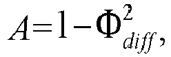


 Pdiff is the diffuse sound power,E{ } is an expectation value,
 N1 is diffuse sound in a first channel, andN2 is diffuse sound in a second channel.
 - The audio encoding device (3) according to claim 10,
wherein the de-correlation filter bank (32) is configured to perform the de-correlation of the diffuse sound power by generating three orthogonal diffuse sound components from the diffuse sound estimate power




 wherein D̃W [k,i] is a first channel diffuse sound component,wherein D̃X [k,i] is second channel diffuse sound component,wherein D̃Y [k,i] is third channel diffuse sound component,DFRW is a diffuse-field response of the first channel,DFRX is a diffuse-field response of the second channel,DFRY is a diffuse-field response of the third channel,wu is an exponential window,RT 60 is a reverberation time,U 1,U 2,U 3 is the de-correlation filter bank (32),u is Gaussian noise sequence,lu is a given length of the Gaussian noise sequence, andP 2D-diff is the diffuse noise power.
 - The audio encoding device (3) according to claims 1 and 6, or 1 and 8, or 1 and 6 and 8,
comprising an adder (41), configured to add channel-wise, the first-order ambisonic B-format direct sound signals and- the higher order ambisonic B-format direct sound signals, and/or- the diffuse sound signals, resulting in complete ambisonic B-format signals. - An audio recording device (1) comprising N microphones (2, 2a, 2b, 2c) configured to record the N audio signals, and an audio encoding device (3) according to any of the preceding claims.
- A method for encoding N audio signals, from N microphones (2, 2a, 2b, 2c) where N ≥ 3, the method comprising:- estimating (101) angles of incidence of direct sound by estimating for each pair of the N audio signals an angle of incidence of direct sound,- deriving (102) A-format direct sound signals from the estimated angles of incidence by deriving from each estimated angle of incidence an A-format direct sound signal, each A-format direct sound signal being a first-order virtual microphone signal, and- encoding the A-format direct sound signals in first-order ambisonic B-format direct sound signals by applying a transformation matrix to the A-format direct sound signals.
- A computer program with a program code for performing the method according to claim 14 when the computer program runs on a computer.
Applications Claiming Priority (1)
| Application Number | Priority Date | Filing Date | Title |
|---|---|---|---|
| PCT/EP2018/056411 WO2019174725A1 (en) | 2018-03-14 | 2018-03-14 | Audio encoding device and method |
Publications (2)
| Publication Number | Publication Date |
|---|---|
| EP3753263A1 EP3753263A1 (en) | 2020-12-23 |
| EP3753263B1 true EP3753263B1 (en) | 2022-08-24 |
Family
ID=61683788
Family Applications (1)
| Application Number | Title | Priority Date | Filing Date |
|---|---|---|---|
| EP18711541.5A Active EP3753263B1 (en) | 2018-03-14 | 2018-03-14 | Audio encoding device and method |
Country Status (4)
| Country | Link |
|---|---|
| US (1) | US11632626B2 (en) |
| EP (1) | EP3753263B1 (en) |
| CN (1) | CN111819862B (en) |
| WO (1) | WO2019174725A1 (en) |
Families Citing this family (6)
| Publication number | Priority date | Publication date | Assignee | Title |
|---|---|---|---|---|
| US10878536B1 (en) | 2017-12-29 | 2020-12-29 | Gopro, Inc. | Apparatus and methods for non-uniform downsampling of captured panoramic images |
| CN113661538B (en) * | 2019-04-12 | 2024-11-15 | 华为技术有限公司 | Device and method for obtaining a first-order ambisonic reverberation signal |
| US11546691B2 (en) | 2020-06-04 | 2023-01-03 | Northwestern Polytechnical University | Binaural beamforming microphone array |
| CN112259110B (en) * | 2020-11-17 | 2022-07-01 | 北京声智科技有限公司 | Audio encoding method and device and audio decoding method and device |
| JP2023131911A (en) * | 2022-03-10 | 2023-09-22 | 株式会社ズーム | Software and microphone devices |
| CN119603622A (en) * | 2025-02-10 | 2025-03-11 | 深圳市沃莱特电子有限公司 | Microphone welding direction detection method, device, computer equipment and medium |
Family Cites Families (7)
| Publication number | Priority date | Publication date | Assignee | Title |
|---|---|---|---|---|
| EP1737271A1 (en) * | 2005-06-23 | 2006-12-27 | AKG Acoustics GmbH | Array microphone |
| WO2014034555A1 (en) * | 2012-08-29 | 2014-03-06 | シャープ株式会社 | Audio signal playback device, method, program, and recording medium |
| EP2733965A1 (en) * | 2012-11-15 | 2014-05-21 | Fraunhofer-Gesellschaft zur Förderung der angewandten Forschung e.V. | Apparatus and method for generating a plurality of parametric audio streams and apparatus and method for generating a plurality of loudspeaker signals |
| EP2738762A1 (en) * | 2012-11-30 | 2014-06-04 | Aalto-Korkeakoulusäätiö | Method for spatial filtering of at least one first sound signal, computer readable storage medium and spatial filtering system based on cross-pattern coherence |
| EP3005344A4 (en) * | 2013-05-31 | 2017-02-22 | Nokia Technologies OY | An audio scene apparatus |
| CN205249484U (en) * | 2015-12-30 | 2016-05-18 | 临境声学科技江苏有限公司 | Microphone linear array reinforcing directive property adapter |
| US10595146B2 (en) * | 2017-12-21 | 2020-03-17 | Verizon Patent And Licensing Inc. | Methods and systems for extracting location-diffused ambient sound from a real-world scene |
-
2018
- 2018-03-14 EP EP18711541.5A patent/EP3753263B1/en active Active
- 2018-03-14 WO PCT/EP2018/056411 patent/WO2019174725A1/en not_active Ceased
- 2018-03-14 CN CN201880090899.7A patent/CN111819862B/en active Active
-
2020
- 2020-09-14 US US17/019,757 patent/US11632626B2/en active Active
Also Published As
| Publication number | Publication date |
|---|---|
| EP3753263A1 (en) | 2020-12-23 |
| CN111819862B (en) | 2021-10-22 |
| US11632626B2 (en) | 2023-04-18 |
| CN111819862A (en) | 2020-10-23 |
| WO2019174725A1 (en) | 2019-09-19 |
| US20210067868A1 (en) | 2021-03-04 |
Similar Documents
| Publication | Publication Date | Title |
|---|---|---|
| US12283279B2 (en) | Method and device for decoding an audio soundfield representation | |
| US11368790B2 (en) | Apparatus, method and computer program for encoding, decoding, scene processing and other procedures related to DirAC based spatial audio coding | |
| US11632626B2 (en) | Audio encoding device and method | |
| EP3777235B9 (en) | Spatial audio capture | |
| JP2015502716A (en) | Microphone positioning apparatus and method based on spatial power density | |
| KR20130127987A (en) | Apparatus and method for deriving a directional information and computer program product | |
| Olgun et al. | Sound field interpolation via sparse plane wave decomposition for 6DoF immersive audio | |
| AU2021282442B2 (en) | Method and device for decoding an audio soundfield representation | |
| WO2020221431A1 (en) | Device and method for rendering a binaural audio signal | |
| AU2020201419B2 (en) | Method and device for decoding an audio soundfield representation |
Legal Events
| Date | Code | Title | Description |
|---|---|---|---|
| STAA | Information on the status of an ep patent application or granted ep patent |
Free format text: STATUS: UNKNOWN |
|
| STAA | Information on the status of an ep patent application or granted ep patent |
Free format text: STATUS: THE INTERNATIONAL PUBLICATION HAS BEEN MADE |
|
| PUAI | Public reference made under article 153(3) epc to a published international application that has entered the european phase |
Free format text: ORIGINAL CODE: 0009012 |
|
| STAA | Information on the status of an ep patent application or granted ep patent |
Free format text: STATUS: REQUEST FOR EXAMINATION WAS MADE |
|
| 17P | Request for examination filed |
Effective date: 20200916 |
|
| AK | Designated contracting states |
Kind code of ref document: A1 Designated state(s): AL AT BE BG CH CY CZ DE DK EE ES FI FR GB GR HR HU IE IS IT LI LT LU LV MC MK MT NL NO PL PT RO RS SE SI SK SM TR |
|
| AX | Request for extension of the european patent |
Extension state: BA ME |
|
| DAV | Request for validation of the european patent (deleted) | ||
| DAX | Request for extension of the european patent (deleted) | ||
| GRAP | Despatch of communication of intention to grant a patent |
Free format text: ORIGINAL CODE: EPIDOSNIGR1 |
|
| STAA | Information on the status of an ep patent application or granted ep patent |
Free format text: STATUS: GRANT OF PATENT IS INTENDED |
|
| INTG | Intention to grant announced |
Effective date: 20220407 |
|
| GRAS | Grant fee paid |
Free format text: ORIGINAL CODE: EPIDOSNIGR3 |
|
| GRAA | (expected) grant |
Free format text: ORIGINAL CODE: 0009210 |
|
| STAA | Information on the status of an ep patent application or granted ep patent |
Free format text: STATUS: THE PATENT HAS BEEN GRANTED |
|
| AK | Designated contracting states |
Kind code of ref document: B1 Designated state(s): AL AT BE BG CH CY CZ DE DK EE ES FI FR GB GR HR HU IE IS IT LI LT LU LV MC MK MT NL NO PL PT RO RS SE SI SK SM TR |
|
| REG | Reference to a national code |
Ref country code: CH Ref legal event code: EP |
|
| REG | Reference to a national code |
Ref country code: DE Ref legal event code: R096 Ref document number: 602018039672 Country of ref document: DE |
|
| REG | Reference to a national code |
Ref country code: IE Ref legal event code: FG4D |
|
| REG | Reference to a national code |
Ref country code: AT Ref legal event code: REF Ref document number: 1514514 Country of ref document: AT Kind code of ref document: T Effective date: 20220915 |
|
| REG | Reference to a national code |
Ref country code: LT Ref legal event code: MG9D |
|
| REG | Reference to a national code |
Ref country code: NL Ref legal event code: MP Effective date: 20220824 |
|
| PG25 | Lapsed in a contracting state [announced via postgrant information from national office to epo] |
Ref country code: SE Free format text: LAPSE BECAUSE OF FAILURE TO SUBMIT A TRANSLATION OF THE DESCRIPTION OR TO PAY THE FEE WITHIN THE PRESCRIBED TIME-LIMIT Effective date: 20220824 Ref country code: RS Free format text: LAPSE BECAUSE OF FAILURE TO SUBMIT A TRANSLATION OF THE DESCRIPTION OR TO PAY THE FEE WITHIN THE PRESCRIBED TIME-LIMIT Effective date: 20220824 Ref country code: PT Free format text: LAPSE BECAUSE OF FAILURE TO SUBMIT A TRANSLATION OF THE DESCRIPTION OR TO PAY THE FEE WITHIN THE PRESCRIBED TIME-LIMIT Effective date: 20221226 Ref country code: NO Free format text: LAPSE BECAUSE OF FAILURE TO SUBMIT A TRANSLATION OF THE DESCRIPTION OR TO PAY THE FEE WITHIN THE PRESCRIBED TIME-LIMIT Effective date: 20221124 Ref country code: NL Free format text: LAPSE BECAUSE OF FAILURE TO SUBMIT A TRANSLATION OF THE DESCRIPTION OR TO PAY THE FEE WITHIN THE PRESCRIBED TIME-LIMIT Effective date: 20220824 Ref country code: LV Free format text: LAPSE BECAUSE OF FAILURE TO SUBMIT A TRANSLATION OF THE DESCRIPTION OR TO PAY THE FEE WITHIN THE PRESCRIBED TIME-LIMIT Effective date: 20220824 Ref country code: LT Free format text: LAPSE BECAUSE OF FAILURE TO SUBMIT A TRANSLATION OF THE DESCRIPTION OR TO PAY THE FEE WITHIN THE PRESCRIBED TIME-LIMIT Effective date: 20220824 Ref country code: FI Free format text: LAPSE BECAUSE OF FAILURE TO SUBMIT A TRANSLATION OF THE DESCRIPTION OR TO PAY THE FEE WITHIN THE PRESCRIBED TIME-LIMIT Effective date: 20220824 |
|
| REG | Reference to a national code |
Ref country code: AT Ref legal event code: MK05 Ref document number: 1514514 Country of ref document: AT Kind code of ref document: T Effective date: 20220824 |
|
| PG25 | Lapsed in a contracting state [announced via postgrant information from national office to epo] |
Ref country code: PL Free format text: LAPSE BECAUSE OF FAILURE TO SUBMIT A TRANSLATION OF THE DESCRIPTION OR TO PAY THE FEE WITHIN THE PRESCRIBED TIME-LIMIT Effective date: 20220824 Ref country code: IS Free format text: LAPSE BECAUSE OF FAILURE TO SUBMIT A TRANSLATION OF THE DESCRIPTION OR TO PAY THE FEE WITHIN THE PRESCRIBED TIME-LIMIT Effective date: 20221224 Ref country code: HR Free format text: LAPSE BECAUSE OF FAILURE TO SUBMIT A TRANSLATION OF THE DESCRIPTION OR TO PAY THE FEE WITHIN THE PRESCRIBED TIME-LIMIT Effective date: 20220824 Ref country code: GR Free format text: LAPSE BECAUSE OF FAILURE TO SUBMIT A TRANSLATION OF THE DESCRIPTION OR TO PAY THE FEE WITHIN THE PRESCRIBED TIME-LIMIT Effective date: 20221125 |
|
| PG25 | Lapsed in a contracting state [announced via postgrant information from national office to epo] |
Ref country code: SM Free format text: LAPSE BECAUSE OF FAILURE TO SUBMIT A TRANSLATION OF THE DESCRIPTION OR TO PAY THE FEE WITHIN THE PRESCRIBED TIME-LIMIT Effective date: 20220824 Ref country code: RO Free format text: LAPSE BECAUSE OF FAILURE TO SUBMIT A TRANSLATION OF THE DESCRIPTION OR TO PAY THE FEE WITHIN THE PRESCRIBED TIME-LIMIT Effective date: 20220824 Ref country code: ES Free format text: LAPSE BECAUSE OF FAILURE TO SUBMIT A TRANSLATION OF THE DESCRIPTION OR TO PAY THE FEE WITHIN THE PRESCRIBED TIME-LIMIT Effective date: 20220824 Ref country code: DK Free format text: LAPSE BECAUSE OF FAILURE TO SUBMIT A TRANSLATION OF THE DESCRIPTION OR TO PAY THE FEE WITHIN THE PRESCRIBED TIME-LIMIT Effective date: 20220824 Ref country code: CZ Free format text: LAPSE BECAUSE OF FAILURE TO SUBMIT A TRANSLATION OF THE DESCRIPTION OR TO PAY THE FEE WITHIN THE PRESCRIBED TIME-LIMIT Effective date: 20220824 Ref country code: AT Free format text: LAPSE BECAUSE OF FAILURE TO SUBMIT A TRANSLATION OF THE DESCRIPTION OR TO PAY THE FEE WITHIN THE PRESCRIBED TIME-LIMIT Effective date: 20220824 |
|
| REG | Reference to a national code |
Ref country code: DE Ref legal event code: R097 Ref document number: 602018039672 Country of ref document: DE |
|
| PG25 | Lapsed in a contracting state [announced via postgrant information from national office to epo] |
Ref country code: SK Free format text: LAPSE BECAUSE OF FAILURE TO SUBMIT A TRANSLATION OF THE DESCRIPTION OR TO PAY THE FEE WITHIN THE PRESCRIBED TIME-LIMIT Effective date: 20220824 Ref country code: EE Free format text: LAPSE BECAUSE OF FAILURE TO SUBMIT A TRANSLATION OF THE DESCRIPTION OR TO PAY THE FEE WITHIN THE PRESCRIBED TIME-LIMIT Effective date: 20220824 |
|
| P01 | Opt-out of the competence of the unified patent court (upc) registered |
Effective date: 20230524 |
|
| PG25 | Lapsed in a contracting state [announced via postgrant information from national office to epo] |
Ref country code: AL Free format text: LAPSE BECAUSE OF FAILURE TO SUBMIT A TRANSLATION OF THE DESCRIPTION OR TO PAY THE FEE WITHIN THE PRESCRIBED TIME-LIMIT Effective date: 20220824 |
|
| PLBE | No opposition filed within time limit |
Free format text: ORIGINAL CODE: 0009261 |
|
| STAA | Information on the status of an ep patent application or granted ep patent |
Free format text: STATUS: NO OPPOSITION FILED WITHIN TIME LIMIT |
|
| 26N | No opposition filed |
Effective date: 20230525 |
|
| PG25 | Lapsed in a contracting state [announced via postgrant information from national office to epo] |
Ref country code: SI Free format text: LAPSE BECAUSE OF FAILURE TO SUBMIT A TRANSLATION OF THE DESCRIPTION OR TO PAY THE FEE WITHIN THE PRESCRIBED TIME-LIMIT Effective date: 20220824 |
|
| PG25 | Lapsed in a contracting state [announced via postgrant information from national office to epo] |
Ref country code: MC Free format text: LAPSE BECAUSE OF FAILURE TO SUBMIT A TRANSLATION OF THE DESCRIPTION OR TO PAY THE FEE WITHIN THE PRESCRIBED TIME-LIMIT Effective date: 20220824 |
|
| REG | Reference to a national code |
Ref country code: CH Ref legal event code: PL |
|
| REG | Reference to a national code |
Ref country code: BE Ref legal event code: MM Effective date: 20230331 |
|
| PG25 | Lapsed in a contracting state [announced via postgrant information from national office to epo] |
Ref country code: LU Free format text: LAPSE BECAUSE OF NON-PAYMENT OF DUE FEES Effective date: 20230314 |
|
| REG | Reference to a national code |
Ref country code: IE Ref legal event code: MM4A |
|
| PG25 | Lapsed in a contracting state [announced via postgrant information from national office to epo] |
Ref country code: LI Free format text: LAPSE BECAUSE OF NON-PAYMENT OF DUE FEES Effective date: 20230331 Ref country code: IE Free format text: LAPSE BECAUSE OF NON-PAYMENT OF DUE FEES Effective date: 20230314 Ref country code: FR Free format text: LAPSE BECAUSE OF NON-PAYMENT OF DUE FEES Effective date: 20230331 Ref country code: CH Free format text: LAPSE BECAUSE OF NON-PAYMENT OF DUE FEES Effective date: 20230331 |
|
| PG25 | Lapsed in a contracting state [announced via postgrant information from national office to epo] |
Ref country code: BE Free format text: LAPSE BECAUSE OF NON-PAYMENT OF DUE FEES Effective date: 20230331 |
|
| PG25 | Lapsed in a contracting state [announced via postgrant information from national office to epo] |
Ref country code: IT Free format text: LAPSE BECAUSE OF FAILURE TO SUBMIT A TRANSLATION OF THE DESCRIPTION OR TO PAY THE FEE WITHIN THE PRESCRIBED TIME-LIMIT Effective date: 20220824 |
|
| PG25 | Lapsed in a contracting state [announced via postgrant information from national office to epo] |
Ref country code: BG Free format text: LAPSE BECAUSE OF FAILURE TO SUBMIT A TRANSLATION OF THE DESCRIPTION OR TO PAY THE FEE WITHIN THE PRESCRIBED TIME-LIMIT Effective date: 20220824 |
|
| PG25 | Lapsed in a contracting state [announced via postgrant information from national office to epo] |
Ref country code: BG Free format text: LAPSE BECAUSE OF FAILURE TO SUBMIT A TRANSLATION OF THE DESCRIPTION OR TO PAY THE FEE WITHIN THE PRESCRIBED TIME-LIMIT Effective date: 20220824 |
|
| PG25 | Lapsed in a contracting state [announced via postgrant information from national office to epo] |
Ref country code: CY Free format text: LAPSE BECAUSE OF FAILURE TO SUBMIT A TRANSLATION OF THE DESCRIPTION OR TO PAY THE FEE WITHIN THE PRESCRIBED TIME-LIMIT; INVALID AB INITIO Effective date: 20180314 |
|
| PG25 | Lapsed in a contracting state [announced via postgrant information from national office to epo] |
Ref country code: HU Free format text: LAPSE BECAUSE OF FAILURE TO SUBMIT A TRANSLATION OF THE DESCRIPTION OR TO PAY THE FEE WITHIN THE PRESCRIBED TIME-LIMIT; INVALID AB INITIO Effective date: 20180314 |
|
| PG25 | Lapsed in a contracting state [announced via postgrant information from national office to epo] |
Ref country code: TR Free format text: LAPSE BECAUSE OF FAILURE TO SUBMIT A TRANSLATION OF THE DESCRIPTION OR TO PAY THE FEE WITHIN THE PRESCRIBED TIME-LIMIT Effective date: 20220824 |
|
| PGFP | Annual fee paid to national office [announced via postgrant information from national office to epo] |
Ref country code: GB Payment date: 20260202 Year of fee payment: 9 |
|
| PGFP | Annual fee paid to national office [announced via postgrant information from national office to epo] |
Ref country code: DE Payment date: 20260204 Year of fee payment: 9 |