EP1737271A1 - Array microphone - Google Patents

Array microphone Download PDF

Info

Publication number
EP1737271A1
EP1737271A1 EP05450112A EP05450112A EP1737271A1 EP 1737271 A1 EP1737271 A1 EP 1737271A1 EP 05450112 A EP05450112 A EP 05450112A EP 05450112 A EP05450112 A EP 05450112A EP 1737271 A1 EP1737271 A1 EP 1737271A1
Authority
EP
European Patent Office
Prior art keywords
microphone
microphones
signals
basic
sound field
Prior art date
Legal status (The legal status is an assumption and is not a legal conclusion. Google has not performed a legal analysis and makes no representation as to the accuracy of the status listed.)
Withdrawn
Application number
EP05450112A
Other languages
German (de)
French (fr)
Inventor
Friedrich Reining
Current Assignee (The listed assignees may be inaccurate. Google has not performed a legal analysis and makes no representation or warranty as to the accuracy of the list.)
AKG Acoustics GmbH
Original Assignee
AKG Acoustics GmbH
Priority date (The priority date is an assumption and is not a legal conclusion. Google has not performed a legal analysis and makes no representation as to the accuracy of the date listed.)
Filing date
Publication date
Application filed by AKG Acoustics GmbH filed Critical AKG Acoustics GmbH
Priority to EP05450112A priority Critical patent/EP1737271A1/en
Publication of EP1737271A1 publication Critical patent/EP1737271A1/en
Withdrawn legal-status Critical Current

Links

Images

Classifications

    • H—ELECTRICITY
    • H04—ELECTRIC COMMUNICATION TECHNIQUE
    • H04R—LOUDSPEAKERS, MICROPHONES, GRAMOPHONE PICK-UPS OR LIKE ACOUSTIC ELECTROMECHANICAL TRANSDUCERS; ELECTRIC HEARING AIDS; PUBLIC ADDRESS SYSTEMS
    • H04R5/00—Stereophonic arrangements
    • H04R5/027—Spatial or constructional arrangements of microphones, e.g. in dummy heads
    • H—ELECTRICITY
    • H04—ELECTRIC COMMUNICATION TECHNIQUE
    • H04S—STEREOPHONIC SYSTEMS 
    • H04S3/00—Systems employing more than two channels, e.g. quadraphonic
    • H—ELECTRICITY
    • H04—ELECTRIC COMMUNICATION TECHNIQUE
    • H04R—LOUDSPEAKERS, MICROPHONES, GRAMOPHONE PICK-UPS OR LIKE ACOUSTIC ELECTROMECHANICAL TRANSDUCERS; ELECTRIC HEARING AIDS; PUBLIC ADDRESS SYSTEMS
    • H04R2201/00—Details of transducers, loudspeakers or microphones covered by H04R1/00 but not provided for in any of its subgroups
    • H04R2201/40—Details of arrangements for obtaining desired directional characteristic by combining a number of identical transducers covered by H04R1/40 but not provided for in any of its subgroups
    • H04R2201/401—2D or 3D arrays of transducers
    • H—ELECTRICITY
    • H04—ELECTRIC COMMUNICATION TECHNIQUE
    • H04S—STEREOPHONIC SYSTEMS 
    • H04S2400/00—Details of stereophonic systems covered by H04S but not provided for in its groups
    • H04S2400/15—Aspects of sound capture and related signal processing for recording or reproduction
    • H—ELECTRICITY
    • H04—ELECTRIC COMMUNICATION TECHNIQUE
    • H04S—STEREOPHONIC SYSTEMS 
    • H04S2420/00—Techniques used stereophonic systems covered by H04S but not provided for in its groups
    • H04S2420/11—Application of ambisonics in stereophonic audio systems

Definitions

  • the invention relates to an array microphone, which is formed from at least two basic microphones connected with a signal processor, which make use of an algorithm for processing the signals of the basic microphone.
  • the invention relates to a method for modeling an array microphone made from basic microphones, where the signals of the basic microphones are processed using a filter algorithm.
  • array microphones are used, on the one hand, as natural speech microphones in telephone conversations, for example, in private cars, and, on the other hand, in systems such as navigation systems operated by voice recognition.
  • Adaptive beam formers can, in the process, adapt to movable sources of interference that change over time, for example, during the start phase, the flight phase, and the landing phase of an airplane.
  • An input requirement for the functioning of a beam former is that it must be provided the directions from which useful or interfering sound can be expected. This information, however, can also change over time, or it can be calculated by an additional algorithm with the aid of the microphone signals, for example, if there are several pilots in a cockpit, whose movements are to be tracked.
  • Array microphones essentially consist of an arrangement of individual microphones, which are interconnected by signal technology. In the arrangement of the microphones, a distinction can in principle be made between array microphones in a one-, two- and three-dimensional arrangement. In the case of the one-dimensional arrangement, the microphones are arranged along a line. If microphones that have a spherical directivity pattern (so called omnidirectional microphones) are used, the orientation of the individual microphones is not essential, because they only function as pressure receivers and therefore have an undirected effect in space.
  • the overall directivity pattern, and thus the overall directionality of the array microphone, are the result of a combination of the directivity patterns of the individual microphones with respect to each other, with the use of an algorithm by means of which the microphone signals are processed jointly.
  • the signal-technology connection of the individual microphones can be carried out in the analog or the digital domain.
  • the individual signals of the basic microphones are digitized by means of A/D converters (analog-digital converters) and applied to a signal processing unit.
  • A/D converters analog-digital converters
  • an appropriate algorithm key word "beam forming"
  • the degree of directionality of array microphones can be increased, and interfering sound sources that act from certain directions can be suppressed.
  • a good review of array microphones can be found, for example, in M. Brandstein and D. Wards (Editors), Microphone Arrays, Springer Verlag, 2001 and in the literature cited therein.
  • One component of the algorithm consists of filter coefficient sets, which are characteristic for the arrangement, type, sensitivity, and characteristic of the microphones used, the acoustic environment, and the location of the sound sources.
  • filter coefficient sets it is also possible to take into account different properties of the individual microphones, such as those caused by scattering due to the method of manufacture, aging effects, etc.
  • a filter structure that is frequently used in the literature is known as a "filter and sum beam former" (see, for example, M. Brandstein and D. Wards (Editors), Microphone Arrays, Springer Verlag, 2001, page 159).
  • the individual microphone signals are filtered after the analog-digital conversion using appropriate FIR filters (finite impulse response filters), then added.
  • FIR filters finite impulse response filters
  • the above-mentioned filter coefficient sets are calculated in many applications for a fixed predetermined standard situation and are used as constant parameters in the operation of the array microphone.
  • the individual microphones which comprise the array microphone, are known to specialists under the term "basic microphones", an expression that will also be used in the following description.
  • array microphones function on the principle of constructive or destructive superposition of signals.
  • pressure microphone omnidirectional microphone capsules
  • other pressure gradient microphones microphone capsules whose directivity pattern differs from the omnidirectional characteristic, such as the cardioid pattern
  • the pre-established boundary conditions such as the main direction (this is the direction of maximum sensitivity for the microphone) and/or the direction of rejection (this is the direction of lowest sensitivity of the microphone, where it exhibits the greatest sound suppression)
  • the filter coefficients using optimization algorithms. If the microphone signals are filtered using these filter coefficients, then the given boundary conditions for the entire microphone can be satisfied, more or less.
  • the pressure gradient microphone as basic microphones of the microphone array can bring about a partial improvement during the suppression of interfering sound of the overall microphone.
  • one uses varyingly complex adaptive systems which use the time dimension in addition to the 3 spatial dimensions.
  • the spectral properties of the useful sound or of the interfering sound can only be addressed unsatisfactorily.
  • the measures taken to change or adapt the desired overall microphone properties to fit the given requirements, or to movable sources of useful and/or interfering sound concentrate exclusively on the algorithms in the filter systems.
  • the resulting drawbacks are obvious: insufficient suppression of interfering sound, at times an unacceptable S/N ratio, and a limited degree of directionality (for the selective acquisition of the useful signal), as well as the absence of more efficient measures that would allow one to take into account the frequency dependence of the individual directivity patterns.
  • the objects of the invention are to solve this problem and to provide a method by means of which the signal/noise ratio is clearly improved, reaching a high degree of directionality, which allows flexible control of the microphone properties such as the directivity pattern, with the frequency dependence of the basic microphones being taken into account.
  • the method according to the invention for modeling an array microphone formed from basic microphones, with which the signals of the basic microphones are processed with a filter algorithm is characterized in that the basic microphones are sound field microphones and in that, from the B format signals of an individual sound field microphone, at least one signal is generated, whose directivity pattern is adjusted as a function of the position and type of one or more sound sources to be received, and optionally of sources of interfering sound, and in that the signals of the individual sound field microphones are processed, with the filter algorithm, into a microphone signal.
  • Sound field microphones (sometimes also referred to as B format microphones) consist of several pressure-gradient capsules, arranged on an imaginary spherical surface, which are simply called “capsules” below, in as symmetric as possible an arrangement.
  • B format microphones Sound field microphones
  • the great advantage of sound field microphones is that it is possible to change the directivity pattern of the overall microphone by an appropriate conversion by calculation of the individual signals.
  • B format signals it is possible, using different combinations of the so-called B format signals, to simultaneously generate several different signals.
  • a signal can be directed toward a speaking person, while another signal is directed toward a source of interfering sound.
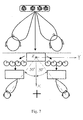
  • Figure 5 is an outline of the method for the determination of the filter coefficients for a filter algorithm of an array microphone according to the state of the art.
  • the directivity pattern of the individual basic microphones 1, 2, 3, and 4 is unchangeable, with each basic microphone generating only a single signal.
  • the beam forming, which is based on the signals of the basic microphones, is carried out in the subsequent filter 17, which generates the output signal 18 (overall microphone signal).
  • the expected overall characteristic of the array microphone is calculated (step 20).
  • the necessary filter coefficients are then calculated (step 21). This can also occur, for example, in an adaptive process involving several iterative steps, which can optimize the overall properties of the array microphone.
  • the present invention expands the state of the art by an additional dimension.
  • This dimension (in addition to the dimensions of space and time), describes the dynamic changeability of the direction effect of each individual basic microphone, for example, starting from a spherical directivity pattern and ranging to cardioid or a figure-eight directivity pattern.
  • Sound field microphones consist of pressure-gradient capsules, which are arranged as symmetrically as possible in the space formed by the surface of an imaginary sphere, and, in the case of four capsules, on the surface of a virtual tetrahedron.
  • the sound microphone 5 consists ⁇ as shown in Figure 2 ⁇ of four pressure-gradient capsules 10, 11, 12, and 13, where the individual capsules are in a tetrahedral arrangement so that the membranes of the individual capsules are essentially parallel to the tetrahedral surfaces.
  • the individual capsules are thus spherical or arranged around a sphere.
  • Each one of these individual capsules delivers its own signal A, B, C, or D.
  • the symmetrical axis of the directivity pattern of each individual microphone is perpendicular to the membrane or to the corresponding surface of the tetrahedron. Thus, the individual microphones present maxima of their directivity patterns in different directions.
  • the great advantage of the sound field microphones is that, after the storage in memory of the sound events received by the individual capsules, the directivity pattern of the overall microphone can be changed by an appropriate calculation of the individual signals, so it can be changed during the sound reproduction or the subsequent preparation of a sound carrier medium in the desired manner.
  • the sound field can be described using a sound field microphone in a point in space by the spherical harmonics of 0th, 1st, 2nd, ... etc., order, depending on the number and the arrangement of the capsules.
  • the four signals of the individual capsules (the so-called A format) are converted to the so-called B format (W, X, Y, Z), which is conventional in the state of the art.
  • the resulting signals consist of a sphere (W) and three figure-eights (X, Y, Z), which are orthogonal to each other and extend along the three spatial directions.
  • Figure 8 shows the directivity patterns of the separate individual capsule signals.
  • the main directions of the figures-eights are normal with respect to the faces of a cube that circumscribes the tetrahedron ( Figure 9).
  • the sound field recorded at the location of the microphone is split by means of such a microphone and by the associated calculation instruction into the spherical harmonics of 0th and first order.
  • W is a spherical harmonic function of 0th order
  • X, Y, and Z are spherical harmonic functions of 1 st order.
  • Figure 3 shows a block diagram, which schematically illustrates how the signals A, B, C, and D of capsules 10, 11, 12, and 13 of a sound field microphone 5 are converted by a matrix 6 according to the above indicated calculation instruction, into the B format (W, X, Y, and Z). Appropriate amplifiers are switched between the capsules and the matrix. Filters 14, 15, 16, and 17 ensure the equalization of the B format signals.
  • the equalized signals are denoted as W', X', Y', and Z'.
  • any desired directivity pattern with the desired preferential direction for the generated overall signal can be obtained.
  • Such a combination of the individual signals via the B format is also called “synthesizing” or “modeling” a microphone. The weighting can be carried out separately for each signal, which also allows the synthesis of frequency-dependent directivity patterns.
  • a great advantage of such microphones is that the desired directivity patterns can also be adjusted even after the sound event has taken place by an appropriate mixing of the individual B format signals.
  • An additional important advantage of sound field microphones is that, in contrast to pressure-gradient capsules, several signals can be generated simultaneously. These signals, which originate from a single sound-field microphone, can naturally be different, and are produced by different combinations of B format signals. Consequently, it is possible to use a single sound-field microphone to simultaneously acquire sound sources that are arranged in different positions. For example, the directivity pattern of a signal can be directed toward the driver of a private car, while the directivity pattern of another signal is directed toward the front seat passenger.
  • the invention is naturally not limited to sound field microphones of first order.
  • the sound field can also be represented by spherical harmonics of the second order or higher.
  • the sensing of a sound field by a capsule group with overlapping directivity patterns offers a "mathematically clean" possibility to receive and reproduce a spatial sound field (periphony, ambisonics, orthophony).
  • a spatial sound field periphony, ambisonics, orthophony.
  • All the B format signals are orthogonal to each other.
  • the sound field is thus split, by sound field microphones, into mutually orthogonal components.
  • This orthogonality allows a differentiated representation of a sound field, which allows the combination of two or more, optionally weighted, B format signals in a controlled manner to generate a microphone signal having the desired directivity pattern.
  • Separation of the sound field into B format signals, which additionally also contain spherical harmonics of the second order, allows an even more differentiated representation of the sound field and an even higher spatial resolution.
  • a sound field microphone 5' which represents the spherical harmonics up to the second order, requires twelve individual gradient microphone capsules that ⁇ as shown in Figure 4 ⁇ are arranged in the form of a dodecahedron, where each front face carries a capsule. The designation of the capsule starts on the front face with "a” and it ends on the right with "1".
  • a Cartesian coordinate system is assumed, in which the normal vectors of the individual capsules are defined as follows.
  • the B format with the known signals of the 0th order and 1st order W, X, Y, Z must now be enlarged with additional signals corresponding to the spherical signal components of second order. These 5 signals are denoted with the letters R, S, T, U, and V.
  • R, S, T, U, and V the connections between the capsule signals s1, s1 Vietnameses12 and the associated B format signals W, X, Y, Z, R, S, T, U, and V are represented.
  • the array microphone 30 is formed from basic microphones, which here are sound field microphones 5a, 5b, 5c, 5d and thus have several capsules arranged around the imaginary spherical surface.
  • the sound field microphones are essentially coincident microphones, because they are all in an interconnected arrangement. Deviations from these coincident conditions occur only if the capsules cannot be arranged at a certain point because of the space they take up. Nevertheless, the assumption that a microphone is coincident is valid up to a certain frequency.
  • independent filters 22c, 22b, 2c, 22d also called basic microphone filters
  • one or more signals is (are) synthesized first for each sound field microphone on its B format signals.
  • the directivity pattern of each individual signal is adjusted as a function of the given requirements 25, such as the main sound direction(s), direction of the interfering sound, and degree of directionality, frequency response, etc. (step 26).
  • This parameterization is carried out separately for each one of the individual basic microphones and separately for the individual resulting signals as a function of the position and type of the sound sources to be received, and optionally as a function of the interfering sound sources.
  • the array microphone according to the invention has the capacity of splitting up complex requirements ⁇ such as several useful sound directions or interfering sound directions ⁇ into simple partial requirements. These partial requirements are satisfied by several signals, which differ from each other and which are generated in each case by the appropriate combination of B format signals. For each individual partial requirement, an optimal basic microphone filter must accordingly be calculated (on this topic, see the embodiment example below). The result of this procedure produces several signals, all directed toward different sound sources.
  • the synthesis of signals is thus achieved by the linear combination of B format signals.
  • the requirements for how these B format signals should be combined can differ for different frequencies or frequency ranges, on the one hand, to take into account the frequency-dependent directivity patterns of the individual capsules and, on the other hand, to be able to optimally adapt to the frequency characteristic of useful and interfering sound sources.
  • These input requirements (as shown in the embodiment example below, they involve the use of weighting factors, angle and direction data, etc.) correspond to filter coefficients, which are calculated in step 27, by means of which the signals of the basic microphones are synthesized in the basic microphone filters 22a-22d.
  • each basic microphone signal can provide algorithms (one for each basic microphone signal) that optimize the directivity pattern and its frequency variation in accordance with the input requirements.
  • each one of these algorithms in no way takes account of the respective other basic microphones.
  • the signals generated by the basic microphone filter reach the array filter 23, which, taking into account the same input requirements and optionally additional parameters, for example, frequency spectrum of the useful and interfering sound, movable or changing sound sources, spatial expansion of a sound source, etc., generates the starting signal 24 of the array microphone according to the invention.
  • the array filter is essentially a signal processor, which applies a filter algorithm to the individual signals algorithm and generates an output signal from them.
  • an optimization of its filter coefficients can be carried out in accordance with the given input requirements. Via back coupling and iteration, the optimization process can simultaneously optimize the parameters of the individual basic microphone filters.
  • Figure 6 shows the course of the optimization of an array microphone 30 according to the invention.
  • the main direction and the optimal direction effect are set, for example, hypo cardioid, cardioid, hypercardioid, etc., for the individual signals of the basic microphones (step 26).
  • the number of signals generated from the B format of a single basic microphone preferably corresponds to the number of sound sources to be received, including the interfering sound sources to be taken into account. In the case of a single sound source, there may be only one signal for each sound field microphone.
  • any number of signals can be used, depending on the required number.
  • all this involves signal-technology processing by an appropriate number, weighting, and combination of individual B format signals of a basic microphone.
  • the position and type of interfering sound sources constitute an important criterion in this adjustment.
  • the goal is to achieve as good as possible a suppression of interfering sound. This procedure is preferably carried out for all frequencies or several frequency ranges.
  • the information concerning main directions and the direction effect of the individual signal is stored in the form of filter coefficients (which are calculated in step 27) and in the form of an appropriate algorithm in the basic microphone filters 22a-22b.
  • the characteristic of the entire array microphone is calculated (step 28).
  • interfering secondary lobes are determined and compared with the input requirements.
  • modified basic microphone parameters can now be calculated (step 29).
  • the basic microphone parameters are used again as input for the calculation of the overall characteristic, until it satisfies the input requirements or approximates such.
  • modified filter coefficients can be calculated for the array filter 23, in a calculation that is performed while taking into consideration the basic microphone parameters (step 32 in Figure 6).
  • An array microphone is considered, which is formed from four sound field microphones.
  • the input requirement one uses a known direction from which the useful sound is expected. Interfering sound from all other directions should be suppressed to the extent possible. However, the type and manner of the interfering sound varies.
  • All the sound field microphones are adjusted to hypercardioid, to achieve a maximum degree of directionality, and are directed with their main direction in each case being toward the useful sound source.
  • one synthesizes--for example, for one of the sound field microphones--one additional basic microphone signal which, however, presents a temporally varying directivity pattern, that is, one that , for example, rotates in space with an angular speed to allow the dynamic acquisition of interfering sound sources from all directions (scanning).
  • each basic microphone signal can be optimized in order to suppress the interfering sound source to the extent possible (for example, by rotating the basic microphone main direction, or changing the directivity pattern). This optimization can be carried out for different frequencies or frequency ranges, for example, to eliminate an interfering sound source that presents only high frequencies. The interfering sound source is thus optimally eliminated for each individual basic microphone.
  • the filter algorithm of the filter 23 can also take into account this information in the calculation of its filter parameters and thus optimize the output signal 24.
  • the filter algorithm can be a least mean square (LMS) algorithm that, with the help of Lagrange multipliers, also takes into account that information via the basic microphone signals in the form of secondary conditions.
  • LMS least mean square
  • an appropriate measuring means an additional algorithm, which, for example, can make distinctions based on the spectral distribution between useful and interfering sound
  • the entire process can be run several times using an iteration procedure.
  • Figure 7 shows an embodiment of the invention.
  • the starting point is the acquisition of two persons (driver and front seat passenger in a private car) by four basic microphones and a filter algorithm or a so-called beam former algorithm.
  • Conventional procedures calculate, via a filter algorithm, a double lobe, as shown in the top part of Figure 7.
  • omnidirectional capsules are used as basic microphones, the useful signal or interfering signal directions are not adjusted better, however, the suppression of the interfering sound is subject only to the filter algorithm or the beam former algorithm.
  • pressure gradient capsules they can optimally be directed only toward one useful sound source (or suboptimally to both). The suppression of interfering sound can now also occur at the base capsules, but only for a fixed or predetermined position of the useful sound sources.
  • a set of basic microphone signals is first synthesized, where the signals are oriented in the direction toward the driver; an additional set of basic microphone signals is provided, which are all rotated in the direction of the front seat passenger.
  • the interfering sound signals are already largely eliminated by the optimal orientation of the basic microphones 5a-5b or the basic microphone signals for each useful sound direction.
  • a one-dimensional array with 4 sound field microphones arranged equidistantly is intended to be directed toward the driver and the front seat passenger in a private car in an optimal manner and to optimally dampen the noise from the air cooler of the dashboard (in the middle close to the stick shift).
  • a FIR filter--in filter 23 an LMS (least mean squares algorithm)--is to be used.
  • the directions of the useful sound (driver, front seat passenger) as well as of the interfering sound (ventilator, not shown) are assumed to be constant.
  • the middle of the array (between the two lower sound-field microphones) is taken as the origin of the underlying overall coordinate system.
  • the XZ plane is defined as the plane between the driver and the front seat passenger.
  • the array thus extends one dimensionally along the Y axis.
  • the driver and front seat passenger forms, with the X axis, an angle of ⁇ 30° and is located in the XY plane; the ventilator (not shown) is in the direction of the negative Z axis below the array.
  • the individual B format signals are generated with the application of the above-mentioned transformation formulas.
  • All four sound field microphones are oriented in space in such a manner that the figure-eight signals of the B format assumes a position, with respect to the middle of each sound field microphone, along the X direction (X' is used to denote the figure-eight lobe of the first sound field microphone, which is parallel to the X axis of the overall coordinate system), the Y direction, and the Z direction.
  • the figure-eight lobes of the 3 additional sound field microphones are denoted X", Y", Z", X"', etc.
  • hypercardioid patterns are generated from the B format signals. This occurs with the application of corresponding weighting factors between the omnidirectional signal and figure-eight signals.
  • the weighting factor for the omnidirectional signal W is 0.25 and for the figure-eight signal X, Y, or Z or linear combinations thereof, it is 0.75.
  • Basic microphone signal directed to the driver 0.25 ⁇ W + 0.75 ⁇ X ⁇ cos 30 ⁇ Y ⁇ sin 30
  • Basic microphone signal directed to the front seat passenger 0.25 ⁇ W + 0.75 ⁇ X ⁇ cos 30 + Y ⁇ sin 30
  • Basic microphone signal directed to the ventilator 0.25 ⁇ W ⁇ 0.75 ⁇ Z .
  • all 4 sound field microphones are parameterized to the same angle of 30°, although the value of the angle deviates slightly from 30° for each microphone.
  • weighting factors (0.25 or 0.75) for the B format signals and angle indications (30°) for directions from which sound is expected, the individual sound sources are selectively acquired even before the processing of the individual basic microphone signals in the filter 23.
  • the beam forming algorithm which is here considered as an embodiment example, works on the principle of energy minimization.
  • the sound source for example, human mouth
  • the sound source sends out a wave front, which is to be received by the spatial arrangement of of each microphone at a different time.
  • the calculation is carried out in a small band, so the result can be interpreted as a vector of complex frequency points. If one runs the calculation in a loop, with the frequency as the loop parameter, one obtains a complex frequency response from which, as realization, a FIR filter can be determined.
  • the goal of the following representation is to force a minimization of the energy in the output signal, with the exception of the desired main direction, for which the energy should be 1.
  • w n is the complex weight, the nth entry in the optimized vector, whose magnitude and phase have an effect on the microphone signal;
  • H n ( ⁇ i , ⁇ ) is the complex directivity pattern for the individual frequency ⁇ i .
  • the superscript H in formula A5 indicates that the vector w is a Hermitian vector w, which is characterized in that w* (that is, the conjugate complex vector of w) is equal to the vector w.
  • ⁇ 0 is the instantaneously desired main acoustic incidence direction.
  • w ⁇ ⁇ A ⁇ 1 ⁇ m ⁇ 0
  • the matrix A represents the cross correlation between the individual microphone signals.
  • the autocorrelation functions of the individual microcapsules are on the main diagonals.
  • the so-called filter and sum beam former can be considered a special case of a beam forming algorithm calculated by the above method, when the filters are exclusively of the all-pass type (in the literature, also called delay and sum beam former). This type can be easily calculated using the above calculation procedure by omitting all the components of the matrix A, which cannot be found in the main diagonal.
  • the calculated complex weights w in the above-mentioned loop, yield a complex frequency response, which can be transformed into the time domain by inverse Fourier transformation (IFT), yielding the coefficients of a FIR (finite impulse response) filter.
  • IFT inverse Fourier transformation
  • Each basic microphone signal which is directed to the same sound source, is filtered using the specifically calculated FIR filter, then added.
  • This procedure is also called beam forming.
  • the input requirement (3 sound sources) was shaped into 3 beams, so 3 beam-forming algorithms are calculated in parallel and are available at the end.
  • the two useful signals produced in this manner are added to form a single useful signal, the interfering signal of the ventilator can now, after appropriate damping, also be subtracted from the useful signal, which can result in an additional improvement of the S/N ratio.
  • the array microphone consists of sound field microphones in an arrangement that is not equidistant. Because the principle of the beam former results from the superposition of waves having different phases, one can easily see that for wavelengths in the range of the capsule separation, constructive or destructive interference is very pronounced. Then, to cover as broad a frequency range as possible with the beam former algorithm, the capsule separations are chosen to be as different as possible.
  • the invention is not limited to the represented embodiment example; rather, it can be modified in different manners.
  • four basic microphones is not compulsory.
  • the arrangement of the basic microphones can also be in two or three dimensions. Sound field microphones of the 3rd or higher order would also be conceivable. It is also possible to combine sound field microphones with different capsule numbers and arrangements together in one array.
  • the noncoincident arrangement (array) of coincident (or at least approximately coincident) microphones, which are interconnected by signal technology, is important.
  • the different steps do not necessarily have to be in the described form, the essential factor being that one or more signals is/are first synthesized from the B format signals of each individual sound field microphone, which in part already satisfy the input requirements or partial input requirements, with these signals then being processed with a signal processor using a filter algorithm to form the overall microphone signal.

Landscapes

  • Physics & Mathematics (AREA)
  • Engineering & Computer Science (AREA)
  • Acoustics & Sound (AREA)
  • Signal Processing (AREA)
  • Circuit For Audible Band Transducer (AREA)
  • Obtaining Desirable Characteristics In Audible-Bandwidth Transducers (AREA)

Abstract

The invention relates to an array microphone (30), which is formed from at least two basic microphones connected with a signal processor, which makes use of an algorithm for the processing of the signals of the basic microphones.
The array microphone is characterized in that the basic microphones are sound field microphones (5, 5').

Description

  • The invention relates to an array microphone, which is formed from at least two basic microphones connected with a signal processor, which make use of an algorithm for processing the signals of the basic microphone.
  • The invention relates to a method for modeling an array microphone made from basic microphones, where the signals of the basic microphones are processed using a filter algorithm.
  • Language is becoming increasingly important as a means of communication between humans and machines. Because, in most applications, it is necessary to use natural speech, the microphone that receives the speech signal is not in close proximity to the mouth of the speaker; instead, it is at a certain distance from the person, which continuously changes in many applications. Thus, array microphones are used, on the one hand, as natural speech microphones in telephone conversations, for example, in private cars, and, on the other hand, in systems such as navigation systems operated by voice recognition.
  • However, a limiting factor of voice recognition is caused by the fact that the voice level, and thus the signal/noise ratio, decreases with increasing distance between the sound source and the microphone. In environments with many undesired sources of interference, such as in cockpits in airplanes, motor vehicles, conference rooms, lecture halls, and surgery rooms, measures must therefore be taken to suppress the interference. Naturally, the same applies, although at a more sensitive scale, to concert halls in which people rustle, clear their throats, and talk.
  • Efficient solutions for this set of problems are offered by so-called beam forming methods. Here, several microphones that are arranged to form an array, so-called array microphones, are used to receive the desired audio signal. As a result of the spatial arrangement of the individual microphones, with respect to one or more sound sources, as well as the filtering and the combination of the individual microphone signals, a spatial direction effect is generated. Signals that reach the array microphone from the useful signal direction are transmitted essentially without distortion, while signals from other directions can be suppressed considerably. Adaptive beam formers can, in the process, adapt to movable sources of interference that change over time, for example, during the start phase, the flight phase, and the landing phase of an airplane. An input requirement for the functioning of a beam former is that it must be provided the directions from which useful or interfering sound can be expected. This information, however, can also change over time, or it can be calculated by an additional algorithm with the aid of the microphone signals, for example, if there are several pilots in a cockpit, whose movements are to be tracked.
  • Array microphones essentially consist of an arrangement of individual microphones, which are interconnected by signal technology. In the arrangement of the microphones, a distinction can in principle be made between array microphones in a one-, two- and three-dimensional arrangement. In the case of the one-dimensional arrangement, the microphones are arranged along a line. If microphones that have a spherical directivity pattern (so called omnidirectional microphones) are used, the orientation of the individual microphones is not essential, because they only function as pressure receivers and therefore have an undirected effect in space. If pressure gradient microphones are used, the orientation of the individual microphones is essential: The overall directivity pattern, and thus the overall directionality of the array microphone, are the result of a combination of the directivity patterns of the individual microphones with respect to each other, with the use of an algorithm by means of which the microphone signals are processed jointly.
  • The signal-technology connection of the individual microphones can be carried out in the analog or the digital domain. Below, the digital implementation will be discussed. The individual signals of the basic microphones are digitized by means of A/D converters (analog-digital converters) and applied to a signal processing unit. By means of the signal processing unit, an appropriate algorithm (key word "beam forming") is applied to the microphone signal. With the use of this algorithm, the degree of directionality of array microphones can be increased, and interfering sound sources that act from certain directions can be suppressed. A good review of array microphones can be found, for example, in M. Brandstein and D. Wards (Editors), Microphone Arrays, Springer Verlag, 2001 and in the literature cited therein.
  • One component of the algorithm consists of filter coefficient sets, which are characteristic for the arrangement, type, sensitivity, and characteristic of the microphones used, the acoustic environment, and the location of the sound sources. In these filter coefficient sets, it is also possible to take into account different properties of the individual microphones, such as those caused by scattering due to the method of manufacture, aging effects, etc. A filter structure that is frequently used in the literature is known as a "filter and sum beam former" (see, for example, M. Brandstein and D. Wards (Editors), Microphone Arrays, Springer Verlag, 2001, page 159). Here, the individual microphone signals are filtered after the analog-digital conversion using appropriate FIR filters (finite impulse response filters), then added. An embodiment example with 4 microphones is shown in Figure 1, which reflects the state of the art:
    • Figure 1 shows a simple linear array microphone with identical distances "d" between the individual microphones. The angle of incidence of the sound, θ, is expressed with respect to the longitudinal axis of a microphone array. The incident sound source reaches the individual microphones of the array after different travel times. The travel time differences correspond to the path differences d x cos(θ). The FIR filters FIR1 to FIR4 (reference numeral 8), shown in Figure 1, contain the filter coefficient sets, which correspond to frequency-dependent amplitude and phase differences. After the filtration, the signals are added (filter and sum beam former). As a result of the mentioned amplitude and phase differences, sound waves, which arrive with certain directions of incidence, are reinforced by constructive superposition, and sound waves that come from other directions of incidence of sound are weakened by destructive superposition. As the simplest special case, one can think of the FIR filters FIR1 to FIR4 (reference numeral 8) as so-called all-pass filters, which all present the same frequency-independent delay. In this case, the sound waves are reinforced if their angle of incidence θ is 90°, with sound waves having any other direction of incidence being weakened; in this case one speaks of a so-called broadside array.
  • The above-mentioned filter coefficient sets are calculated in many applications for a fixed predetermined standard situation and are used as constant parameters in the operation of the array microphone.
  • The individual microphones, which comprise the array microphone, are known to specialists under the term "basic microphones", an expression that will also be used in the following description.
  • Thus, array microphones function on the principle of constructive or destructive superposition of signals. As the bases of array microphones, pressure microphone (omnidirectional microphone capsules) and other pressure gradient microphones (microphone capsules whose directivity pattern differs from the omnidirectional characteristic, such as the cardioid pattern) are used. In case of very simple algorithms, one uses as the starting assumption--in the case where individual microphone signals are linked to form an overall microphone signal, which is usually carried out with the use of digital signal processing ― an idealized representation; namely, one assumes that the same acoustic pressure is applied to all the basic microphones, with, however, different phases.
  • As a result of the pre-established boundary conditions, such as the main direction (this is the direction of maximum sensitivity for the microphone) and/or the direction of rejection (this is the direction of lowest sensitivity of the microphone, where it exhibits the greatest sound suppression), it is possible to calculate filter coefficients using optimization algorithms. If the microphone signals are filtered using these filter coefficients, then the given boundary conditions for the entire microphone can be satisfied, more or less.
  • If the marginal conditions are constant over time, that is, for example, if the main direction remains unchanged, then the pressure gradient microphone as basic microphones of the microphone array can bring about a partial improvement during the suppression of interfering sound of the overall microphone. To make the suppression of interfering sound more effective, it is often advantageous to adapt the direction of extinction dynamically to the circumstances. For this purpose, one uses varyingly complex adaptive systems, which use the time dimension in addition to the 3 spatial dimensions. However, in spite of the complexity of the algorithms used, it remains difficult, or even impossible, to satisfy the marginal conditions for frequencies whose wavelengths are close to the separations between the basic microphones (aliasing). As a result, the spectral properties of the useful sound or of the interfering sound can only be addressed unsatisfactorily.
  • Because of the fact that the basic microphones have fixed predetermined properties and different separations and orientations with respect to each other, the measures taken to change or adapt the desired overall microphone properties to fit the given requirements, or to movable sources of useful and/or interfering sound, concentrate exclusively on the algorithms in the filter systems. Thus, there is a limited tolerance in synthesizing an overall microphone signal from the individual signals of the basic microphones. The resulting drawbacks are obvious: insufficient suppression of interfering sound, at times an unacceptable S/N ratio, and a limited degree of directionality (for the selective acquisition of the useful signal), as well as the absence of more efficient measures that would allow one to take into account the frequency dependence of the individual directivity patterns.
  • The objects of the invention are to solve this problem and to provide a method by means of which the signal/noise ratio is clearly improved, reaching a high degree of directionality, which allows flexible control of the microphone properties such as the directivity pattern, with the frequency dependence of the basic microphones being taken into account.
  • According to the invention, these objectives are achieved with an array microphone, mentioned in the introduction, due the fact that the basic microphones are sound field microphones.
  • The method according to the invention for modeling an array microphone formed from basic microphones, with which the signals of the basic microphones are processed with a filter algorithm, is characterized in that the basic microphones are sound field microphones and in that, from the B format signals of an individual sound field microphone, at least one signal is generated, whose directivity pattern is adjusted as a function of the position and type of one or more sound sources to be received, and optionally of sources of interfering sound, and in that the signals of the individual sound field microphones are processed, with the filter algorithm, into a microphone signal.
  • Sound field microphones (sometimes also referred to as B format microphones) consist of several pressure-gradient capsules, arranged on an imaginary spherical surface, which are simply called "capsules" below, in as symmetric as possible an arrangement. The great advantage of sound field microphones is that it is possible to change the directivity pattern of the overall microphone by an appropriate conversion by calculation of the individual signals. In addition, it is possible, using different combinations of the so-called B format signals, to simultaneously generate several different signals. Thus, for example, a signal can be directed toward a speaking person, while another signal is directed toward a source of interfering sound.
  • The invention is explained in greater detail below with reference to drawings. In the drawings:
    • Figure 1 shows the signal-technology combination of signals of the basic microphones in an array microphone according to the state of the art,
    • Figure 2 shows a sound field microphone with four capsules arranged in a tetrahedral pattern around an imaginary spherical surface,
    • Figure 3 is a block diagram representing the signal-technology connections in the calculation, with equalization and synthesis of the B format signals of a sound field microphone according to Figure 2,
    • Figure 4 shows a sound field microphone with twelve capsules arranged in a dodecahedral pattern around a spherical surface,
    • Figure 5 shows a schematic representation of the adaptation of an array microphone to fit the given requirements according to the state of the art,
    • Figure 6 shows an array microphone according to the invention, with a schematic representation of the adaptation to requirements according to the method of the invention,
    • Figure 7 shows a schematic representation of the mechanism of action of an array microphone according to the state of the art along with an array microphone according to the invention,
    • Figure 8 shows the directivity patterns of the individual capsules of a sound field microphone according to Figure 2, and
    • Figure 9 shows the lobes of the B format (first-order spherical harmonics).
  • Figure 5 is an outline of the method for the determination of the filter coefficients for a filter algorithm of an array microphone according to the state of the art. The directivity pattern of the individual basic microphones 1, 2, 3, and 4 is unchangeable, with each basic microphone generating only a single signal. The beam forming, which is based on the signals of the basic microphones, is carried out in the subsequent filter 17, which generates the output signal 18 (overall microphone signal). Starting from the input requirements 19, such as the main direction(s) and the direction(s) of the interfering sound and of the degree of directionality, the expected overall characteristic of the array microphone is calculated (step 20). Taking into account, and following the analysis of, additional directions of interfering sound (interfering secondary lobes) with reference to the input requirement, the necessary filter coefficients are then calculated (step 21). This can also occur, for example, in an adaptive process involving several iterative steps, which can optimize the overall properties of the array microphone.
  • The present invention expands the state of the art by an additional dimension. This dimension (in addition to the dimensions of space and time), describes the dynamic changeability of the direction effect of each individual basic microphone, for example, starting from a spherical directivity pattern and ranging to cardioid or a figure-eight directivity pattern. To improve the understanding of the statements made above, a discussion of the state of the art is presented below.
  • In DE 44 36 272 A1 , whose disclosure is included in its entirety in this description, the combination of two microphone signals having different directivity patterns is described. For example, the addition of a "sphere" and a "figure-eight" leads to the "cardioid" directivity pattern. The input requirement here is that the amplitude of the two signals is equal. By weighting the individual amplitudes, the directivity patterns can continuously be adjusted between a sphere and a figure-eight, for example: hypo cardioid, cardioid, supercardioid, and hypercardioid. As described in this patent, the frequency response of each individual signal can be changed as desired before the addition of signals. By influencing the frequency response of said individual signals, the frequency response and the directivity pattern of the signal that has been generated by addition of signals can thus be changed as desired.
  • US 4,042,779 A (as well as the corresponding DE 25 31 161 A1 ), whose disclosure is included by reference in this description in its entirety, discloses a so-called sound field microphone. Sound field microphones consist of pressure-gradient capsules, which are arranged as symmetrically as possible in the space formed by the surface of an imaginary sphere, and, in the case of four capsules, on the surface of a virtual tetrahedron.
  • In the concrete case of US 4,042,779 A , the sound microphone 5 consists ― as shown in Figure 2 ― of four pressure- gradient capsules 10, 11, 12, and 13, where the individual capsules are in a tetrahedral arrangement so that the membranes of the individual capsules are essentially parallel to the tetrahedral surfaces. The individual capsules are thus spherical or arranged around a sphere. Each one of these individual capsules delivers its own signal A, B, C, or D. Each one of these pressure receivers presents directivity patterns that deviate from a sphere, and can be approximately represented by the formula (1 - k) + k x cos(θ), where θ denotes the azimuth, at which point the capsule is exposed to the sound, with the ratio factor k indicating how strongly the signal differs from a omnidirectional signal (in the case of a sphere, k = 0, and in the case of a figure-eight, k = 1). The symmetrical axis of the directivity pattern of each individual microphone is perpendicular to the membrane or to the corresponding surface of the tetrahedron. Thus, the individual microphones present maxima of their directivity patterns in different directions.
  • The great advantage of the sound field microphones is that, after the storage in memory of the sound events received by the individual capsules, the directivity pattern of the overall microphone can be changed by an appropriate calculation of the individual signals, so it can be changed during the sound reproduction or the subsequent preparation of a sound carrier medium in the desired manner. Thus it is possible, for example, to emphasize a certain solo player in an ensemble, to eliminate unexpected and undesired sound events by influencing the directivity pattern, or to follow a moving sound source (for example, an actor on the stage), so that the reception quality is always maintained independently of the changing position of the sound source. The sound field can be described using a sound field microphone in a point in space by the spherical harmonics of 0th, 1st, 2nd, ... etc., order, depending on the number and the arrangement of the capsules.
  • According to the calculation equations, the four signals of the individual capsules (the so-called A format) are converted to the so-called B format (W, X, Y, Z), which is conventional in the state of the art. The calculation equations for this purpose are: W = 1 / 2 ⁢ A + B + C + D
    Figure imgb0001
    X = 1 / 2 ⁢ A + B − C − D
    Figure imgb0002
    Y = 1 / 2 ⁢ − A + B + C − D
    Figure imgb0003
    Z = 1 / 2 ⁢ − A + B − C + D
    Figure imgb0004
  • The resulting signals consist of a sphere (W) and three figure-eights (X, Y, Z), which are orthogonal to each other and extend along the three spatial directions.
  • Figure 8 shows the directivity patterns of the separate individual capsule signals. The main directions of the figures-eights are normal with respect to the faces of a cube that circumscribes the tetrahedron (Figure 9). By the linear combination of at least two of these B format signals, it is again possible to synthesize any desired microphone capsule (in terms of spatial direction and directivity pattern).
  • The sound field recorded at the location of the microphone is split by means of such a microphone and by the associated calculation instruction into the spherical harmonics of 0th and first order. Thus, W is a spherical harmonic function of 0th order and X, Y, and Z are spherical harmonic functions of 1 st order.
  • Figure 3 shows a block diagram, which schematically illustrates how the signals A, B, C, and D of capsules 10, 11, 12, and 13 of a sound field microphone 5 are converted by a matrix 6 according to the above indicated calculation instruction, into the B format (W, X, Y, and Z). Appropriate amplifiers are switched between the capsules and the matrix. Filters 14, 15, 16, and 17 ensure the equalization of the B format signals. The equalized signals are denoted as W', X', Y', and Z'.
  • Depending on the desired directivity pattern of the sound field microphone 5, it is now possible to combine all, or only a few, of these B format signals by the linear combination, 7, a process which is also called "synthesis". For example, by combining a signal that presents a spherical directivity pattern with a signal which presents a figure-eight directivity pattern, one obtains a cardioid directivity pattern. By weighting the individual signals, any desired directivity pattern with the desired preferential direction for the generated overall signal can be obtained. Such a combination of the individual signals via the B format is also called "synthesizing" or "modeling" a microphone. The weighting can be carried out separately for each signal, which also allows the synthesis of frequency-dependent directivity patterns.
  • A great advantage of such microphones is that the desired directivity patterns can also be adjusted even after the sound event has taken place by an appropriate mixing of the individual B format signals. An additional important advantage of sound field microphones is that, in contrast to pressure-gradient capsules, several signals can be generated simultaneously. These signals, which originate from a single sound-field microphone, can naturally be different, and are produced by different combinations of B format signals. Consequently, it is possible to use a single sound-field microphone to simultaneously acquire sound sources that are arranged in different positions. For example, the directivity pattern of a signal can be directed toward the driver of a private car, while the directivity pattern of another signal is directed toward the front seat passenger.
  • The invention is naturally not limited to sound field microphones of first order. By using an appropriate number and arrangement of capsules, the sound field can also be represented by spherical harmonics of the second order or higher. The sensing of a sound field by a capsule group with overlapping directivity patterns offers a "mathematically clean" possibility to receive and reproduce a spatial sound field (periphony, ambisonics, orthophony). To achieve a high spatial resolution, it is desirable here to use spherical harmonics of the second order.
  • All the B format signals are orthogonal to each other. The sound field is thus split, by sound field microphones, into mutually orthogonal components. This orthogonality allows a differentiated representation of a sound field, which allows the combination of two or more, optionally weighted, B format signals in a controlled manner to generate a microphone signal having the desired directivity pattern. Separation of the sound field into B format signals, which additionally also contain spherical harmonics of the second order, allows an even more differentiated representation of the sound field and an even higher spatial resolution.
  • Below, a sound field microphone of second order will be examined. Such a microphone, is described, for example, in the dissertation "On the Theory of the Second-Order Soundfield Microphone" by Philip S. Cotterell, BSc, MSc, AMIEE, Department of Cybernetics, February 2002.
  • A sound field microphone 5', which represents the spherical harmonics up to the second order, requires twelve individual gradient microphone capsules that ― as shown in Figure 4 ― are arranged in the form of a dodecahedron, where each front face carries a capsule. The designation of the capsule starts on the front face with "a" and it ends on the right with "1". For an understanding of the following formulas, a Cartesian coordinate system is assumed, in which the normal vectors of the individual capsules are defined as follows.
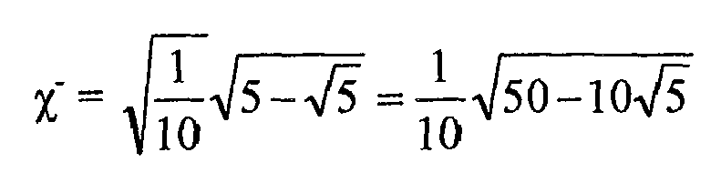
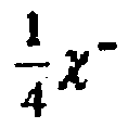
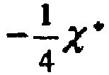
  • If two auxiliary quantities are introduced: χ + = 1 10 ⁢ 5 + 5 = 1 10 ⁢ 50 + 10 ⁢ 5
    Figure imgb0005
    χ − = 1 10 ⁢ 5 − 5 = 1 10 ⁢ 50 − 10 ⁢ 5
    Figure imgb0006

    these normal vectors û can be written simply: u ^ ‾ _ 1 = χ + 0 χ − T
    Figure imgb0007
    u ^ ‾ _ 2 = χ + 0 − χ − T
    Figure imgb0008
    u ^ ‾ _ 3 = − χ + 0 χ − T
    Figure imgb0009
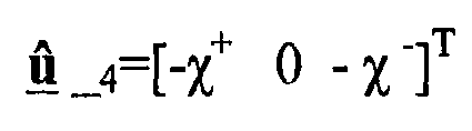
    u ^ ‾ _ 4 = − χ + 0 − χ − T
    Figure imgb0010
    u ^ ‾ _ 5 = χ − χ + 0 T
    Figure imgb0011
    u ^ ‾ _ 6 = − χ − χ + 0 T
    Figure imgb0012
    u ^ ‾ _ 7 = χ − − χ + 0 T
    Figure imgb0013
    u ^ ‾ _ 8 = − χ − − χ + 0 T
    Figure imgb0014
    u ^ ‾ _ 9 = 0 χ − χ + T
    Figure imgb0015
    u ^ ‾ _ 10 = 0 − χ − χ + T
    Figure imgb0016
    u ^ ‾ _ 11 = 0 χ − − χ + T
    Figure imgb0017
    u ^ ‾ _ 12 = 0 − χ − − χ + T
    Figure imgb0018
  • The B format with the known signals of the 0th order and 1st order W, X, Y, Z must now be enlarged with additional signals corresponding to the spherical signal components of second order. These 5 signals are denoted with the letters R, S, T, U, and V. In the following table, the connections between the capsule signals s1, s1.....s12 and the associated B format signals W, X, Y, Z, R, S, T, U, and V are represented. Table:
    W X Y Z R S T U V
    s1 1 12
    Figure imgb0019
    1 4 ⁢ χ +
    Figure imgb0020
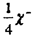
    0 1 4 ⁢ χ −
    Figure imgb0021
    5 48 ⁢ 5 − 3
    Figure imgb0022
    5 6
    Figure imgb0023
    5 24 ⁢ 1 + 5
    Figure imgb0024
    0
    s2 1 12
    Figure imgb0025
    1 4 ⁢ χ +
    Figure imgb0026
    0 − 1 4 ⁢ χ −
    Figure imgb0027
    5 48 ⁢ 5 − 3
    Figure imgb0028
    − 5 6
    Figure imgb0029
    0 5 24 ⁢ 1 + 5
    Figure imgb0030
    0
    s3 1 12
    Figure imgb0031
    − 1 4 ⁢ χ +
    Figure imgb0032
    0 1 4 ⁢ χ −
    Figure imgb0033
    5 48 ⁢ 5 − 3
    Figure imgb0034
    5 48 ⁢ 5 − 3
    Figure imgb0035
    − 5 6
    Figure imgb0036
    0 5 24 ⁢ 1 + 5
    Figure imgb0037
    0
    s4 1 12
    Figure imgb0038
    − 1 4 ⁢ χ +
    Figure imgb0039
    0 − 1 4 ⁢ χ −
    Figure imgb0040
    5 48 ⁢ 5 − 3
    Figure imgb0041
    5 6
    Figure imgb0042
    0 5 24 ⁢ 1 + 5
    Figure imgb0043
    0
    s5 1 12
    Figure imgb0044
    1 4 ⁢ χ −
    Figure imgb0045
    1 4 ⁢ χ −
    Figure imgb0046
    0 − 5 24
    Figure imgb0047
    0 0 − 5 12
    Figure imgb0048
    5 6
    Figure imgb0049
    s6 1 12
    Figure imgb0050
    − 1 4 ⁢ χ −
    Figure imgb0051
    1 4 ⁢ χ −
    Figure imgb0052
    0 − 5 24
    Figure imgb0053
    0 0 − 5 12
    Figure imgb0054
    − 5 6
    Figure imgb0055
    s7 1 12
    Figure imgb0056
    1 4 ⁢ χ −
    Figure imgb0057
    − 1 4 ⁢ χ −
    Figure imgb0058
    0 − 5 24
    Figure imgb0059
    0 0 − 5 12
    Figure imgb0060
    − 5 6
    Figure imgb0061
    s8 1 12
    Figure imgb0062
    − 1 4 ⁢ χ −
    Figure imgb0063
    − 1 4 ⁢ χ −
    Figure imgb0064
    0 − 5 24
    Figure imgb0065
    0 0 − 5 12
    Figure imgb0066
    5 6
    Figure imgb0067
    s9 1 12
    Figure imgb0068
    0 1 4 ⁢ χ −
    Figure imgb0069
    1 4 ⁢ χ +
    Figure imgb0070
    5 48 ⁢ 5 + 3
    Figure imgb0071
    0 5 6
    Figure imgb0072
    5 24 ⁢ 1 − 5
    Figure imgb0073
    0
    s10 1 12
    Figure imgb0074
    0 − 1 4 ⁢ χ −
    Figure imgb0075
    1 4 ⁢ χ +
    Figure imgb0076
    5 48 ⁢ 5 + 3
    Figure imgb0077
    0 − 5 6
    Figure imgb0078
    5 24 ⁢ 1 − 5
    Figure imgb0079
    0
    s11 1 12
    Figure imgb0080
    0 1 4 ⁢ χ −
    Figure imgb0081
    − 1 4 ⁢ χ +
    Figure imgb0082
    5 48 ⁢ 5 + 3
    Figure imgb0083
    0 − 5 6
    Figure imgb0084
    5 24 ⁢ 1 − 5
    Figure imgb0085
    0
    s12 1 12
    Figure imgb0086
    0 − 1 4 ⁢ χ −
    Figure imgb0087
    − 1 4 ⁢ χ +
    Figure imgb0088
    5 48 ⁢ 5 + 3
    Figure imgb0089
    0 5 6
    Figure imgb0090
    5 24 ⁢ 1 − 5
    Figure imgb0091
    0
  • One must again take into account the above introduced constant auxiliary values χ+ and χ-, which are helpful in making the formulas readable.
  • The advantages resulting from the use of sound field microphones are fully exploited in the context of the present invention. The invention will now be described in greater detail with reference to Figure 6.
  • The array microphone 30 according to the invention is formed from basic microphones, which here are sound field microphones 5a, 5b, 5c, 5d and thus have several capsules arranged around the imaginary spherical surface. The sound field microphones are essentially coincident microphones, because they are all in an interconnected arrangement. Deviations from these coincident conditions occur only if the capsules cannot be arranged at a certain point because of the space they take up. Nevertheless, the assumption that a microphone is coincident is valid up to a certain frequency.
  • By means of independent filters 22c, 22b, 2c, 22d (represented only schematically), also called basic microphone filters, one or more signals is (are) synthesized first for each sound field microphone on its B format signals. Here, the directivity pattern of each individual signal is adjusted as a function of the given requirements 25, such as the main sound direction(s), direction of the interfering sound, and degree of directionality, frequency response, etc. (step 26). This parameterization is carried out separately for each one of the individual basic microphones and separately for the individual resulting signals as a function of the position and type of the sound sources to be received, and optionally as a function of the interfering sound sources.
  • As mentioned before, it should be emphasized in particular that, in this context, the array microphone according to the invention has the capacity of splitting up complex requirements ― such as several useful sound directions or interfering sound directions ― into simple partial requirements. These partial requirements are satisfied by several signals, which differ from each other and which are generated in each case by the appropriate combination of B format signals. For each individual partial requirement, an optimal basic microphone filter must accordingly be calculated (on this topic, see the embodiment example below). The result of this procedure produces several signals, all directed toward different sound sources.
  • In the case of sound field microphones, the synthesis of signals is thus achieved by the linear combination of B format signals. The requirements for how these B format signals should be combined can differ for different frequencies or frequency ranges, on the one hand, to take into account the frequency-dependent directivity patterns of the individual capsules and, on the other hand, to be able to optimally adapt to the frequency characteristic of useful and interfering sound sources. These input requirements (as shown in the embodiment example below, they involve the use of weighting factors, angle and direction data, etc.) correspond to filter coefficients, which are calculated in step 27, by means of which the signals of the basic microphones are synthesized in the basic microphone filters 22a-22d.
  • Naturally, one can provide algorithms (one for each basic microphone signal) that optimize the directivity pattern and its frequency variation in accordance with the input requirements. However, each one of these algorithms in no way takes account of the respective other basic microphones. For example, as will be described later in an embodiment example, it is possible to use the dynamic signal evaluation of sound field microphones to determine, with greater precision, the position, type, and movement of a sound source. This information is then used for the optimization of the basic microphone filter.
  • As shown in Figure 6, the signals generated by the basic microphone filter reach the array filter 23, which, taking into account the same input requirements and optionally additional parameters, for example, frequency spectrum of the useful and interfering sound, movable or changing sound sources, spatial expansion of a sound source, etc., generates the starting signal 24 of the array microphone according to the invention. Thus, the array filter is essentially a signal processor, which applies a filter algorithm to the individual signals algorithm and generates an output signal from them.
  • Depending on the complexity of the filter algorithm, an optimization of its filter coefficients can be carried out in accordance with the given input requirements. Via back coupling and iteration, the optimization process can simultaneously optimize the parameters of the individual basic microphone filters.
  • Figure 6 shows the course of the optimization of an array microphone 30 according to the invention. First, the main direction and the optimal direction effect are set, for example, hypo cardioid, cardioid, hypercardioid, etc., for the individual signals of the basic microphones (step 26). In the process, it is also possible to generate several signals having a different directivity pattern for each basic microphone. The number of signals generated from the B format of a single basic microphone preferably corresponds to the number of sound sources to be received, including the interfering sound sources to be taken into account. In the case of a single sound source, there may be only one signal for each sound field microphone.
  • However, any number of signals can be used, depending on the required number. Naturally, all this involves signal-technology processing by an appropriate number, weighting, and combination of individual B format signals of a basic microphone. Besides the type, position, and spatial expansion of the sound source to be received, the position and type of interfering sound sources constitute an important criterion in this adjustment. The goal is to achieve as good as possible a suppression of interfering sound. This procedure is preferably carried out for all frequencies or several frequency ranges. The information concerning main directions and the direction effect of the individual signal is stored in the form of filter coefficients (which are calculated in step 27) and in the form of an appropriate algorithm in the basic microphone filters 22a-22b.
  • Then, starting from the signals of the basic microphones and using a filter algorithm that is stored in the filter 23, the characteristic of the entire array microphone is calculated (step 28). At the same time, interfering secondary lobes are determined and compared with the input requirements. On the basis of these differences between the output and input requirements, for the purpose of optimization, modified basic microphone parameters can now be calculated (step 29). In an iteration process (step 31), the basic microphone parameters are used again as input for the calculation of the overall characteristic, until it satisfies the input requirements or approximates such.
  • At the same time, modified filter coefficients can be calculated for the array filter 23, in a calculation that is performed while taking into consideration the basic microphone parameters (step 32 in Figure 6).
  • Below, the invention will be explained in greater detail with reference to an embodiment example: An array microphone is considered, which is formed from four sound field microphones. As the input requirement, one uses a known direction from which the useful sound is expected. Interfering sound from all other directions should be suppressed to the extent possible. However, the type and manner of the interfering sound varies.
  • 1. Initialization phase:
  • All the sound field microphones are adjusted to hypercardioid, to achieve a maximum degree of directionality, and are directed with their main direction in each case being toward the useful sound source. Independently of the synthesized basic microphone signal, one synthesizes--for example, for one of the sound field microphones--one additional basic microphone signal, which, however, presents a temporally varying directivity pattern, that is, one that , for example, rotates in space with an angular speed to allow the dynamic acquisition of interfering sound sources from all directions (scanning).
  • 2. Adaptation phase (Adaptation to changes in the interfering sound)
  • If an interfering sound source is located, then each basic microphone signal can be optimized in order to suppress the interfering sound source to the extent possible (for example, by rotating the basic microphone main direction, or changing the directivity pattern). This optimization can be carried out for different frequencies or frequency ranges, for example, to eliminate an interfering sound source that presents only high frequencies. The interfering sound source is thus optimally eliminated for each individual basic microphone.
  • The information on the new properties of the basic microphone signals, such as the main directions, and direction effect (which can also be frequency dependent), is now applied to the filter algorithm of the filter 23, which can also take into account this information in the calculation of its filter parameters and thus optimize the output signal 24. In concrete terms, the filter algorithm can be a least mean square (LMS) algorithm that, with the help of Lagrange multipliers, also takes into account that information via the basic microphone signals in the form of secondary conditions.
  • If an appropriate measuring means (an additional algorithm, which, for example, can make distinctions based on the spectral distribution between useful and interfering sound) is available for the objective measurement of an improvement of the S/N ratio, the entire process can be run several times using an iteration procedure.
  • As a result of the presented interplay of parameterizable basic microphone signals of an array microphone, that is, signals whose properties can be changed by appropriate signal processing independently of the other basic microphone signals, and by means of a multistep optimization algorithm, a number of advantages can be achieved:
    • The signal to noise ratio (hereafter called the S/N ratio) of the signals processed by the filter algorithm is already improved previously by targeted gradient formation in each individual basic microphone. Improvements compared to the state of the art--in which use is made of gradient microphones that are already permanently incorporated--are achieved both by the flexible control of the main direction (that is, the orientation of the basic microphones) and by the free choice of the basic microphone directivity pattern. It is important to have the possibility of generating more than one signal at once that differ from each other and are based on the B format signals of a single sound field microphone.
    • By the free choice of the basic microphone directivity pattern for each frequency, one can additionally adapt to the spectral properties of the useful sound or the interfering sound. Thus, if the spectrum of the useful signal or interfering signal is known, the frequency-dependent basic microphone directivity pattern can be adapted accordingly and optimized.
    • One-dimensional arrays (that is, for example, 4 microphones arranged along the Z axis of a Cartesian coordinate system), if omnidirectional capsules are used, allow only beams that are located in a toroid arrangement having rotational symmetry with respect to the Z axis (for example, in the X-Y plane). By using pressure gradient capsules, one can consider the result of the calculated beam to be a torus, which is weighted with the gradient capsule directivity pattern. According to the state of the art, if permanently incorporated pressure gradient capsules are used, one can thus direct their maximum sensitivity, for example, along the X axis of the given coordinate system, to generate only lobes in the XZ plane. If, instead of the pressure gradient capsules, one uses sound field microphones as basic microphones, it is possible to have an additional rotation of the lobe in the XY plane as well, and thus in all the spatial directions.
    • With the output signal of each basic microphone being dependent on only one signal-technology parameterization with subsequent filtering, it is also possible to calculate, for each basic microphone, several of these parameterizations and filtration operations simultaneously. In the calculation of a beam on two spatially separated useful sources (for example, the driver and front seat passenger), it is possible to calculate two individual beams with basic microphones that are optionally directed toward each useful sound source, and to add these two output signals. If, in contrast, one uses basic microphones according to the state of the art, then one can only use basic microphones with a spherical directivity pattern or gradient directivity pattern, which is directed between the two useful sources. The S/N ratio in both cases is worse than with basic microphones that are directed optimally toward each given speaker.
  • Using the procedure according to the invention, one can now generate microphone directivity patterns that would not be achievable by array microphones constructed from simple pressure gradient capsules. The reason is simply that an adaptation to the input requirements (for example, two or more main directions, etc.) is already carried out in part in the basic microphone.
  • Figure 7 shows an embodiment of the invention. The starting point is the acquisition of two persons (driver and front seat passenger in a private car) by four basic microphones and a filter algorithm or a so-called beam former algorithm. Conventional procedures calculate, via a filter algorithm, a double lobe, as shown in the top part of Figure 7. If omnidirectional capsules are used as basic microphones, the useful signal or interfering signal directions are not adjusted better, however, the suppression of the interfering sound is subject only to the filter algorithm or the beam former algorithm. If one uses pressure gradient capsules, they can optimally be directed only toward one useful sound source (or suboptimally to both). The suppression of interfering sound can now also occur at the base capsules, but only for a fixed or predetermined position of the useful sound sources.
  • In the invention (below the broken line), a set of basic microphone signals is first synthesized, where the signals are oriented in the direction toward the driver; an additional set of basic microphone signals is provided, which are all rotated in the direction of the front seat passenger. Before the calculation of the beam itself in the filter 23 is carried out, the interfering sound signals are already largely eliminated by the optimal orientation of the basic microphones 5a-5b or the basic microphone signals for each useful sound direction.
  • With reference to the embodiment example represented at the bottom of Figure 7, the possibility for optimizing a microphone signal will now be discussed, including the required calculation steps. The input requirements, which have already been mentioned above, will be formulated even more precisely in this example, and they will be expanded by one interfering sound source (not shown).
  • Application: A one-dimensional array with 4 sound field microphones arranged equidistantly is intended to be directed toward the driver and the front seat passenger in a private car in an optimal manner and to optimally dampen the noise from the air cooler of the dashboard (in the middle close to the stick shift). As the beam former algorithm, a FIR filter--in filter 23, an LMS (least mean squares algorithm)--is to be used.
  • The directions of the useful sound (driver, front seat passenger) as well as of the interfering sound (ventilator, not shown) are assumed to be constant. The middle of the array (between the two lower sound-field microphones) is taken as the origin of the underlying overall coordinate system. The XZ plane is defined as the plane between the driver and the front seat passenger. The array thus extends one dimensionally along the Y axis. The driver and front seat passenger forms, with the X axis, an angle of ±30° and is located in the XY plane; the ventilator (not shown) is in the direction of the negative Z axis below the array.
  • First, from the sound field microphones, the individual B format signals are generated with the application of the above-mentioned transformation formulas. All four sound field microphones are oriented in space in such a manner that the figure-eight signals of the B format assumes a position, with respect to the middle of each sound field microphone, along the X direction (X' is used to denote the figure-eight lobe of the first sound field microphone, which is parallel to the X axis of the overall coordinate system), the Y direction, and the Z direction. The figure-eight lobes of the 3 additional sound field microphones are denoted X", Y", Z", X"', etc. For clarification, see Figure 9.
  • For an optimal direction effect, hypercardioid patterns are generated from the B format signals. This occurs with the application of corresponding weighting factors between the omnidirectional signal and figure-eight signals. In the case of a hypercardioid, the weighting factor for the omnidirectional signal W is 0.25 and for the figure-eight signal X, Y, or Z or linear combinations thereof, it is 0.75. For each one of the individual partial input requirements, a separate signal is generated: Basic microphone signal   directed to the driver = 0.25 × W + 0.75 × X × cos 30 − Y × sin 30
    Figure imgb0092
    Basic microphone signal   directed to the front seat passenger = 0.25 × W + 0.75 × X × cos 30 + Y × sin 30
    Figure imgb0093
    Basic microphone signal   directed to the ventilator = 0.25 × W − 0.75 × Z .
    Figure imgb0094
  • For simplicity's sake, all 4 sound field microphones are parameterized to the same angle of 30°, although the value of the angle deviates slightly from 30° for each microphone. By using weighting factors (0.25 or 0.75) for the B format signals and angle indications (30°) for directions from which sound is expected, the individual sound sources are selectively acquired even before the processing of the individual basic microphone signals in the filter 23.
  • Overall, in this embodiment example, twelve basic microphone signals are thus generated, three from each sound field microphone. The signals of the basic microphones (basic microphone signal 1 (directed to the driver), basic microphone signal 2 (directed to the driver), basic microphone signal 3 (directed to the driver), basic microphone signal 4 (directed to the driver), basic microphone signal 1 (directed to the front seat passenger), ... etc.) are now applied to the beam former algorithm of filter 23, whose principle of operation will be examined more closely below.
  • For each useful sound source or interfering sound source, a specific beam forming algorithm is now used. The beam forming algorithm, which is here considered as an embodiment example, works on the principle of energy minimization.
  • Assuming that the sound field is planar, one finds that the output signal of the beam former R is dependent on the frequency ω and the angle θ (azimuth in the XY plane). R ω , θ = ∑ n = 0 N − 1 H n ω , θ ⁢ W n e j ⁢ ω ⁢ e j ⁢ ω ⁢ d λ ⁢ f s ⁢ cos θ
    Figure imgb0095
    • N     number of microphones
    • d     distance between the individual sound field microphones
    • fs     sampling frequency
    • λ     wavelength
    • Hn     microphone directivity pattern as a function of the angle of incidence of the sound and the frequency
    • Wn     the complex-valued weighting factors of the array algorithm, which are to be calculated.
  • The sound source (for example, human mouth) sends out a wave front, which is to be received by the spatial arrangement of of each microphone at a different time.
  • This fact is reflected in the expression of the time delay in the frequency domain: e j ⁢ ω ⁢ d λ ⁢ f s ⁢ cos θ
    Figure imgb0096

    which represents the sound field directivity pattern. The microphone properties, particularly the frequency response of the microphone and its directivity pattern, which changes with the frequency, is summarized in the function [summarized by the expression] Hn(ω,θ), and the vector Wn(ejω) can be written as a FIR filter structure. W n e j ⁢ ω = ∑ m = 0 M − 1 w m ⁢ n ⁢ e − j ⁢ m ⁢ ω ,   ω = 2 ⁢ π ⁢ f f s
    Figure imgb0097
  • The calculation is carried out in a small band, so the result can be interpreted as a vector of complex frequency points. If one runs the calculation in a loop, with the frequency as the loop parameter, one obtains a complex frequency response from which, as realization, a FIR filter can be determined. The goal of the following representation is to force a minimization of the energy in the output signal, with the exception of the desired main direction, for which the energy should be 1.
  • For the small band case, the formula is: R ω i , θ = ∑ n = 0 N − 1 H n ω i , θ ⁢ w n ⁢ e j ⁢ ω i ⁢ d λ ⁢ f s ⁢ cos θ
    Figure imgb0098
  • Herein, wn is the complex weight, the nth entry in the optimized vector, whose magnitude and phase have an effect on the microphone signal; Hn(ωi,θ) is the complex directivity pattern for the individual frequency ωi. For a simple mathematical description, one rewrites this in vector form:
  • With the representation of the sum as the product of the linear vector and the column vector, and with the combination of the delay component with the microphone properties (that is, the travel time due to the separation of the microphone from the origin of the overall coordinate system becomes part of the microphone directivity pattern of each individual basic microphone) to form an expression m(θ), the following applies: R θ = w H ⁢ m θ
    Figure imgb0099
  • The superscript H in formula A5 indicates that the vector w is a Hermitian vector w, which is characterized in that w* (that is, the conjugate complex vector of w) is equal to the vector w.
  • The representation of the received energy in an infinitesimal spatial range as the square of the value of the directivity patterns leads to the expression: min ∫ 0 2 ⁢ π ⁢ R ω i , θ 2 ⁢ sin θ ⁢ d ⁢ θ
    Figure imgb0100

    which, in a sufficient approximation, can be replaced by the sum min ∑ i ⁢ R θ i 2   0 ≤ θ i ≤ π
    Figure imgb0101

    Thus, written as vectors, one gets min ∑ i ⁢ w H ⁢ m θ ⁢ m H θ ⁢ w   with   A = ∑ i ⁢ m θ ⁢ m H θ
    Figure imgb0102

    which, using the minimization formulation, leads to min w ⁢ w H ⁢ A ⁢ w ,   w H ⁢ m θ 0 = 1
    Figure imgb0103

    which now needs to be evaluated. θ0 is the instantaneously desired main acoustic incidence direction. The secondary condition is reformulated in accordance with the optimization to: g w = w H ⁢ m θ − 1
    Figure imgb0104

    and the Lagrangian expression now yields a function that can be differentiated: L w , μ = w H ⁢ A ⁢ w + μ ⁢ w H ⁢ m θ 0 − 1
    Figure imgb0105
  • The differentiation is carried out for both variables w and µ, and it must disappear for extreme values; therefore: d ⁢ L d ⁢ w = A ⁢ w + μ ⁢ m θ 0 = 0
    Figure imgb0106
    d ⁢ L d ⁢ μ = w H ⁢ m θ 0 − 1 = 0
    Figure imgb0107
  • From the first equation, w can be expressed, however, as a function of the undetermined Lagrangian multiplier µ: w = μ ⁢ A − 1 ⁢ m θ 0
    Figure imgb0108
  • When substituting in the second differentiated equation: w H ⁢ m θ 0 = 1
    Figure imgb0109

    it becomes possible to calculate the still unknown µ. μ = − 1 m H θ 0 ⁢ A − 1 ⁢ m θ 0
    Figure imgb0110

    From which one finally gets, for the weight w: w = A − 1 ⁢ m θ m H θ 0 ⁢ A − 1 ⁢ m θ 0
    Figure imgb0111
  • In this connection, it should be noted that the matrix A represents the cross correlation between the individual microphone signals. The autocorrelation functions of the individual microcapsules are on the main diagonals. The so-called filter and sum beam former can be considered a special case of a beam forming algorithm calculated by the above method, when the filters are exclusively of the all-pass type (in the literature, also called delay and sum beam former). This type can be easily calculated using the above calculation procedure by omitting all the components of the matrix A, which cannot be found in the main diagonal.
  • The calculated complex weights w, in the above-mentioned loop, yield a complex frequency response, which can be transformed into the time domain by inverse Fourier transformation (IFT), yielding the coefficients of a FIR (finite impulse response) filter.
  • Each basic microphone signal, which is directed to the same sound source, is filtered using the specifically calculated FIR filter, then added. This procedure is also called beam forming. In the described embodiment example, the input requirement (3 sound sources) was shaped into 3 beams, so 3 beam-forming algorithms are calculated in parallel and are available at the end.
  • The two useful signals produced in this manner are added to form a single useful signal, the interfering signal of the ventilator can now, after appropriate damping, also be subtracted from the useful signal, which can result in an additional improvement of the S/N ratio.
  • In a preferred embodiment, the array microphone consists of sound field microphones in an arrangement that is not equidistant. Because the principle of the beam former results from the superposition of waves having different phases, one can easily see that for wavelengths in the range of the capsule separation, constructive or destructive interference is very pronounced. Then, to cover as broad a frequency range as possible with the beam former algorithm, the capsule separations are chosen to be as different as possible.
  • The invention is not limited to the represented embodiment example; rather, it can be modified in different manners. In particular, four basic microphones is not compulsory. One can of course use a larger or smaller number of sound field microphones in the array. Starting with at least two basic microphones, one already uses the term "array microphone". Naturally, the arrangement of the basic microphones can also be in two or three dimensions. Sound field microphones of the 3rd or higher order would also be conceivable. It is also possible to combine sound field microphones with different capsule numbers and arrangements together in one array. The noncoincident arrangement (array) of coincident (or at least approximately coincident) microphones, which are interconnected by signal technology, is important.
  • In the method according to the invention, the different steps do not necessarily have to be in the described form, the essential factor being that one or more signals is/are first synthesized from the B format signals of each individual sound field microphone, which in part already satisfy the input requirements or partial input requirements, with these signals then being processed with a signal processor using a filter algorithm to form the overall microphone signal.
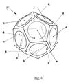
Claims (9)

  1. Array microphone (30) formed from at least two basic microphones connected with a signal processor, which makes use of an algorithm for processing the signals of the basic microphones, characterized in that the basic microphones are sound field microphones (5, 5').
  2. Array microphone according to Claim 1, characterized in that more than two sound field microphones (5, 5') are provided, with the corresponding separations between the sound field microphones (5, 5') being different.
  3. Array microphone according to Claim 1, characterized in that at least one sound field microphone (5, 5') is constructed from four tetrahedral individual capsules (10, 11, 12, 13), which are arranged around a spherical surface.
  4. Array microphone according to Claim 1, characterized in that at least one sound field microphone (5, 5') is constructed from twelve dodecahedral individual capsules (a, b, c, d, e, f, g, h, i, j, k,1), which are arranged around a spherical surface.
  5. Method for modeling an array microphone (30) made from basic microphones, where the signals of the basic microphones are processed by the use of a filter algorithm, characterized in that the basic microphones are sound field microphones (5, 5') and in that, by combining B format signals of each sound field microphone (5, 5'), at least one signal is generated, whose directivity pattern is adjusted as a function of the position and type of one or more sound sources to be received, and optionally of interfering sound sources, and characterized in that these signals of the individual sound field microphones (5, 5') are processed, using the filter algorithm, into a microphone signal (24).
  6. Method according to Claim 5, characterized in that the adjustment of the directivity pattern of the signals of the sound field microphone (5, 5') occurs as a function of the frequency.
  7. Method according to Claim 5, characterized in that at least one sound field microphone (5, 5') is used for the purpose of dynamically acquiring useful sound sources and/or interfering sound sources, and in that, as a result, the directivity patterns of the signal of the sound field microphone (5, 5') are modified accordingly.
  8. Method according to Claim 5, characterized in that the filter algorithm takes into account information on the directivity patterns of the individual signals of the sound field microphones (5, 5') for processing into one microphone signal (24).
  9. Method according to Claim 5, characterized in that, as a function of the overall characteristic of the array microphone (30), the directivity pattern of individual signals of the basic microphones (5, 5') is modified.
EP05450112A 2005-06-23 2005-06-23 Array microphone Withdrawn EP1737271A1 (en)

Priority Applications (1)

Application Number Priority Date Filing Date Title
EP05450112A EP1737271A1 (en) 2005-06-23 2005-06-23 Array microphone

Applications Claiming Priority (1)

Application Number Priority Date Filing Date Title
EP05450112A EP1737271A1 (en) 2005-06-23 2005-06-23 Array microphone

Publications (1)

Publication Number Publication Date
EP1737271A1 true EP1737271A1 (en) 2006-12-27

Family

ID=35266942

Family Applications (1)

Application Number Title Priority Date Filing Date
EP05450112A Withdrawn EP1737271A1 (en) 2005-06-23 2005-06-23 Array microphone

Country Status (1)

Country Link
EP (1) EP1737271A1 (en)

Cited By (16)

* Cited by examiner, † Cited by third party
Publication number Priority date Publication date Assignee Title
WO2009062211A1 (en) * 2007-11-13 2009-05-22 Akg Acoustics Gmbh Position determination of sound sources
WO2009062212A1 (en) * 2007-11-13 2009-05-22 Akg Acoustics Gmbh Microphone arrangement comprising three pressure gradient transducers
WO2009062213A1 (en) * 2007-11-13 2009-05-22 Akg Acoustics Gmbh Microphone arrangement, having two pressure gradient transducers
WO2009062210A1 (en) * 2007-11-13 2009-05-22 Akg Acoustics Gmbh Microphone arrangement
WO2009062214A1 (en) * 2007-11-13 2009-05-22 Akg Acoustics Gmbh Method for synthesizing a microphone signal
US8345898B2 (en) 2008-02-26 2013-01-01 Akg Acoustics Gmbh Transducer assembly
EP2592846A1 (en) * 2011-11-11 2013-05-15 Thomson Licensing Method and apparatus for processing signals of a spherical microphone array on a rigid sphere used for generating an Ambisonics representation of the sound field
KR20140091578A (en) * 2011-11-11 2014-07-21 톰슨 라이센싱 Method and apparatus for processing signals of a spherical microphone array on a rigid sphere used for generating an ambisonics representation of the sound field
US9173048B2 (en) 2011-08-23 2015-10-27 Dolby Laboratories Licensing Corporation Method and system for generating a matrix-encoded two-channel audio signal
US9407869B2 (en) 2012-10-18 2016-08-02 Dolby Laboratories Licensing Corporation Systems and methods for initiating conferences using external devices
WO2017152601A1 (en) * 2016-03-10 2017-09-14 中兴通讯股份有限公司 Microphone determination method and terminal
CN108632711A (en) * 2018-06-11 2018-10-09 广州大学 Sound reinforcement system gain-adaptive control method
WO2019174725A1 (en) * 2018-03-14 2019-09-19 Huawei Technologies Co., Ltd. Audio encoding device and method
US10477310B2 (en) 2017-08-24 2019-11-12 Qualcomm Incorporated Ambisonic signal generation for microphone arrays
CN110579275A (en) * 2019-10-21 2019-12-17 南京南大电子智慧型服务机器人研究院有限公司 Method for realizing sound field separation based on spherical vector microphone array
US12652488B2 (en) 2023-04-28 2026-06-09 Shure Acquisition Holdings, Inc. Ambisonic microphone

Citations (2)

* Cited by examiner, † Cited by third party
Publication number Priority date Publication date Assignee Title
DE2531161A1 (en) 1974-07-12 1976-01-22 Nat Research Dev Corp London MICROPHONE
DE4436272A1 (en) 1994-10-11 1996-04-18 Schalltechnik Dr Ing Schoeps G Influencing the directional characteristics of acousto-electrical receiver device with at least two microphones with different individual directional characteristics

Patent Citations (3)

* Cited by examiner, † Cited by third party
Publication number Priority date Publication date Assignee Title
DE2531161A1 (en) 1974-07-12 1976-01-22 Nat Research Dev Corp London MICROPHONE
US4042779A (en) 1974-07-12 1977-08-16 National Research Development Corporation Coincident microphone simulation covering three dimensional space and yielding various directional outputs
DE4436272A1 (en) 1994-10-11 1996-04-18 Schalltechnik Dr Ing Schoeps G Influencing the directional characteristics of acousto-electrical receiver device with at least two microphones with different individual directional characteristics

Non-Patent Citations (5)

* Cited by examiner, † Cited by third party
Title
"MICROPHONE ARRAYS", 2001, SPRINGER VERLAG
"MICROPHONE ARRAYS", 2001, SPRINGER VERLAG, pages: 159
DAVE MALHAM: "The role of the single point soundfield microphone in surround sound systems", 1998, pages 52 - 57, XP002354291, Retrieved from the Internet <URL:http://pddocserv/specdocs/data/handbooks/AES/UK-Cnf-Proc/1998LO03/1667.pdf> [retrieved on 20051116] *
MICHALE A. GERZON: "Microphone Techniques for 3-Channel Stereo", AUDIO ENGINEERING SOCIETY, October 1992 (1992-10-01), internet, XP002354290, Retrieved from the Internet <URL:http://pddocserv/specdocs/data/handbooks/AES/Conv-Preprints/1992/PP9210/3509.pdf> [retrieved on 20051116] *
PHILIP S. COTTERELL: "On the Theory of the Second-Order Soundfield Microphone", BSC, MSC, AMIEE, DEPARTMENT OF CYBER- NETICS, February 2002 (2002-02-01)

Cited By (29)

* Cited by examiner, † Cited by third party
Publication number Priority date Publication date Assignee Title
CN101911721B (en) * 2007-11-13 2014-04-23 Akg声学有限公司 Method for synthesizing a microphone signal
WO2009062212A1 (en) * 2007-11-13 2009-05-22 Akg Acoustics Gmbh Microphone arrangement comprising three pressure gradient transducers
WO2009062213A1 (en) * 2007-11-13 2009-05-22 Akg Acoustics Gmbh Microphone arrangement, having two pressure gradient transducers
WO2009062210A1 (en) * 2007-11-13 2009-05-22 Akg Acoustics Gmbh Microphone arrangement
WO2009062214A1 (en) * 2007-11-13 2009-05-22 Akg Acoustics Gmbh Method for synthesizing a microphone signal
CN101911721A (en) * 2007-11-13 2010-12-08 Akg声学有限公司 Methods of Synthesizing Microphone Signals
EP2262277A1 (en) * 2007-11-13 2010-12-15 AKG Acoustics GmbH Microphone arrangement
WO2009062211A1 (en) * 2007-11-13 2009-05-22 Akg Acoustics Gmbh Position determination of sound sources
US8472639B2 (en) 2007-11-13 2013-06-25 Akg Acoustics Gmbh Microphone arrangement having more than one pressure gradient transducer
US8345898B2 (en) 2008-02-26 2013-01-01 Akg Acoustics Gmbh Transducer assembly
US9173048B2 (en) 2011-08-23 2015-10-27 Dolby Laboratories Licensing Corporation Method and system for generating a matrix-encoded two-channel audio signal
CN104041074A (en) * 2011-11-11 2014-09-10 汤姆逊许可公司 Method and apparatus for processing signals of a spherical microphone array on a rigid sphere for producing an Ambisonics representation of a sound field
CN104041074B (en) * 2011-11-11 2017-04-12 杜比国际公司 Method and apparatus for processing signals of a spherical microphone array on a rigid sphere for producing an Ambisonics representation of a sound field
KR20140091578A (en) * 2011-11-11 2014-07-21 톰슨 라이센싱 Method and apparatus for processing signals of a spherical microphone array on a rigid sphere used for generating an ambisonics representation of the sound field
WO2013068284A1 (en) * 2011-11-11 2013-05-16 Thomson Licensing Method and apparatus for processing signals of a spherical microphone array on a rigid sphere used for generating an ambisonics representation of the sound field
EP2592846A1 (en) * 2011-11-11 2013-05-15 Thomson Licensing Method and apparatus for processing signals of a spherical microphone array on a rigid sphere used for generating an Ambisonics representation of the sound field
KR20140089601A (en) * 2011-11-11 2014-07-15 톰슨 라이센싱 Method and apparatus for processing signals of a spherical microphone array on a rigid sphere used for generating an ambisonics representation of the sound field
US9420372B2 (en) 2011-11-11 2016-08-16 Dolby Laboratories Licensing Corporation Method and apparatus for processing signals of a spherical microphone array on a rigid sphere used for generating an ambisonics representation of the sound field
US9407869B2 (en) 2012-10-18 2016-08-02 Dolby Laboratories Licensing Corporation Systems and methods for initiating conferences using external devices
WO2017152601A1 (en) * 2016-03-10 2017-09-14 中兴通讯股份有限公司 Microphone determination method and terminal
US10477310B2 (en) 2017-08-24 2019-11-12 Qualcomm Incorporated Ambisonic signal generation for microphone arrays
CN111819862A (en) * 2018-03-14 2020-10-23 华为技术有限公司 Audio encoding device and method
WO2019174725A1 (en) * 2018-03-14 2019-09-19 Huawei Technologies Co., Ltd. Audio encoding device and method
US11632626B2 (en) 2018-03-14 2023-04-18 Huawei Technologies Co., Ltd. Audio encoding device and method
CN111819862B (en) * 2018-03-14 2021-10-22 华为技术有限公司 Audio encoding device and method
CN108632711A (en) * 2018-06-11 2018-10-09 广州大学 Sound reinforcement system gain-adaptive control method
CN108632711B (en) * 2018-06-11 2020-09-04 广州大学 Gain Adaptive Control Method of Sound Reinforcement System
CN110579275A (en) * 2019-10-21 2019-12-17 南京南大电子智慧型服务机器人研究院有限公司 Method for realizing sound field separation based on spherical vector microphone array
US12652488B2 (en) 2023-04-28 2026-06-09 Shure Acquisition Holdings, Inc. Ambisonic microphone

Similar Documents

Publication Publication Date Title
JP4873913B2 (en) Sound source separation system, sound source separation method, and acoustic signal acquisition apparatus
US12262193B2 (en) Audio source spatialization relative to orientation sensor and output
JP4987358B2 (en) Microphone modeling
EP3320692B1 (en) Spatial audio processing apparatus
JP3521914B2 (en) Super directional microphone array
EP1466498B1 (en) Audio system based on at least second order eigenbeams
EP2777298B1 (en) Method and apparatus for processing signals of a spherical microphone array on a rigid sphere used for generating a spherical harmonics representation or an ambisonics representation of the sound field
EP2747449B1 (en) Sound capture system
CN101852846A (en) Signal processing device, signal processing method and program
CN102440002A (en) Optimal modal beamformer for sensor arrays
EP2777297A1 (en) Method and apparatus for processing signals of a spherical microphone array on a rigid sphere used for generating an ambisonics representation of the sound field
CN101167405A (en) Method for efficient beamforming using a complementary noise separation filter
KR20140138907A (en) A method of applying a combined or hybrid sound -field control strategy
JPH06245291A (en) Method for reducing directional noise in speech and apparatus for implementing the method
CN1436436A (en) Method and apparatus for voice signal extraction
JP2011124872A (en) Sound source separation device, method and program
Peled et al. Linearly-constrained minimum-variance method for spherical microphone arrays based on plane-wave decomposition of the sound field
US20090190775A1 (en) Microphone arrangement comprising pressure gradient transducers
CN100466061C (en) A broadband beamforming method and device
JP5091948B2 (en) Blind signal extraction
Meng et al. Deep Kronecker product beamforming for large-scale microphone arrays
Meyer et al. Spherical harmonic modal beamforming for an augmented circular microphone array
McDonough et al. Microphone Arrays.
JP2024505068A (en) Hybrid audio beamforming system
Zhang et al. Selective frequency invariant uniform circular broadband beamformer

Legal Events

Date Code Title Description
PUAI Public reference made under article 153(3) epc to a published international application that has entered the european phase

Free format text: ORIGINAL CODE: 0009012

AK Designated contracting states

Kind code of ref document: A1

Designated state(s): AT BE BG CH CY CZ DE DK EE ES FI FR GB GR HU IE IS IT LI LT LU MC NL PL PT RO SE SI SK TR

AX Request for extension of the european patent

Extension state: AL BA HR LV MK YU

AKX Designation fees paid
REG Reference to a national code

Ref country code: DE

Ref legal event code: 8566

STAA Information on the status of an ep patent application or granted ep patent

Free format text: STATUS: THE APPLICATION IS DEEMED TO BE WITHDRAWN

18D Application deemed to be withdrawn

Effective date: 20070628