WO2014034555A1 - Audio signal playback device, method, program, and recording medium - Google Patents

Audio signal playback device, method, program, and recording medium Download PDF

Info

Publication number
WO2014034555A1
WO2014034555A1 PCT/JP2013/072545 JP2013072545W WO2014034555A1 WO 2014034555 A1 WO2014034555 A1 WO 2014034555A1 JP 2013072545 W JP2013072545 W JP 2013072545W WO 2014034555 A1 WO2014034555 A1 WO 2014034555A1
Authority
WO
WIPO (PCT)
Prior art keywords
signal
audio signal
output
correlation signal
audio
Prior art date
Application number
PCT/JP2013/072545
Other languages
French (fr)
Japanese (ja)
Inventor
純生 佐藤
永雄 服部
Original Assignee
シャープ株式会社
Priority date (The priority date is an assumption and is not a legal conclusion. Google has not performed a legal analysis and makes no representation as to the accuracy of the date listed.)
Filing date
Publication date
Application filed by シャープ株式会社 filed Critical シャープ株式会社
Priority to US14/423,767 priority Critical patent/US9661436B2/en
Priority to JP2014532976A priority patent/JP6284480B2/en
Publication of WO2014034555A1 publication Critical patent/WO2014034555A1/en

Links

Images

Classifications

    • HELECTRICITY
    • H04ELECTRIC COMMUNICATION TECHNIQUE
    • H04SSTEREOPHONIC SYSTEMS 
    • H04S5/00Pseudo-stereo systems, e.g. in which additional channel signals are derived from monophonic signals by means of phase shifting, time delay or reverberation 
    • H04S5/005Pseudo-stereo systems, e.g. in which additional channel signals are derived from monophonic signals by means of phase shifting, time delay or reverberation  of the pseudo five- or more-channel type, e.g. virtual surround
    • HELECTRICITY
    • H04ELECTRIC COMMUNICATION TECHNIQUE
    • H04SSTEREOPHONIC SYSTEMS 
    • H04S3/00Systems employing more than two channels, e.g. quadraphonic
    • H04S3/002Non-adaptive circuits, e.g. manually adjustable or static, for enhancing the sound image or the spatial distribution
    • HELECTRICITY
    • H04ELECTRIC COMMUNICATION TECHNIQUE
    • H04SSTEREOPHONIC SYSTEMS 
    • H04S7/00Indicating arrangements; Control arrangements, e.g. balance control
    • H04S7/30Control circuits for electronic adaptation of the sound field
    • HELECTRICITY
    • H04ELECTRIC COMMUNICATION TECHNIQUE
    • H04SSTEREOPHONIC SYSTEMS 
    • H04S7/00Indicating arrangements; Control arrangements, e.g. balance control
    • H04S7/30Control circuits for electronic adaptation of the sound field
    • H04S7/307Frequency adjustment, e.g. tone control
    • HELECTRICITY
    • H04ELECTRIC COMMUNICATION TECHNIQUE
    • H04RLOUDSPEAKERS, MICROPHONES, GRAMOPHONE PICK-UPS OR LIKE ACOUSTIC ELECTROMECHANICAL TRANSDUCERS; DEAF-AID SETS; PUBLIC ADDRESS SYSTEMS
    • H04R2499/00Aspects covered by H04R or H04S not otherwise provided for in their subgroups
    • H04R2499/10General applications
    • H04R2499/15Transducers incorporated in visual displaying devices, e.g. televisions, computer displays, laptops
    • HELECTRICITY
    • H04ELECTRIC COMMUNICATION TECHNIQUE
    • H04SSTEREOPHONIC SYSTEMS 
    • H04S2400/00Details of stereophonic systems covered by H04S but not provided for in its groups
    • H04S2400/01Multi-channel, i.e. more than two input channels, sound reproduction with two speakers wherein the multi-channel information is substantially preserved
    • HELECTRICITY
    • H04ELECTRIC COMMUNICATION TECHNIQUE
    • H04SSTEREOPHONIC SYSTEMS 
    • H04S2400/00Details of stereophonic systems covered by H04S but not provided for in its groups
    • H04S2400/07Generation or adaptation of the Low Frequency Effect [LFE] channel, e.g. distribution or signal processing
    • HELECTRICITY
    • H04ELECTRIC COMMUNICATION TECHNIQUE
    • H04SSTEREOPHONIC SYSTEMS 
    • H04S2400/00Details of stereophonic systems covered by H04S but not provided for in its groups
    • H04S2400/11Positioning of individual sound objects, e.g. moving airplane, within a sound field
    • HELECTRICITY
    • H04ELECTRIC COMMUNICATION TECHNIQUE
    • H04SSTEREOPHONIC SYSTEMS 
    • H04S2420/00Techniques used stereophonic systems covered by H04S but not provided for in its groups
    • H04S2420/05Application of the precedence or Haas effect, i.e. the effect of first wavefront, in order to improve sound-source localisation
    • HELECTRICITY
    • H04ELECTRIC COMMUNICATION TECHNIQUE
    • H04SSTEREOPHONIC SYSTEMS 
    • H04S2420/00Techniques used stereophonic systems covered by H04S but not provided for in its groups
    • H04S2420/07Synergistic effects of band splitting and sub-band processing
    • HELECTRICITY
    • H04ELECTRIC COMMUNICATION TECHNIQUE
    • H04SSTEREOPHONIC SYSTEMS 
    • H04S2420/00Techniques used stereophonic systems covered by H04S but not provided for in its groups
    • H04S2420/13Application of wave-field synthesis in stereophonic audio systems

Definitions

  • the present invention relates to an audio signal reproduction apparatus, method, program, and recording medium for reproducing multi-channel audio signals by a group of speakers.
  • Conventionally proposed sound reproduction systems include a stereo (2ch) system and a 5.1ch surround system (ITU-R BS.775-1), which are widely used for consumer use.
  • the 2ch system is a system for generating different audio data from the left speaker 11L and the right speaker 11R as schematically illustrated in FIG.
  • the 5.1ch surround system is, as schematically illustrated in FIG. 2, a left front speaker 21L, a right front speaker 21R, a center speaker 22C, a left rear speaker 23L, a right rear speaker 23R disposed between them, This is a method of inputting and outputting different audio data to a subwoofer dedicated to a low sound range (generally 20 Hz to 100 Hz) not shown.
  • each speaker is arranged on a circumference or a spherical surface centered on the listener (listener), and ideally a listening position (listening position) that is equidistant from each speaker, so-called sweet. It is preferable to listen at a spot. For example, it is preferable to listen to the sweet spot 12 in the 2ch system and the sweet spot 24 in the 5.1ch surround system.
  • the synthesized sound image based on the balance of sound pressure is localized where the producer intended.
  • the sound image / quality is generally deteriorated.
  • these methods are collectively referred to as a multi-channel reproduction method.
  • each sound source object includes its own position information and audio signal. It is out.
  • each virtual sound source includes the sound of each musical instrument and position information where the musical instrument is arranged.
  • the sound source object-oriented reproduction method is usually reproduced by a reproduction method (that is, a wavefront synthesis reproduction method) in which a sound wavefront is synthesized by a group of speakers arranged linearly or in a plane.
  • a reproduction method that is, a wavefront synthesis reproduction method
  • WFS Wave Field Synthesis
  • Such a wavefront synthesis reproduction method is different from the above-described multi-channel reproduction method, as shown schematically in FIG. 3, for a listener who is listening at any position in front of the arranged speaker groups 31.
  • it has the feature that both good sound image and sound quality can be presented at the same time. That is, the sweet spot 32 in the wavefront synthesis reproduction system is wide as shown in the figure.
  • a listener who is listening to sound while facing the speaker array in an acoustic space provided by the WFS method is actually a sound source in which the sound radiated from the speaker array virtually exists behind the speaker array.
  • This wavefront synthesis playback method requires an input signal representing a virtual sound source.
  • one virtual sound source needs to include an audio signal for one channel and position information of the virtual sound source.
  • it is an audio signal recorded for each musical instrument and position information of the musical instrument.
  • the sound signal of each virtual sound source does not necessarily need to be for each musical instrument, but the arrival direction and magnitude of each sound intended by the content creator must be expressed using the concept of virtual sound source. .
  • the music content of the stereo method will be considered.
  • the audio signals of the L (left) channel and the R (right) channel in stereo music contents are installed on the left speaker 41L and on the right using two speakers 41L and 41R, respectively. Playback is performed by the speaker 41R.
  • the speaker 41R When such reproduction is performed, as shown in FIG. 4, only when listening at a point equidistant from each of the speakers 41L and 41R, that is, the sweet spot 43, the voice of the vocal and the sound of the bass can be heard from the middle position 42b.
  • the sound image is localized and heard as intended by the producer, such as a piano sound on the left side 42a and a drum sound on the right side 42c.
  • such content is played back using the wavefront synthesis playback method, and that it is a feature of the wavefront synthesis playback method to provide the listener with the sound image localization as intended by the content producer for any position.
  • the sound image must be localized and heard as intended by the producer, such as the right position 52c.
  • each L / R channel does not represent a single sound source alone, but generates a synthesized sound image by two channels. Therefore, even if it is reproduced by the wavefront synthesis reproduction method, the sweet spot 63 still remains.
  • the sound image is localized as shown in FIG. 4 only at the position of the sweet spot 63. That is, in order to realize such sound image localization, it is necessary to separate 2ch stereo data into sound for each sound image by some means and generate virtual sound source data from each sound.
  • Patent Document 1 separates 2ch stereo data into a correlated signal and an uncorrelated signal based on the correlation coefficient of the signal power for each frequency band. , And a virtual sound source is generated from the results and reproduced by a wavefront synthesis reproduction method or the like.
  • the present invention has been made in view of the above-described circumstances, and its purpose is to provide a small number of speakers, small-diameter speakers, and each channel can be mounted with only a small-capacity amplifier. Even when audio signals are played back by the wavefront synthesis playback method using a group of speakers, audio signals can be reproduced faithfully from any listening position, and low-frequency sound can be prevented from becoming insufficient in sound pressure.
  • a reproducing apparatus a method, a program, and a recording medium.
  • An output unit for outputting the total is obtained by comprising the.
  • the output unit assigns the correlation signal extracted by the correlation signal extraction unit to one virtual sound source and uses the wavefront synthesis reproduction method to generate the speaker group. It is characterized by outputting from part or all of.
  • the output unit outputs the correlation signal extracted by the correlation signal extraction unit as a plane wave from a part or all of the speaker group. It is characterized by being output by.
  • the multi-channel input audio signal is an input audio signal of a multi-channel reproduction system having three or more channels
  • the conversion unit performs discrete Fourier transform on the two-channel audio signals after downmixing the multi-channel input audio signals into two-channel audio signals.
  • an audio signal reproducing method for reproducing a multi-channel input audio signal by a wavefront synthesis reproduction method using a speaker group, wherein the conversion unit is obtained from the multi-channel input audio signal.
  • the conversion step for performing discrete Fourier transform, and the correlation signal extracting unit ignores the DC component of the audio signals of the two channels after the discrete Fourier transform in the conversion step, and the correlation signal And extracting the correlation signal having a frequency lower than the predetermined frequency f low from the correlation signal, and the output unit extracts the correlation signal extracted in the extraction step as a Before the output time difference falls within the range of 2 ⁇ x / c (where ⁇ x is the interval between adjacent speakers, c is the speed of sound) It is obtained by comprising: the output step of outputting from some or all of the speaker group, the.
  • a program for causing a computer to execute an audio signal reproduction process for reproducing a multi-channel input audio signal by a speaker group using a wavefront synthesis reproduction method For each of the two-channel audio signals obtained from the audio signal, a conversion step for performing a discrete Fourier transform, and for the two-channel audio signals after the discrete Fourier transform in the conversion step, a correlation signal is obtained by ignoring a DC component.
  • the extraction step of extracting a correlation signal having a frequency lower than the predetermined frequency f low from the correlation signal, and the correlation signal extracted in the extraction step have a time difference of 2 ⁇ x between the outputs of adjacent speakers at the output destination. / C (where ⁇ x is the interval between adjacent speakers, and c is the speed of sound)
  • An output step of outputting from some or all of the serial speaker group is a program for execution.
  • a low-cost speaker group such as a small number of speakers, small-diameter speakers, and a small-capacity amplifier for each channel. It is possible to faithfully reproduce the sound image from any listening position and to prevent the low frequency sound from becoming insufficient in sound pressure.
  • FIG. 5 is a schematic diagram showing an ideal sweet spot when the music content of FIG. 4 is reproduced by the wavefront synthesis reproduction method.
  • FIG. 5 is a schematic diagram showing a state of an actual sweet spot when the audio signal of the left / right channel in the music content of FIG.
  • FIG. 14 It is a figure which shows the window function multiplied once per 1/4 segment in the first window function multiplication process in the audio
  • FIG. 7 is a block diagram showing a configuration example of the audio signal reproduction device according to the present invention
  • FIG. 8 is a block diagram showing a configuration example of the audio signal processing unit in the audio signal reproduction device of FIG.
  • the audio signal reproduction device 70 illustrated in FIG. 7 includes a decoder 71a, an A / D converter 71b, an audio signal extraction unit 72, an audio signal processing unit 73, a D / A converter 74, an amplifier group 75, and a speaker group 76.
  • the decoder 71a includes a decoder 71a, an A / D converter 71b, an audio signal extraction unit 72, an audio signal processing unit 73, a D / A converter 74, an amplifier group 75, and a speaker group 76.
  • the decoder 71a decodes the content of only the audio or the video with audio, converts it into a signal processable format, and outputs it to the audio signal extraction unit 72.
  • the content is acquired by downloading from the Internet from a digital broadcast content transmitted from a broadcasting station, a server that distributes digital content via a network, or reading from a recording medium such as an external storage device.
  • the A / D converter 71 b samples an analog input audio signal, converts it into a digital signal, and outputs it to the audio signal extraction unit 72.
  • the input audio signal may be an analog broadcast signal or output from a music playback device.
  • L t and R t are left and right channel signals after downmixing
  • L, R, C, L S and R S are 5.1ch signals (left front channel signal, right front channel signal, center channel signal).
  • rear left channel signal, right rear channel signal) a overload reduction factor, for example, 1 / ⁇ 2
  • k d is the downmix coefficients for example 1 / ⁇ 2 or 1/2, or 1 / 2 ⁇ 2,, Or it becomes 0.
  • the audio signal processing unit 73 generates multi-channel audio signals (which will be described as signals corresponding to the number of virtual sound sources in the following example) from three or more channels and different from the input audio signal from the obtained two-channel signals. . That is, the input audio signal is converted into another multi-channel audio signal.
  • the audio signal processing unit 73 outputs the audio signal to the D / A converter 74.
  • the number of virtual sound sources can be determined in advance if there is a certain number or more, but the amount of calculation increases as the number of virtual sound sources increases. Therefore, it is desirable to determine the number in consideration of the performance of the mounted device. In this example, the number is assumed to be 5.
  • FIG. 8 shows a detailed configuration of the audio signal processing unit 73 in this figure.
  • the audio signal processing unit 73 includes an audio signal separation / extraction unit 81 and an audio output signal generation unit 82.
  • the audio signal separation and extraction unit 81 reads out the 2-channel audio signal, multiplies it by the Hann window function, and generates an audio signal corresponding to each virtual sound source from the 2-channel signal.
  • the audio signal separation and extraction unit 81 further performs a second Hann window function multiplication on the audio signal corresponding to each generated virtual sound source, thereby removing a perceptual noise part from the obtained audio signal waveform.
  • the removed audio signal is output to the audio output signal generator 82.
  • the audio signal separation / extraction unit 81 includes a noise removal unit.
  • the audio output signal generation unit 82 generates each output audio signal waveform corresponding to each speaker from the obtained audio signal.
  • the audio output signal generation unit 82 performs processing such as wavefront synthesis reproduction processing, for example, assigns the obtained audio signal for each virtual sound source to each speaker, and generates an audio signal for each speaker.
  • processing such as wavefront synthesis reproduction processing, for example, assigns the obtained audio signal for each virtual sound source to each speaker, and generates an audio signal for each speaker.
  • a part of the wavefront synthesis reproduction processing may be performed by the audio signal separation / extraction unit 81.
  • FIG. 9 is a flowchart for explaining an example of the audio signal processing in the audio signal processing unit in FIG. 8, and FIG. 10 is a diagram showing a state in which audio data is stored in the buffer in the audio signal processing unit in FIG. .
  • FIG. 11 is a diagram showing a Hann window function
  • FIG. 12 is a diagram showing a window function that is multiplied once per 1/4 segment in the first window function multiplication processing in the audio signal processing of FIG.
  • the audio signal separation / extraction unit 81 of the audio signal processing unit 73 reads out the audio data of 1 ⁇ 4 length of one segment from the extraction result of the audio signal extraction unit 72 in FIG. 7 (step S1).
  • the audio data refers to a discrete audio signal waveform sampled at a sampling frequency such as 48 kHz.
  • a segment is an audio data section composed of a group of sample points having a certain length.
  • the segment refers to a section length to be subjected to discrete Fourier transform later, and is also called a processing segment.
  • the value is 1024.
  • 256 points of audio data that is 1 ⁇ 4 of one segment are to be read.
  • the segment length to be read is not limited to this, and for example, 512 points of audio data that is 1 ⁇ 2 of one segment may be read.
  • the read 256-point audio data is stored in the buffer 100 as illustrated in FIG.
  • This buffer can hold the sound signal waveform for the immediately preceding segment, and the past segments are discarded.
  • the immediately previous 3/4 segment data (768 points) and the latest 1/4 segment data (256 points) are connected to create audio data for one segment, and the process proceeds to window function calculation (step S2). That is, all sample data is read four times in the window function calculation.
  • the audio signal separation and extraction unit 81 executes a window function calculation process for multiplying the audio data for one segment by the next Hann window that has been conventionally proposed (step S2).
  • This Hann window is illustrated as the window function 110 in FIG.
  • m is a natural number
  • M is an even number of one segment length.
  • step S3 The audio data thus obtained is subjected to discrete Fourier transform as in the following formula (3) to obtain frequency domain audio data (step S3).
  • DFT represents discrete Fourier transform
  • k is a natural number
  • X L (k) and X R (k) are complex numbers.
  • steps S5 to S8 is executed for each line spectrum on the obtained frequency domain audio data (steps S4a and S4b).
  • steps S5 to S8 is executed for each line spectrum on the obtained frequency domain audio data (steps S4a and S4b).
  • steps S5 to S8 is executed for each line spectrum on the obtained frequency domain audio data (steps S4a and S4b).
  • Specific processing will be described.
  • an example of performing processing such as obtaining a correlation coefficient for each line spectrum will be described.
  • a band (small size) divided using an Equivalent Rectangular Band (ERB) is described. Processing such as obtaining a correlation coefficient may be executed for each (band).
  • ERP Equivalent Rectangular Band
  • the line spectrum after the discrete Fourier transform is symmetrical with respect to M / 2 (where M is an even number) except for the DC component, that is, for example, X L (0). That is, X L (k) and X L (Mk) have a complex conjugate relationship in the range of 0 ⁇ k ⁇ M / 2. Therefore, in the following, the range of k ⁇ M / 2 is considered as the object of analysis, and the range of k> M / 2 is treated the same as a symmetric line spectrum having a complex conjugate relationship.
  • the correlation coefficient is obtained by obtaining the normalized correlation coefficient of the left channel and the right channel by the following equation (step S5).
  • This normalized correlation coefficient d (i) represents how much the audio signals of the left and right channels are correlated, and takes a real value between 0 and 1. 1 if the signals are exactly the same, and 0 if the signals are completely uncorrelated.
  • step S6 a conversion coefficient for separating and extracting the correlation signal and the non-correlation signal from the audio signals of the left and right channels is obtained (step S6), and obtained in step S6.
  • step S7 the correlation signal and the non-correlation signal are separated and extracted from the audio signals of the left and right channels (step S7). What is necessary is just to extract a correlation signal and a non-correlation signal as an estimated audio
  • s (m) is a left and right correlation signal
  • n L (m) is a subtracted correlation signal s (m) from a left channel audio signal, and can be defined as an uncorrelated signal (left channel).
  • N R (m) is obtained by subtracting the correlation signal s (m) multiplied by ⁇ from the right channel audio signal, and can be defined as an uncorrelated signal (right channel).
  • is a positive real number representing the degree of left / right sound pressure balance of the correlation signal.
  • Equation (8) the audio signals x ′ L (m) and x ′ R (m) after the window function multiplication described in Equation (2) are expressed by the following Equation (9). However, s ′ (m), n ′ L (m), and n ′ R (m) are obtained by multiplying s (m), n L (m), and n R (m) by a window function, respectively.
  • S (k), N L (k), and N R (k) are discrete Fourier transforms of s ′ (m), n ′ L (m), and n ′ R (m), respectively.
  • X L (k) S (k) + N L (k)
  • ⁇ (i) represents ⁇ in the i-th line spectrum.
  • P S (i) and P N (i) are the powers of the correlated signal and the uncorrelated signal in the i-th line spectrum, respectively.
  • Equation (4) is
  • est (S (i) (k)) ⁇ 1 X L (i) (k) + ⁇ 2 X R (i) (k) (18)
  • est (A) represents an estimated value of A.
  • the parameters ⁇ 3 to ⁇ 6 are
  • est (N L (i) (k)) and est (N R (i) (k)) obtained in this way are also scaled by the following equations, as described above.
  • step S6 The respective transformation variables ⁇ 1 to ⁇ 6 represented by the mathematical expressions (22), (27), and (28) and the scaling coefficients represented by the mathematical expressions (24), (29), and (30) are converted coefficients obtained in step S6. It corresponds to.
  • step S7 the correlation signal and the non-correlated signal (the uncorrelated signal of the right channel, the uncorrelated signal of the left channel) And uncorrelated signals).
  • step S8 the assignment process to the virtual sound source is performed.
  • a low frequency region is extracted (extracted), and the low frequency region is separately processed.
  • allocation processing to a virtual sound source regardless of the frequency region will be described.
  • FIG. 13 is a schematic diagram for explaining an example of the positional relationship between the listener, the left and right speakers, and the synthesized sound image
  • FIG. 14 shows an example of the positional relationship between the speaker group used in the wavefront synthesis reproduction method and the virtual sound source.
  • FIG. 15 is a schematic diagram for explaining an example of the positional relationship between the virtual sound source of FIG. 14, the listener, and the synthesized sound image.
  • a line drawn from the listener to the midpoint of the left and right speakers 131L and 131R and a line drawn from the listener 133 to the center of one of the speakers 131L / 131R are as follows.
  • the spread angle formed is ⁇ 0
  • the spread angle formed by a line drawn from the listener 133 to the position of the estimated synthesized sound image 132 is ⁇ .
  • the direction of the synthesized sound image 132 generated by the output sound is the following using the parameter ⁇ representing the sound pressure balance. It is generally known that the following equation can be approximated (hereinafter referred to as the sign law in stereophonic sound).
  • the audio signal separation and extraction unit 81 shown in FIG. 8 converts the 2ch signal into a signal of a plurality of channels.
  • the number of channels after conversion is five, it is regarded as virtual sound sources 142a to 142e in the wavefront synthesis reproduction system as shown in the positional relationship 140 shown in FIG. 14, and behind the speaker group (speaker array) 141. Deploy. Note that the virtual sound sources 142a to 142e are equally spaced from adjacent virtual sound sources. Therefore, the conversion here converts the audio signal of 2ch into the audio signal of the number of virtual sound sources.
  • the audio signal separation and extraction unit 81 first separates the 2ch audio signal into one correlation signal and two uncorrelated signals for each line spectrum.
  • the audio signal separation / extraction unit 81 it is necessary to determine in advance how to allocate those signals to the virtual sound sources of the number of virtual sound sources (here, five virtual sound sources).
  • the assignment method may be user-configurable from a plurality of methods, or may be presented to the user by changing the selectable method according to the number of virtual sound sources.
  • the left and right uncorrelated signals are assigned to both ends (virtual sound sources 142a and 142e) of the five virtual sound sources, respectively.
  • the synthesized sound image generated by the correlation signal is assigned to two adjacent virtual sound sources out of the five.
  • the synthesized sound image generated by the correlation signal is assumed to be inside both ends (virtual sound sources 142a and 142e) of the five virtual sound sources, that is, 2ch stereo reproduction. Assume that five virtual sound sources 142a to 142e are arranged so as to fall within a spread angle formed by two speakers at the time.
  • two adjacent virtual sound sources that sandwich the synthesized sound image are determined from the estimated direction of the synthesized sound image, and the allocation of the sound pressure balance to the two virtual sound sources is adjusted, and the two virtual sound sources are synthesized.
  • An allocation method is adopted in which reproduction is performed so as to generate a sound image.
  • the spread angle formed by the line drawn from the listener 153 to the midpoint of the virtual sound sources 142a and 142e at both ends and the line drawn to the virtual sound source 142e at the end is ⁇ 0.
  • a spread angle formed by a line drawn from the listener 153 to the synthesized sound image 151 is defined as ⁇ .
  • the spread angle formed by the line drawn by the virtual sound source 142c) is ⁇ 0
  • the spread angle formed by the line drawn by the listener 153 on the synthesized sound image 151 is ⁇ .
  • ⁇ 0 is a positive real number.
  • the synthesized sound image 151 is positioned between the third virtual sound source 142c and the fourth virtual sound source 142d as counted from the left as shown in FIG.
  • ⁇ 0 ⁇ 0.11 [rad] is obtained by simple geometric calculation using a trigonometric function between the third virtual sound source 142c and the fourth virtual sound source 142d.
  • the scaling coefficient for the third virtual sound source 142c is g 1
  • the scaling coefficient for the fourth virtual sound source 142d is When g 2, g 1 ⁇ est from the third virtual sound source 142c '(S (i) ( k)), from the fourth virtual source 142d g 2 ⁇ est' (S (i) (k))
  • the audio signal is output.
  • g 1 and g 2 are due to the sign law in stereophonic sound
  • the audio signal of g 1 ⁇ est ′ (S (i) (k)) is transmitted from the fourth virtual sound source 142d to the third virtual sound source 142c as described above.
  • the audio signal of g 2 ⁇ est ′ (S (i) (k)) is assigned.
  • the uncorrelated signal is assigned to the virtual sound sources 142a and 142e at both ends. In other words, 'the (N L (i) (k )), the 5 th virtual source 142e est' est is the first virtual sound source 142a assigns the (N R (i) (k )).
  • the second virtual sound source has g 2 ⁇ est ′ (S (i) (k)) and est ′. Both (N R (i) (k)) will be assigned.
  • the left and right channel correlation signals and uncorrelated signals are assigned to the i-th line spectrum in step S8. This is performed for all line spectra by the loop of steps S4a and S4b. For example, if 256 discrete Fourier transforms are performed, the first to 127th line spectrum up to 512 points. If 512 discrete Fourier transforms are performed, all the segment points up to 1st to 255th line spectrum (1024 points). When the discrete Fourier transform is performed for, the first to 511th line spectra are obtained. As a result, if the number of virtual sound sources is J, output audio signals Y 1 (k),..., Y J (k) in the frequency domain for each virtual sound source (output channel) are obtained.
  • the audio signal reproduction device includes a conversion unit that performs discrete Fourier transform on each of two-channel audio signals obtained from a multi-channel input audio signal, and a discrete Fourier transform performed by the conversion unit. And a correlation signal extraction unit that extracts a correlation signal while ignoring a direct current component.
  • the conversion unit and the correlation signal extraction unit are included in the audio signal separation extraction unit 81 in FIG.
  • the correlation signal extraction unit extracts (extracts) a correlation signal having a frequency lower than the predetermined frequency f low from the extracted correlation signal S (k).
  • the extracted correlation signal is an audio signal in a low frequency range, and is represented by Y LFE (k) below. The method will be described with reference to FIGS.
  • FIG. 16 is a schematic diagram for explaining an example of the audio signal processing in the audio signal processing unit of FIG. 8, and FIG. 17 is an example of a low-pass filter for extracting a low frequency region in the audio signal processing of FIG. It is a figure for doing.
  • Two waveforms 161 and 162 indicate the input sound waveforms of the left channel and the right channel, respectively, of the two channels.
  • the correlation signal S (k) 164, the left uncorrelated signal N L (k) 163, and the right uncorrelated signal N R (k) 165 are extracted from these signals and arranged behind the speaker group.
  • the five virtual sound sources 166a to 166e are assigned by the method described above.
  • Reference numerals 163, 164, and 165 denote amplitude spectra (intensities
  • the coefficient to be multiplied when extracting the frequency between f LT and f UT is gradually decreased from 1.
  • the number is linearly reduced here, the present invention is not limited to this, and the coefficient may be changed in any way.
  • the transition range may be eliminated, and only the line spectrum below f LT may be extracted (in this case, f LT corresponds to the predetermined frequency f low ).
  • the correlation signal after extracting the low-frequency audio signal Y LFE (k) from the correlation signal S (k) 164, the left uncorrelated signal N L (k) 163, and the right uncorrelated signal N R (k) 165 is assigned to five virtual sound sources 166a to 166e.
  • the left uncorrelated signal N L (k) 163 is assigned to the leftmost virtual sound source 166a
  • the right uncorrelated signal N R (k) 165 is located on the rightmost side (the rightmost side excluding a virtual sound source 167 described later). Assigned to the virtual sound source 166e.
  • the low-frequency audio signal Y LFE (k) created by sampling from the correlation signal S (k) 164 is assigned to, for example, one virtual sound source 167 different from the five virtual sound sources 166a to 166e.
  • the virtual sound sources 166a to 166e may be arranged evenly behind the speaker group, and the virtual sound source 167 may be arranged outside the same row.
  • the low-frequency audio signal Y LFE (k) assigned to the virtual sound source 167 and the remaining audio signals assigned to the virtual sound sources 166a to 166e are output from the speaker group (speaker array).
  • Different playback methods wavefront synthesis methods. More specifically, for the other virtual sound sources 166a to 166e, the gain of the output speaker having an x coordinate closer to the x coordinate (horizontal position) of the virtual sound source is increased, and the sound timing is output earlier.
  • the virtual sound source 167 created by sampling all gains are made equal, and only the output timing is output in the same manner as described above.
  • the output is small in a speaker whose x coordinate is far from the virtual sound source, and thus the output performance cannot be fully utilized. Since a loud sound is output from the speaker, the total sound pressure increases. Even in this case, since the wavefront is synthesized by controlling the timing, the sound pressure can be increased while the sound image is localized, although the sound image is slightly blurred. Such processing can prevent the sound in the low frequency range from becoming insufficient in sound pressure.
  • the audio signal Y LFE (k) in the low frequency range is output from the speaker group, but is output so as to form a composite wavefront.
  • the composite wavefront is preferably formed by assigning virtual sound sources. That is, the audio signal reproduction device according to the present invention preferably includes the following output unit.
  • the output unit assigns the correlation signal extracted by the correlation signal extraction unit to one virtual sound source, and outputs the correlation signal from a part or all of the speaker group by the wavefront synthesis reproduction method. Note that some or all of the loudspeaker groups may be used when all or some of the loudspeaker groups are used depending on the sound image indicated by the correlation signal extracted by the correlation signal extraction unit. Because.
  • the above output unit reproduces the extracted low-frequency signal from the speaker group as one virtual sound source. However, in order to actually output such a synthesized wave from the speaker group, it becomes an output destination. It is necessary to satisfy a condition that adjacent speakers can generate a composite wavefront.
  • the condition is that, based on the spatial sampling frequency theorem, the time difference in sound output between adjacent speakers to be output is in the range of 2 ⁇ x / c.
  • ⁇ x is an interval between adjacent speakers to be output (center interval between speakers to be output), and c is a sound velocity.
  • c 340 m / s and ⁇ x is 0.17 m
  • the value of this time difference is 1 ms.
  • the upper limit frequency f th is determined by the speaker interval, and the reciprocal thereof is the upper limit value of the time limit.
  • the predetermined frequency f low is defined as a frequency lower than the upper limit frequency f th (for example, 1000 Hz) as exemplified as 150 Hz, the correlation signal is extracted, and the time difference is 2 ⁇ x / c. If the frequency falls within the range, the wavefront can be synthesized at any frequency lower than the predetermined frequency f low .
  • the above-described output unit in the present invention is configured so that the extracted correlation signal is a part of a speaker group or a group of speakers so that the time difference in sound output between adjacent speakers at the output destination falls within a range of 2 ⁇ x / c. It can be said that the output is from all.
  • the extracted correlation signal is converted so that the time difference in sound output between adjacent speakers at the output destination falls within the range of 2 ⁇ x / c, and output from a part or all of the speaker group. , Forming a composite wavefront.
  • the speakers adjacent to each other in the output destination are not limited to the case of referring to the speakers adjacent to each other in the provided speaker group, and only the speakers that are not adjacent to each other in the speaker group may be the output destination. Determines whether or not they are adjacent to each other considering only the output destination.
  • the audio signal in the low frequency range has low directivity and the signal is easily diffracted, even if it is output from the speaker group so as to be output from the virtual sound source 167 as described above, it spreads in all directions. . Therefore, unlike the example described with reference to FIG. 16, the virtual sound source 167 need not be arranged in the same row as the virtual sound sources 166a to 166e, and may be arranged at any position.
  • the position of the virtual sound source assigned as described above is not necessarily different from the five virtual sound sources 166a to 166e.
  • the positions of the virtual sound sources to be assigned correspond to the five virtual sound sources 182a to 182e (the above-mentioned five virtual sound sources 166a to 166e, respectively), for example, as in the positional relationship 180 shown in FIG. ) May be set to the same position as the position of the virtual sound source 182c arranged in the middle.
  • the low-frequency audio signal Y LFE (k) assigned to the virtual sound source 183 and the remaining audio signals assigned to the virtual sound sources 182a to 182e are output from the speaker group (speaker array) 181. .
  • the characteristic of the speaker unit refers to the characteristic of each speaker. For example, if only an array speaker in which the same speakers are arranged is an output frequency characteristic common to each speaker. In addition to such a speaker array, If there is a woofer, it refers to the combined characteristics of the output frequency of the woofer. This effect is effective when audio signals are played back by the wavefront synthesis playback method using a low-cost speaker group such as a small number of speakers, small-diameter speakers, and only a small capacity amplifier for each channel. Especially useful.
  • one virtual sound source (virtual sound source in FIG. 16) is used.
  • 167 and the virtual sound source 183 in FIG. 18 can prevent interference due to low frequency components being output from a plurality of virtual sound sources.
  • steps S10 to S12 are executed (steps S9a and S9b).
  • steps S10 to S12 are executed (steps S9a and S9b).
  • the output speech signal y ′ J (m) in the time domain is obtained by performing inverse discrete Fourier transform on each output channel (step S10).
  • DFT ⁇ 1 represents discrete Fourier inverse transform.
  • y ′ J (m) DFT ⁇ 1 (Y J (k)) (1 ⁇ j ⁇ J) (35)
  • the signal subjected to the discrete Fourier transform is a signal after the window function multiplication
  • the signal y ′ J (m) obtained by the inverse transformation is also multiplied by the window function. It is in the state.
  • the window function is a function as shown in Formula (1), and reading is performed while shifting by a 1 ⁇ 4 segment length. Therefore, as described above, the window function is shifted by a 1 ⁇ 4 segment length from the head of the previous processed segment.
  • the converted data is obtained by adding to the output buffer.
  • the Hann window is calculated before performing the discrete Fourier transform. Since the values of the end points of the Hann window are 0, if the discrete Fourier transform does not change any spectral components and the inverse discrete Fourier transform is performed again, the end points of the segment will be 0, There are no discontinuities. However, in actuality, in the frequency domain after the discrete Fourier transform, each spectral component is changed as described above. Therefore, both end points of the segment after the inverse discrete Fourier transform are not 0, and discontinuous points between the segments are generated.
  • the Hann window is calculated again as described above. This ensures that both end points are zero, that is, no discontinuities occur. More specifically, among the audio signals after inverse discrete Fourier transform (that is, the correlation signal or the audio signal generated therefrom), the audio signal of the processing segment is again multiplied by the Hann window function to obtain the length of the processing segment. The waveform discontinuity is removed from the audio signal after the inverse discrete Fourier transform by shifting it by 1/4 and adding it to the audio signal of the previous processing segment.
  • the previous processing segment refers to the previous processing segment, which is actually shifted by 1 ⁇ 4, and refers to the previous, second, and third previous processing segments.
  • the original waveform can be completely restored by multiplying the processing segment after the second Hann window function multiplication process by 2/3, which is the inverse of 3/2.
  • the shift and addition may be executed after the 2/3 multiplication is performed on the processing segment to be added. Further, the process of multiplying 2/3 does not have to be executed, but only the amplitude is increased.
  • the converted data when reading is performed while shifting by half segment length, the converted data can be obtained by adding to the output buffer while shifting by half segment length from the head of the previous segment processed.
  • the both end points become 0 (no discontinuity occurs), but some discontinuity removal processing may be performed.
  • the discontinuous point removal processing described in Patent Document 1 may be adopted without performing the second window function calculation, but directly with the present invention. Since it is not related, the explanation is omitted.
  • the audio signal Y LFE (k) in the low frequency range is assigned to one virtual sound source and reproduced by the wavefront synthesis reproduction method.
  • the output unit may output the correlation signal extracted by the correlation signal extraction unit as a plane wave from a part or all of the speaker group by the wavefront synthesis reproduction method.
  • FIG. 19 shows an example in which plane waves traveling in a direction perpendicular to the direction in which the speaker groups 191 are arranged (array direction) are output.
  • the arrangement proceeds in an oblique manner with a predetermined angle in the direction in which the speaker groups 191 are arranged.
  • Such plane waves can also be output.
  • the plane wave may be output from each speaker at an output timing in which delays between adjacent speakers are uniformly provided at a constant interval.
  • this constant interval is set to “0”, and the delay between adjacent speakers is set to “0”. do it.
  • a virtual sound source (167 in FIG. 16) that is not assigned with a non-low frequency audio signal May be performed so as to be output equally from all virtual sound sources (166a to 166e, 167 in FIG. 16) including at least one of them.
  • the direction of the speaker group is inclined with a predetermined angle.
  • a traveling plane wave can be output.
  • the output unit described above uses the extracted correlation signal as a time difference in sound output between adjacent speakers at output destinations of 2 ⁇ x / It can be said that the sound is output from part or all of the speaker group so as to fall within the range of c.
  • whether or not the wavefront can be synthesized is determined by whether or not the time difference is within 2 ⁇ x / c.
  • the difference between a plane wave and a curved wave is determined by how the three or more arranged speakers add delay in order. Specifically, if they are attached at equal intervals, the plane wave as illustrated in FIG. 19 is obtained.
  • Audio signals in the low frequency range are weakly directional and easily diffracted, so even if output in this way as a plane wave (reproduced as a plane wave), it spreads in all directions, but the medium frequency range and high frequency range Since the directivity of the sound signal in the region is strong, if it is output as a plane wave, the energy is concentrated in the traveling direction like a beam, and the sound pressure is weak in other directions. Therefore, also in the configuration of reproducing the low frequency range of the audio signal Y LFE (k) as a plane wave, and the correlation signal after removal of the low-frequency range of the audio signal Y LFE (k), the left and right uncorrelated signals, As in the example described with reference to FIG. 16, the sound waves are assigned to the virtual sound sources 192a to 192e and output from the speaker group 191 by the wavefront synthesis reproduction method without being reproduced as a plane wave.
  • the sound signal Y LFE (k) in the low frequency range is output as a plane wave without assigning a virtual sound source, and the virtual sound source is output for correlated signals in other frequency ranges and left and right uncorrelated signals.
  • the playback method wavefront synthesis method
  • the output is reduced in the speaker whose x-coordinate distance is far from the virtual sound source as in the description with reference to FIG. 16, but the extracted low-frequency audio signal Y LFE (k) is Since a loud sound is output from all the speakers to form a plane wave, the total sound pressure is increased, and it is possible to prevent a sound in a low frequency range from becoming insufficient.
  • the correlation signal can be processed differently depending on the frequency range as described above.
  • the extracted correlation signal is not limited to an example of outputting as a single virtual sound source or an example of outputting as a plane wave, and the following output method can be employed.
  • the following output method can be employed depending on the frequency band to be extracted. if the extraction is performed so as to include even a relatively high frequency, the normal wavefront synthesis (curved wave) as shown in FIG. 18, the plane wave as shown in FIG. It is preferable to generate a plane wave such as that described above, but any delay may be applied as long as it is extracted so that only a very low frequency band is included.
  • the boundary is about 120 Hz where sound localization becomes difficult.
  • the predetermined frequency f low is set lower than around 120 Hz and extracted, the extracted correlation signal may be output from a part or all of the speaker group with a random delay within a time difference of 2 ⁇ x / c. it can.
  • FIG. 21 to FIG. 23 are diagrams showing examples of the configuration of a television apparatus provided with the audio signal reproduction device of FIG. In any of FIGS. 21 to 23, an example is shown in which five speakers are arranged in a row as the speaker array, but the number of speakers may be plural.
  • the audio signal reproduction apparatus can be used for a television apparatus.
  • the arrangement of these devices in the television device may be determined freely.
  • a group 213 may be provided.
  • a speaker group 222 in which the speakers 222a to 222e in the audio signal reproducing device are arranged in a straight line may be provided below the television screen 221.
  • a speaker group 232 in which the speakers 232a to 232e in the audio signal reproduction device are arranged in a straight line may be provided above the television screen 231.
  • a speaker group in which transparent film type speakers in the audio signal reproducing apparatus are arranged in a straight line can be embedded in the television screen.
  • the audio signal reproduction device can be embedded in a television stand (television board), or can be embedded in an integrated speaker system placed under a television device called a sound bar. In either case, only the part that converts the audio signal can be provided on the television set side.
  • the audio signal reproduction device can be applied to a car audio in which speaker groups are arranged in a curved line.
  • the audio signal reproduction process according to the present invention when applied to a device such as a television set as described with reference to FIGS. 21 to 23, the listener performs this process (the audio signal processing unit in FIGS. 7 and 8). It is also possible to provide a switching unit that switches whether or not to perform the processing in (73) by a user operation performed by a button operation or a remote controller operation provided in the apparatus main body. When this conversion processing is not performed, the same processing may be applied regardless of whether the frequency range is low, a virtual sound source is arranged, and reproduction is performed using the wavefront synthesis reproduction method.
  • any method may be used as long as it includes a speaker array (a plurality of speakers) and outputs a sound image for a virtual sound source from those speakers.
  • a preceding sound effect means that if the same sound is played from multiple sound sources and each sound reaching the listener from each sound source has a small time difference, the sound image is localized in the sound source direction of the sound that has arrived in advance. It points out the effect to do. If this effect is used, a sound image can be perceived at the virtual sound source position.
  • the audio signal reproduction device As described above, the example in which the audio signal reproduction device according to the present invention generates and reproduces the audio signal for the wavefront synthesis reproduction method by converting the audio signal for the multi-channel reproduction method.
  • the audio signal reproduction device is not limited to the audio signal for the multi-channel reproduction method, and for example, the audio signal for the wavefront synthesis reproduction method is used as the input audio signal, and the low frequency region is set as described above. It can also be configured so as to be converted into an audio signal for a wavefront synthesis reproduction system that is extracted and processed separately.
  • each component of the audio signal reproduction device such as the audio signal processing unit 73 illustrated in FIG. 7 includes, for example, a microprocessor (or DSP: Digital Signal Processor), a memory, a bus, an interface, a peripheral device, and the like. Hardware and software executable on these hardware. Part or all of the hardware can be mounted as an integrated circuit / IC (Integrated Circuit) chip set, and in this case, the software may be stored in the memory. In addition, all the components of the present invention may be configured by hardware, and in that case as well, part or all of the hardware can be mounted as an integrated circuit / IC chip set. .
  • a recording medium on which a program code of software for realizing the functions in the various configuration examples described above is recorded is supplied to a device such as a general-purpose computer serving as an audio signal reproduction device, and is then processed by a microprocessor or DSP in the device.
  • the object of the present invention is also achieved by executing the program code.
  • the software program code itself realizes the functions of the above-described various configuration examples. Even if the program code itself or a recording medium (external recording medium or internal storage device) on which the program code is recorded is used.
  • the present invention can be configured by the control side reading and executing the code.
  • Examples of the external recording medium include various media such as an optical disk such as a CD-ROM or a DVD-ROM and a nonvolatile semiconductor memory such as a memory card.
  • Examples of the internal storage device include various devices such as a hard disk and a semiconductor memory.
  • the program code can be downloaded from the Internet and executed, or received from a broadcast wave and executed.
  • the present invention is an audio signal for reproducing a multi-channel input audio signal by a speaker group using a wavefront synthesis reproduction method.
  • a form as a reproduction method can also be adopted.
  • This audio signal reproduction method has the following conversion step, extraction step, and output step.
  • the conversion step is a step in which the conversion unit performs discrete Fourier transform on each of the two-channel audio signals obtained from the multi-channel input audio signal.
  • the correlation signal extraction unit extracts a correlation signal by ignoring the DC component of the audio signals of the two channels after the discrete Fourier transform in the conversion step, and further, a frequency lower than a predetermined frequency f low from the correlation signal. This is a step of extracting the correlation signal.
  • the output unit extracts the correlation signal extracted in the extraction step, and the output time difference between the adjacent speakers of the output destination is 2 ⁇ x / c (where ⁇ x is the interval between adjacent speakers, c is This is a step of outputting from a part or all of the loudspeaker group so as to fall within the range of (the speed of sound).
  • ⁇ x is the interval between adjacent speakers, c is
  • Other application examples are the same as those described for the audio signal reproducing apparatus, and the description thereof is omitted.
  • the program code itself is a program for causing a computer to execute this audio signal reproduction method, that is, an audio signal reproduction process for reproducing multi-channel input audio signals by a speaker group using a wavefront synthesis reproduction method.
  • this program causes a computer to perform a discrete Fourier transform on each of the two-channel audio signals obtained from the multi-channel input audio signal, and the two-channel audio after the discrete Fourier transform in the conversion step.
  • a correlation signal is extracted ignoring a direct current component, and further, an extraction step of extracting a correlation signal having a frequency lower than a predetermined frequency f low from the correlation signal, and a correlation signal extracted in the extraction step And an output step of outputting from a part or all of the speaker group so that the time difference in sound output between the matching speakers falls within the range of 2 ⁇ x / c.
  • Other application examples are the same as those described for the audio signal reproducing apparatus, and the description thereof is omitted.
  • DESCRIPTION OF SYMBOLS 70 ... Audio

Landscapes

  • Physics & Mathematics (AREA)
  • Engineering & Computer Science (AREA)
  • Acoustics & Sound (AREA)
  • Signal Processing (AREA)
  • Stereophonic System (AREA)
  • Circuit For Audible Band Transducer (AREA)

Abstract

The objective of the present invention is to allow faithful reproduction of a sound image from any listening position and to prevent sounds of a low frequency range from becoming insufficient in sound pressure even in a case of playing back an audio signal using a wave field synthesis reproduction method by way of a speaker group under a low-cost constraint. An audio signal playback device has a transformation unit which applies discrete Fourier transform to each audio signal of two channels acquired from a multi-channel input audio signal. Then, for the audio signals ((161) and (162)) of the two channels after the discrete Fourier transform, the invention ignores the direct-current component and extracts a correlation signal (164), and additionally removes correlation signals of frequencies lower than a predetermined frequency flow from the first-mentioned correlation signal (164). The removed correlation signals are assigned, for example, to a virtual audio source (167) so that the difference in time in output of sound between adjacent speakers at an output destination fits within a range of 2△x/c (here, △x is treated as an interval between neighboring speakers, and c is treated as sound velocity), and are output from a portion or all of a speaker group.

Description

音声信号再生装置、方法、プログラム、及び記録媒体Audio signal reproducing apparatus, method, program, and recording medium
 本発明は、マルチチャネルの音声信号をスピーカ群によって再生する音声信号再生装置、方法、プログラム、及び記録媒体に関する。 The present invention relates to an audio signal reproduction apparatus, method, program, and recording medium for reproducing multi-channel audio signals by a group of speakers.
 従来から提案されている音響再生方式には、ステレオ(2ch)方式、5.1chサラウンド方式(ITU-R BS.775-1)などがあり広く民生用として普及している。2ch方式とは、図1で模式的に図示したように、左スピーカ11Lと右スピーカ11Rから異なる音声データを発生させる方式である。5.1chサラウンド方式とは、図2で模式的に図示したように、左フロントスピーカ21L、右フロントスピーカ21R、それらの間に配置するセンタースピーカ22C、左リアスピーカ23L、右リアスピーカ23R、及び図示しない低音域(一般的に20Hz~100Hz)専用のサブウーファーに対し、それぞれ異なる音声データを入力して出力する方式である。 Conventionally proposed sound reproduction systems include a stereo (2ch) system and a 5.1ch surround system (ITU-R BS.775-1), which are widely used for consumer use. The 2ch system is a system for generating different audio data from the left speaker 11L and the right speaker 11R as schematically illustrated in FIG. The 5.1ch surround system is, as schematically illustrated in FIG. 2, a left front speaker 21L, a right front speaker 21R, a center speaker 22C, a left rear speaker 23L, a right rear speaker 23R disposed between them, This is a method of inputting and outputting different audio data to a subwoofer dedicated to a low sound range (generally 20 Hz to 100 Hz) not shown.
 また、2ch方式や5.1chサラウンド方式の他にも、7.1ch、9.1ch、22.2chなどさまざまな音響再生方式が提案されている。上述した方式はいずれも、聴取者(受聴者)を中心とする円周上または球面上に各スピーカを配置し、理想的には各スピーカから等距離にある聴取位置(受聴位置)、いわゆるスイートスポットで聴くことが好ましいとされている。例えば2ch方式ではスイートスポット12で、5.1chサラウンド方式ではスイートスポット24で聴くことが好ましい。スイートスポットで聴くと、音圧のバランスによる合成音像が製作者の意図するところに定位する。逆に、スイートスポット以外の位置で聴くと、一般的に、音像・音質が劣化する。以下、これらの方式を総称してマルチチャネル再生方式と呼ぶ。 In addition to the 2ch system and 5.1ch surround system, various sound reproduction systems such as 7.1ch, 9.1ch, and 22.2ch have been proposed. In any of the methods described above, each speaker is arranged on a circumference or a spherical surface centered on the listener (listener), and ideally a listening position (listening position) that is equidistant from each speaker, so-called sweet. It is preferable to listen at a spot. For example, it is preferable to listen to the sweet spot 12 in the 2ch system and the sweet spot 24 in the 5.1ch surround system. When listening at the sweet spot, the synthesized sound image based on the balance of sound pressure is localized where the producer intended. Conversely, when listening at a position other than the sweet spot, the sound image / quality is generally deteriorated. Hereinafter, these methods are collectively referred to as a multi-channel reproduction method.
 一方、マルチチャネル再生方式とは別に、音源オブジェクト指向再生方式もある。この方式は、全ての音が、いずれかの音源オブジェクトが発する音であるとする方式であり、各音源オブジェクト(以下、「仮想音源」と呼ぶ。)が自身の位置情報と音声信号とを含んでいる。音楽コンテンツを例にとると、各仮想音源は、それぞれの楽器の音と楽器が配置されている位置情報とを含む。 On the other hand, apart from the multi-channel playback method, there is also a sound source object-oriented playback method. This method is a method in which all sounds are sounds emitted by any sound source object, and each sound source object (hereinafter referred to as “virtual sound source”) includes its own position information and audio signal. It is out. Taking music content as an example, each virtual sound source includes the sound of each musical instrument and position information where the musical instrument is arranged.
 そして、音源オブジェクト指向再生方式は、通常、直線状あるいは面状に並べたスピーカ群によって音の波面を合成する再生方式(すなわち波面合成再生方式)により再生される。このような波面合成再生方式のうち、非特許文献1に記載のWave Field Synthesis(WFS)方式は、直線状に並べたスピーカ群(以下、スピーカアレイという)を用いる現実的な実装方法の1つとして近年盛んに研究されている。 The sound source object-oriented reproduction method is usually reproduced by a reproduction method (that is, a wavefront synthesis reproduction method) in which a sound wavefront is synthesized by a group of speakers arranged linearly or in a plane. Among such wavefront synthesis reproduction systems, the Wave Field Synthesis (WFS) system described in Non-Patent Document 1 is one of the practical mounting methods using linearly arranged speaker groups (hereinafter referred to as speaker arrays). Has been actively studied in recent years.
 このような波面合成再生方式は、上述のマルチチャネル再生方式とは異なり、図3で模式的に図示したように、並べられたスピーカ群31の前のどの位置で聴いている受聴者に対しても、良好な音像と音質を両方同時に提示することができるという特長を持つ。つまり、波面合成再生方式でのスイートスポット32は図示するように幅広くなっている。 Such a wavefront synthesis reproduction method is different from the above-described multi-channel reproduction method, as shown schematically in FIG. 3, for a listener who is listening at any position in front of the arranged speaker groups 31. However, it has the feature that both good sound image and sound quality can be presented at the same time. That is, the sweet spot 32 in the wavefront synthesis reproduction system is wide as shown in the figure.
 また、WFS方式によって提供される音響空間内においてスピーカアレイと対面して音を聴いている受聴者は、実際にはスピーカアレイから放射される音が、スピーカアレイの後方に仮想的に存在する音源(仮想音源)から放射されているかのような感覚を受ける。 In addition, a listener who is listening to sound while facing the speaker array in an acoustic space provided by the WFS method is actually a sound source in which the sound radiated from the speaker array virtually exists behind the speaker array. Feels like being emitted from (virtual sound source).
 この波面合成再生方式では、仮想音源を表す入力信号を必要とする。そして、一般的に、1つの仮想音源には1チャネル分の音声信号とその仮想音源の位置情報が含まれることを必要とする。上述の音楽コンテンツを例にとると、例えば楽器毎に録音された音声信号とその楽器の位置情報ということになる。ただし、仮想音源それぞれの音声信号は必ずしも楽器毎である必要はないが、コンテンツ製作者が意図するそれぞれの音の到来方向と大きさが、仮想音源という概念を用いて表現されている必要がある。 This wavefront synthesis playback method requires an input signal representing a virtual sound source. In general, one virtual sound source needs to include an audio signal for one channel and position information of the virtual sound source. Taking the above-described music content as an example, for example, it is an audio signal recorded for each musical instrument and position information of the musical instrument. However, the sound signal of each virtual sound source does not necessarily need to be for each musical instrument, but the arrival direction and magnitude of each sound intended by the content creator must be expressed using the concept of virtual sound source. .
 ここで、前述のマルチチャネル方式の中でも最も広く普及している方式はステレオ(2ch)方式であるため、ステレオ方式の音楽コンテンツについて考察する。図4に示すように2つのスピーカ41L,41Rを用いて、ステレオ方式の音楽コンテンツにおけるL(左)チャネルとR(右)チャネルの音声信号を、それぞれ左に設置したスピーカ41L、右に設置したスピーカ41Rで再生する。このような再生を行うと、図4に示すように、各スピーカ41L,41Rから等距離の地点、すなわちスイートスポット43で聴く場合にのみ、ボーカルの声とベースの音が真ん中の位置42bから聞こえ、ピアノの音が左側の位置42a、ドラムの音が右側の位置42cなど、製作者が意図したように音像が定位して聞こえる。 Here, since the most widespread method among the aforementioned multi-channel methods is the stereo (2ch) method, the music content of the stereo method will be considered. As shown in FIG. 4, the audio signals of the L (left) channel and the R (right) channel in stereo music contents are installed on the left speaker 41L and on the right using two speakers 41L and 41R, respectively. Playback is performed by the speaker 41R. When such reproduction is performed, as shown in FIG. 4, only when listening at a point equidistant from each of the speakers 41L and 41R, that is, the sweet spot 43, the voice of the vocal and the sound of the bass can be heard from the middle position 42b. The sound image is localized and heard as intended by the producer, such as a piano sound on the left side 42a and a drum sound on the right side 42c.
 このようなコンテンツを波面合成再生方式で再生し、波面合成再生方式の特長である、どの位置の受聴者に対してもコンテンツ製作者の意図通りの音像定位を提供することを考える。そのためには、図5で示すスイートスポット53のように、どの視聴位置からでも図4のスイートスポット43内で聴いたときの音像が知覚できなければならない。つまり、直線状あるいは面状に並べられたスピーカ群51によって、広いスイートスポット53で、ボーカルの声とベースの音が真ん中の位置52bから聞こえ、ピアノの音が左側の位置52a、ドラムの音が右側の位置52cなど、製作者が意図したように音像が定位して聞こえなければならない。 Suppose that such content is played back using the wavefront synthesis playback method, and that it is a feature of the wavefront synthesis playback method to provide the listener with the sound image localization as intended by the content producer for any position. For this purpose, it is necessary to be able to perceive a sound image when listening in the sweet spot 43 of FIG. 4 from any viewing position, such as the sweet spot 53 shown in FIG. That is, the vocal group and the sound of the bass are heard from the middle position 52b at the wide sweet spot 53 by the speaker group 51 arranged in a straight line or a plane, and the piano sound is heard from the left position 52a and the drum sound. The sound image must be localized and heard as intended by the producer, such as the right position 52c.
 その課題に対し、例えば、図6のようにLチャネルの音、Rチャネルの音をそれぞれ仮想音源62a,62bとして配置した場合を考える。この場合、L/Rチャネルそれぞれが単体で1つの音源を表すのではなく2つのチャネルによって合成音像を生成するものであるから、それを波面合成再生方式で再生したとしても、やはりスイートスポット63が生成されてしまい、スイートスポット63の位置でしか、図4のような音像定位はしない。つまり、そのような音像定位を実現するには、2chのステレオデータから、何らかの手段によって音像毎の音声に分離し、各音声から仮想音源データを生成することが必要となる。 For this problem, for example, consider the case where the L channel sound and the R channel sound are arranged as virtual sound sources 62a and 62b as shown in FIG. In this case, each L / R channel does not represent a single sound source alone, but generates a synthesized sound image by two channels. Therefore, even if it is reproduced by the wavefront synthesis reproduction method, the sweet spot 63 still remains. The sound image is localized as shown in FIG. 4 only at the position of the sweet spot 63. That is, in order to realize such sound image localization, it is necessary to separate 2ch stereo data into sound for each sound image by some means and generate virtual sound source data from each sound.
 この課題に対し、特許文献1に記載の方法では、2chステレオデータを周波数帯域毎に信号のパワーの相関係数を基に相関信号と無相関信号とに分離し、相関信号については合成音像方向を推定し、それらの結果から仮想音源を生成し、波面合成再生方式などで再生している。 In response to this problem, the method described in Patent Document 1 separates 2ch stereo data into a correlated signal and an uncorrelated signal based on the correlation coefficient of the signal power for each frequency band. , And a virtual sound source is generated from the results and reproduced by a wavefront synthesis reproduction method or the like.
特許第4810621号公報Japanese Patent No. 4810621
 しかしながら、上述の波面合成再生方式をテレビ装置やサウンドバーなどの実際の製品に搭載する場合、低コストやデザイン性が求められる。スピーカの個数を減らすことはコストを下げる面で重要であり、また、スピーカの小口径化によってスピーカアレイの高さを小さくすることがデザイン面で重要である。このような状況下で、特許文献1に記載の方法を適用すると、スピーカの個数が少ない場合あるいはスピーカが小口径の場合には、スピーカの総面積が小さくなるため、特に低周波数域の音圧が不足してしまい、迫力のある臨場感が得られない。 However, when the above-described wavefront synthesis reproduction method is installed in an actual product such as a television set or a sound bar, low cost and design are required. Reducing the number of speakers is important in terms of cost reduction, and reducing the height of the speaker array by reducing the diameter of the speakers is important in terms of design. Under such circumstances, when the method described in Patent Document 1 is applied, the total area of the speakers becomes small when the number of speakers is small or when the speakers are small in diameter. Will be lacking, and you will not get a powerful sense of reality.
 本発明は、上述のような実状に鑑みてなされたものであり、その目的は、少ない個数のスピーカや小口径のスピーカ、それに各チャネルが小容量のアンプしか搭載できないなど、低コストの制約下のスピーカ群によって波面合成再生方式で音声信号を再生する場合でも、どの聴取位置からでも忠実に音像を再現し、さらに低周波数域の音が音圧不足となることを防ぐことが可能な音声信号再生装置、方法、プログラム、及び記録媒体を提供することにある。 The present invention has been made in view of the above-described circumstances, and its purpose is to provide a small number of speakers, small-diameter speakers, and each channel can be mounted with only a small-capacity amplifier. Even when audio signals are played back by the wavefront synthesis playback method using a group of speakers, audio signals can be reproduced faithfully from any listening position, and low-frequency sound can be prevented from becoming insufficient in sound pressure To provide a reproducing apparatus, a method, a program, and a recording medium.
 上記課題を解決するために、本発明の第1の技術手段は、マルチチャネルの入力音声信号を、スピーカ群によって波面合成再生方式で再生する音声信号再生装置であって、前記マルチチャネルの入力音声信号から得た2つのチャネルの音声信号のそれぞれについて、離散フーリエ変換を施す変換部と、該変換部で離散フーリエ変換後の2つのチャネルの音声信号について、直流成分を無視して相関信号を抽出し、さらに該相関信号から所定周波数flowより低い周波数の相関信号を抜き取る相関信号抽出部と、前記相関信号抽出部で抜き取られた相関信号を、出力先の隣り合うスピーカ同士の音の出力の時間差が2Δx/c(ここで、Δxは前記隣り合うスピーカ同士の間隔、cは音速とする)の範囲に入るように、前記スピーカ群の一部または全部から出力する出力部と、を備えたことを特徴としたものである。 In order to solve the above-mentioned problem, the first technical means of the present invention is an audio signal reproducing apparatus for reproducing a multi-channel input audio signal by a wavefront synthesis reproduction system using a speaker group, wherein the multi-channel input audio is reproduced. For each of the two-channel audio signals obtained from the signal, a transform unit that performs discrete Fourier transform, and for the two-channel audio signals after the discrete Fourier transform by the transform unit, a correlation signal is extracted by ignoring the DC component. In addition, a correlation signal extraction unit that extracts a correlation signal having a frequency lower than a predetermined frequency f low from the correlation signal, and a correlation signal extracted by the correlation signal extraction unit is used to output sound between adjacent speakers of output destinations. A part of the speaker group or a part of the speaker group so that the time difference falls within a range of 2Δx / c (where Δx is an interval between the adjacent speakers and c is a sound velocity). An output unit for outputting the total is obtained by comprising the.
 本発明の第2の技術手段は、第1の技術手段において、前記出力部は、前記相関信号抽出部で抜き取られた相関信号を、1つの仮想音源に割り当てて波面合成再生方式で前記スピーカ群の一部または全部から出力することを特徴としたものである。 According to a second technical means of the present invention, in the first technical means, the output unit assigns the correlation signal extracted by the correlation signal extraction unit to one virtual sound source and uses the wavefront synthesis reproduction method to generate the speaker group. It is characterized by outputting from part or all of.
 本発明の第3の技術手段は、第1の技術手段において、前記出力部は、前記相関信号抽出部で抜き取られた相関信号を、前記スピーカ群の一部または全部から平面波として波面合成再生方式で出力することを特徴としたものである。 According to a third technical means of the present invention, in the first technical means, the output unit outputs the correlation signal extracted by the correlation signal extraction unit as a plane wave from a part or all of the speaker group. It is characterized by being output by.
 本発明の第4の技術手段は、第1~第3のいずれか1の技術手段において、前記マルチチャネルの入力音声信号は、3以上のチャネルをもつマルチチャネル再生方式の入力音声信号であり、前記変換部は、前記マルチチャネルの入力音声信号を2つのチャネルの音声信号にダウンミックスした後の2つのチャネルの音声信号について、離散フーリエ変換を施すことを特徴としたものである。 According to a fourth technical means of the present invention, in any one of the first to third technical means, the multi-channel input audio signal is an input audio signal of a multi-channel reproduction system having three or more channels, The conversion unit performs discrete Fourier transform on the two-channel audio signals after downmixing the multi-channel input audio signals into two-channel audio signals.
 本発明の第5の技術手段は、マルチチャネルの入力音声信号を、スピーカ群によって波面合成再生方式で再生する音声信号再生方法であって、変換部が、前記マルチチャネルの入力音声信号から得た2つのチャネルの音声信号のそれぞれについて、離散フーリエ変換を施す変換ステップと、相関信号抽出部が、前記変換ステップで離散フーリエ変換後の2つのチャネルの音声信号について、直流成分を無視して相関信号を抽出し、さらに該相関信号から所定周波数flowより低い周波数の相関信号を抜き取る抽出ステップと、出力部が、前記抽出ステップで抜き取られた相関信号を、出力先の隣り合うスピーカ同士の音の出力の時間差が2Δx/c(ここで、Δxは前記隣り合うスピーカ同士の間隔、cは音速とする)の範囲に入るように、前記スピーカ群の一部または全部から出力する出力ステップと、を有することを特徴としたものである。 According to a fifth technical means of the present invention, there is provided an audio signal reproducing method for reproducing a multi-channel input audio signal by a wavefront synthesis reproduction method using a speaker group, wherein the conversion unit is obtained from the multi-channel input audio signal. For each of the audio signals of the two channels, the conversion step for performing discrete Fourier transform, and the correlation signal extracting unit ignores the DC component of the audio signals of the two channels after the discrete Fourier transform in the conversion step, and the correlation signal And extracting the correlation signal having a frequency lower than the predetermined frequency f low from the correlation signal, and the output unit extracts the correlation signal extracted in the extraction step as a Before the output time difference falls within the range of 2Δx / c (where Δx is the interval between adjacent speakers, c is the speed of sound) It is obtained by comprising: the output step of outputting from some or all of the speaker group, the.
 本発明の第6の技術手段は、コンピュータに、マルチチャネルの入力音声信号を、スピーカ群によって波面合成再生方式で再生する音声信号再生処理を実行させるためのプログラムであって、前記マルチチャネルの入力音声信号から得た2つのチャネルの音声信号のそれぞれについて、離散フーリエ変換を施す変換ステップと、該変換ステップで離散フーリエ変換後の2つのチャネルの音声信号について、直流成分を無視して相関信号を抽出し、さらに該相関信号から所定周波数flowより低い周波数の相関信号を抜き取る抽出ステップと、該抽出ステップで抜き取られた相関信号を、出力先の隣り合うスピーカ同士の音の出力の時間差が2Δx/c(ここで、Δxは前記隣り合うスピーカ同士の間隔、cは音速とする)の範囲に入るように、前記スピーカ群の一部または全部から出力する出力ステップと、を実行させるためのプログラムである。 According to a sixth technical means of the present invention, there is provided a program for causing a computer to execute an audio signal reproduction process for reproducing a multi-channel input audio signal by a speaker group using a wavefront synthesis reproduction method. For each of the two-channel audio signals obtained from the audio signal, a conversion step for performing a discrete Fourier transform, and for the two-channel audio signals after the discrete Fourier transform in the conversion step, a correlation signal is obtained by ignoring a DC component. The extraction step of extracting a correlation signal having a frequency lower than the predetermined frequency f low from the correlation signal, and the correlation signal extracted in the extraction step have a time difference of 2Δx between the outputs of adjacent speakers at the output destination. / C (where Δx is the interval between adjacent speakers, and c is the speed of sound) An output step of outputting from some or all of the serial speaker group is a program for execution.
 本発明の第7の技術手段は、第6の技術手段におけるプログラムを記録したコンピュータ読み取り可能な記録媒体である。 The seventh technical means of the present invention is a computer-readable recording medium on which a program according to the sixth technical means is recorded.
 本発明によれば、少ない個数のスピーカや小口径のスピーカ、それに各チャネルが小容量のアンプしか搭載できないなど、低コストの制約下のスピーカ群によって波面合成再生方式で音声信号を再生する場合でも、どの聴取位置からでも忠実に音像を再現し、さらに低周波数域の音が音圧不足となることを防ぐことが可能になる。 According to the present invention, even when an audio signal is reproduced by a wavefront synthesis reproduction method by a low-cost speaker group such as a small number of speakers, small-diameter speakers, and a small-capacity amplifier for each channel. It is possible to faithfully reproduce the sound image from any listening position and to prevent the low frequency sound from becoming insufficient in sound pressure.
2ch方式を説明するための模式図である。It is a schematic diagram for demonstrating a 2ch system. 5.1chサラウンド方式を説明するための模式図である。It is a schematic diagram for demonstrating a 5.1ch surround system. 波面合成再生方式を説明するための模式図である。It is a schematic diagram for demonstrating a wavefront synthetic | combination reproduction | regeneration system. ボーカル、ベース、ピアノ、及びドラムの音がステレオ方式で記録された音楽コンテンツを、左右2つのスピーカを用いて再生する様子を示す模式図である。It is a schematic diagram which shows a mode that the music content by which the sound of the vocal, the bass, the piano, and the drum was recorded by the stereo system is reproduced using two right and left speakers. 図4の音楽コンテンツを波面合成再生方式で再生した際の、理想的なスイートスポットの様子を示す模式図である。FIG. 5 is a schematic diagram showing an ideal sweet spot when the music content of FIG. 4 is reproduced by the wavefront synthesis reproduction method. 図4の音楽コンテンツにおける左/右チャネルの音声信号をそれぞれ左/右スピーカの位置に仮想音源を設定して波面合成再生方式で再生した際の、実際のスイートスポットの様子を示す模式図である。FIG. 5 is a schematic diagram showing a state of an actual sweet spot when the audio signal of the left / right channel in the music content of FIG. 4 is reproduced by the wavefront synthesis reproduction method by setting a virtual sound source at the position of the left / right speaker, respectively. . 本発明に係る音声信号再生装置の一構成例を示すブロック図である。It is a block diagram which shows the example of 1 structure of the audio | voice signal reproduction | regeneration apparatus based on this invention. 図7の音声信号再生装置における音声信号処理部の一構成例を示すブロック図である。It is a block diagram which shows one structural example of the audio | voice signal processing part in the audio | voice signal reproduction | regeneration apparatus of FIG. 図8の音声信号処理部における音声信号処理の一例を説明するためのフロー図である。It is a flowchart for demonstrating an example of the audio | voice signal process in the audio | voice signal processing part of FIG. 図8の音声信号処理部において音声データをバッファに蓄える様子を示す図である。It is a figure which shows a mode that audio | voice data are stored in a buffer in the audio | voice signal processing part of FIG. Hann窓関数を示す図である。It is a figure which shows a Hann window function. 図9の音声信号処理における最初の窓関数乗算処理において、1/4セグメントにつき1回乗算される窓関数を示す図である。It is a figure which shows the window function multiplied once per 1/4 segment in the first window function multiplication process in the audio | voice signal process of FIG. 受聴者と左右のスピーカと合成音像との位置関係の例を説明するための模式図である。It is a schematic diagram for demonstrating the example of the positional relationship of a listener, a right-and-left speaker, and a synthesized sound image. 波面合成再生方式で使用するスピーカ群と仮想音源との位置関係の例を説明するための模式図である。It is a schematic diagram for demonstrating the example of the positional relationship of the speaker group and virtual sound source which are used with a wavefront synthetic | combination reproduction | regeneration system. 図14の仮想音源と受聴者及び合成音像との位置関係の例を説明するための模式図である。It is a schematic diagram for demonstrating the example of the positional relationship of the virtual sound source of FIG. 14, a listener, and a synthesized sound image. 図8の音声信号処理部における音声信号処理の一例を説明するための模式図である。It is a schematic diagram for demonstrating an example of the audio | voice signal process in the audio | voice signal processing part of FIG. 図16の音声信号処理における低周波数域を抜き取るためのローパスフィルタの一例を説明するための図である。It is a figure for demonstrating an example of the low-pass filter for extracting the low frequency area | region in the audio | voice signal process of FIG. 図16の音声信号処理において割り当てる低周波数域用の仮想音源の他の位置の例を説明するための図である。It is a figure for demonstrating the example of the other position of the virtual sound source for low frequencies allocated in the audio | voice signal process of FIG. 図8の音声信号処理部における音声信号処理の他の例を説明するための模式図である。It is a schematic diagram for demonstrating the other example of the audio | voice signal process in the audio | voice signal processing part of FIG. 図8の音声信号処理部における音声信号処理の他の例を説明するための模式図である。It is a schematic diagram for demonstrating the other example of the audio | voice signal process in the audio | voice signal processing part of FIG. 図7の音声信号再生装置を備えたテレビ装置の一構成例を示す図である。It is a figure which shows one structural example of the television apparatus provided with the audio | voice signal reproduction | regeneration apparatus of FIG. 図7の音声信号再生装置を備えたテレビ装置の他の構成例を示す図である。It is a figure which shows the other structural example of the television apparatus provided with the audio | voice signal reproduction | regeneration apparatus of FIG. 図7の音声信号再生装置を備えたテレビ装置の他の構成例を示す図である。It is a figure which shows the other structural example of the television apparatus provided with the audio | voice signal reproduction | regeneration apparatus of FIG.
 本発明に係る音声信号再生装置は、マルチチャネル再生方式用の音声信号などのマルチチャネルの入力音声信号を波面合成再生方式で再生することが可能な装置であり、音声データ再生装置あるいは波面合成再生装置とも呼べる。なお、音声信号とは、当然、いわゆる音声を記録した信号に限ったものではなく、音響信号とも呼べる。また、波面合成再生方式とは、上述したように直線状または面状に並べたスピーカ群によって音の波面を合成する再生方式である。 An audio signal reproduction apparatus according to the present invention is an apparatus capable of reproducing a multi-channel input audio signal such as an audio signal for a multi-channel reproduction system by a wavefront synthesis reproduction system, and is an audio data reproduction apparatus or wavefront synthesis reproduction. It can also be called a device. Of course, the audio signal is not limited to a signal in which a so-called audio is recorded, and can also be called an acoustic signal. The wavefront synthesis reproduction method is a reproduction method in which a wavefront of sound is synthesized by a group of speakers arranged in a straight line or a plane as described above.
 以下、図面を参照しながら、本発明に係る音声信号再生装置の構成例及び処理例について説明する。以下の説明では、まず、本発明に係る音声信号再生装置が、マルチチャネル再生方式用の音声信号を変換することにより波面合成再生方式用の音声信号を生成して再生する例を挙げる。 Hereinafter, a configuration example and a processing example of an audio signal reproduction device according to the present invention will be described with reference to the drawings. In the following description, first, an example in which an audio signal reproduction device according to the present invention generates and reproduces an audio signal for a wavefront synthesis reproduction method by converting an audio signal for a multi-channel reproduction method.
 図7は、本発明に係る音声信号再生装置の一構成例を示すブロック図で、図8は、図7の音声信号再生装置における音声信号処理部の一構成例を示すブロック図である。 FIG. 7 is a block diagram showing a configuration example of the audio signal reproduction device according to the present invention, and FIG. 8 is a block diagram showing a configuration example of the audio signal processing unit in the audio signal reproduction device of FIG.
 図7で例示する音声信号再生装置70は、デコーダ71a、A/Dコンバータ71b、音声信号抽出部72、音声信号処理部73、D/Aコンバータ74、増幅器群75、そしてスピーカ群76から構成される。 The audio signal reproduction device 70 illustrated in FIG. 7 includes a decoder 71a, an A / D converter 71b, an audio signal extraction unit 72, an audio signal processing unit 73, a D / A converter 74, an amplifier group 75, and a speaker group 76. The
 デコーダ71aは、音声のみあるいは音声付き映像のコンテンツを復号化し、信号処理可能な形式に変換し音声信号抽出部72に出力する。そのコンテンツは、放送局から送信されたデジタル放送のコンテンツや、ネットワークを介してディジタルコンテンツを配信するサーバからインターネットからダウンロードしたり、あるいは外部記憶装置等の記録媒体から読み込んだりすることによって取得する。A/Dコンバータ71bは、アナログの入力音声信号をサンプリングしてデジタル信号に変換し、音声信号抽出部72に出力する。その入力音声信号は、アナログ放送の信号であったり、音楽再生装置から出力されたものであったりする。 The decoder 71a decodes the content of only the audio or the video with audio, converts it into a signal processable format, and outputs it to the audio signal extraction unit 72. The content is acquired by downloading from the Internet from a digital broadcast content transmitted from a broadcasting station, a server that distributes digital content via a network, or reading from a recording medium such as an external storage device. The A / D converter 71 b samples an analog input audio signal, converts it into a digital signal, and outputs it to the audio signal extraction unit 72. The input audio signal may be an analog broadcast signal or output from a music playback device.
 このように、図7では図示しないが、音声信号再生装置70は、マルチチャネルの入力音声信号を含むコンテンツを入力するコンテンツ入力部を備える。デコーダ71aは、ここで入力されたディジタルコンテンツを復号化し、A/Dコンバータ71bは、ここで入力されたアナログコンテンツをデジタルコンテンツに変換することになる。音声信号抽出部72では、得られた信号から音声信号を分離、抽出する。ここではそれは2chステレオ信号とする。その2チャネル分の信号を音声信号処理部73に出力する。 As described above, although not shown in FIG. 7, the audio signal reproduction device 70 includes a content input unit that inputs content including a multi-channel input audio signal. The decoder 71a decodes the digital content input here, and the A / D converter 71b converts the analog content input here into digital content. The audio signal extraction unit 72 separates and extracts an audio signal from the obtained signal. Here, it is a 2ch stereo signal. The signals for the two channels are output to the audio signal processing unit 73.
 入力音声信号が5.1chなど、2chを越えるチャネル数である場合には、音声信号抽出部72は、例えばARIB STD-B21「デジタル放送用受信装置 標準規格」によって定められているような、次式の通常のダウンミックス方法によって2chにダウンミックスし、音声信号処理部73に出力する。 When the input audio signal has a channel number exceeding 2 ch, such as 5.1 ch, the audio signal extraction unit 72 performs the following, for example, as defined by ARIB STD-B21 “Digital Broadcasting Receiver Standard”. The signal is downmixed to 2ch by the normal downmixing method of the formula and output to the audio signal processing unit 73.
Figure JPOXMLDOC01-appb-M000001
 ここで、Lt、Rtはダウンミックス後の左右チャネル信号、L、R、C、LS、RSはそれぞれ5.1chの各信号(左フロントチャネル信号、右フロントチャネル信号、センターチャネル信号、左リアチャネル信号、右リアチャネル信号)、aはオーバーロード低減係数で例えば1/√2、kはダウンミックス係数で例えば1/√2、または1/2、または1/2√2、または0となる。 Here, L t and R t are left and right channel signals after downmixing, and L, R, C, L S and R S are 5.1ch signals (left front channel signal, right front channel signal, center channel signal). , rear left channel signal, right rear channel signal), a overload reduction factor, for example, 1 / √2, k d is the downmix coefficients for example 1 / √2 or 1/2, or 1 / 2√2,, Or it becomes 0.
 このように、マルチチャネルの入力音声信号は、3以上のチャネルをもつマルチチャネル再生方式の入力音声信号であり、音声信号処理部73では、マルチチャネルの入力音声信号を2つのチャネルの音声信号にダウンミックスした後の2つのチャネルの音声信号について、後述する離散フーリエ変換を施すなどの処理を行ってもよい。 As described above, the multi-channel input audio signal is an input audio signal of a multi-channel reproduction method having three or more channels, and the audio signal processing unit 73 converts the multi-channel input audio signal into an audio signal of two channels. For the audio signals of the two channels after downmixing, a process such as performing a discrete Fourier transform described later may be performed.
 音声信号処理部73では、得られた2チャネル信号から、3チャネル以上で且つ入力音声信号とは異なるマルチチャネルの音声信号(以下の例では、仮想音源数分の信号として説明する)を生成する。つまり入力音声信号を別のマルチチャネルの音声信号に変換する。音声信号処理部73は、その音声信号をD/Aコンバータ74に出力する。仮想音源の数は、ある一定以上の数があれば予め決めておいても性能上差し支えはないが、仮想音源数が多くなるほど演算量も多くなる。そのため実装する装置の性能を考慮してその数を決定することが望ましい。ここの例では、その数を5として説明する。 The audio signal processing unit 73 generates multi-channel audio signals (which will be described as signals corresponding to the number of virtual sound sources in the following example) from three or more channels and different from the input audio signal from the obtained two-channel signals. . That is, the input audio signal is converted into another multi-channel audio signal. The audio signal processing unit 73 outputs the audio signal to the D / A converter 74. The number of virtual sound sources can be determined in advance if there is a certain number or more, but the amount of calculation increases as the number of virtual sound sources increases. Therefore, it is desirable to determine the number in consideration of the performance of the mounted device. In this example, the number is assumed to be 5.
 D/Aコンバータ74では得られた信号をアナログ信号に変換し、それぞれの信号を増幅器75に出力する。各増幅器75では入力されたアナログ信号を拡声し各スピーカ76に伝送し、各スピーカ76から空間中に音として出力される。 The D / A converter 74 converts the obtained signals into analog signals and outputs each signal to the amplifier 75. Each amplifier 75 amplifies the input analog signal, transmits it to each speaker 76, and outputs it from each speaker 76 as sound.
 この図における音声信号処理部73の詳細な構成を図8に示す。音声信号処理部73は、音声信号分離抽出部81及び音声出力信号生成部82から構成される。 FIG. 8 shows a detailed configuration of the audio signal processing unit 73 in this figure. The audio signal processing unit 73 includes an audio signal separation / extraction unit 81 and an audio output signal generation unit 82.
 音声信号分離抽出部81は、2チャネルの音声信号を読み出してHann窓関数を乗算し、その2チャネルの信号から各仮想音源に対応する音声信号を生成する。音声信号分離抽出部81は、さらに生成した各仮想音源に対応する音声信号について2回目のHann窓関数乗算を施すことで、得られた音声信号波形から知覚上ノイズとなる部分を除去し、ノイズ除去後の音声信号を音声出力信号生成部82に出力する。このように、音声信号分離抽出部81は雑音除去部を有する。音声出力信号生成部82では、得られた音声信号から各スピーカに対応するそれぞれの出力音声信号波形を生成する。 The audio signal separation and extraction unit 81 reads out the 2-channel audio signal, multiplies it by the Hann window function, and generates an audio signal corresponding to each virtual sound source from the 2-channel signal. The audio signal separation and extraction unit 81 further performs a second Hann window function multiplication on the audio signal corresponding to each generated virtual sound source, thereby removing a perceptual noise part from the obtained audio signal waveform. The removed audio signal is output to the audio output signal generator 82. Thus, the audio signal separation / extraction unit 81 includes a noise removal unit. The audio output signal generation unit 82 generates each output audio signal waveform corresponding to each speaker from the obtained audio signal.
 音声出力信号生成部82では、波面合成再生処理などの処理が施され、例えば、得られた各仮想音源用の音声信号を各スピーカに割り当て、スピーカ毎の音声信号を生成する。波面合成再生処理の一部は音声信号分離抽出部81で担ってもよい。 The audio output signal generation unit 82 performs processing such as wavefront synthesis reproduction processing, for example, assigns the obtained audio signal for each virtual sound source to each speaker, and generates an audio signal for each speaker. A part of the wavefront synthesis reproduction processing may be performed by the audio signal separation / extraction unit 81.
 次に、図9に従って、音声信号処理部73での音声信号処理例を説明する。図9は、図8の音声信号処理部における音声信号処理の一例を説明するためのフロー図で、図10は、図8の音声信号処理部において音声データをバッファに蓄える様子を示す図である。図11は、Hann窓関数を示す図で、図12は、図9の音声信号処理における最初の窓関数乗算処理において、1/4セグメントにつき1回乗算される窓関数を示す図である。 Next, an example of audio signal processing in the audio signal processing unit 73 will be described with reference to FIG. FIG. 9 is a flowchart for explaining an example of the audio signal processing in the audio signal processing unit in FIG. 8, and FIG. 10 is a diagram showing a state in which audio data is stored in the buffer in the audio signal processing unit in FIG. . FIG. 11 is a diagram showing a Hann window function, and FIG. 12 is a diagram showing a window function that is multiplied once per 1/4 segment in the first window function multiplication processing in the audio signal processing of FIG.
 まず、音声信号処理部73の音声信号分離抽出部81は、1セグメントの1/4の長さの音声データを、図7における音声信号抽出部72での抽出結果から読み出す(ステップS1)。ここで、音声データとは、例えば48kHzなどの標本化周波数で標本化された離散音声信号波形を指すものとする。そして、セグメントとは、ある一定の長さの標本点群からなる音声データ区間であり、ここでは後ほど離散フーリエ変換の対象となる区間長を指すものとし、処理セグメントとも呼ぶ。その値は例えば1024とする。この例では、1セグメントの1/4の長さである256点の音声データが読み出し対象となる。なお、読み出し対象となるセグメント長はこれに限らず、例えば1セグメントの1/2の長さである512点の音声データに対して読み出しを行ってもよい。 First, the audio signal separation / extraction unit 81 of the audio signal processing unit 73 reads out the audio data of ¼ length of one segment from the extraction result of the audio signal extraction unit 72 in FIG. 7 (step S1). Here, the audio data refers to a discrete audio signal waveform sampled at a sampling frequency such as 48 kHz. A segment is an audio data section composed of a group of sample points having a certain length. Here, the segment refers to a section length to be subjected to discrete Fourier transform later, and is also called a processing segment. For example, the value is 1024. In this example, 256 points of audio data that is ¼ of one segment are to be read. Note that the segment length to be read is not limited to this, and for example, 512 points of audio data that is ½ of one segment may be read.
 読み出した256点の音声データは図10で例示するようなバッファ100に蓄えられる。このバッファは、直前の1セグメント分の音声信号波形を保持しておけるようになっており、それより過去のセグメントは捨てていく。直前の3/4セグメント分のデータ(768点)と最新の1/4セグメント分のデータ(256点)を繋げて1セグメント分の音声データを作成し、窓関数演算(ステップS2)に進む。すなわち、全ての標本データは窓関数演算に4回読み込まれることになる。 The read 256-point audio data is stored in the buffer 100 as illustrated in FIG. This buffer can hold the sound signal waveform for the immediately preceding segment, and the past segments are discarded. The immediately previous 3/4 segment data (768 points) and the latest 1/4 segment data (256 points) are connected to create audio data for one segment, and the process proceeds to window function calculation (step S2). That is, all sample data is read four times in the window function calculation.
 次に、音声信号分離抽出部81は、従来提案されている次のHann窓を1セグメント分の音声データに乗算する窓関数演算処理を実行する(ステップS2)。このHann窓は図11に窓関数110として図示したものである。 Next, the audio signal separation and extraction unit 81 executes a window function calculation process for multiplying the audio data for one segment by the next Hann window that has been conventionally proposed (step S2). This Hann window is illustrated as the window function 110 in FIG.
Figure JPOXMLDOC01-appb-M000002
 ここで、mは自然数、Mは1セグメント長で偶数とする。ステレオの入力信号をそれぞれxL(m)、xR(m)とすると、窓関数乗算後の音声信号x′L(m)、x′R(m)は、
  x′L(m)=w(m)xL(m) 、
  x′R(m)=w(m)xR(m)             (2)
と計算される。このHann窓を用いると、例えば標本点m0(ただし、0≦m0<M/4)の入力信号xL(m0)にはsin2((m0/M)π)が乗算される。そして、その次の回の読み込みではその同じ標本点がm0+M/4として、その次にはm0+M/2として、その次にはm0+(3M)/4として読み込まれる。さらに、後述するが、この窓関数を、最後に再度演算する。したがって、上述の入力信号xL(m0)にはsin4((m0/M)π)が乗算されることになる。これを窓関数として図示すると図12に示す窓関数120のようになる。この窓関数120が、1/4セグメント毎にシフトされながら合計4回加算されるので、
Here, m is a natural number, M is an even number of one segment length. If the stereo input signals are x L (m) and x R (m), respectively, the audio signals x ′ L (m) and x ′ R (m) after the window function multiplication are
x ′ L (m) = w (m) × L (m)
x ′ R (m) = w (m) × R (m) (2)
Is calculated. Using this Hann window, for example, the input signal x L (m 0 ) at the sample point m 0 (where 0 ≦ m 0 <M / 4) is multiplied by sin 2 ((m 0 / M) π). . In the next reading, the same sample point is read as m 0 + M / 4, then as m 0 + M / 2, and then as m 0 + (3M) / 4. Further, as will be described later, this window function is calculated again at the end. Accordingly, the above input signal x L (m 0 ) is multiplied by sin 4 ((m 0 / M) π). If this is illustrated as a window function, a window function 120 shown in FIG. 12 is obtained. Since this window function 120 is added a total of four times while being shifted every quarter segment,
Figure JPOXMLDOC01-appb-M000003
が乗算されることになる。この式を変形すると、値が3/2(一定値)となるので、もし、何も修正を加えずに、読み込んだ信号にHann窓を2回乗算し、上の3/2の逆数の2/3をかけ、それを1/4セグメントずつずらして加算すれば(あるいは、1/4セグメントずつずらして加算後に2/3をかければ)、元の信号が完全に復元されることになる。 Will be multiplied. If this expression is transformed, the value becomes 3/2 (a constant value). If no modification is made, the read signal is multiplied by the Hann window twice, and the reciprocal of 2/2 of the above 3/2 is obtained. By multiplying / 3 and shifting it by 1/4 segment (or shifting by 1/4 segment and applying 2/3 after the addition), the original signal is completely restored.
 そうして得られた音声データを、次の数式(3)のように離散フーリエ変換し、周波数領域の音声データを得る(ステップS3)。なお、ステップS3~S10の処理は、音声信号分離抽出部81が行えばよい。ここで、DFTは離散フーリエ変換を表し、kは自然数で、0≦k<Mである。XL(k)、XR(k)は複素数となる。 The audio data thus obtained is subjected to discrete Fourier transform as in the following formula (3) to obtain frequency domain audio data (step S3). Note that the processing of steps S3 to S10 may be performed by the audio signal separation and extraction unit 81. Here, DFT represents discrete Fourier transform, k is a natural number, and 0 ≦ k <M. X L (k) and X R (k) are complex numbers.
  XL(k)=DFT(x′L(n)) 、
  XR(k)=DFT(x′R(n))              (3)
 次に、得られた周波数領域の音声データを、各線スペクトルについてステップS5~S8の処理を実行する(ステップS4a,S4b)。具体的に個々の処理について説明する。なお、ここでは線スペクトル毎に相関係数を取得するなどの処理を行う例を挙げて説明するが、特許文献1に記載のように、Equivalent Rectangular Band(ERB)を用いて分割した帯域(小帯域)毎に相関係数を取得するなどの処理を実行してもよい。
X L (k) = DFT (x ′ L (n))
X R (k) = DFT (x ′ R (n)) (3)
Next, the processing of steps S5 to S8 is executed for each line spectrum on the obtained frequency domain audio data (steps S4a and S4b). Specific processing will be described. Here, an example of performing processing such as obtaining a correlation coefficient for each line spectrum will be described. However, as described in Patent Document 1, a band (small size) divided using an Equivalent Rectangular Band (ERB) is described. Processing such as obtaining a correlation coefficient may be executed for each (band).
 ここで、離散フーリエ変換した後の線スペクトルは、直流成分すなわち例えばXL(0)を除いて、M/2(ただし、Mは偶数)を境に対称となっている。すなわち、XL(k)とXL(M-k)は0<k<M/2の範囲で複素共役の関係になる。したがって、以下ではk≦M/2の範囲を分析の対象として考え、k>M/2の範囲については複素共役の関係にある対称の線スペクトルと同じ扱いとする。 Here, the line spectrum after the discrete Fourier transform is symmetrical with respect to M / 2 (where M is an even number) except for the DC component, that is, for example, X L (0). That is, X L (k) and X L (Mk) have a complex conjugate relationship in the range of 0 <k <M / 2. Therefore, in the following, the range of k ≦ M / 2 is considered as the object of analysis, and the range of k> M / 2 is treated the same as a symmetric line spectrum having a complex conjugate relationship.
 次に、各線スペクトルに対し、左チャネルと右チャネルの正規化相関係数を次式で求めることで、相関係数を取得する(ステップS5)。 Next, for each line spectrum, the correlation coefficient is obtained by obtaining the normalized correlation coefficient of the left channel and the right channel by the following equation (step S5).
Figure JPOXMLDOC01-appb-M000004
 この正規化相関係数d(i)は左右のチャネルの音声信号にどれだけ相関があるかを表すものであり、0から1の間の実数の値をとる。全く同じ信号同士であれば1、そして全く無相関の信号同士であれば0となる。ここで、左右のチャネルの音声信号の電力PL (i)とPR (i)の両方が0である場合、その線スペクトルに関して相関信号と無相関信号の抽出は不可能とし、処理を行わず次の線スペクトルの処理に移ることとする。また、PL (i)とPR (i)のいずれか片方が0である場合、数式(4)では演算不可能であるが、正規化相関係数d(i)=0とし、その線スペクトルの処理を続行する。 This normalized correlation coefficient d (i) represents how much the audio signals of the left and right channels are correlated, and takes a real value between 0 and 1. 1 if the signals are exactly the same, and 0 if the signals are completely uncorrelated. Here, when both the powers P L (i) and P R (i) of the audio signals of the left and right channels are 0, it is impossible to extract the correlated signal and the uncorrelated signal with respect to the line spectrum, and the processing is performed. Let's move on to the processing of the next line spectrum. Also, if either P L (i) or P R (i) is 0, the calculation cannot be performed in Equation (4), but the normalized correlation coefficient d (i) = 0 and the line Continue processing the spectrum.
 次に、この正規化相関係数d(i)を用いて、左右チャネルの音声信号から相関信号と無相関信号をそれぞれ分離抽出するための変換係数を求め(ステップS6)、ステップS6で取得したそれぞれの変換係数を用いて、左右チャネルの音声信号から相関信号と無相関信号を分離抽出する(ステップS7)。相関信号及び無相関信号は、いずれも推定した音声信号として抽出すればよい。 Next, using this normalized correlation coefficient d (i) , a conversion coefficient for separating and extracting the correlation signal and the non-correlation signal from the audio signals of the left and right channels is obtained (step S6), and obtained in step S6. Using each conversion coefficient, the correlation signal and the non-correlation signal are separated and extracted from the audio signals of the left and right channels (step S7). What is necessary is just to extract a correlation signal and a non-correlation signal as an estimated audio | voice signal.
 ステップS6,S7の処理例を説明する。ここで、特許文献1と同様、左右チャネルそれぞれの信号は、無相関信号と相関信号から構成され、相関信号については、左右からゲインのみ異なる信号波形(つまり同じ周波数成分からなる信号波形)が出力されるものとするモデルを採用する。ここで、ゲインは、信号波形の振幅に相当し、音圧に関連する値である。そして、このモデルでは、左右から出力される相関信号によって合成される音像は、その相関信号の左右それぞれの音圧のバランスによって方向が決定されるものとする。そのモデルに従うと、入力信号xL(n)、xR(n)は、
  xL(m)= s(m)+nL(m)、
  xR(m)=αs(m)+nR(m)              (8)
と表される。ここで、s(m)は左右の相関信号、nL(m)は左チャネルの音声信号から相関信号s(m)を減算したものであって(左チャネルの)無相関信号として定義できるもの、nR(m)は右チャネルの音声信号から相関信号s(m)にαを乗算したものを減算したものであって(右チャネルの)無相関信号として定義できるものである。また、αは相関信号の左右音圧バランスの程度を表す正の実数である。
A processing example of steps S6 and S7 will be described. Here, as in Patent Document 1, each signal of the left and right channels is composed of an uncorrelated signal and a correlated signal, and for the correlated signal, a signal waveform that differs only in gain from the left and right (that is, a signal waveform composed of the same frequency component) is output. Adopt the model to be done. Here, the gain corresponds to the amplitude of the signal waveform and is a value related to the sound pressure. In this model, it is assumed that the direction of the sound image synthesized by the correlation signals output from the left and right is determined by the balance of the left and right sound pressures of the correlation signal. According to the model, the input signals x L (n), x R (n) are
x L (m) = s (m) + n L (m),
x R (m) = αs (m) + n R (m) (8)
It is expressed. Here, s (m) is a left and right correlation signal, n L (m) is a subtracted correlation signal s (m) from a left channel audio signal, and can be defined as an uncorrelated signal (left channel). , N R (m) is obtained by subtracting the correlation signal s (m) multiplied by α from the right channel audio signal, and can be defined as an uncorrelated signal (right channel). Α is a positive real number representing the degree of left / right sound pressure balance of the correlation signal.
 数式(8)により、数式(2)で前述した窓関数乗算後の音声信号x′L(m)、x′R(m)は、次の数式(9)で表される。ただし、s′(m)、n′L(m)、n′R(m)はそれぞれs(m)、nL(m)、nR(m)に窓関数を乗算したものである。 From Equation (8), the audio signals x ′ L (m) and x ′ R (m) after the window function multiplication described in Equation (2) are expressed by the following Equation (9). However, s ′ (m), n ′ L (m), and n ′ R (m) are obtained by multiplying s (m), n L (m), and n R (m) by a window function, respectively.
  x′L(m)=w(m){s(m)+nL(m)}=s′(m)+n′L(m)、
  x′R(m)=w(m){αs(m)+nR(m)}=αs′(m)+n′R(m)
                               (9)
 数式(9)を離散フーリエ変換することによって、次の数式(10)を得る。ただし、S(k)、NL(k)、NR(k)はそれぞれs′(m)、n′L(m)、n′R(m)を離散フーリエ変換したものである。
x ′ L (m) = w (m) {s (m) + n L (m)} = s ′ (m) + n ′ L (m),
x ′ R (m) = w (m) {αs (m) + n R (m)} = αs ′ (m) + n ′ R (m)
(9)
The following equation (10) is obtained by performing a discrete Fourier transform on the equation (9). However, S (k), N L (k), and N R (k) are discrete Fourier transforms of s ′ (m), n ′ L (m), and n ′ R (m), respectively.
  XL(k)= S(k)+NL(k)、
  XR(k)=αS(k)+NR(k)             (10)
 したがって、i番目の線スペクトルにおける音声信号XL (i)(k)、XR (i)(k)は、
  XL (i)(k)=S(i)(k)+NL (i)(k)、
  XR (i)(k)=α(i)(i)(k)+NR (i)(k)        (11)と表現される。ここで、α(i)はi番目の線スペクトルにおけるαを表す。以後、i番目の線スペクトルにおける相関信号S(i)(k)、無相関信号NL (i)(k)、NR (i)(k)をそれぞれ、
  S(i)(k)=S(k)、
  NL (i)(k)=NL(k)、
  NR (i)(k)=NR(k)                     (12)
とおくこととする。
X L (k) = S (k) + N L (k),
X R (k) = αS (k) + N R (k) (10)
Therefore, the audio signals X L (i) (k) and X R (i) (k) in the i-th line spectrum are
X L (i) (k) = S (i) (k) + N L (i) (k),
X R (i) (k) = α (i) S (i) (k) + N R (i) (k) (11) Here, α (i) represents α in the i-th line spectrum. Thereafter, the correlation signal S (i) (k), the non-correlation signal N L (i) (k), and N R (i) (k) in the i-th line spectrum, respectively,
S (i) (k) = S (k),
N L (i) (k) = N L (k),
N R (i) (k) = N R (k) (12)
I will leave it.
 数式(11)から、数式(7)の音圧PL (i)とPR (i)は、
  PL (i)=PS (i)+PN (i)
  PR (i)=[α(i)2S (i)+PN (i)            (13)
と表される。ここで、PS (i)、PN (i)はi番目の線スペクトルにおけるそれぞれ相関信号、無相関信号の電力であり、
From Equation (11), the sound pressures P L (i) and P R (i) in Equation (7 ) are
P L (i) = P S (i) + P N (i)
P R (i) = [α (i) ] 2 P S (i) + P N (i) (13)
It is expressed. Here, P S (i) and P N (i) are the powers of the correlated signal and the uncorrelated signal in the i-th line spectrum, respectively.
Figure JPOXMLDOC01-appb-M000005
と表される。ここで、左右の無相関信号の音圧は等しいと仮定している。 It is expressed. Here, it is assumed that the sound pressures of the left and right uncorrelated signals are equal.
 また、数式(5)~(7)より、数式(4)は、 Also, from Equations (5) to (7), Equation (4) is
Figure JPOXMLDOC01-appb-M000006
と表すことができる。ただし、この算出においてはS(k)、NL(k)、NR(k)が互いに直交し、かけ合わされたときの電力は0と仮定している。 It can be expressed as. However, in this calculation, it is assumed that S (k), N L (k), and N R (k) are orthogonal to each other and the power when multiplied is 0.
 数式(13)と数式(15)を解くことにより、次の式が得られる。 The following formula is obtained by solving the formula (13) and the formula (15).
Figure JPOXMLDOC01-appb-M000007
 これらの値を用いて、各線スペクトルにおける相関信号と無相関信号を推定する。i番目の線スペクトルにおける相関信号S(i)(k)の推定値est(S(i)(k))を、媒介変数μ1、μ2を用いて、
  est(S(i)(k))=μ1L (i)(k)+μ2R (i)(k)  (18)
とおくと、推定誤差εは、
  ε=est(S(i)(k))-S(i)(k)           (19)
と表される。ここで、est(A)はAの推定値を表すものとする。そして二乗誤差ε2が最少になるとき、εとXL (i)(k)、XR (i)(k)はそれぞれ直交するという性質を利用すると、
  E[ε・XL (i)(k)]=0、E[ε・XR (i)(k)]=0  (20)
という関係が成り立つ。数式(11)、(14)、(16)~(19)を利用すると、数式(20)から次の連立方程式が導出できる。
Using these values, a correlation signal and a non-correlation signal in each line spectrum are estimated. Estimate the estimated value est (S (i) (k)) of the correlation signal S (i) (k) in the i-th line spectrum using the parameters μ 1 and μ 2 ,
est (S (i) (k)) = μ 1 X L (i) (k) + μ 2 X R (i) (k) (18)
The estimated error ε is
ε = est (S (i) (k)) − S (i) (k) (19)
It is expressed. Here, est (A) represents an estimated value of A. And when the square error ε 2 is minimized, using the property that ε and X L (i) (k) and X R (i) (k) are orthogonal to each other,
E [ε · X L (i) (k)] = 0, E [ε · X R (i) (k)] = 0 (20)
This relationship holds. The following simultaneous equations can be derived from Equation (20) by using Equations (11), (14), and (16) to (19).
     (1-μ1-μ2α(i))PS (i)-μ1N (i)=0
  α(i)(1-μ1-μ2α(i))PS (i)-μ2N (i)=0
                                (21)
 この数式(21)を解くことによって、各媒介変数が次のように求まる。
(1-μ 1 −μ 2 α (i) ) P S (i) −μ 1 P N (i) = 0
α (i) (1-μ 1 −μ 2 α (i) ) P S (i) −μ 2 P N (i) = 0
(twenty one)
By solving the equation (21), each parameter is obtained as follows.
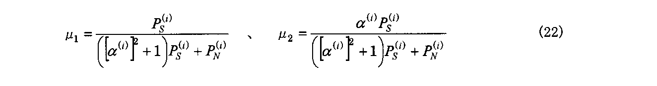
Figure JPOXMLDOC01-appb-M000008
 ここで、このようにして求まる推定値est(S(i)(k))の電力Pest(S) (i)が、数式(18)の両辺を二乗して求まる次の式
  Pest(S) (i)=(μ1+α(i)μ22S (i)+(μ1 2+μ2 2)PN (i)  (23)
を満たす必要があるため、この式から推定値を次式のようにスケーリングする。なお、est′(A)はAの推定値をスケーリングしたものを表す。
Here, the power P est (S) (i) of the estimated value est (S (i) (k)) obtained in this way is obtained by squaring both sides of the equation (18), and the following equation P est (S ) (i) = (μ 1 + α (i) μ 2 ) 2 P S (i) + (μ 1 2 + μ 2 2 ) P N (i) (23)
Therefore, the estimated value is scaled as follows from this equation. Note that est ′ (A) represents a scaled estimate of A.
Figure JPOXMLDOC01-appb-M000009
 そして、i番目の線スペクトルにおける左右チャネルの無相関信号NL (i)(k)、NR (i)(k)に対する推定値est(NL (i)(k))、est(NR (i)(k))はそれぞれ、
  est(NL (i)(k))=μ3L (i)(k)+μ4R (i)(k)  (25)
  est(NR (i)(k))=μ5L (i)(k)+μ6R (i)(k)  (26)
とおくことにより、上述の求め方と同様にして、媒介変数μ3~μ6は、
The estimated values est (N L (i) (k)) and est (N R ) for the left and right channel uncorrelated signals N L (i) (k) and N R (i) (k) in the i-th line spectrum. (i) (k))
est (N L (i) (k)) = μ 3 X L (i) (k) + μ 4 X R (i) (k) (25)
est (N R (i) (k)) = μ 5 X L (i) (k) + μ 6 X R (i) (k) (26)
Thus, in the same way as the above calculation, the parameters μ 3 to μ 6 are
Figure JPOXMLDOC01-appb-M000010
と求めることができる。このようにして求めた推定値est(NL (i)(k))、est(NR (i)(k))も上述と同様に、次の式によってそれぞれスケーリングする。 It can be asked. The estimated values est (N L (i) (k)) and est (N R (i) (k)) obtained in this way are also scaled by the following equations, as described above.
Figure JPOXMLDOC01-appb-M000011
 数式(22)、(27)、(28)で示した各媒介変数μ1~μ6及び数式(24)、(29)、(30)で示したスケーリングの係数が、ステップS6で求める変換係数に該当する。そして、ステップS7では、これらの変換係数を用いた演算(数式(18)、(25)、(26))により推定することで、相関信号と無相関信号(右チャネルの無相関信号、左チャネルの無相関信号)とを分離抽出する。 The respective transformation variables μ 1 to μ 6 represented by the mathematical expressions (22), (27), and (28) and the scaling coefficients represented by the mathematical expressions (24), (29), and (30) are converted coefficients obtained in step S6. It corresponds to. In step S7, the correlation signal and the non-correlated signal (the uncorrelated signal of the right channel, the uncorrelated signal of the left channel) And uncorrelated signals).
 次に、仮想音源への割り当て処理を行う(ステップS8)。本発明では、後述するように低周波数域を抜き取り(抽出して)、その低周波数域については別途処理するが、ここではまず、周波数域に拘わらない仮想音源への割り当て処理について説明する。 Next, the assignment process to the virtual sound source is performed (step S8). In the present invention, as described later, a low frequency region is extracted (extracted), and the low frequency region is separately processed. Here, first, allocation processing to a virtual sound source regardless of the frequency region will be described.
 まず、この割り当て処理では前処理として、線スペクトル毎に推定した相関信号によって生成される合成音像の方向を推定する。この推定処理について、図13~図15に基づき説明する。図13は、受聴者と左右のスピーカと合成音像との位置関係の例を説明するための模式図、図14は、波面合成再生方式で使用するスピーカ群と仮想音源との位置関係の例を説明するための模式図、図15は、図14の仮想音源と受聴者及び合成音像との位置関係の例を説明するための模式図である。 First, in this allocation process, as a pre-process, the direction of the synthesized sound image generated by the correlation signal estimated for each line spectrum is estimated. This estimation process will be described with reference to FIGS. FIG. 13 is a schematic diagram for explaining an example of the positional relationship between the listener, the left and right speakers, and the synthesized sound image, and FIG. 14 shows an example of the positional relationship between the speaker group used in the wavefront synthesis reproduction method and the virtual sound source. FIG. 15 is a schematic diagram for explaining an example of the positional relationship between the virtual sound source of FIG. 14, the listener, and the synthesized sound image.
 いま、図13に示す位置関係130のように、受聴者から左右のスピーカ131L,131Rの中点に引いた線と、同じく受聴者133からいずれかのスピーカ131L/131Rの中心まで引いた線がなす見開き角をθ0、受聴者133から推定合成音像132の位置まで引いた線がなす見開き角をθとする。ここで、左右のスピーカ131L,131Rから同じ音声信号を、音圧バランスを変えて出力した場合、その出力音声によって生じる合成音像132の方向は、音圧バランスを表す前述のパラメータαを用いて次の式で近似できることが一般的に知られている(以下、立体音響におけるサインの法則と呼ぶ)。 Now, as in the positional relationship 130 shown in FIG. 13, a line drawn from the listener to the midpoint of the left and right speakers 131L and 131R and a line drawn from the listener 133 to the center of one of the speakers 131L / 131R are as follows. The spread angle formed is θ 0 , and the spread angle formed by a line drawn from the listener 133 to the position of the estimated synthesized sound image 132 is θ. Here, when the same audio signal is output from the left and right speakers 131L and 131R while changing the sound pressure balance, the direction of the synthesized sound image 132 generated by the output sound is the following using the parameter α representing the sound pressure balance. It is generally known that the following equation can be approximated (hereinafter referred to as the sign law in stereophonic sound).
Figure JPOXMLDOC01-appb-M000012
 ここで、2chステレオの音声信号を波面合成再生方式で再生できるようにするために、図8に示す音声信号分離抽出部81が2chの信号を複数チャネルの信号に変換する。例えば変換後のチャネル数を5つとした場合、それを図14で示す位置関係140のように、波面合成再生方式における仮想音源142a~142eと見做し、スピーカ群(スピーカアレイ)141の後方に配置する。なお、仮想音源142a~142eにおける隣り合う仮想音源との間隔は均等とする。したがって、ここでの変換は、2chの音声信号を仮想音源数の音声信号に変換することになる。既に説明したように、音声信号分離抽出部81は、まず2chの音声信号を、線スペクトル毎に1つの相関信号と2つの無相関信号に分離する。音声信号分離抽出部81では、さらにそれらの信号をどのように仮想音源数の仮想音源(ここでは5つの仮想音源)に割り当てるかを事前に決めておかなければならない。なお、割り当ての方法については複数の方法の中からユーザ設定可能にしておいてもよいし、仮想音源数に応じて選択可能な方法を変えてユーザに提示するようにしてもよい。 Here, in order to be able to reproduce the 2ch stereo audio signal by the wavefront synthesis reproduction method, the audio signal separation and extraction unit 81 shown in FIG. 8 converts the 2ch signal into a signal of a plurality of channels. For example, when the number of channels after conversion is five, it is regarded as virtual sound sources 142a to 142e in the wavefront synthesis reproduction system as shown in the positional relationship 140 shown in FIG. 14, and behind the speaker group (speaker array) 141. Deploy. Note that the virtual sound sources 142a to 142e are equally spaced from adjacent virtual sound sources. Therefore, the conversion here converts the audio signal of 2ch into the audio signal of the number of virtual sound sources. As already described, the audio signal separation and extraction unit 81 first separates the 2ch audio signal into one correlation signal and two uncorrelated signals for each line spectrum. In the audio signal separation / extraction unit 81, it is necessary to determine in advance how to allocate those signals to the virtual sound sources of the number of virtual sound sources (here, five virtual sound sources). The assignment method may be user-configurable from a plurality of methods, or may be presented to the user by changing the selectable method according to the number of virtual sound sources.
 割り当て方法の1つの例として、次のような方法を採る。それは、まず、左右の無相関信号については、5つの仮想音源の両端(仮想音源142a,142e)にそれぞれ割り当てる。次に、相関信号によって生じる合成音像については、5つのうちの隣接する2つの仮想音源に割り当てる。隣接するどの2つの仮想音源に割り当てるかについては、まず、前提として、相関信号によって生じる合成音像が5つの仮想音源の両端(仮想音源142a,142e)より内側になるものとし、すなわち、2chステレオ再生時の2つのスピーカによってなす見開き角内におさまるように5つの仮想音源142a~142eを配置するものとする。そして、合成音像の推定方向から、その合成音像を挟むような隣接する2つの仮想音源を決定し、その2つの仮想音源への音圧バランスの割り当てを調整して、その2つの仮想音源によって合成音像を生じさせるように再生する、という割り当て方法を採る。 The following method is adopted as an example of the allocation method. First, the left and right uncorrelated signals are assigned to both ends ( virtual sound sources 142a and 142e) of the five virtual sound sources, respectively. Next, the synthesized sound image generated by the correlation signal is assigned to two adjacent virtual sound sources out of the five. Regarding which two virtual sound sources are adjacent to each other, first, as a premise, the synthesized sound image generated by the correlation signal is assumed to be inside both ends ( virtual sound sources 142a and 142e) of the five virtual sound sources, that is, 2ch stereo reproduction. Assume that five virtual sound sources 142a to 142e are arranged so as to fall within a spread angle formed by two speakers at the time. Then, two adjacent virtual sound sources that sandwich the synthesized sound image are determined from the estimated direction of the synthesized sound image, and the allocation of the sound pressure balance to the two virtual sound sources is adjusted, and the two virtual sound sources are synthesized. An allocation method is adopted in which reproduction is performed so as to generate a sound image.
 そこで、図15で示す位置関係150のように、受聴者153から両端の仮想音源142a,142eの中点に引いた線と、端の仮想音源142eに引いた線とがなす見開き角をθ0、受聴者153から合成音像151に引いた線とがなす見開き角をθとする。さらに、受聴者153から合成音像151を挟む2つの仮想音源142c,142dの中点に引いた線と、受聴者153から両端の仮想音源142a,142eの中点に引いた線(受聴者153から仮想音源142cに引いた線)とがなす見開き角をφ0、受聴者153から合成音像151に引いた線とがなす見開き角をφとする。ここで、φ0は正の実数である。数式(31)で説明したようにして方向を推定した図13の合成音像132(図15における合成音像151に対応)を、これらの変数を用いて仮想音源に割り当てる方法について説明する。 Therefore, as in the positional relationship 150 shown in FIG. 15, the spread angle formed by the line drawn from the listener 153 to the midpoint of the virtual sound sources 142a and 142e at both ends and the line drawn to the virtual sound source 142e at the end is θ 0. A spread angle formed by a line drawn from the listener 153 to the synthesized sound image 151 is defined as θ. Furthermore, a line drawn from the listener 153 to the midpoint of the two virtual sound sources 142c and 142d sandwiching the synthesized sound image 151 and a line drawn from the listener 153 to the midpoint of the virtual sound sources 142a and 142e at both ends (from the listener 153). The spread angle formed by the line drawn by the virtual sound source 142c) is φ 0 , and the spread angle formed by the line drawn by the listener 153 on the synthesized sound image 151 is φ. Here, φ 0 is a positive real number. A method of assigning the synthesized sound image 132 in FIG. 13 (corresponding to the synthesized sound image 151 in FIG. 15) whose direction has been estimated as described in Equation (31) to the virtual sound source using these variables will be described.
 まず、i番目の合成音像の方向θ(i)が数式(31)によって推定され、例えばθ(i)=π/15[rad]であったとする。そして、仮想音源が5つの場合、図15に示すように合成音像151は左から数えて3番目の仮想音源142cと4番目の仮想音源142dの間に位置することになる。また、仮想音源が5つである場合、3番目の仮想音源142cと4番目の仮想音源142dの間について、三角関数を用いた単純な幾何的計算により、φ0≒0.121[rad]となり、i番目の線スペクトルにおけるφをφ(i)とすると、φ(i)=θ(i)-φ0≒0.088[rad]となる。このようにして、各線スペクトルにおける相関信号によって生じる合成音像の方向を、それを挟む2つの仮想音源の方向からの相対的な角度で表す。そして上述したように、その2つの仮想音源142c,142dでその合成音像を生じさせることを考える。そのためには、2つの仮想音源142c,142dからの出力音声信号の音圧バランスを調整すればよく、その調整方法については、再び数式(31)として利用した立体音響におけるサインの法則を用いる。 First, it is assumed that the direction θ (i) of the i-th synthesized sound image is estimated by Expression (31), and for example, θ (i) = π / 15 [rad]. When there are five virtual sound sources, the synthesized sound image 151 is positioned between the third virtual sound source 142c and the fourth virtual sound source 142d as counted from the left as shown in FIG. When there are five virtual sound sources, φ 0 ≈0.11 [rad] is obtained by simple geometric calculation using a trigonometric function between the third virtual sound source 142c and the fourth virtual sound source 142d. When φ in the i-th line spectrum is φ (i) , φ (i) = θ (i) −φ 0 ≈0.088 [rad]. In this way, the direction of the synthesized sound image generated by the correlation signal in each line spectrum is represented by a relative angle from the directions of the two virtual sound sources sandwiching the synthetic sound image. Then, as described above, it is considered that the synthesized sound image is generated by the two virtual sound sources 142c and 142d. For that purpose, the sound pressure balance of the output audio signals from the two virtual sound sources 142c and 142d may be adjusted, and as the adjustment method, the sign law in the stereophonic sound used again as Equation (31) is used.
 ここで、i番目の線スペクトルにおける相関信号によって生じる合成音像を挟む2つの仮想音源142c,142dのうち、3番目の仮想音源142cに対するスケーリング係数をg1、4番目の仮想音源142dに対するスケーリング係数をg2とすると、3番目の仮想音源142cからはg1・est′(S(i)(k))、4番目の仮想音源142dからはg2・est′(S(i)(k))の音声信号を出力することになる。そして、g1、g2は立体音響におけるサインの法則により、 Here, of the two virtual sound sources 142c and 142d sandwiching the synthesized sound image generated by the correlation signal in the i-th line spectrum, the scaling coefficient for the third virtual sound source 142c is g 1 , and the scaling coefficient for the fourth virtual sound source 142d is When g 2, g 1 · est from the third virtual sound source 142c '(S (i) ( k)), from the fourth virtual source 142d g 2 · est' (S (i) (k)) The audio signal is output. And g 1 and g 2 are due to the sign law in stereophonic sound,
Figure JPOXMLDOC01-appb-M000013
を満たせばよい。 Should be satisfied.
 一方、3番目の仮想音源142cと4番目の仮想音源142dからの電力の合計が、元の2chステレオの相関信号の電力と等しくなるようにg1、g2を正規化すると、
  g1 2+g2 2=1+[α(i)2              (33)
となる。
On the other hand, when g 1 and g 2 are normalized so that the total power from the third virtual sound source 142c and the fourth virtual sound source 142d is equal to the power of the original 2ch stereo correlation signal,
g 1 2 + g 2 2 = 1 + [α (i) ] 2 (33)
It becomes.
 これらを連立させることで、 By combining these,
Figure JPOXMLDOC01-appb-M000014
と求められる。この数式(34)に上述のφ(i)、φ0を代入することによって、g1、g2を算出する。このようにして算出したスケーリング係数に基づき、上述したように3番目の仮想音源142cにはg1・est′(S(i)(k))の音声信号を、4番目の仮想音源142dからはg2・est′(S(i)(k))の音声信号を割り当てる。そして、これも上述したように、無相関信号は両端の仮想音源142a,142eに割り当てられる。すなわち、1番目の仮想音源142aにはest′(NL (i)(k))を、5番目の仮想音源142eにはest′(NR (i)(k))を割り当てる。 Is required. By substituting the aforementioned φ (i) and φ 0 into the mathematical formula (34), g 1 and g 2 are calculated. Based on the scaling coefficient thus calculated, the audio signal of g 1 · est ′ (S (i) (k)) is transmitted from the fourth virtual sound source 142d to the third virtual sound source 142c as described above. The audio signal of g 2 · est ′ (S (i) (k)) is assigned. As described above, the uncorrelated signal is assigned to the virtual sound sources 142a and 142e at both ends. In other words, 'the (N L (i) (k )), the 5 th virtual source 142e est' est is the first virtual sound source 142a assigns the (N R (i) (k )).
 この例とは異なり、もし合成音像の推定方向が1番目と2番目の仮想音源の間であった場合には、1番目の仮想音源にはg1・est′(S(i)(k))とest′(NL (i)(k))の両方が割り当てられることになる。また、もし合成音像の推定方向が4番目と5番目の仮想音源の間であった場合には、5番目の仮想音源にはg2・est′(S(i)(k))とest′(NR (i)(k))の両方が割り当てられることになる。 Unlike this example, if the estimated direction of the synthesized sound image is between the first and second virtual sound sources, g 1 · est ′ (S (i) (k) ) And est ′ (N L (i) (k)) will be assigned. Also, if the estimated direction of the synthesized sound image is between the fourth and fifth virtual sound sources, the second virtual sound source has g 2 · est ′ (S (i) (k)) and est ′. Both (N R (i) (k)) will be assigned.
 以上のようにして、ステップS8における、i番目の線スペクトルについての左右チャネルの相関信号と無相関信号の割り当てが行われる。これをステップS4a,S4bのループにより全ての線スペクトルについて行う。例えば、256点の離散フーリエ変換を行った場合は1~127番目の線スペクトルまで、512点の離散フーリエ変換を行った場合は1~255番目の線スペクトルまで、セグメントの全点(1024点)について離散フーリエ変換を行った場合は1~511番目の線スペクトルまで、となる。その結果、仮想音源の数をJとすると、各仮想音源(出力チャネル)に対する周波数領域の出力音声信号Y1(k),・・・,YJ(k)が求まる。 As described above, the left and right channel correlation signals and uncorrelated signals are assigned to the i-th line spectrum in step S8. This is performed for all line spectra by the loop of steps S4a and S4b. For example, if 256 discrete Fourier transforms are performed, the first to 127th line spectrum up to 512 points. If 512 discrete Fourier transforms are performed, all the segment points up to 1st to 255th line spectrum (1024 points). When the discrete Fourier transform is performed for, the first to 511th line spectra are obtained. As a result, if the number of virtual sound sources is J, output audio signals Y 1 (k),..., Y J (k) in the frequency domain for each virtual sound source (output channel) are obtained.
 以上のように、本発明に係る音声信号再生装置は、マルチチャネルの入力音声信号から得た2つのチャネルの音声信号のそれぞれについて、離散フーリエ変換を施す変換部と、変換部で離散フーリエ変換後の2つのチャネルの音声信号について、直流成分を無視して相関信号を抽出する相関信号抽出部とを備える。この変換部と相関信号抽出部は、図8における音声信号分離抽出部81に含まれる。 As described above, the audio signal reproduction device according to the present invention includes a conversion unit that performs discrete Fourier transform on each of two-channel audio signals obtained from a multi-channel input audio signal, and a discrete Fourier transform performed by the conversion unit. And a correlation signal extraction unit that extracts a correlation signal while ignoring a direct current component. The conversion unit and the correlation signal extraction unit are included in the audio signal separation extraction unit 81 in FIG.
 そして、本発明では、その主たる特徴として、ここでさらに、少ない数のスピーカや小口径のスピーカを使用した際の、低周波数域の音圧の減少を補うための処理を行う。そのために、まず上記の相関信号抽出部が、抽出した相関信号S(k)からさらに所定周波数flowより低い周波数の相関信号を抜き取る(抽出する)。抜き取った相関信号は、低周波数域の音声信号であり、以下、YLFE(k)で表す。その方法について図16及び図17を参照しながら説明する。 In the present invention, as a main feature, a process for compensating for a decrease in sound pressure in the low frequency range when a small number of speakers or small-diameter speakers are used is performed. For this purpose, first, the correlation signal extraction unit extracts (extracts) a correlation signal having a frequency lower than the predetermined frequency f low from the extracted correlation signal S (k). The extracted correlation signal is an audio signal in a low frequency range, and is represented by Y LFE (k) below. The method will be described with reference to FIGS.
 図16は、図8の音声信号処理部における音声信号処理の一例を説明するための模式図で、図17は、図16の音声信号処理における低周波数域を抜き取るためのローパスフィルタの一例を説明するための図である。 16 is a schematic diagram for explaining an example of the audio signal processing in the audio signal processing unit of FIG. 8, and FIG. 17 is an example of a low-pass filter for extracting a low frequency region in the audio signal processing of FIG. It is a figure for doing.
 2つの波形161,162は、2チャネルのうちそれぞれ左チャネル、右チャネルの入力音声波形を示している。上述した処理により、これらの信号から相関信号S(k)164、左無相関信号NL(k)163、及び右無相関信号NR(k)165を抽出し、スピーカ群の後方に配置された5つの仮想音源166a~166eに、前述したような方法で割り当てる。なお、符号163,164,165は、線スペクトルの周波数fに対する振幅スペクトル(強度|f|)を指している。 Two waveforms 161 and 162 indicate the input sound waveforms of the left channel and the right channel, respectively, of the two channels. Through the above-described processing, the correlation signal S (k) 164, the left uncorrelated signal N L (k) 163, and the right uncorrelated signal N R (k) 165 are extracted from these signals and arranged behind the speaker group. The five virtual sound sources 166a to 166e are assigned by the method described above. Reference numerals 163, 164, and 165 denote amplitude spectra (intensities | f |) with respect to the frequency f of the line spectrum.
 本発明では、5つの仮想音源166a~166eへの割り当てに先立ち、相関信号S(k)の低周波数域に含まれる線スペクトルだけを抜き取ることによって、低周波数域の音声信号YLFE(k)だけを抽出しておく。この際、低周波数の範囲は、例えば図17で示すようなローパスフィルタ170によって定義する。ここで、fLTは係数の遷移開始の周波数、fUTは遷移終了の周波数であり上記所定周波数flowに該当する。上記所定周波数としては、例えばflow=150Hzなどに規定しておくなどすればよい。 In the present invention, prior to assignment to the five virtual sound sources 166a to 166e, only the line spectrum included in the low frequency region of the correlation signal S (k) is extracted, so that only the audio signal Y LFE (k) in the low frequency region is obtained. To extract. At this time, the low frequency range is defined by a low-pass filter 170 as shown in FIG. Here, f LT is a coefficient transition start frequency, and f UT is a transition end frequency, which corresponds to the predetermined frequency f low . The predetermined frequency may be defined as f low = 150 Hz, for example.
 また、ローパスフィルタ170では、fLTからfUTの間の周波数については抜き取る際に乗算する係数を1から徐々に少なくしている。ここでは線形的に少なくしているが、これに限らずどのように係数を遷移させてもよい。あるいは遷移範囲を無くし、fLT以下の線スペクトルのみを抜き取ってもよい(この場合にはfLTが上記の所定周波数flowに該当することになる)。 In the low-pass filter 170, the coefficient to be multiplied when extracting the frequency between f LT and f UT is gradually decreased from 1. Although the number is linearly reduced here, the present invention is not limited to this, and the coefficient may be changed in any way. Alternatively, the transition range may be eliminated, and only the line spectrum below f LT may be extracted (in this case, f LT corresponds to the predetermined frequency f low ).
 そして、相関信号S(k)164から低周波数域の音声信号YLFE(k)を抜き取った後の相関信号と、左無相関信号NL(k)163及び右無相関信号NR(k)165を5つの仮想音源166a~166eに割り当てる。割り当ての際には、左無相関信号NL(k)163を最も左側の仮想音源166aに割り当て、右無相関信号NR(k)165を最も右側(後述の仮想音源167を除く最も右側)の仮想音源166eに割り当てる。 Then, the correlation signal after extracting the low-frequency audio signal Y LFE (k) from the correlation signal S (k) 164, the left uncorrelated signal N L (k) 163, and the right uncorrelated signal N R (k) 165 is assigned to five virtual sound sources 166a to 166e. At the time of assignment, the left uncorrelated signal N L (k) 163 is assigned to the leftmost virtual sound source 166a, and the right uncorrelated signal N R (k) 165 is located on the rightmost side (the rightmost side excluding a virtual sound source 167 described later). Assigned to the virtual sound source 166e.
 また、相関信号S(k)164からの抜き取りにより作成した低周波数域の音声信号YLFE(k)を、例えば、5つの仮想音源166a~166eとは別の1つの仮想音源167に割り当てる。仮想音源166a~166eはスピーカ群に対してその後方に均等に配置されるようにし、仮想音源167はその同列の外側に配置されるようにすればよい。この仮想音源167に割り当てられた低周波数域の音声信号YLFE(k)や、仮想音源166a~166eに割り当てられた残りの音声信号は、スピーカ群(スピーカアレイ)から出力されることになる。 In addition, the low-frequency audio signal Y LFE (k) created by sampling from the correlation signal S (k) 164 is assigned to, for example, one virtual sound source 167 different from the five virtual sound sources 166a to 166e. The virtual sound sources 166a to 166e may be arranged evenly behind the speaker group, and the virtual sound source 167 may be arranged outside the same row. The low-frequency audio signal Y LFE (k) assigned to the virtual sound source 167 and the remaining audio signals assigned to the virtual sound sources 166a to 166e are output from the speaker group (speaker array).
 ここで、低周波数域の音声信号YLFE(k)を割り当てた仮想音源167と、他の周波数域の相関信号及び左右の無相関信号を割り当てた他の仮想音源166a~166eとで、仮想音源の再生方法(波面の合成方法)を異ならせる。より具体的には、他の仮想音源166a~166eについては、その仮想音源のx座標(水平方向位置)と距離が近いx座標を持つ出力スピーカほどゲインを大きくし、音のタイミングを早く出力するが、抜き取りによって作成された仮想音源167については、ゲインを全て等しくし、出力タイミングのみ、前述と同様に出力させる。これにより、他の仮想音源166a~166eについては、仮想音源からx座標の距離が遠いスピーカでは出力が小さくなるため、その出力性能を生かしきることができないものの、抜き取り用の仮想音源167では、全てのスピーカから大きい音が出力されるため、トータルの音圧が大きくなる。そして、その場合でも、タイミングを制御して波面を合成するので、音像は少しぼやけるものの、音像定位をさせたまま、音圧を大きくすることができる。このような処理により、低周波数域の音が音圧不足となることを防ぐことができる。 Here, the virtual sound source 167 to which the audio signal Y LFE (k) in the low frequency range is assigned and the virtual sound sources 166a to 166e to which the correlation signal in the other frequency range and the left and right uncorrelated signals are assigned. Different playback methods (wavefront synthesis methods). More specifically, for the other virtual sound sources 166a to 166e, the gain of the output speaker having an x coordinate closer to the x coordinate (horizontal position) of the virtual sound source is increased, and the sound timing is output earlier. However, for the virtual sound source 167 created by sampling, all gains are made equal, and only the output timing is output in the same manner as described above. As a result, for the other virtual sound sources 166a to 166e, the output is small in a speaker whose x coordinate is far from the virtual sound source, and thus the output performance cannot be fully utilized. Since a loud sound is output from the speaker, the total sound pressure increases. Even in this case, since the wavefront is synthesized by controlling the timing, the sound pressure can be increased while the sound image is localized, although the sound image is slightly blurred. Such processing can prevent the sound in the low frequency range from becoming insufficient in sound pressure.
 このように、低周波数域の音声信号YLFE(k)はスピーカ群から出力されることになるが、合成波面を形成するように出力される。合成波面は仮想音源の割り当てにより形成することが好ましい。つまり、本発明に係る音声信号再生装置は次のような出力部を備えることが好ましい。この出力部は、上記の相関信号抽出部で抜き取られた相関信号を、1つの仮想音源に割り当てて波面合成再生方式でスピーカ群の一部または全部から出力する。なお、スピーカ群の一部または全部としたのは、上記の相関信号抽出部で抜き取られた相関信号が示す音像によっては、スピーカ群の全てを使用する場合と一部のみを使用する場合があるためである。 Thus, the audio signal Y LFE (k) in the low frequency range is output from the speaker group, but is output so as to form a composite wavefront. The composite wavefront is preferably formed by assigning virtual sound sources. That is, the audio signal reproduction device according to the present invention preferably includes the following output unit. The output unit assigns the correlation signal extracted by the correlation signal extraction unit to one virtual sound source, and outputs the correlation signal from a part or all of the speaker group by the wavefront synthesis reproduction method. Note that some or all of the loudspeaker groups may be used when all or some of the loudspeaker groups are used depending on the sound image indicated by the correlation signal extracted by the correlation signal extraction unit. Because.
 ここで、上記の出力部は、図7,図8における音声出力信号生成部82、図7におけるD/Aコンバータ74、及び増幅器75(及びスピーカ群76)が該当する。但し、上述したように波面合成再生処理の一部は音声信号分離抽出部81で担ってもよい。 Here, the output unit corresponds to the audio output signal generation unit 82 in FIGS. 7 and 8, the D / A converter 74 and the amplifier 75 (and the speaker group 76) in FIG. However, as described above, part of the wavefront synthesis reproduction processing may be performed by the audio signal separation / extraction unit 81.
 上記の出力部は、抜き取った低周波数域の信号を1つの仮想音源としてスピーカ群から再生するものであるが、そのような合成波として実際にスピーカ群から出力するためには、出力先となる隣り合うスピーカ同士が合成波面を生成し得る条件を満たす必要がある。その条件は、空間サンプリング周波数の定理から、出力対象の隣り合うスピーカ同士の音の出力の時間差が2Δx/cの範囲に入っているといった条件である。 The above output unit reproduces the extracted low-frequency signal from the speaker group as one virtual sound source. However, in order to actually output such a synthesized wave from the speaker group, it becomes an output destination. It is necessary to satisfy a condition that adjacent speakers can generate a composite wavefront. The condition is that, based on the spatial sampling frequency theorem, the time difference in sound output between adjacent speakers to be output is in the range of 2Δx / c.
 ここで、Δxは出力対象の隣り合うスピーカ同士の間隔(出力対象のスピーカ間の中心の間隔)、cは音速とする。例えば、c=340m/sとし、Δxが0.17mのとき、この時間差の値は1msとなる。そして、この値の逆数が、このスピーカ間隔で波面合成が行える上限の周波数(fthとする)となり、この例ではfth=1000Hzとなる。すなわち、隣り合うスピーカから2Δx/c以内の時間差で波面を合成しようとした場合、上限周波数fthより高い音については、波面を合成することができない。逆に言えば、上限周波数fthはスピーカの間隔によって定まり、その逆数が、制限時間の上限値となる。これらの点を考慮すると、上記所定周波数flowは150Hzとして例示したようにこの上限周波数fth(例えば1000Hz)より低い周波数で規定し、相関信号の抽出を行い、且つ上記時間差が2Δx/cの範囲に入るようにしておけば、上記所定周波数flowより低い周波数についてはいずれの周波数であっても波面を合成することができる。 Here, Δx is an interval between adjacent speakers to be output (center interval between speakers to be output), and c is a sound velocity. For example, when c = 340 m / s and Δx is 0.17 m, the value of this time difference is 1 ms. The reciprocal of this value is the upper limit frequency (referred to as f th ) at which wavefront synthesis can be performed at this speaker interval, and in this example, f th = 1000 Hz. That is, when trying to synthesize a wavefront with a time difference within 2Δx / c from adjacent speakers, it is not possible to synthesize a wavefront for a sound higher than the upper limit frequency f th . In other words, the upper limit frequency f th is determined by the speaker interval, and the reciprocal thereof is the upper limit value of the time limit. Considering these points, the predetermined frequency f low is defined as a frequency lower than the upper limit frequency f th (for example, 1000 Hz) as exemplified as 150 Hz, the correlation signal is extracted, and the time difference is 2Δx / c. If the frequency falls within the range, the wavefront can be synthesized at any frequency lower than the predetermined frequency f low .
 換言すれば、本発明における上記の出力部は、抜き取られた相関信号を、出力先の隣り合うスピーカ同士の音の出力の時間差が2Δx/cの範囲に入るように、スピーカ群の一部または全部から出力していると言える。実際には、抜き出した相関信号に対し、出力先の隣り合うスピーカ同士の音の出力の時間差が2Δx/cの範囲に入るように変換を施し、スピーカ群の一部または全部から出力することで、合成波面を形成している。なお、出力先の隣り合うスピーカ同士とは、設けられたスピーカ群において隣り合うスピーカ同士を指す場合に限らず、スピーカ群において隣り合わないスピーカ同士のみが出力先となる場合もあり、その場合には出力先だけを考慮して隣り合うか否かを決めればよい。 In other words, the above-described output unit in the present invention is configured so that the extracted correlation signal is a part of a speaker group or a group of speakers so that the time difference in sound output between adjacent speakers at the output destination falls within a range of 2Δx / c. It can be said that the output is from all. In practice, the extracted correlation signal is converted so that the time difference in sound output between adjacent speakers at the output destination falls within the range of 2Δx / c, and output from a part or all of the speaker group. , Forming a composite wavefront. It should be noted that the speakers adjacent to each other in the output destination are not limited to the case of referring to the speakers adjacent to each other in the provided speaker group, and only the speakers that are not adjacent to each other in the speaker group may be the output destination. Determines whether or not they are adjacent to each other considering only the output destination.
 また、低周波数域の音声信号は、指向性が弱く、信号が回折し易いので、上述のようにして仮想音源167から出力されるようにスピーカ群から出力したとしても、それが四方八方に拡がる。よって、図16を参照して説明した例のように仮想音源167を仮想音源166a~166eと同列に配置する必要はなく、どの位置に配置してもよい。 Further, since the audio signal in the low frequency range has low directivity and the signal is easily diffracted, even if it is output from the speaker group so as to be output from the virtual sound source 167 as described above, it spreads in all directions. . Therefore, unlike the example described with reference to FIG. 16, the virtual sound source 167 need not be arranged in the same row as the virtual sound sources 166a to 166e, and may be arranged at any position.
 また、上述のようにして割り当てる仮想音源の位置は、5つの仮想音源166a~166eと別にする必要は必ずしもない。図18を参照して、図16の音声信号処理において割り当てる低周波数域用の仮想音源の他の位置の例を説明する。割り当てる仮想音源の位置は、例えば、図18に示す位置関係180のように、低周波数域用の仮想音源183を、5つの仮想音源182a~182e(それぞれ上述の5つの仮想音源166a~166eに対応)のうち真ん中に配置された仮想音源182cの位置と同じ位置に設定してもよい。この仮想音源183に割り当てられた低周波数域の音声信号YLFE(k)や、仮想音源182a~182eに割り当てられた残りの音声信号は、スピーカ群(スピーカアレイ)181から出力されることになる。 Further, the position of the virtual sound source assigned as described above is not necessarily different from the five virtual sound sources 166a to 166e. With reference to FIG. 18, an example of another position of the virtual sound source for the low frequency range assigned in the audio signal processing of FIG. 16 will be described. The positions of the virtual sound sources to be assigned correspond to the five virtual sound sources 182a to 182e (the above-mentioned five virtual sound sources 166a to 166e, respectively), for example, as in the positional relationship 180 shown in FIG. ) May be set to the same position as the position of the virtual sound source 182c arranged in the middle. The low-frequency audio signal Y LFE (k) assigned to the virtual sound source 183 and the remaining audio signals assigned to the virtual sound sources 182a to 182e are output from the speaker group (speaker array) 181. .
 以上、本発明では、波面合成再生方式での再生によりどの聴取位置からでも忠実に音像を再現することができるだけでなく、上述のように相関信号について周波数域に応じて異なる処理を施すことにより、スピーカアレイ(スピーカユニット)の特性に応じて、非常に高い精度で目的の低周波数域だけを抽出することができ、低周波数域の音が音圧不足となることを防ぐことができる。また、ここで、スピーカユニットの特性とは、各スピーカの特性を指し、例えば同じスピーカを並べたアレイスピーカのみであれば各スピーカに共通の出力周波数特性であり、このようなスピーカアレイに加えてウーファーがあれば、そのウーファーの出力周波数特性も合わせた特性を指す。このような効果は、少ない個数のスピーカや小口径のスピーカ、それに各チャネルが小容量のアンプしか搭載できないなど、低コストの制約下のスピーカ群によって波面合成再生方式で音声信号を再生する場合に特に有益となる。 As described above, in the present invention, not only can the sound image be faithfully reproduced from any listening position by reproduction in the wavefront synthesis reproduction method, but also by performing different processing on the correlation signal according to the frequency range as described above, Depending on the characteristics of the speaker array (speaker unit), it is possible to extract only the target low frequency range with very high accuracy, and it is possible to prevent the sound in the low frequency range from being insufficient in sound pressure. Here, the characteristic of the speaker unit refers to the characteristic of each speaker. For example, if only an array speaker in which the same speakers are arranged is an output frequency characteristic common to each speaker. In addition to such a speaker array, If there is a woofer, it refers to the combined characteristics of the output frequency of the woofer. This effect is effective when audio signals are played back by the wavefront synthesis playback method using a low-cost speaker group such as a small number of speakers, small-diameter speakers, and only a small capacity amplifier for each channel. Especially useful.
 また、このように、それぞれの仮想音源(図16における仮想音源166a~166e、図18における仮想音源182a~182e)の低周波数成分を増圧するのではなく、1つの仮想音源(図16における仮想音源167、図18における仮想音源183)に割り当てることにより、低周波数成分が複数の仮想音源から出力されることによる干渉を防ぐことができる。 In this way, instead of increasing the low frequency components of the respective virtual sound sources (virtual sound sources 166a to 166e in FIG. 16, virtual sound sources 182a to 182e in FIG. 18), one virtual sound source (virtual sound source in FIG. 16) is used. 167 and the virtual sound source 183 in FIG. 18 can prevent interference due to low frequency components being output from a plurality of virtual sound sources.
 次に、図9のステップS1~S8により得られた各出力チャネルに対する処理について説明する。各出力チャネルについては、次のようなステップS10~S12の処理を実行する(ステップS9a,S9b)。以下、ステップS10~S12の処理について説明する。 Next, processing for each output channel obtained in steps S1 to S8 in FIG. 9 will be described. For each output channel, the following steps S10 to S12 are executed (steps S9a and S9b). Hereinafter, the processing of steps S10 to S12 will be described.
 まず、各出力チャネルを離散フーリエ逆変換することによって、時間領域の出力音声信号y′J(m)を求める(ステップS10)。ここで、DFT-1は離散フーリエ逆変換を表す。 First, the output speech signal y ′ J (m) in the time domain is obtained by performing inverse discrete Fourier transform on each output channel (step S10). Here, DFT −1 represents discrete Fourier inverse transform.
  y′J(m)=DFT-1(YJ(k))  (1≦j≦J)   (35)
 ここで、数式(3)で説明したように、離散フーリエ変換した信号は、窓関数乗算後の信号であったため、逆変換して得られた信号y′J(m)も窓関数が乗算された状態となっている。窓関数は数式(1)に示すような関数であり、読み込みは1/4セグメント長ずつずらしながら行ったため、前述した通り、1つ前に処理したセグメントの先頭から1/4セグメント長ずつずらしながら出力バッファに加算していくことにより変換後のデータを得る。
y ′ J (m) = DFT −1 (Y J (k)) (1 ≦ j ≦ J) (35)
Here, as described in Equation (3), since the signal subjected to the discrete Fourier transform is a signal after the window function multiplication, the signal y ′ J (m) obtained by the inverse transformation is also multiplied by the window function. It is in the state. The window function is a function as shown in Formula (1), and reading is performed while shifting by a ¼ segment length. Therefore, as described above, the window function is shifted by a ¼ segment length from the head of the previous processed segment. The converted data is obtained by adding to the output buffer.
 ここで、前述したように離散フーリエ変換を行う前にHann窓を演算している。Hann窓の両端点の値は0であるため、もし離散フーリエ変換後、どのスペクトル成分も値を変更せず、再び離散フーリエ逆変換を行えば、そのセグメントの両端点は0となり、セグメント間の不連続点は発生しない。しかし実際は、離散フーリエ変換後の周波数領域において、上述したように各スペクトル成分を変更するため、離散フーリエ逆変換後のセグメントの両端点は0とならず、セグメント間の不連続点が発生する。 Here, as described above, the Hann window is calculated before performing the discrete Fourier transform. Since the values of the end points of the Hann window are 0, if the discrete Fourier transform does not change any spectral components and the inverse discrete Fourier transform is performed again, the end points of the segment will be 0, There are no discontinuities. However, in actuality, in the frequency domain after the discrete Fourier transform, each spectral component is changed as described above. Therefore, both end points of the segment after the inverse discrete Fourier transform are not 0, and discontinuous points between the segments are generated.
 したがって、その両端点を0にするため、前述したように、再度Hann窓を演算する。これにより、両端点が0となること、つまり不連続点が生じないことが保証される。より具体的には、離散フーリエ逆変換後の音声信号(つまり、相関信号またはそれから生成された音声信号)のうち、処理セグメントの音声信号に対し、再びHann窓関数を乗算し、処理セグメントの長さの1/4だけずらして、前の処理セグメントの音声信号に加算することにより、離散フーリエ逆変換後の音声信号から波形の不連続点を除去する。ここで、前の処理セグメントとは、以前の処理セグメントであって、実際には1/4ずつずらすため、1つ前、2つ前、及び3つ前の処理セグメントを指す。その後は、前述したように、2回目のHann窓関数乗算処理後の処理セグメントに対し、3/2の逆数である2/3を乗じれば、元の波形が完全に復元できる。無論、この2/3の乗算を加算対象の処理セグメントに対して施してから、ずらし及び加算を実行してもよい。また、この2/3を乗算する処理については実行しなくても、振幅が大きくなるだけであるので構わない。 Therefore, in order to set the both end points to 0, the Hann window is calculated again as described above. This ensures that both end points are zero, that is, no discontinuities occur. More specifically, among the audio signals after inverse discrete Fourier transform (that is, the correlation signal or the audio signal generated therefrom), the audio signal of the processing segment is again multiplied by the Hann window function to obtain the length of the processing segment. The waveform discontinuity is removed from the audio signal after the inverse discrete Fourier transform by shifting it by 1/4 and adding it to the audio signal of the previous processing segment. Here, the previous processing segment refers to the previous processing segment, which is actually shifted by ¼, and refers to the previous, second, and third previous processing segments. Thereafter, as described above, the original waveform can be completely restored by multiplying the processing segment after the second Hann window function multiplication process by 2/3, which is the inverse of 3/2. Of course, the shift and addition may be executed after the 2/3 multiplication is performed on the processing segment to be added. Further, the process of multiplying 2/3 does not have to be executed, but only the amplitude is increased.
 なお、例えば、読み込みを半セグメント長ずつずらしながら行った場合には、1つ前に処理したセグメントの先頭から半セグメント長ずつずらしながら出力バッファに加算していくことにより変換後のデータを得ればよく、この場合には上記両端点が0となること(不連続点が生じないこと)が保証されないが、何らかの不連続点除去処理を施せばよい。この場合の不連続点除去処理の詳細については、例えば、2回目の窓関数演算を施さずに特許文献1に記載の不連続点除去処理を採用するなどすればよいが、本発明とは直接関係ないため、その説明を省略する。 For example, when reading is performed while shifting by half segment length, the converted data can be obtained by adding to the output buffer while shifting by half segment length from the head of the previous segment processed. In this case, it is not guaranteed that the both end points become 0 (no discontinuity occurs), but some discontinuity removal processing may be performed. For details of the discontinuous point removal processing in this case, for example, the discontinuous point removal processing described in Patent Document 1 may be adopted without performing the second window function calculation, but directly with the present invention. Since it is not related, the explanation is omitted.
 次に、図19の模式図を参照しながら、図8の音声信号処理部における音声信号処理の他の例を説明する。 Next, another example of the audio signal processing in the audio signal processing unit of FIG. 8 will be described with reference to the schematic diagram of FIG.
 上述の説明では、低周波数域の音声信号YLFE(k)を1つの仮想音源に割り当てて波面合成再生方式によって再生したが、図19に示す位置関係190のように、低周波数域の音声信号YLFE(k)を、スピーカ群191からの合成波が平面波となるように波面合成再生方式で再生させてもよい。このように、上記の出力部は、上記の相関信号抽出部で抜き取られた相関信号を、スピーカ群の一部または全部から平面波として波面合成再生方式で出力してもよい。ここで、図19では、スピーカ群191の並び方向(アレイ方向)に垂直な方向に進む平面波を出力する例を挙げているが、スピーカ群191の並び方向に所定の角度を付けて斜めに進むような平面波を出力することもできる。 In the above description, the audio signal Y LFE (k) in the low frequency range is assigned to one virtual sound source and reproduced by the wavefront synthesis reproduction method. However, as in the positional relationship 190 shown in FIG. Y LFE (k) may be reproduced by the wavefront synthesis reproduction method so that the synthesized wave from the speaker group 191 becomes a plane wave. As described above, the output unit may output the correlation signal extracted by the correlation signal extraction unit as a plane wave from a part or all of the speaker group by the wavefront synthesis reproduction method. Here, FIG. 19 shows an example in which plane waves traveling in a direction perpendicular to the direction in which the speaker groups 191 are arranged (array direction) are output. However, the arrangement proceeds in an oblique manner with a predetermined angle in the direction in which the speaker groups 191 are arranged. Such plane waves can also be output.
 ここで、平面波として出力するためには、(a)平面波は、隣り合うスピーカ同士の遅延を一定間隔で均一に付けた出力タイミングで各スピーカから出力すればよい。なお、図19の例のようにアレイ方向に垂直に進む平面波の場合には、この一定間隔を「0」とすし、隣り合うスピーカ同士の遅延を「0」にした出力タイミングで各スピーカから出力すればよい。また、他の方法として、図19の例のようにアレイ方向に垂直に進む平面波として出力するためには、(b)非低周波数域の音声信号で割り当てのない仮想音源(図16の167)を少なくとも1つを含むような全ての仮想音源(図16の166a~166e,167)から均等に出力するような処理を行ってもよい。上記(b)の応用として、仮想音源の並び方向をスピーカ群の並び方向と平行ではなく角度を付けた方向に設定しておくことで、スピーカ群の並び方向に所定の角度を付けて斜めに進むような平面波を出力することができる。 Here, in order to output as a plane wave, (a) the plane wave may be output from each speaker at an output timing in which delays between adjacent speakers are uniformly provided at a constant interval. In the case of a plane wave that travels perpendicular to the array direction as in the example of FIG. 19, this constant interval is set to “0”, and the delay between adjacent speakers is set to “0”. do it. As another method, in order to output as a plane wave traveling perpendicularly to the array direction as in the example of FIG. 19, (b) a virtual sound source (167 in FIG. 16) that is not assigned with a non-low frequency audio signal May be performed so as to be output equally from all virtual sound sources (166a to 166e, 167 in FIG. 16) including at least one of them. As an application of the above (b), by setting the direction of the virtual sound source to be in an angled direction rather than parallel to the direction of the speaker group, the direction of the speaker group is inclined with a predetermined angle. A traveling plane wave can be output.
 このように平面波として出力する場合にも、合成波を出力していることから、上記の出力部は、抜き取られた相関信号を、出力先の隣り合うスピーカ同士の音の出力の時間差が2Δx/cの範囲に入るように、スピーカ群の一部または全部から出力していると言える。例えば、上記(a),(b)のいずれの場合でも、時間差が2Δx/c以内になるか否かで波面が合成できるか否かは決まる。また、平面波と曲面波との違いというのは、3つ以上並べられたスピーカがどのように遅延を順番につけていくかによって決定される。具体的には、等間隔でつければ図19で例示したような平面波となり、例えば中央から両端に向かって徐々に間隔を拡げていけば図18で例示した曲面と同様の曲面(凸面)となる。このように、2つのスピーカだけでは出力が平面波となるか曲面波となるかは決まらないものの、少なくとも時間差が2Δx/c以内になるか否かで波面が合成できるか否かは決まる。 Even when outputting as a plane wave in this way, since the composite wave is output, the output unit described above uses the extracted correlation signal as a time difference in sound output between adjacent speakers at output destinations of 2Δx / It can be said that the sound is output from part or all of the speaker group so as to fall within the range of c. For example, in both cases (a) and (b), whether or not the wavefront can be synthesized is determined by whether or not the time difference is within 2Δx / c. Also, the difference between a plane wave and a curved wave is determined by how the three or more arranged speakers add delay in order. Specifically, if they are attached at equal intervals, the plane wave as illustrated in FIG. 19 is obtained. For example, if the interval is gradually increased from the center toward both ends, a curved surface (convex surface) similar to the curved surface illustrated in FIG. . Thus, although it is not determined whether the output is a plane wave or a curved wave with only two speakers, whether or not the wavefront can be synthesized is determined by whether or not the time difference is within 2Δx / c.
 低周波数域の音声信号は、指向性が弱く、信号が回折し易いので、このようにして平面波で出力(平面波として再生)したとしても、それが四方八方に拡がるが、中周波数域や高周波数域の音声信号では指向性が強いため、平面波で出力しまうとビームのようにその進行方向にエネルギーが集中し、進行方向以外では音圧が弱くなる。よって、低周波数域の音声信号YLFE(k)を平面波として再生する構成においても、低周波数域の音声信号YLFE(k)を取り除いた後の相関信号と、左右の無相関信号については、平面波として再生せずに、図16を参照して説明した例と同様に仮想音源192a~192eに割り当てて波面合成再生方式によりスピーカ群191から出力する。 Audio signals in the low frequency range are weakly directional and easily diffracted, so even if output in this way as a plane wave (reproduced as a plane wave), it spreads in all directions, but the medium frequency range and high frequency range Since the directivity of the sound signal in the region is strong, if it is output as a plane wave, the energy is concentrated in the traveling direction like a beam, and the sound pressure is weak in other directions. Therefore, also in the configuration of reproducing the low frequency range of the audio signal Y LFE (k) as a plane wave, and the correlation signal after removal of the low-frequency range of the audio signal Y LFE (k), the left and right uncorrelated signals, As in the example described with reference to FIG. 16, the sound waves are assigned to the virtual sound sources 192a to 192e and output from the speaker group 191 by the wavefront synthesis reproduction method without being reproduced as a plane wave.
 このように、図19の例では、低周波数域の音声信号YLFE(k)については仮想音源を割り当てず平面波で出力し、他の周波数域の相関信号及び左右の無相関信号については仮想音源を割り当てて出力するようにし、両者で再生方法(波面の合成方法)を異ならせる。これにより、割り当てた仮想音源については図16を参照した説明と同様に仮想音源からx座標の距離が遠いスピーカでは出力が小さくなるものの、抜き取った低周波数域の音声信号YLFE(k)については、平面波を形成するために全てのスピーカから大きい音が出力されるため、トータルの音圧が大きくなり、低周波数域の音が音圧不足となることを防ぐことができる。 As described above, in the example of FIG. 19, the sound signal Y LFE (k) in the low frequency range is output as a plane wave without assigning a virtual sound source, and the virtual sound source is output for correlated signals in other frequency ranges and left and right uncorrelated signals. Are assigned and output, and the playback method (wavefront synthesis method) differs between the two. As a result, for the assigned virtual sound source, the output is reduced in the speaker whose x-coordinate distance is far from the virtual sound source as in the description with reference to FIG. 16, but the extracted low-frequency audio signal Y LFE (k) is Since a loud sound is output from all the speakers to form a plane wave, the total sound pressure is increased, and it is possible to prevent a sound in a low frequency range from becoming insufficient.
 したがって、図19で説明した例においても、波面合成再生方式での再生によりどの聴取位置からでも忠実に音像を再現することができるだけでなく、上述のように相関信号について周波数域に応じて異なる処理を施すことにより、スピーカアレイ(スピーカユニット)の特性に応じて、非常に高い精度で目的の低周波数域だけを抽出することができ、低周波数域の音が音圧不足となることを防ぐことができる。 Accordingly, in the example described with reference to FIG. 19, not only can the sound image be faithfully reproduced from any listening position by reproduction using the wavefront synthesis reproduction method, but the correlation signal can be processed differently depending on the frequency range as described above. By applying, it is possible to extract only the target low frequency range with very high accuracy according to the characteristics of the speaker array (speaker unit), and to prevent the sound in the low frequency range from becoming insufficient in sound pressure Can do.
 次に、図20の模式図を参照しながら、図8の音声信号処理部における音声信号処理の他の例を説明する。 Next, another example of the audio signal processing in the audio signal processing unit of FIG. 8 will be described with reference to the schematic diagram of FIG.
 平面波としては、例えば図20で例示したように、スピーカ群20の並び方向のあるところから、両端に向かって、均一に遅延を付け、二方向に平面波を作るようにしてもよい。 As the plane wave, for example, as illustrated in FIG. 20, a plane wave may be generated in two directions by uniformly delaying from both of the arrangement direction of the speaker groups 20 toward both ends.
 また、抜き出した相関信号については、1つの仮想音源として出力する例や平面波として出力する例に限らず、次のような出力方法を採用することができる。例えば、非常に低い周波数帯域だけを抜き取るのであれば、極端な例を挙げると、上述の時間差内でランダムに遅延を付けたとしても、聴感上は違和感なく低音を強調することは可能である。よって、抜き取る周波数帯域に依存するが、割合高い周波数までを含むように抜き取りを行うのであれば、図18のような通常の波面合成(曲面波)か、図19のような平面波か、図20のような平面波を生成することが好ましいが、非常に低い周波数帯域だけしか含まないように抜き取るのであれば、上述の時間差内であればどのような遅延の付け方でもよい。その境界は、音の定位が難しくなってくる120Hz辺りが目安となる。つまり、上記所定周波数flowを120Hz辺りより低く設定して抜き出すのであれば、抜き出した相関信号について、時間差2Δx/c以内でランダムに遅延を付けてスピーカ群の一部又は全部から出力することもできる。 The extracted correlation signal is not limited to an example of outputting as a single virtual sound source or an example of outputting as a plane wave, and the following output method can be employed. For example, if only a very low frequency band is extracted, to give an extreme example, even if a delay is randomly added within the above-described time difference, it is possible to enhance the bass without any sense of incongruity. Therefore, depending on the frequency band to be extracted, if the extraction is performed so as to include even a relatively high frequency, the normal wavefront synthesis (curved wave) as shown in FIG. 18, the plane wave as shown in FIG. It is preferable to generate a plane wave such as that described above, but any delay may be applied as long as it is extracted so that only a very low frequency band is included. The boundary is about 120 Hz where sound localization becomes difficult. In other words, if the predetermined frequency f low is set lower than around 120 Hz and extracted, the extracted correlation signal may be output from a part or all of the speaker group with a random delay within a time difference of 2Δx / c. it can.
 次に、本発明の実装について簡単に説明する。本発明は、例えばテレビ装置など映像の伴う装置に利用できる。本発明を適用可能な装置の様々な例について、図21~図23を参照しながら説明する。図21~図23は、それぞれ図7の音声信号再生装置を備えたテレビ装置の構成例を示す図である。なお、図21~図23のいずれにおいても、スピーカアレイとして一列につき5個のスピーカを配列した例を挙げているが、スピーカの数は複数であればよい。 Next, the implementation of the present invention will be briefly described. The present invention can be used for an apparatus accompanied by an image such as a television apparatus. Various examples of apparatuses to which the present invention can be applied will be described with reference to FIGS. FIG. 21 to FIG. 23 are diagrams showing examples of the configuration of a television apparatus provided with the audio signal reproduction device of FIG. In any of FIGS. 21 to 23, an example is shown in which five speakers are arranged in a row as the speaker array, but the number of speakers may be plural.
 本発明に係る音声信号再生装置はテレビ装置に利用できる。テレビ装置におけるこれらの装置の配置は自由に決めればよい。図21で示すテレビ装置210のように、テレビ画面211の上方と下方に、音声信号再生装置におけるスピーカ212a~212eを直線状に並べたスピーカ群212とスピーカ213a~213eを直線状に並べたスピーカ群213とを設けてもよい。図22で示すテレビ装置220のように、テレビ画面221の下方に、音声信号再生装置におけるスピーカ222a~222eを直線状に並べたスピーカ群222を設けてもよい。図23で示すテレビ装置230のように、テレビ画面231の上方に、音声信号再生装置におけるスピーカ232a~232eを直線状に並べたスピーカ群232を設けてもよい。また、図示しないが、多少のコストを犠牲にすれば、音声信号再生装置における透明のフィルム型スピーカを直線状に並べたスピーカ群を、テレビ画面に埋め込むこともできる。 The audio signal reproduction apparatus according to the present invention can be used for a television apparatus. The arrangement of these devices in the television device may be determined freely. Like the television apparatus 210 shown in FIG. 21, the speaker group 212 in which the speakers 212a to 212e in the audio signal reproducing apparatus are arranged in a straight line and the speakers in which the speakers 213a to 213e are arranged in a straight line above and below the television screen 211. A group 213 may be provided. Like the television device 220 shown in FIG. 22, a speaker group 222 in which the speakers 222a to 222e in the audio signal reproducing device are arranged in a straight line may be provided below the television screen 221. Like the television device 230 shown in FIG. 23, a speaker group 232 in which the speakers 232a to 232e in the audio signal reproduction device are arranged in a straight line may be provided above the television screen 231. Although not shown, if some cost is sacrificed, a speaker group in which transparent film type speakers in the audio signal reproducing apparatus are arranged in a straight line can be embedded in the television screen.
 このようにして、アレイスピーカを画面の上下、あるいは上側、あるいは下側に取り付けるなどにより、少ないスピーカ数や小口径のアレイスピーカでも、低周波数域でも音圧の大きい波面合成再生方式の音声信号再生が可能なテレビ装置を実現することができる。 In this way, by mounting the array speakers on the top, bottom, top, or bottom of the screen, sound signals can be reproduced using a wavefront synthesis playback system with a large number of speakers, small-diameter arrays, and high sound pressure even in the low frequency range. Can be realized.
 そのほか、本発明に係る音声信号再生装置は、テレビ台(テレビボード)に埋め込むこともでき、またサウンドバーと呼ばれるテレビ装置の下に置く一体型のスピーカーシステムに埋め込むこともできる。いずれの場合でも音声信号を変換する部分のみをテレビ装置側に設けておくこともできる。その他、本発明に係る音声信号再生装置は、スピーカ群を曲線状に並べたカーオーディオに適用することもできる。 In addition, the audio signal reproduction device according to the present invention can be embedded in a television stand (television board), or can be embedded in an integrated speaker system placed under a television device called a sound bar. In either case, only the part that converts the audio signal can be provided on the television set side. In addition, the audio signal reproduction device according to the present invention can be applied to a car audio in which speaker groups are arranged in a curved line.
 また、図21~図23を参照して説明したようなテレビ装置などの装置に本発明に係る音声信号再生処理を適用した際、受聴者はこの処理(図7や図8の音声信号処理部73における処理)を行うか行わないかについて、装置本体に備えられたボタン操作やあるいはリモートコントローラ操作などでなされたユーザ操作により切り替える切替部を設けることもできる。この変換処理を行わない場合、低周波数域か否かに拘わらず同様の処理を適用し、仮想音源を配置して波面合成再生方式で再生するなどすればよい。 In addition, when the audio signal reproduction process according to the present invention is applied to a device such as a television set as described with reference to FIGS. 21 to 23, the listener performs this process (the audio signal processing unit in FIGS. 7 and 8). It is also possible to provide a switching unit that switches whether or not to perform the processing in (73) by a user operation performed by a button operation or a remote controller operation provided in the apparatus main body. When this conversion processing is not performed, the same processing may be applied regardless of whether the frequency range is low, a virtual sound source is arranged, and reproduction is performed using the wavefront synthesis reproduction method.
 また、本発明で適用可能な波面合成再生方式としては、上述したようにスピーカアレイ(複数のスピーカ)を備えて仮想音源に対する音像としてそれらのスピーカから出力するようにする方式であればよく、非特許文献1に記載のWFS方式の他、人間の音像知覚に関する現象としての先行音効果(ハース効果)を利用した方式など様々な方式が挙げられる。ここで、先行音効果とは、同一の音声を複数の音源から再生し、音源それぞれから聴取者に到達する各音声に小さな時間差がある場合、先行して到達した音声の音源方向に音像が定位する効果を指し示したものである。この効果を利用すれば、仮想音源位置に音像を知覚させることが可能となる。ただし、その効果だけで音像を明確に知覚させることは難しい。ここで、人間は音圧を最も高く感じる方向に音像を知覚するという性質も持ち合わせている。したがって、音声信号再生装置において、上述の先行音効果と、この最大音圧方向知覚の効果とを組み合わせ、これにより、少ない数のスピーカでも仮想音源の方向に音像を知覚させることが可能になる。 In addition, as a wavefront synthesis reproduction method applicable in the present invention, any method may be used as long as it includes a speaker array (a plurality of speakers) and outputs a sound image for a virtual sound source from those speakers. In addition to the WFS method described in Patent Document 1, there are various methods such as a method using a preceding sound effect (Haas effect) as a phenomenon related to human sound image perception. Here, the preceding sound effect means that if the same sound is played from multiple sound sources and each sound reaching the listener from each sound source has a small time difference, the sound image is localized in the sound source direction of the sound that has arrived in advance. It points out the effect to do. If this effect is used, a sound image can be perceived at the virtual sound source position. However, it is difficult to clearly perceive the sound image only by the effect. Here, humans also have the property of perceiving a sound image in the direction in which the sound pressure is felt highest. Therefore, in the audio signal reproducing apparatus, the preceding sound effect described above and the effect of perceiving the maximum sound pressure direction are combined, so that a sound image can be perceived in the direction of the virtual sound source even with a small number of speakers.
 以上、本発明に係る音声信号再生装置が、マルチチャネル再生方式用の音声信号を変換することにより波面合成再生方式用の音声信号を生成して再生する例を挙げた。しかし、本発明に係る音声信号再生装置は、マルチチャネル再生方式用の音声信号に限らず、例えば波面合成再生方式用の音声信号を入力音声信号として、それを、上述したように低周波数域を抜き取って別処理するような波面合成再生方式用の音声信号に変換して再生するように構成することもできる。 As described above, the example in which the audio signal reproduction device according to the present invention generates and reproduces the audio signal for the wavefront synthesis reproduction method by converting the audio signal for the multi-channel reproduction method. However, the audio signal reproduction device according to the present invention is not limited to the audio signal for the multi-channel reproduction method, and for example, the audio signal for the wavefront synthesis reproduction method is used as the input audio signal, and the low frequency region is set as described above. It can also be configured so as to be converted into an audio signal for a wavefront synthesis reproduction system that is extracted and processed separately.
 また、例えば図7で例示した音声信号処理部73など、本発明に係る音声信号再生装置の各構成要素は、例えばマイクロプロセッサ(またはDSP:Digital Signal Processor)、メモリ、バス、インターフェイス、周辺装置などのハードウェアと、これらのハードウェア上にて実行可能なソフトウェアとにより実現できる。上記ハードウェアの一部または全部は集積回路/IC(Integrated Circuit)チップセットとして搭載することができ、その場合、上記ソフトウェアは上記メモリに記憶しておければよい。また、本発明の各構成要素の全てをハードウェアで構成してもよく、その場合についても同様に、そのハードウェアの一部または全部を集積回路/ICチップセットとして搭載することも可能である。 In addition, each component of the audio signal reproduction device according to the present invention such as the audio signal processing unit 73 illustrated in FIG. 7 includes, for example, a microprocessor (or DSP: Digital Signal Processor), a memory, a bus, an interface, a peripheral device, and the like. Hardware and software executable on these hardware. Part or all of the hardware can be mounted as an integrated circuit / IC (Integrated Circuit) chip set, and in this case, the software may be stored in the memory. In addition, all the components of the present invention may be configured by hardware, and in that case as well, part or all of the hardware can be mounted as an integrated circuit / IC chip set. .
 また、上述した様々な構成例における機能を実現するためのソフトウェアのプログラムコードを記録した記録媒体を、音声信号再生装置となる汎用コンピュータ等の装置に供給し、その装置内のマイクロプロセッサまたはDSPによりプログラムコードが実行されることによっても、本発明の目的が達成される。この場合、ソフトウェアのプログラムコード自体が上述した様々な構成例の機能を実現することになり、このプログラムコード自体や、プログラムコードを記録した記録媒体(外部記録媒体や内部記憶装置)であっても、そのコードを制御側が読み出して実行することで、本発明を構成することができる。外部記録媒体としては、例えばCD-ROMまたはDVD-ROMなどの光ディスクやメモリカード等の不揮発性の半導体メモリなど、様々なものが挙げられる。内部記憶装置としては、ハードディスクや半導体メモリなど様々なものが挙げられる。また、プログラムコードはインターネットからダウンロードして実行することや、放送波から受信して実行することもできる。 In addition, a recording medium on which a program code of software for realizing the functions in the various configuration examples described above is recorded is supplied to a device such as a general-purpose computer serving as an audio signal reproduction device, and is then processed by a microprocessor or DSP in the device. The object of the present invention is also achieved by executing the program code. In this case, the software program code itself realizes the functions of the above-described various configuration examples. Even if the program code itself or a recording medium (external recording medium or internal storage device) on which the program code is recorded is used. The present invention can be configured by the control side reading and executing the code. Examples of the external recording medium include various media such as an optical disk such as a CD-ROM or a DVD-ROM and a nonvolatile semiconductor memory such as a memory card. Examples of the internal storage device include various devices such as a hard disk and a semiconductor memory. The program code can be downloaded from the Internet and executed, or received from a broadcast wave and executed.
 以上、本発明に係る音声信号再生装置について説明したが、処理の流れをフロー図で例示したように、本発明は、マルチチャネルの入力音声信号をスピーカ群によって波面合成再生方式で再生する音声信号再生方法としての形態も採り得る。 The audio signal reproducing apparatus according to the present invention has been described above. As illustrated in the flowchart of the processing flow, the present invention is an audio signal for reproducing a multi-channel input audio signal by a speaker group using a wavefront synthesis reproduction method. A form as a reproduction method can also be adopted.
 この音声信号再生方法は、次の変換ステップ、抽出ステップ、及び出力ステップを有する。変換ステップは、変換部が、マルチチャネルの入力音声信号から得た2つのチャネルの音声信号のそれぞれについて、離散フーリエ変換を施すステップである。抽出ステップは、相関信号抽出部が、変換ステップで離散フーリエ変換後の2つのチャネルの音声信号について、直流成分を無視して相関信号を抽出し、さらにその相関信号から所定周波数flowより低い周波数の相関信号を抜き取るステップである。出力ステップは、出力部が、抽出ステップで抜き取られた相関信号を、出力先の隣り合うスピーカ同士の音の出力の時間差が2Δx/c(ここで、Δxは隣り合うスピーカ同士の間隔、cは音速とする)の範囲に入るように、スピーカ群の一部または全部から出力するステップである。その他の応用例については、音声信号再生装置について説明した通りであり、その説明を省略する。 This audio signal reproduction method has the following conversion step, extraction step, and output step. The conversion step is a step in which the conversion unit performs discrete Fourier transform on each of the two-channel audio signals obtained from the multi-channel input audio signal. In the extraction step, the correlation signal extraction unit extracts a correlation signal by ignoring the DC component of the audio signals of the two channels after the discrete Fourier transform in the conversion step, and further, a frequency lower than a predetermined frequency f low from the correlation signal. This is a step of extracting the correlation signal. In the output step, the output unit extracts the correlation signal extracted in the extraction step, and the output time difference between the adjacent speakers of the output destination is 2Δx / c (where Δx is the interval between adjacent speakers, c is This is a step of outputting from a part or all of the loudspeaker group so as to fall within the range of (the speed of sound). Other application examples are the same as those described for the audio signal reproducing apparatus, and the description thereof is omitted.
 なお、上記プログラムコード自体は、換言すると、この音声信号再生方法、つまりマルチチャネルの入力音声信号をスピーカ群によって波面合成再生方式で再生する音声信号再生処理を、コンピュータに実行させるためのプログラムである。すなわち、このプログラムは、コンピュータに、マルチチャネルの入力音声信号から得た2つのチャネルの音声信号のそれぞれについて、離散フーリエ変換を施す変換ステップと、変換ステップで離散フーリエ変換後の2つのチャネルの音声信号について、直流成分を無視して相関信号を抽出し、さらにその相関信号から所定周波数flowより低い周波数の相関信号を抜き取る抽出ステップと、抽出ステップで抜き取られた相関信号を、出力先の隣り合うスピーカ同士の音の出力の時間差が2Δx/cの範囲に入るように、スピーカ群の一部または全部から出力する出力ステップと、を実行させるためのプログラムである。その他の応用例については、音声信号再生装置について説明した通りであり、その説明を省略する。 In other words, the program code itself is a program for causing a computer to execute this audio signal reproduction method, that is, an audio signal reproduction process for reproducing multi-channel input audio signals by a speaker group using a wavefront synthesis reproduction method. . In other words, this program causes a computer to perform a discrete Fourier transform on each of the two-channel audio signals obtained from the multi-channel input audio signal, and the two-channel audio after the discrete Fourier transform in the conversion step. For a signal, a correlation signal is extracted ignoring a direct current component, and further, an extraction step of extracting a correlation signal having a frequency lower than a predetermined frequency f low from the correlation signal, and a correlation signal extracted in the extraction step And an output step of outputting from a part or all of the speaker group so that the time difference in sound output between the matching speakers falls within the range of 2Δx / c. Other application examples are the same as those described for the audio signal reproducing apparatus, and the description thereof is omitted.
70…音声信号再生装置、71a…デコーダ、71b…A/Dコンバータ、72…音声信号抽出部、73…音声信号処理部、74…D/Aコンバータ、75…増幅器、76…スピーカ、81…音声信号分離抽出部、82…音声出力信号生成部。 DESCRIPTION OF SYMBOLS 70 ... Audio | voice signal reproduction apparatus, 71a ... Decoder, 71b ... A / D converter, 72 ... Audio | voice signal extraction part, 73 ... Audio | voice signal processing part, 74 ... D / A converter, 75 ... Amplifier, 76 ... Speaker, 81 ... Audio | voice Signal separation and extraction unit, 82... Audio output signal generation unit.

Claims (7)

  1.  マルチチャネルの入力音声信号を、スピーカ群によって波面合成再生方式で再生する音声信号再生装置であって、
     前記マルチチャネルの入力音声信号から得た2つのチャネルの音声信号のそれぞれについて、離散フーリエ変換を施す変換部と、
     該変換部で離散フーリエ変換後の2つのチャネルの音声信号について、直流成分を無視して相関信号を抽出し、さらに該相関信号から所定周波数flowより低い周波数の相関信号を抜き取る相関信号抽出部と、
     前記相関信号抽出部で抜き取られた相関信号を、出力先の隣り合うスピーカ同士の音の出力の時間差が2Δx/c(ここで、Δxは前記隣り合うスピーカ同士の間隔、cは音速とする)の範囲に入るように、前記スピーカ群の一部または全部から出力する出力部と、を備えたことを特徴とする音声信号再生装置。
    An audio signal reproduction device for reproducing a multi-channel input audio signal by a wavefront synthesis reproduction method using a speaker group,
    A transform unit that performs discrete Fourier transform on each of the two-channel audio signals obtained from the multi-channel input audio signal;
    A correlation signal extraction unit that extracts a correlation signal by ignoring a direct current component and extracts a correlation signal having a frequency lower than a predetermined frequency f low from the correlation signal for two-channel audio signals after discrete Fourier transform by the conversion unit When,
    The correlation signal extracted by the correlation signal extraction unit has a time difference of 2Δx / c in the sound output between adjacent speakers as output destinations (where Δx is the interval between the adjacent speakers and c is the speed of sound). An audio signal reproducing apparatus comprising: an output unit that outputs from a part or all of the speaker group so as to fall within the range.
  2.  前記出力部は、前記相関信号抽出部で抜き取られた相関信号を、1つの仮想音源に割り当てて波面合成再生方式で前記スピーカ群の一部または全部から出力することを特徴とする請求項1に記載の音声信号再生装置。 2. The output unit according to claim 1, wherein the output unit assigns the correlation signal extracted by the correlation signal extraction unit to one virtual sound source, and outputs the correlation signal from a part or all of the speaker group by a wavefront synthesis reproduction method. The audio signal reproducing apparatus described.
  3.  前記出力部は、前記相関信号抽出部で抜き取られた相関信号を、前記スピーカ群の一部または全部から平面波として波面合成再生方式で出力することを特徴とする請求項1に記載の音声信号再生装置。 The audio signal reproduction according to claim 1, wherein the output unit outputs the correlation signal extracted by the correlation signal extraction unit as a plane wave from a part or all of the speaker group by a wavefront synthesis reproduction method. apparatus.
  4.  前記マルチチャネルの入力音声信号は、3以上のチャネルをもつマルチチャネル再生方式の入力音声信号であり、
     前記変換部は、前記マルチチャネルの入力音声信号を2つのチャネルの音声信号にダウンミックスした後の2つのチャネルの音声信号について、離散フーリエ変換を施すことを特徴とする請求項1~3のいずれか1項に記載の音声信号再生装置。
    The multi-channel input audio signal is an input audio signal of a multi-channel reproduction method having three or more channels,
    The conversion unit according to any one of claims 1 to 3, wherein the conversion unit performs discrete Fourier transform on the audio signals of the two channels after the multi-channel input audio signals are downmixed into the audio signals of the two channels. The audio signal reproducing device according to claim 1.
  5.  マルチチャネルの入力音声信号を、スピーカ群によって波面合成再生方式で再生する音声信号再生方法であって、
     変換部が、前記マルチチャネルの入力音声信号から得た2つのチャネルの音声信号のそれぞれについて、離散フーリエ変換を施す変換ステップと、
     相関信号抽出部が、前記変換ステップで離散フーリエ変換後の2つのチャネルの音声信号について、直流成分を無視して相関信号を抽出し、さらに該相関信号から所定周波数flowより低い周波数の相関信号を抜き取る抽出ステップと、
     出力部が、前記抽出ステップで抜き取られた相関信号を、出力先の隣り合うスピーカ同士の音の出力の時間差が2Δx/c(ここで、Δxは前記隣り合うスピーカ同士の間隔、cは音速とする)の範囲に入るように、前記スピーカ群の一部または全部から出力する出力ステップと、
    を有することを特徴とする音声信号再生方法。
    An audio signal reproduction method for reproducing a multi-channel input audio signal by a wavefront synthesis reproduction method using a speaker group,
    A converting step for performing discrete Fourier transform on each of the two-channel audio signals obtained from the multi-channel input audio signal;
    A correlation signal extraction unit extracts a correlation signal by ignoring a DC component from the two-channel audio signals after the discrete Fourier transform in the conversion step, and further, a correlation signal having a frequency lower than a predetermined frequency f low from the correlation signal Extracting the extraction step;
    The output unit extracts the correlation signal extracted in the extraction step, the time difference of the sound output between the adjacent speakers of the output destination is 2Δx / c (where Δx is the interval between the adjacent speakers, c is the speed of sound) Output from a part or all of the speaker group so as to fall within the range of
    A method for reproducing an audio signal, comprising:
  6.  コンピュータに、マルチチャネルの入力音声信号を、スピーカ群によって波面合成再生方式で再生する音声信号再生処理を実行させるためのプログラムであって、
     前記マルチチャネルの入力音声信号から得た2つのチャネルの音声信号のそれぞれについて、離散フーリエ変換を施す変換ステップと、
     該変換ステップで離散フーリエ変換後の2つのチャネルの音声信号について、直流成分を無視して相関信号を抽出し、さらに該相関信号から所定周波数flowより低い周波数の相関信号を抜き取る抽出ステップと、
     該抽出ステップで抜き取られた相関信号を、出力先の隣り合うスピーカ同士の音の出力の時間差が2Δx/c(ここで、Δxは前記隣り合うスピーカ同士の間隔、cは音速とする)の範囲に入るように、前記スピーカ群の一部または全部から出力する出力ステップと、
    を実行させるためのプログラム。
    A program for causing a computer to execute audio signal reproduction processing for reproducing multi-channel input audio signals by a wavefront synthesis reproduction method using a speaker group,
    A transforming step for performing discrete Fourier transform on each of the two-channel audio signals obtained from the multi-channel input audio signal;
    An extraction step of extracting a correlation signal by ignoring a direct current component and extracting a correlation signal having a frequency lower than a predetermined frequency f low from the correlation signal for the audio signals of the two channels after the discrete Fourier transform in the conversion step;
    The correlation signal extracted in the extraction step is a range in which the time difference in sound output between adjacent speakers at the output destination is 2Δx / c (where Δx is the interval between the adjacent speakers and c is the speed of sound). An output step of outputting from a part or all of the speaker group,
    A program for running
  7.  請求項6に記載のプログラムを記録したコンピュータ読み取り可能な記録媒体。 A computer-readable recording medium on which the program according to claim 6 is recorded.
PCT/JP2013/072545 2012-08-29 2013-08-23 Audio signal playback device, method, program, and recording medium WO2014034555A1 (en)

Priority Applications (2)

Application Number Priority Date Filing Date Title
US14/423,767 US9661436B2 (en) 2012-08-29 2013-08-23 Audio signal playback device, method, and recording medium
JP2014532976A JP6284480B2 (en) 2012-08-29 2013-08-23 Audio signal reproducing apparatus, method, program, and recording medium

Applications Claiming Priority (2)

Application Number Priority Date Filing Date Title
JP2012188496 2012-08-29
JP2012-188496 2012-08-29

Publications (1)

Publication Number Publication Date
WO2014034555A1 true WO2014034555A1 (en) 2014-03-06

Family

ID=50183368

Family Applications (1)

Application Number Title Priority Date Filing Date
PCT/JP2013/072545 WO2014034555A1 (en) 2012-08-29 2013-08-23 Audio signal playback device, method, program, and recording medium

Country Status (3)

Country Link
US (1) US9661436B2 (en)
JP (1) JP6284480B2 (en)
WO (1) WO2014034555A1 (en)

Cited By (3)

* Cited by examiner, † Cited by third party
Publication number Priority date Publication date Assignee Title
US20150063574A1 (en) * 2013-08-30 2015-03-05 Electronics And Telecommunications Research Institute Apparatus and method for separating multi-channel audio signal
US20180007485A1 (en) * 2015-01-29 2018-01-04 Sony Corporation Acoustic signal processing apparatus, acoustic signal processing method, and program
WO2022054576A1 (en) * 2020-09-09 2022-03-17 ヤマハ株式会社 Sound signal processing method and sound signal processing device

Families Citing this family (6)

* Cited by examiner, † Cited by third party
Publication number Priority date Publication date Assignee Title
JP6987075B2 (en) * 2016-04-08 2021-12-22 ドルビー ラボラトリーズ ライセンシング コーポレイション Audio source separation
CN105959438A (en) * 2016-07-06 2016-09-21 惠州Tcl移动通信有限公司 Processing method and system for audio multi-channel output loudspeaker and mobile phone
US9820073B1 (en) 2017-05-10 2017-11-14 Tls Corp. Extracting a common signal from multiple audio signals
CN111819862B (en) * 2018-03-14 2021-10-22 华为技术有限公司 Audio encoding apparatus and method
TWI740206B (en) * 2019-09-16 2021-09-21 宏碁股份有限公司 Correction system and correction method of signal measurement
CN113689890A (en) * 2021-08-09 2021-11-23 北京小米移动软件有限公司 Method and device for converting multi-channel signal and storage medium

Citations (5)

* Cited by examiner, † Cited by third party
Publication number Priority date Publication date Assignee Title
JP2006507727A (en) * 2002-11-21 2006-03-02 フラウンホーファー−ゲゼルシャフト・ツール・フェルデルング・デル・アンゲヴァンテン・フォルシュング・アインゲトラーゲネル・フェライン Audio reproduction system and method for reproducing an audio signal
JP2009071406A (en) * 2007-09-11 2009-04-02 Sony Corp Wavefront synthesis signal converter and wavefront synthesis signal conversion method
JP2009212890A (en) * 2008-03-05 2009-09-17 Yamaha Corp Sound signal output device, sound signal output method and program
JP2012034295A (en) * 2010-08-02 2012-02-16 Nippon Hoso Kyokai <Nhk> Sound signal conversion device and sound signal conversion program
WO2012032845A1 (en) * 2010-09-07 2012-03-15 シャープ株式会社 Audio signal transform device, method, program, and recording medium

Family Cites Families (7)

* Cited by examiner, † Cited by third party
Publication number Priority date Publication date Assignee Title
US7706544B2 (en) * 2002-11-21 2010-04-27 Fraunhofer-Geselleschaft Zur Forderung Der Angewandten Forschung E.V. Audio reproduction system and method for reproducing an audio signal
JP4254502B2 (en) * 2003-11-21 2009-04-15 ヤマハ株式会社 Array speaker device
JP5173840B2 (en) * 2006-02-07 2013-04-03 エルジー エレクトロニクス インコーポレイティド Encoding / decoding apparatus and method
WO2011052226A1 (en) * 2009-11-02 2011-05-05 パナソニック株式会社 Acoustic signal processing device and acoustic signal processing method
JP2011199707A (en) * 2010-03-23 2011-10-06 Sharp Corp Audio data reproduction device, and audio data reproduction method
JP4920102B2 (en) * 2010-07-07 2012-04-18 シャープ株式会社 Acoustic system
US8965546B2 (en) * 2010-07-26 2015-02-24 Qualcomm Incorporated Systems, methods, and apparatus for enhanced acoustic imaging

Patent Citations (5)

* Cited by examiner, † Cited by third party
Publication number Priority date Publication date Assignee Title
JP2006507727A (en) * 2002-11-21 2006-03-02 フラウンホーファー−ゲゼルシャフト・ツール・フェルデルング・デル・アンゲヴァンテン・フォルシュング・アインゲトラーゲネル・フェライン Audio reproduction system and method for reproducing an audio signal
JP2009071406A (en) * 2007-09-11 2009-04-02 Sony Corp Wavefront synthesis signal converter and wavefront synthesis signal conversion method
JP2009212890A (en) * 2008-03-05 2009-09-17 Yamaha Corp Sound signal output device, sound signal output method and program
JP2012034295A (en) * 2010-08-02 2012-02-16 Nippon Hoso Kyokai <Nhk> Sound signal conversion device and sound signal conversion program
WO2012032845A1 (en) * 2010-09-07 2012-03-15 シャープ株式会社 Audio signal transform device, method, program, and recording medium

Cited By (4)

* Cited by examiner, † Cited by third party
Publication number Priority date Publication date Assignee Title
US20150063574A1 (en) * 2013-08-30 2015-03-05 Electronics And Telecommunications Research Institute Apparatus and method for separating multi-channel audio signal
US20180007485A1 (en) * 2015-01-29 2018-01-04 Sony Corporation Acoustic signal processing apparatus, acoustic signal processing method, and program
US10721577B2 (en) * 2015-01-29 2020-07-21 Sony Corporation Acoustic signal processing apparatus and acoustic signal processing method
WO2022054576A1 (en) * 2020-09-09 2022-03-17 ヤマハ株式会社 Sound signal processing method and sound signal processing device

Also Published As

Publication number Publication date
US9661436B2 (en) 2017-05-23
JPWO2014034555A1 (en) 2016-08-08
JP6284480B2 (en) 2018-02-28
US20150215721A1 (en) 2015-07-30

Similar Documents

Publication Publication Date Title
JP6284480B2 (en) Audio signal reproducing apparatus, method, program, and recording medium
JP7010334B2 (en) Speech processing equipment and methods, as well as programs
US8295493B2 (en) Method to generate multi-channel audio signal from stereo signals
US8180062B2 (en) Spatial sound zooming
JP6198800B2 (en) Apparatus and method for generating an output signal having at least two output channels
GB2540175A (en) Spatial audio processing apparatus
JP2010521910A (en) Method and apparatus for conversion between multi-channel audio formats
WO2010113434A1 (en) Sound reproduction system and method
JP6660982B2 (en) Audio signal rendering method and apparatus
US20140072124A1 (en) Apparatus and method and computer program for generating a stereo output signal for proviing additional output channels
JP4810621B1 (en) Audio signal conversion apparatus, method, program, and recording medium
JP5338053B2 (en) Wavefront synthesis signal conversion apparatus and wavefront synthesis signal conversion method
JP2011199707A (en) Audio data reproduction device, and audio data reproduction method
JP2013055439A (en) Sound signal conversion device, method and program and recording medium
JP6161962B2 (en) Audio signal reproduction apparatus and method
WO2013176073A1 (en) Audio signal conversion device, method, program, and recording medium
JP6017352B2 (en) Audio signal conversion apparatus and method
JP2011239036A (en) Audio signal converter, method, program, and recording medium
JP2015065551A (en) Voice reproduction system
JP5590169B2 (en) Wavefront synthesis signal conversion apparatus and wavefront synthesis signal conversion method
WO2023181431A1 (en) Acoustic system and electronic musical instrument
JP6630599B2 (en) Upmix device and program
TWI262738B (en) Expansion method of multi-channel panoramic audio effect
AU2015238777B2 (en) Apparatus and Method for Generating an Output Signal having at least two Output Channels
JP4917946B2 (en) Sound image localization processor

Legal Events

Date Code Title Description
121 Ep: the epo has been informed by wipo that ep was designated in this application

Ref document number: 13832133

Country of ref document: EP

Kind code of ref document: A1

ENP Entry into the national phase

Ref document number: 2014532976

Country of ref document: JP

Kind code of ref document: A

WWE Wipo information: entry into national phase

Ref document number: 14423767

Country of ref document: US

NENP Non-entry into the national phase

Ref country code: DE

122 Ep: pct application non-entry in european phase

Ref document number: 13832133

Country of ref document: EP

Kind code of ref document: A1