EP3752390B1 - Load retention system - Google Patents
Load retention system Download PDFInfo
- Publication number
- EP3752390B1 EP3752390B1 EP19704021.5A EP19704021A EP3752390B1 EP 3752390 B1 EP3752390 B1 EP 3752390B1 EP 19704021 A EP19704021 A EP 19704021A EP 3752390 B1 EP3752390 B1 EP 3752390B1
- Authority
- EP
- European Patent Office
- Prior art keywords
- load carrying
- retention
- carrying container
- retention portion
- retention system
- Prior art date
- Legal status (The legal status is an assumption and is not a legal conclusion. Google has not performed a legal analysis and makes no representation as to the accuracy of the status listed.)
- Active
Links
Images
Classifications
-
- B—PERFORMING OPERATIONS; TRANSPORTING
- B60—VEHICLES IN GENERAL
- B60P—VEHICLES ADAPTED FOR LOAD TRANSPORTATION OR TO TRANSPORT, TO CARRY, OR TO COMPRISE SPECIAL LOADS OR OBJECTS
- B60P1/00—Vehicles predominantly for transporting loads and modified to facilitate loading, consolidating the load, or unloading
- B60P1/04—Vehicles predominantly for transporting loads and modified to facilitate loading, consolidating the load, or unloading with a tipping movement of load-transporting element
- B60P1/28—Tipping body constructions
- B60P1/283—Elements of tipping devices
- B60P1/286—Loading buckets
-
- B—PERFORMING OPERATIONS; TRANSPORTING
- B60—VEHICLES IN GENERAL
- B60P—VEHICLES ADAPTED FOR LOAD TRANSPORTATION OR TO TRANSPORT, TO CARRY, OR TO COMPRISE SPECIAL LOADS OR OBJECTS
- B60P1/00—Vehicles predominantly for transporting loads and modified to facilitate loading, consolidating the load, or unloading
- B60P1/04—Vehicles predominantly for transporting loads and modified to facilitate loading, consolidating the load, or unloading with a tipping movement of load-transporting element
- B60P1/06—Vehicles predominantly for transporting loads and modified to facilitate loading, consolidating the load, or unloading with a tipping movement of load-transporting element actuated by mechanical gearing only
- B60P1/12—Vehicles predominantly for transporting loads and modified to facilitate loading, consolidating the load, or unloading with a tipping movement of load-transporting element actuated by mechanical gearing only with toothed gears, wheels, or sectors; with links, cams and rollers, or the like
-
- B—PERFORMING OPERATIONS; TRANSPORTING
- B60—VEHICLES IN GENERAL
- B60P—VEHICLES ADAPTED FOR LOAD TRANSPORTATION OR TO TRANSPORT, TO CARRY, OR TO COMPRISE SPECIAL LOADS OR OBJECTS
- B60P1/00—Vehicles predominantly for transporting loads and modified to facilitate loading, consolidating the load, or unloading
- B60P1/04—Vehicles predominantly for transporting loads and modified to facilitate loading, consolidating the load, or unloading with a tipping movement of load-transporting element
- B60P1/26—Means for controlling movement of tailboards or sideboards
-
- B—PERFORMING OPERATIONS; TRANSPORTING
- B60—VEHICLES IN GENERAL
- B60P—VEHICLES ADAPTED FOR LOAD TRANSPORTATION OR TO TRANSPORT, TO CARRY, OR TO COMPRISE SPECIAL LOADS OR OBJECTS
- B60P7/00—Securing or covering of load on vehicles
- B60P7/06—Securing of load
- B60P7/135—Securing or supporting by load bracing means
Definitions
- the present invention relates to a retention system for a load carrying container, and to a load carrying container and a vehicle comprising such a retention system.
- load carrying vehicles are used to transport mined material out of and between different locations in the mines.
- These load carrying vehicles generally have a load carrying container, also referred to as a truck box, with an open top and rear end, for easy loading and unloading of the material. It is of high interest to maximize the load capacity of the truck box to enable transportation of large quantities of material and thereby render the mining process as efficient as possible.
- the design and structural materials for the truck box have thus been adapted to maximize load capacity.
- the load capacity is not only restricted by the dimensions of the truck box or its weight restrictions, but also of the travel path of the load carrying vehicle. In some locations, considerably steep hills within the mine can sometimes lead to an undesired loss of load due to material displacement towards the rearmost end of the truck box and spill therefrom.
- An object of the invention is to overcome, or at least lessen the above mentioned problems.
- a particular object is to provide an improved retention system for load carrying containers.
- a retention system for a load carrying container comprising a retention portion which is arrangeable at or near a rear end of a load carrying container.
- the retention portion is pivotable between a first, raised position and a second, lowered position.
- the retention system further comprises a drive element for moving the pivotable portion between the first and second positions, respectively.
- the retention portion constitutes an end portion of a lining of the load carrying container.
- the end portion of the lining constituted by the retention portion is not attached to a base of the load carrying container, contrary to the remaining portion of the lining, and the retention portion is made of an elastic material
- the retention system allows for a higher load capacity as it is able to retain load which is displaced towards the rear of the truck box as the truck is e.g. driving uphill.
- the retention portion is set in the first position in which it is raised, such to provide a vertical or at least inclined wall which can prevent material from falling back with the force of gravity as the truck box is transported over a steep slope.
- the drive element is arranged below the retention portion. By arranging it below the retention portion, simple and reliable force transmission is safeguarded.
- the drive element is operable from a distance.
- the system By being able to operate the system from e.g. the driver's cabin, use of the system is safe and saves time.
- the drive element comprises an inflatable unit.
- An inflatable unit is space saving and can easily be applied at many locations.
- the inflatable unit is inflated and deflated by means of a gas.
- the inflatable unit is inflated and deflated by means of a liquid.
- the drive element comprises a mechanical hoisting element.
- Mechanical hoisting elements comprising e.g. threaded hoisting elements, are powerful and simple in construction.
- the drive element comprises a hydraulic or pneumatic cylinder.
- Such cylinders are able to create high forces and can often use the existing systems of the mining truck.
- the retention portion is integrated in a lining of the load carrying container.
- the lining is comprised of elements at least in part made from rubber.
- the use of rubber in the lining is advantageous, partly due to the capacity of rubber to absorb shocks and therefore, not break or permanently deform as load hits the lining.
- the elastic properties and the flexibility of rubber enables bending of the retention portion to the first, raised position, which provides the advantage of avoiding additional hinging elements or similar.
- the drive element can force a part of a liner element upwardly, thereby bending it without using any external hinging element.
- the use of rubber will create a smooth curvature at the bending position instead of a sharp edge that would typically be the case when using a hinge.
- Other possible materials for the lining comprises polyurethanes, polyurethanes and ceramics or possibly combinations thereof.
- a load carrying container comprising a retention system as disclosed herein.
- the retention portion is at an angle ⁇ with respect to a bottom of the load carrying container in the first, raised, position.
- the angle ⁇ is between 90° and 180°.
- the retention portion does not protrude from an upper surface of a bottom of the load carrying container in the second, lowered position. This facilitates the loading and the unloading process considerably.
- a compartment is arranged in the load carrying container, wherein the drive element is located in said compartment.
- a load carrying vehicle comprising a load carrying container as disclosed herein.
- a method for retaining material in a load carrying container comprising providing a load carrying container.
- the method further comprises the step of setting the retention portion of the load carrying container in a first, raised position for loading and transportation of the load of said load carrying container.
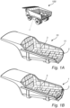
- Fig. 1A shows an exemplifying embodiment of a load carrying vehicle 100 and a load carrying container 10.
- the load carrying container 10 comprises a lining 3 covering the load carrying surfaces of the load carrying container 10.
- the lining 3 here comprises a plurality of liner elements which are arranged in rows and columns at the load carrying surfaces of the load carrying container.
- the liner elements are generally of an elastic material, such as a rubber or a polyurethane. It is however possible to use other materials for the liner elements, as well as to combine liner elements of an elastic material with liner elements of another material, e.g. a metal. In the latter case, the liner elements of elastic material and the liner elements made of metal are arranged to cover different portions of the load carrying container 10 surface.
- An embodiment of the retention system 1 of the present invention is arranged at an open rear end 11 of the load carrying container 10, also referred to from hereinafter as a truck box.
- the retention system 1 comprises a retention portion 2 which is pivotable between a first, raised, retaining position and a second, lowered position.
- the retention portion 2 is in the second, lowered position, in which the retention portion 2 is flush with the bottom of the truck box 10. It is also possible, within the concept of the present invention, to provide a retention portion 2 which is not flush with the bottom of the truck box 10 in the second position. It is for example possible that the retention portion 2 is slightly inclined also in the second position.
- Fig. 1B shows an exemplifying embodiment of a retention system 1 of a truck box 10, with the retention portion 2 in a first, raised position.
- the retention system 1 is arranged at the rear end 11 of the truck box 10.
- the retention portion 2 In the first, raised position, the retention portion 2 is arranged substantially upright, or inclined with respect to the bottom of the truck box 10. Typically, an angle ⁇ between the retention portion 2 and the bottom of the truck box is in the range of 90 to 180 degrees.
- the retention portion 2 is integrated with the lining 3 of the bottom of the truck box 10. More specifically, the retention portion 2 constitutes an end portion of the lining 3.
- the end portion of the lining 3 constituted by the retention portion 2 is not attached to the base 15 of the truck box 10 (see Figs. 2-4 ), contrary to the remaining portion of the lining 3.
- at least the end portion of the lining 3, constituted by the retention portion 2 is made of an elastic material, suitable examples of which are rubber, polyurethane or materials having similar mechanical properties. The elasticity of this type of materials allows the retention portion 2 to be bent into the first, raised position, without the use of any external hinging elements. It is, however, also conceivable within the inventive concept to provide a retention portion 2 which is not integrated with the lining 3, but arranged for example on top of the lining 3.
- the retention system 1 further comprises a drive element 4 for moving the retention portion 2 between the first and second positions, see Figs. 2-4 .
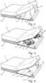
- An embodiment of a drive element 4 of the retention system 1 according to the present invention is shown in Fig. 2 .
- the drive element 4 is here arranged below the retention portion 2.
- the drive element 4 comprises an inflatable unit 41.
- the inflatable unit 41 can be inflated and deflated by means of the respective injection or extraction of a gas, such as air or any other gas suitable for the purpose. It can also be inflated or deflated by means of injection or extraction of a liquid, such as water or any other for the purpose suitable liquid.
- the inflatable unit 41 comprises a bottom surface 6 and a top surface 7, and is, in the exemplifying embodiment, arranged below the lining 3 of the truck box 10.
- the top surface 7 is connected to the lower surface of the retention portion 2, here the lining 3 of the truck box 10.
- the base 15 of the truck box 10, at the location of the drive unit 4, comprises a recess 5.
- the bottom surface 6 of the inflatable unit 41 is connected to the upper surface of the recess 5.
- the recess 5 is arranged for receiving the inflatable unit 41, partly or completely, when it is in a deflated state, corresponding to the second, lowered position of the retention portion 2.
- the recess 5 is preferably arranged to receive the deflated inflatable unit 41 completely, such that the retention portion 2 does not protrude from an upper surface of the bottom of the truck box 10 in the second, lowered position.
- the recess 5 thus enables the retention portion 2 to be flush with the bottom of the truck box 10 in the second position.
- the driving element 4 comprises two mechanically operable hoisting elements 42.
- the hoisting elements 42 are arranged below the retention portion 2 and at least partly received in the recess 5 in the base 15 of the truck box 10.
- the hoisting elements comprise a first end 8 and a second end 9.
- the first end 8 of the hoisting elements 42 is connected with the recess 5 of the base 15 of the truck box 10.
- the second end 9 of the hoisting elements 42 is connected with a lower surface of the retention portion 2.
- the hoisting elements 42 are furthermore operable between an extended position, corresponding to the first, raised position of the retention portion 2, and a compressed position, corresponding to the second, lowered, position of the retention portion 2.
- the recess 5 is preferably arranged to completely receive the hoisting elements 42.
- the retention portion 2 is flush with the upper surface of the bottom of the truck box 10 when in the second, lowered position.
- hoisting elements 42 which are partly receivable in the recess 5, such that the retention portion 2 is slightly inclined in the second position.
- the number of hoisting elements 42 is not limited to two. Therefore, a retention system 1 comprising one or three or more hoisting elements 42 is also conceivable within the concept of the present invention.
- FIG. 4 A fourth embodiment of the drive unit 4 of the retention system 1 according to the present invention is shown in Fig. 4 .
- the drive unit 4 of the retention system 1 here exemplified comprises two pneumatic or hydraulic cylinders 43.
- the cylinders 43 comprise a first end 12 and a second end 13, and are arranged below the retention portion 2.
- the first end 12 of each cylinder 43 is connected with the recess 5 of the base 15 of the truck box 10.
- the second end 13 of each cylinder 43 is connected to a lower surface of the retention portion 2.
- the cylinders 43 are thus at least partly receivable in the recess 5 of the base 15 of the truck box 10.
- the cylinders 43 are furthermore extendible. As the cylinders are extended, the retention portion 2 is raised to the first, raised position. As the cylinders are collapsed, the retention portion 2 is lowered to the second, lowered position. In this position, the cylinders 43 are completely receivable in the recess 5 of the base 15 of the truck box 10, such that the retention portion 2 is flush with the bottom of the truck box 10. It is also possible, however, that the cylinders 43 are partly received in the recess 5, such that the retention portion 2 rests slightly inclined in the second position. A person skilled in the art realizes that any number of cylinders 43, such as for example one or three or more, is also conceivable within the concept of the present invention.
- the drive unit 4 can be operable at a distance from the retention system 1.
- the drive unit 4 can be controlled from a driver's seat of the load carrying vehicle 100 onto which a truck box 10 with the retention system 1 is mounted. It is also possible to control the drive unit 4 from a location on the truck box 10, or from a position outside of the truck box 10 or of the load carrying vehicle 100.
- a locking device (not shown) is provided.
- the locking device is arranged to lock the retention portion 2 in the second, lowered position. In this position, the retention portion is substantially flush with respect to the bottom of the truck box.
- the retention portion 2 comprises an upwardly inclined upper surface and is generally of a somewhat triangular geometry, extending from the bottom of the truck box to the inclined surface.
- Such a retention portion 2 may constitute an end portion of the lining 3, which has a thickness that increases towards the end thereof.
- the retention portion comprises several rows and columns of liner elements, it is also possible to use one row only.
- the rearmost row of liner elements Preferably the rearmost row of liner elements.
- many lining solutions for truck boxes comprise liner elements made from rubber makes it possible to create a hinged pivoting point, or rather hinged pivoting line in the liner element as such. This means that only a forwardmost part of the rearmost row of liner elements may be attached, by bolting or any other suitable means, to the truck box, whereas the rearmost part of the rearmost row of liner elements are attached to the drive element. As the drive element is activated, the liner element(s) will pivot by bending along a line, creating the mentioned hinge.
- the present invention also makes it possible to alter the tipping point of the load carrying container by changing the position of the retention portion. Also, the material flow rate during unloading can be affected by changing the position of the retention portion during unloading.
- the skilled person realizes that it is convenient to protect the drive unit from rock, gravel, debris and similar which may clog parts of the drive unit and bring the drive unit out of order. This could be done by encapsulating the drive unit such that it is protected from intrusion of such material also when the retention portion is in a semi-raised position.
- the encapsulation can be achieved in different ways, e.g. by arranging a flexible membrane (plastic, textile etc.) surrounding the drive unit. Other solutions are also conceivable, for example a telescopically extendable encapsulation.
- the drive unit does not necessarily have to be arranged in a recess in the base only. It is also possible to provide a similar recess in the lining, in combination with the recess in the base or as an alternative thereto. Further, it is possible to arrange the drive unit in a box or similar which is attached to an underside of the base such that the drive unit extends through an opening in the base and is attached to a lower surface of the retention portion.
Landscapes
- Engineering & Computer Science (AREA)
- Transportation (AREA)
- Mechanical Engineering (AREA)
- Loading Or Unloading Of Vehicles (AREA)
- Handcart (AREA)
- Warehouses Or Storage Devices (AREA)
- Load-Engaging Elements For Cranes (AREA)
- Stacking Of Articles And Auxiliary Devices (AREA)
- Filling Or Discharging Of Gas Storage Vessels (AREA)
Description
- The present invention relates to a retention system for a load carrying container, and to a load carrying container and a vehicle comprising such a retention system.
- In the mining industry, load carrying vehicles are used to transport mined material out of and between different locations in the mines. These load carrying vehicles generally have a load carrying container, also referred to as a truck box, with an open top and rear end, for easy loading and unloading of the material. It is of high interest to maximize the load capacity of the truck box to enable transportation of large quantities of material and thereby render the mining process as efficient as possible.
- The design and structural materials for the truck box have thus been adapted to maximize load capacity. However, the load capacity is not only restricted by the dimensions of the truck box or its weight restrictions, but also of the travel path of the load carrying vehicle. In some locations, considerably steep hills within the mine can sometimes lead to an undesired loss of load due to material displacement towards the rearmost end of the truck box and spill therefrom.
- Some attempts to remedy this problem have been made, for example by providing a truck box with a tailgate at its rear end. When transporting heavy material though, there can be a problem for the tailgate to resist the high loads resting thereon. A fixed tailgate can also have an impact on the unloading conditions requiring a higher tilt of the truck box when unloading to ensure complete unloading of the truck box. Another example provided is to suspend the truck box such that the inclination can be compensated for and the truck box remain more level than the vehicle as it traverses a steep hill.
- This type of suspension system, however, is quite costly and complex. Another solution comprising retention means is described in
WO 03/043850 claim 1. - An object of the invention is to overcome, or at least lessen the above mentioned problems. A particular object is to provide an improved retention system for load carrying containers.
- To better address this concern, in a first aspect of the invention there is presented a retention system for a load carrying container comprising a retention portion which is arrangeable at or near a rear end of a load carrying container. The retention portion is pivotable between a first, raised position and a second, lowered position. The retention system further comprises a drive element for moving the pivotable portion between the first and second positions, respectively. The retention portion constitutes an end portion of a lining of the load carrying container. The end portion of the lining constituted by the retention portion is not attached to a base of the load carrying container, contrary to the remaining portion of the lining, and the retention portion is made of an elastic material
- The retention system allows for a higher load capacity as it is able to retain load which is displaced towards the rear of the truck box as the truck is e.g. driving uphill. When the truck box is loaded, the retention portion is set in the first position in which it is raised, such to provide a vertical or at least inclined wall which can prevent material from falling back with the force of gravity as the truck box is transported over a steep slope.
- In accordance with an embodiment of the retention system, the drive element is arranged below the retention portion. By arranging it below the retention portion, simple and reliable force transmission is safeguarded.
- In accordance with an embodiment of the retention system the drive element is operable from a distance. By being able to operate the system from e.g. the driver's cabin, use of the system is safe and saves time.
- In accordance with an embodiment of the retention system, the drive element comprises an inflatable unit. An inflatable unit is space saving and can easily be applied at many locations.
- In accordance with an embodiment of the retention system, the inflatable unit is inflated and deflated by means of a gas.
- In accordance with an embodiment of the retention system, the inflatable unit is inflated and deflated by means of a liquid.
- In accordance with an embodiment of the retention system the drive element comprises a mechanical hoisting element. Mechanical hoisting elements, comprising e.g. threaded hoisting elements, are powerful and simple in construction.
- In accordance with an embodiment of the retention system the drive element comprises a hydraulic or pneumatic cylinder. Such cylinders are able to create high forces and can often use the existing systems of the mining truck.
- In accordance with the invention, the retention portion is integrated in a lining of the load carrying container. By using the lining system of the container, substantial savings in material costs can be done in comparison with other retaining solutions.
- In accordance with an embodiment of the retention system the lining is comprised of elements at least in part made from rubber. The use of rubber in the lining is advantageous, partly due to the capacity of rubber to absorb shocks and therefore, not break or permanently deform as load hits the lining. Furthermore, the elastic properties and the flexibility of rubber enables bending of the retention portion to the first, raised position, which provides the advantage of avoiding additional hinging elements or similar. The drive element can force a part of a liner element upwardly, thereby bending it without using any external hinging element. The use of rubber will create a smooth curvature at the bending position instead of a sharp edge that would typically be the case when using a hinge. Other possible materials for the lining comprises polyurethanes, polyurethanes and ceramics or possibly combinations thereof.
- According to a second aspect of the invention, there is provided a load carrying container comprising a retention system as disclosed herein.
- In accordance with an embodiment of the load carrying container, the retention portion is at an angle α with respect to a bottom of the load carrying container in the first, raised, position.
- In accordance with an embodiment of the load carrying container, the angle α is between 90° and 180°.
- In accordance with an embodiment of the load carrying container, the retention portion does not protrude from an upper surface of a bottom of the load carrying container in the second, lowered position. This facilitates the loading and the unloading process considerably.
- In accordance with an embodiment of the load carrying container, a compartment is arranged in the load carrying container, wherein the drive element is located in said compartment. This makes it possible to keep the retention portion flush with the rest of the bottom of the container when it is in the second, lowered position. This means that the system has no drawbacks during e.g. unloading of that loaded material in comparison with a container according to prior art.
- According to a third aspect of the invention, there is provided a load carrying vehicle comprising a load carrying container as disclosed herein.
- According to a fourth aspect of the invention, there is provided a method for retaining material in a load carrying container, the method comprising providing a load carrying container. The method further comprises the step of setting the retention portion of the load carrying container in a first, raised position for loading and transportation of the load of said load carrying container.
- Other objectives, features and advantages of the present invention will appear from the following detailed disclosure.
- Generally, all terms used herein are to be interpreted according to their ordinary meaning in the technical field, unless explicitly defined otherwise herein. All references to "a/an/the [element, device, component, means, step, etc.]" are to be interpreted openly as referring to at least one instance of said element, device, component, means, step, etc., unless explicitly stated otherwise.
- As used herein, the term "comprising" and variations of that term are not intended to exclude other additives, components, integers or steps.
- The invention will be described in more detail and with reference to the appended drawings in which:
-
Fig. 1A is a schematic view of a load carrying vehicle and container with an embodiment of a retention system according to the invention; -
Fig. 1B is a schematic view of an embodiment of a retention system according to the invention; -
Fig. 2 is a schematic view of a second embodiment of a retention system according to the invention; -
Fig. 3 is a schematic view of a third embodiment of a retention system according to the invention; and -
Fig. 4 is a schematic view of a fourth embodiment of a retention system according to the invention. - The present invention will now be described more fully hereinafter with reference to the accompanying drawings, in which exemplifying embodiments of the invention are shown. The present invention may, however, be embodied in many different forms and should not be construed as limited to the embodiments set forth herein; rather, these embodiments are provided for thoroughness and completeness, and to fully convey the scope of the invention to the skilled addressee. Like reference characters refer to like elements throughout.
-
Fig. 1A shows an exemplifying embodiment of aload carrying vehicle 100 and aload carrying container 10. Theload carrying container 10 comprises alining 3 covering the load carrying surfaces of theload carrying container 10. Thelining 3 here comprises a plurality of liner elements which are arranged in rows and columns at the load carrying surfaces of the load carrying container. The liner elements are generally of an elastic material, such as a rubber or a polyurethane. It is however possible to use other materials for the liner elements, as well as to combine liner elements of an elastic material with liner elements of another material, e.g. a metal. In the latter case, the liner elements of elastic material and the liner elements made of metal are arranged to cover different portions of theload carrying container 10 surface. An embodiment of theretention system 1 of the present invention is arranged at an openrear end 11 of theload carrying container 10, also referred to from hereinafter as a truck box. Theretention system 1 comprises aretention portion 2 which is pivotable between a first, raised, retaining position and a second, lowered position. In the exemplifying embodiment shown inFig. 1A , theretention portion 2 is in the second, lowered position, in which theretention portion 2 is flush with the bottom of thetruck box 10. It is also possible, within the concept of the present invention, to provide aretention portion 2 which is not flush with the bottom of thetruck box 10 in the second position. It is for example possible that theretention portion 2 is slightly inclined also in the second position. -
Fig. 1B shows an exemplifying embodiment of aretention system 1 of atruck box 10, with theretention portion 2 in a first, raised position. In the example here shown, theretention system 1 is arranged at therear end 11 of thetruck box 10. - In the first, raised position, the
retention portion 2 is arranged substantially upright, or inclined with respect to the bottom of thetruck box 10. Typically, an angle α between theretention portion 2 and the bottom of the truck box is in the range of 90 to 180 degrees. - In the exemplifying embodiment of
Fig. 1A and 1B , theretention portion 2 is integrated with thelining 3 of the bottom of thetruck box 10. More specifically, theretention portion 2 constitutes an end portion of thelining 3. In this embodiment, the end portion of thelining 3 constituted by theretention portion 2 is not attached to thebase 15 of the truck box 10 (seeFigs. 2-4 ), contrary to the remaining portion of thelining 3. Here, at least the end portion of thelining 3, constituted by theretention portion 2, is made of an elastic material, suitable examples of which are rubber, polyurethane or materials having similar mechanical properties. The elasticity of this type of materials allows theretention portion 2 to be bent into the first, raised position, without the use of any external hinging elements. It is, however, also conceivable within the inventive concept to provide aretention portion 2 which is not integrated with thelining 3, but arranged for example on top of thelining 3. - The
retention system 1 further comprises adrive element 4 for moving theretention portion 2 between the first and second positions, seeFigs. 2-4 . An embodiment of adrive element 4 of theretention system 1 according to the present invention is shown inFig. 2 . Thedrive element 4 is here arranged below theretention portion 2. In this exemplifying embodiment, thedrive element 4 comprises aninflatable unit 41. Theinflatable unit 41 can be inflated and deflated by means of the respective injection or extraction of a gas, such as air or any other gas suitable for the purpose. It can also be inflated or deflated by means of injection or extraction of a liquid, such as water or any other for the purpose suitable liquid. - The
inflatable unit 41 comprises abottom surface 6 and atop surface 7, and is, in the exemplifying embodiment, arranged below thelining 3 of thetruck box 10. Thetop surface 7 is connected to the lower surface of theretention portion 2, here the lining 3 of thetruck box 10. Thebase 15 of thetruck box 10, at the location of thedrive unit 4, comprises arecess 5. Thebottom surface 6 of theinflatable unit 41 is connected to the upper surface of therecess 5. Therecess 5 is arranged for receiving theinflatable unit 41, partly or completely, when it is in a deflated state, corresponding to the second, lowered position of theretention portion 2. Therecess 5 is preferably arranged to receive the deflatedinflatable unit 41 completely, such that theretention portion 2 does not protrude from an upper surface of the bottom of thetruck box 10 in the second, lowered position. Therecess 5 thus enables theretention portion 2 to be flush with the bottom of thetruck box 10 in the second position. - Another embodiment of the
drive unit 4 of theretention system 1 according to the present invention is shown inFig. 3 . Here, the drivingelement 4 comprises two mechanicallyoperable hoisting elements 42. The hoistingelements 42 are arranged below theretention portion 2 and at least partly received in therecess 5 in thebase 15 of thetruck box 10. Furthermore, the hoisting elements comprise afirst end 8 and asecond end 9. Thefirst end 8 of the hoistingelements 42 is connected with therecess 5 of thebase 15 of thetruck box 10. Thesecond end 9 of the hoistingelements 42 is connected with a lower surface of theretention portion 2. - The hoisting
elements 42 are furthermore operable between an extended position, corresponding to the first, raised position of theretention portion 2, and a compressed position, corresponding to the second, lowered, position of theretention portion 2. Therecess 5 is preferably arranged to completely receive thehoisting elements 42. In this case, theretention portion 2 is flush with the upper surface of the bottom of thetruck box 10 when in the second, lowered position. However, it is also possible to provide hoistingelements 42 which are partly receivable in therecess 5, such that theretention portion 2 is slightly inclined in the second position. It should furthermore be pointed out that the number of hoistingelements 42 is not limited to two. Therefore, aretention system 1 comprising one or three ormore hoisting elements 42 is also conceivable within the concept of the present invention. - A fourth embodiment of the
drive unit 4 of theretention system 1 according to the present invention is shown inFig. 4 . Thedrive unit 4 of theretention system 1 here exemplified comprises two pneumatic orhydraulic cylinders 43. Thecylinders 43 comprise afirst end 12 and asecond end 13, and are arranged below theretention portion 2. Thefirst end 12 of eachcylinder 43 is connected with therecess 5 of thebase 15 of thetruck box 10. Thesecond end 13 of eachcylinder 43 is connected to a lower surface of theretention portion 2. Thecylinders 43 are thus at least partly receivable in therecess 5 of thebase 15 of thetruck box 10. - The
cylinders 43 are furthermore extendible. As the cylinders are extended, theretention portion 2 is raised to the first, raised position. As the cylinders are collapsed, theretention portion 2 is lowered to the second, lowered position. In this position, thecylinders 43 are completely receivable in therecess 5 of thebase 15 of thetruck box 10, such that theretention portion 2 is flush with the bottom of thetruck box 10. It is also possible, however, that thecylinders 43 are partly received in therecess 5, such that theretention portion 2 rests slightly inclined in the second position. A person skilled in the art realizes that any number ofcylinders 43, such as for example one or three or more, is also conceivable within the concept of the present invention. - The
drive unit 4 can be operable at a distance from theretention system 1. For example, thedrive unit 4 can be controlled from a driver's seat of theload carrying vehicle 100 onto which atruck box 10 with theretention system 1 is mounted. It is also possible to control thedrive unit 4 from a location on thetruck box 10, or from a position outside of thetruck box 10 or of theload carrying vehicle 100. - In an embodiment of the
retention system 1, a locking device (not shown) is provided. The locking device is arranged to lock theretention portion 2 in the second, lowered position. In this position, the retention portion is substantially flush with respect to the bottom of the truck box. - The skilled person realizes that a number of modifications of the embodiments described herein are possible without departing from the scope of the invention, which is defined in the appended claims. For example, it is also possible to provide a
retention system 1 which permanently maintains the retaining position. In this case, theretention portion 2 comprises an upwardly inclined upper surface and is generally of a somewhat triangular geometry, extending from the bottom of the truck box to the inclined surface. Such aretention portion 2 may constitute an end portion of thelining 3, which has a thickness that increases towards the end thereof. - The skilled person also realizes that even though the embodiments show that the retention portion comprises several rows and columns of liner elements, it is also possible to use one row only. Preferably the rearmost row of liner elements. The fact that many lining solutions for truck boxes comprise liner elements made from rubber makes it possible to create a hinged pivoting point, or rather hinged pivoting line in the liner element as such. This means that only a forwardmost part of the rearmost row of liner elements may be attached, by bolting or any other suitable means, to the truck box, whereas the rearmost part of the rearmost row of liner elements are attached to the drive element. As the drive element is activated, the liner element(s) will pivot by bending along a line, creating the mentioned hinge. The skilled person further realizes that the present invention also makes it possible to alter the tipping point of the load carrying container by changing the position of the retention portion. Also, the material flow rate during unloading can be affected by changing the position of the retention portion during unloading.
- Further, the skilled person realizes that it is convenient to protect the drive unit from rock, gravel, debris and similar which may clog parts of the drive unit and bring the drive unit out of order. This could be done by encapsulating the drive unit such that it is protected from intrusion of such material also when the retention portion is in a semi-raised position. The encapsulation can be achieved in different ways, e.g. by arranging a flexible membrane (plastic, textile etc.) surrounding the drive unit. Other solutions are also conceivable, for example a telescopically extendable encapsulation.
- The skilled person also realizes that the drive unit does not necessarily have to be arranged in a recess in the base only. It is also possible to provide a similar recess in the lining, in combination with the recess in the base or as an alternative thereto. Further, it is possible to arrange the drive unit in a box or similar which is attached to an underside of the base such that the drive unit extends through an opening in the base and is attached to a lower surface of the retention portion.
Claims (14)
- Retention system (1) for a load carrying container (10), comprisinga retention portion (2) arrangeable at or near a rear end of a load carrying container (10), which retention portion (2) is pivotable between a first, raised position and a second, lowered position; anda drive element (4) for moving the pivotable retention portion (2) between the first and second positions, characterized in that the retention portion (2) constitutes an end portion of a lining (3) of the load carrying container (10), wherein the end portion of the lining (3) constituted by the retention portion (2) is not attached to a base (15) of the load carrying container (10), contrary to the remaining portion of the lining (3), and wherein the retention portion is made of an elastic material.
- Retention system (1) according to claim 1, wherein the drive element (4) is arranged below the retention portion (2).
- Retention system (1) according to claim 1 or 2, wherein the drive element (4) is operable from a distance.
- Retention system (1) according to any one of the preceding claims, wherein the drive element (4) comprises an inflatable unit (41).
- Retention system (1) according to claim 4, wherein the inflatable unit (41) can be inflated and deflated by means of a gas.
- Retention system (1) according to claim 4, wherein the inflatable unit (41) is inflated and deflated by means of a liquid.
- Retention system (41) according to any one of claims 1-3, wherein the drive element (4) comprises a mechanical hoisting element (42).
- Retention system (1) according to any one of claims 1-3, wherein the drive element (4) comprises a hydraulic or pneumatic cylinder (43).
- Retention system (1) according to claim 1, wherein the lining (3) comprises elements at least in part made from rubber.
- A load carrying container (10) comprising a retention system (1) according to any one of the preceding claims.
- A load carrying container (10) according to claim 10, wherein the retention portion (2) does not protrude from an upper surface of a bottom of the load carrying container (10) in the second, lowered position.
- A load carrying container (10) according to claim 10, comprising a compartment, wherein the drive element is located in said compartment.
- A load carrying vehicle (100) comprising a load carrying container (10) according to claim 12.
- A method for retaining material in a load carrying container, the method comprising providing a load carrying container (10) according to any of claims 10-12, setting the retention portion (2) of said load carrying container (10) in a first, raised position for loading and transportation of the load of said load carrying container (10).
Applications Claiming Priority (2)
| Application Number | Priority Date | Filing Date | Title |
|---|---|---|---|
| EP18157179.5A EP3527425B1 (en) | 2018-02-16 | 2018-02-16 | Load retention system |
| PCT/EP2019/053757 WO2019158673A1 (en) | 2018-02-16 | 2019-02-15 | Load retention system |
Publications (2)
| Publication Number | Publication Date |
|---|---|
| EP3752390A1 EP3752390A1 (en) | 2020-12-23 |
| EP3752390B1 true EP3752390B1 (en) | 2023-11-22 |
Family
ID=61231141
Family Applications (2)
| Application Number | Title | Priority Date | Filing Date |
|---|---|---|---|
| EP18157179.5A Active EP3527425B1 (en) | 2018-02-16 | 2018-02-16 | Load retention system |
| EP19704021.5A Active EP3752390B1 (en) | 2018-02-16 | 2019-02-15 | Load retention system |
Family Applications Before (1)
| Application Number | Title | Priority Date | Filing Date |
|---|---|---|---|
| EP18157179.5A Active EP3527425B1 (en) | 2018-02-16 | 2018-02-16 | Load retention system |
Country Status (14)
| Country | Link |
|---|---|
| US (1) | US11351904B2 (en) |
| EP (2) | EP3527425B1 (en) |
| CN (1) | CN111801246B (en) |
| AU (1) | AU2019220411B2 (en) |
| CA (1) | CA3087929A1 (en) |
| CL (1) | CL2020002098A1 (en) |
| ES (1) | ES2894934T3 (en) |
| FI (1) | FI3752390T3 (en) |
| MX (1) | MX2020008555A (en) |
| PE (1) | PE20200968A1 (en) |
| RS (1) | RS62409B1 (en) |
| UA (1) | UA126984C2 (en) |
| WO (1) | WO2019158673A1 (en) |
| ZA (1) | ZA202005055B (en) |
Families Citing this family (5)
| Publication number | Priority date | Publication date | Assignee | Title |
|---|---|---|---|---|
| EP3418116A1 (en) | 2017-06-22 | 2018-12-26 | Metso Sweden Ab | A lining for a haul truck body, a transition lining element and a method for fastening a lining |
| CN116669990A (en) * | 2020-11-16 | 2023-08-29 | 山特维克矿山工程机械有限公司 | Tip box arrangements for vehicles, tip boxes and mining vehicles |
| CL2020003404A1 (en) * | 2020-12-28 | 2021-06-18 | Desarrollos Tecnologicos S A | Hopper containing deformable extension |
| EP4029732A1 (en) * | 2021-01-18 | 2022-07-20 | Metso Outotec Finland Oy | Wear liner element for a truck haul body |
| US11932312B2 (en) | 2021-12-10 | 2024-03-19 | Caterpillar Inc. | Tail extension for a truck bed |
Family Cites Families (9)
| Publication number | Priority date | Publication date | Assignee | Title |
|---|---|---|---|---|
| US3773385A (en) * | 1972-07-10 | 1973-11-20 | S Sandberg | Device for facilitating of the operation of automatically operable platform walls or gates at dump vehicles |
| US3953950A (en) * | 1974-10-31 | 1976-05-04 | The Johnson Rubber Company | Truck bed liner and dock bumper combination |
| US4077328A (en) * | 1976-06-11 | 1978-03-07 | Glenn Taylor | Rotary dump |
| US5560684A (en) | 1992-09-16 | 1996-10-01 | Xpt Power Industries Pty. Ltd. | Inflatable bag and tipping apparatus including same |
| US5823630A (en) * | 1997-03-14 | 1998-10-20 | Omni Holding Company | Pivot lip dump gate |
| AUPR902901A0 (en) * | 2001-11-23 | 2001-12-20 | Keech Castings Australia Pty Limited | A pivotal tail extension |
| US8708391B2 (en) * | 2010-01-25 | 2014-04-29 | Corrosion Engineering, Inc. | Liner systems |
| ES2784757T3 (en) * | 2011-12-23 | 2020-09-30 | Metso Sweden Ab | Wear-resistant lining element for edge protection and method of making the same |
| CN103395385A (en) | 2013-08-12 | 2013-11-20 | 三一矿机有限公司 | Mining dump truck bed with lining plates and mining dump truck |
-
2018
- 2018-02-16 ES ES18157179T patent/ES2894934T3/en active Active
- 2018-02-16 RS RS20211229A patent/RS62409B1/en unknown
- 2018-02-16 EP EP18157179.5A patent/EP3527425B1/en active Active
-
2019
- 2019-02-15 AU AU2019220411A patent/AU2019220411B2/en active Active
- 2019-02-15 UA UAA202005355A patent/UA126984C2/en unknown
- 2019-02-15 EP EP19704021.5A patent/EP3752390B1/en active Active
- 2019-02-15 PE PE2020001200A patent/PE20200968A1/en unknown
- 2019-02-15 MX MX2020008555A patent/MX2020008555A/en unknown
- 2019-02-15 CA CA3087929A patent/CA3087929A1/en active Pending
- 2019-02-15 FI FIEP19704021.5T patent/FI3752390T3/en active
- 2019-02-15 US US16/969,660 patent/US11351904B2/en active Active
- 2019-02-15 WO PCT/EP2019/053757 patent/WO2019158673A1/en not_active Ceased
- 2019-02-15 CN CN201980012563.3A patent/CN111801246B/en active Active
-
2020
- 2020-08-13 CL CL2020002098A patent/CL2020002098A1/en unknown
- 2020-08-14 ZA ZA2020/05055A patent/ZA202005055B/en unknown
Also Published As
| Publication number | Publication date |
|---|---|
| ZA202005055B (en) | 2022-01-26 |
| FI3752390T3 (en) | 2024-02-15 |
| CA3087929A1 (en) | 2019-08-22 |
| BR112020015530A2 (en) | 2021-02-02 |
| EP3527425B1 (en) | 2021-07-07 |
| RU2020128621A (en) | 2022-03-16 |
| CN111801246A (en) | 2020-10-20 |
| US20200398727A1 (en) | 2020-12-24 |
| PE20200968A1 (en) | 2020-09-28 |
| CL2020002098A1 (en) | 2020-12-18 |
| UA126984C2 (en) | 2023-03-01 |
| ES2894934T3 (en) | 2022-02-16 |
| EP3752390A1 (en) | 2020-12-23 |
| MX2020008555A (en) | 2021-01-08 |
| EP3527425A1 (en) | 2019-08-21 |
| WO2019158673A1 (en) | 2019-08-22 |
| AU2019220411B2 (en) | 2024-08-15 |
| RS62409B1 (en) | 2021-10-29 |
| US11351904B2 (en) | 2022-06-07 |
| AU2019220411A1 (en) | 2020-09-10 |
| CN111801246B (en) | 2022-09-16 |
Similar Documents
| Publication | Publication Date | Title |
|---|---|---|
| EP3752390B1 (en) | Load retention system | |
| CN101372240B (en) | Cargo access and retention system for a passenger vehicle | |
| JP2015116920A (en) | Dump device loadable on truck | |
| AU2007293721B2 (en) | Mechanical tailgate | |
| KR200486557Y1 (en) | Door apparatus for dump truck | |
| KR102044089B1 (en) | Dump body module for general truck mounting | |
| CN110914106A (en) | Deformable vehicle for the transport of goods | |
| US4084852A (en) | Roll-over protection structure for dump truck | |
| KR200441680Y1 (en) | Vehicle Loaded Container Load Unloading Device | |
| BR112020015530B1 (en) | RESTRAINT SYSTEM, CARGO TRANSPORT CONTAINER, CARGO TRANSPORT VEHICLE AND METHOD FOR RESTRAINING MATERIAL IN A CARGO TRANSPORT CONTAINER | |
| US8417425B2 (en) | Mechanism for stabilizing granular material on a vehicle bed | |
| CN2878131Y (en) | Side turning self-discharging car capable of traveling | |
| CN100462254C (en) | Walkable rollover dump truck | |
| CN219295248U (en) | Mining dump truck body assembly | |
| JP2000507899A (en) | Improved bulk material handling vehicles | |
| RU2725847C1 (en) | Automatic evacuator | |
| CN221214273U (en) | Side plate assembly of dump truck, container and mining truck dump truck | |
| CN215097203U (en) | Dumper back door and control system | |
| KR100836320B1 (en) | Tail gate hoisting device of truck | |
| JP2997453B1 (en) | Dump truck | |
| KR100502743B1 (en) | Cargo working system for vehicle | |
| CN101428577A (en) | Self-discharging body in back-front sequence | |
| JP2009196771A (en) | Bulk cargo unloading device for self-unloading ship | |
| KR20040090123A (en) | Trailer for transporting grain |
Legal Events
| Date | Code | Title | Description |
|---|---|---|---|
| STAA | Information on the status of an ep patent application or granted ep patent |
Free format text: STATUS: UNKNOWN |
|
| STAA | Information on the status of an ep patent application or granted ep patent |
Free format text: STATUS: THE INTERNATIONAL PUBLICATION HAS BEEN MADE |
|
| PUAI | Public reference made under article 153(3) epc to a published international application that has entered the european phase |
Free format text: ORIGINAL CODE: 0009012 |
|
| STAA | Information on the status of an ep patent application or granted ep patent |
Free format text: STATUS: REQUEST FOR EXAMINATION WAS MADE |
|
| 17P | Request for examination filed |
Effective date: 20200910 |
|
| AK | Designated contracting states |
Kind code of ref document: A1 Designated state(s): AL AT BE BG CH CY CZ DE DK EE ES FI FR GB GR HR HU IE IS IT LI LT LU LV MC MK MT NL NO PL PT RO RS SE SI SK SM TR |
|
| AX | Request for extension of the european patent |
Extension state: BA ME |
|
| DAV | Request for validation of the european patent (deleted) | ||
| DAX | Request for extension of the european patent (deleted) | ||
| STAA | Information on the status of an ep patent application or granted ep patent |
Free format text: STATUS: EXAMINATION IS IN PROGRESS |
|
| 17Q | First examination report despatched |
Effective date: 20210812 |
|
| GRAP | Despatch of communication of intention to grant a patent |
Free format text: ORIGINAL CODE: EPIDOSNIGR1 |
|
| STAA | Information on the status of an ep patent application or granted ep patent |
Free format text: STATUS: GRANT OF PATENT IS INTENDED |
|
| INTG | Intention to grant announced |
Effective date: 20230524 |
|
| P01 | Opt-out of the competence of the unified patent court (upc) registered |
Effective date: 20230527 |
|
| GRAS | Grant fee paid |
Free format text: ORIGINAL CODE: EPIDOSNIGR3 |
|
| RAP1 | Party data changed (applicant data changed or rights of an application transferred) |
Owner name: METSO OUTOTEC FINLAND OY |
|
| GRAA | (expected) grant |
Free format text: ORIGINAL CODE: 0009210 |
|
| STAA | Information on the status of an ep patent application or granted ep patent |
Free format text: STATUS: THE PATENT HAS BEEN GRANTED |
|
| AK | Designated contracting states |
Kind code of ref document: B1 Designated state(s): AL AT BE BG CH CY CZ DE DK EE ES FI FR GB GR HR HU IE IS IT LI LT LU LV MC MK MT NL NO PL PT RO RS SE SI SK SM TR |
|
| REG | Reference to a national code |
Ref country code: GB Ref legal event code: FG4D |
|
| REG | Reference to a national code |
Ref country code: CH Ref legal event code: EP |
|
| REG | Reference to a national code |
Ref country code: DE Ref legal event code: R096 Ref document number: 602019041825 Country of ref document: DE |
|
| REG | Reference to a national code |
Ref country code: IE Ref legal event code: FG4D |
|
| RAP4 | Party data changed (patent owner data changed or rights of a patent transferred) |
Owner name: METSO FINLAND OY |
|
| REG | Reference to a national code |
Ref country code: SE Ref legal event code: TRGR |
|
| REG | Reference to a national code |
Ref country code: FI Ref legal event code: FGE |
|
| REG | Reference to a national code |
Ref country code: LT Ref legal event code: MG9D |
|
| REG | Reference to a national code |
Ref country code: NL Ref legal event code: MP Effective date: 20231122 |
|
| PG25 | Lapsed in a contracting state [announced via postgrant information from national office to epo] |
Ref country code: GR Free format text: LAPSE BECAUSE OF FAILURE TO SUBMIT A TRANSLATION OF THE DESCRIPTION OR TO PAY THE FEE WITHIN THE PRESCRIBED TIME-LIMIT Effective date: 20240223 |
|
| PG25 | Lapsed in a contracting state [announced via postgrant information from national office to epo] |
Ref country code: IS Free format text: LAPSE BECAUSE OF FAILURE TO SUBMIT A TRANSLATION OF THE DESCRIPTION OR TO PAY THE FEE WITHIN THE PRESCRIBED TIME-LIMIT Effective date: 20240322 |
|
| PG25 | Lapsed in a contracting state [announced via postgrant information from national office to epo] |
Ref country code: LT Free format text: LAPSE BECAUSE OF FAILURE TO SUBMIT A TRANSLATION OF THE DESCRIPTION OR TO PAY THE FEE WITHIN THE PRESCRIBED TIME-LIMIT Effective date: 20231122 |
|
| REG | Reference to a national code |
Ref country code: AT Ref legal event code: MK05 Ref document number: 1633541 Country of ref document: AT Kind code of ref document: T Effective date: 20231122 |
|
| PG25 | Lapsed in a contracting state [announced via postgrant information from national office to epo] |
Ref country code: NL Free format text: LAPSE BECAUSE OF FAILURE TO SUBMIT A TRANSLATION OF THE DESCRIPTION OR TO PAY THE FEE WITHIN THE PRESCRIBED TIME-LIMIT Effective date: 20231122 |
|
| PG25 | Lapsed in a contracting state [announced via postgrant information from national office to epo] |
Ref country code: AT Free format text: LAPSE BECAUSE OF FAILURE TO SUBMIT A TRANSLATION OF THE DESCRIPTION OR TO PAY THE FEE WITHIN THE PRESCRIBED TIME-LIMIT Effective date: 20231122 |
|
| PG25 | Lapsed in a contracting state [announced via postgrant information from national office to epo] |
Ref country code: ES Free format text: LAPSE BECAUSE OF FAILURE TO SUBMIT A TRANSLATION OF THE DESCRIPTION OR TO PAY THE FEE WITHIN THE PRESCRIBED TIME-LIMIT Effective date: 20231122 |
|
| PG25 | Lapsed in a contracting state [announced via postgrant information from national office to epo] |
Ref country code: NL Free format text: LAPSE BECAUSE OF FAILURE TO SUBMIT A TRANSLATION OF THE DESCRIPTION OR TO PAY THE FEE WITHIN THE PRESCRIBED TIME-LIMIT Effective date: 20231122 Ref country code: LT Free format text: LAPSE BECAUSE OF FAILURE TO SUBMIT A TRANSLATION OF THE DESCRIPTION OR TO PAY THE FEE WITHIN THE PRESCRIBED TIME-LIMIT Effective date: 20231122 Ref country code: IS Free format text: LAPSE BECAUSE OF FAILURE TO SUBMIT A TRANSLATION OF THE DESCRIPTION OR TO PAY THE FEE WITHIN THE PRESCRIBED TIME-LIMIT Effective date: 20240322 Ref country code: GR Free format text: LAPSE BECAUSE OF FAILURE TO SUBMIT A TRANSLATION OF THE DESCRIPTION OR TO PAY THE FEE WITHIN THE PRESCRIBED TIME-LIMIT Effective date: 20240223 Ref country code: ES Free format text: LAPSE BECAUSE OF FAILURE TO SUBMIT A TRANSLATION OF THE DESCRIPTION OR TO PAY THE FEE WITHIN THE PRESCRIBED TIME-LIMIT Effective date: 20231122 Ref country code: BG Free format text: LAPSE BECAUSE OF FAILURE TO SUBMIT A TRANSLATION OF THE DESCRIPTION OR TO PAY THE FEE WITHIN THE PRESCRIBED TIME-LIMIT Effective date: 20240222 Ref country code: AT Free format text: LAPSE BECAUSE OF FAILURE TO SUBMIT A TRANSLATION OF THE DESCRIPTION OR TO PAY THE FEE WITHIN THE PRESCRIBED TIME-LIMIT Effective date: 20231122 Ref country code: PT Free format text: LAPSE BECAUSE OF FAILURE TO SUBMIT A TRANSLATION OF THE DESCRIPTION OR TO PAY THE FEE WITHIN THE PRESCRIBED TIME-LIMIT Effective date: 20240322 |
|
| PG25 | Lapsed in a contracting state [announced via postgrant information from national office to epo] |
Ref country code: RS Free format text: LAPSE BECAUSE OF FAILURE TO SUBMIT A TRANSLATION OF THE DESCRIPTION OR TO PAY THE FEE WITHIN THE PRESCRIBED TIME-LIMIT Effective date: 20231122 Ref country code: PL Free format text: LAPSE BECAUSE OF FAILURE TO SUBMIT A TRANSLATION OF THE DESCRIPTION OR TO PAY THE FEE WITHIN THE PRESCRIBED TIME-LIMIT Effective date: 20231122 Ref country code: NO Free format text: LAPSE BECAUSE OF FAILURE TO SUBMIT A TRANSLATION OF THE DESCRIPTION OR TO PAY THE FEE WITHIN THE PRESCRIBED TIME-LIMIT Effective date: 20240222 Ref country code: LV Free format text: LAPSE BECAUSE OF FAILURE TO SUBMIT A TRANSLATION OF THE DESCRIPTION OR TO PAY THE FEE WITHIN THE PRESCRIBED TIME-LIMIT Effective date: 20231122 Ref country code: HR Free format text: LAPSE BECAUSE OF FAILURE TO SUBMIT A TRANSLATION OF THE DESCRIPTION OR TO PAY THE FEE WITHIN THE PRESCRIBED TIME-LIMIT Effective date: 20231122 |
|
| PG25 | Lapsed in a contracting state [announced via postgrant information from national office to epo] |
Ref country code: DK Free format text: LAPSE BECAUSE OF FAILURE TO SUBMIT A TRANSLATION OF THE DESCRIPTION OR TO PAY THE FEE WITHIN THE PRESCRIBED TIME-LIMIT Effective date: 20231122 |
|
| PG25 | Lapsed in a contracting state [announced via postgrant information from national office to epo] |
Ref country code: CZ Free format text: LAPSE BECAUSE OF FAILURE TO SUBMIT A TRANSLATION OF THE DESCRIPTION OR TO PAY THE FEE WITHIN THE PRESCRIBED TIME-LIMIT Effective date: 20231122 |
|
| PG25 | Lapsed in a contracting state [announced via postgrant information from national office to epo] |
Ref country code: SK Free format text: LAPSE BECAUSE OF FAILURE TO SUBMIT A TRANSLATION OF THE DESCRIPTION OR TO PAY THE FEE WITHIN THE PRESCRIBED TIME-LIMIT Effective date: 20231122 |
|
| PG25 | Lapsed in a contracting state [announced via postgrant information from national office to epo] |
Ref country code: SM Free format text: LAPSE BECAUSE OF FAILURE TO SUBMIT A TRANSLATION OF THE DESCRIPTION OR TO PAY THE FEE WITHIN THE PRESCRIBED TIME-LIMIT Effective date: 20231122 Ref country code: SK Free format text: LAPSE BECAUSE OF FAILURE TO SUBMIT A TRANSLATION OF THE DESCRIPTION OR TO PAY THE FEE WITHIN THE PRESCRIBED TIME-LIMIT Effective date: 20231122 Ref country code: RO Free format text: LAPSE BECAUSE OF FAILURE TO SUBMIT A TRANSLATION OF THE DESCRIPTION OR TO PAY THE FEE WITHIN THE PRESCRIBED TIME-LIMIT Effective date: 20231122 Ref country code: IT Free format text: LAPSE BECAUSE OF FAILURE TO SUBMIT A TRANSLATION OF THE DESCRIPTION OR TO PAY THE FEE WITHIN THE PRESCRIBED TIME-LIMIT Effective date: 20231122 Ref country code: EE Free format text: LAPSE BECAUSE OF FAILURE TO SUBMIT A TRANSLATION OF THE DESCRIPTION OR TO PAY THE FEE WITHIN THE PRESCRIBED TIME-LIMIT Effective date: 20231122 Ref country code: DK Free format text: LAPSE BECAUSE OF FAILURE TO SUBMIT A TRANSLATION OF THE DESCRIPTION OR TO PAY THE FEE WITHIN THE PRESCRIBED TIME-LIMIT Effective date: 20231122 Ref country code: CZ Free format text: LAPSE BECAUSE OF FAILURE TO SUBMIT A TRANSLATION OF THE DESCRIPTION OR TO PAY THE FEE WITHIN THE PRESCRIBED TIME-LIMIT Effective date: 20231122 |
|
| REG | Reference to a national code |
Ref country code: DE Ref legal event code: R097 Ref document number: 602019041825 Country of ref document: DE |
|
| REG | Reference to a national code |
Ref country code: DE Ref legal event code: R119 Ref document number: 602019041825 Country of ref document: DE |
|
| PLBE | No opposition filed within time limit |
Free format text: ORIGINAL CODE: 0009261 |
|
| STAA | Information on the status of an ep patent application or granted ep patent |
Free format text: STATUS: NO OPPOSITION FILED WITHIN TIME LIMIT |
|
| PG25 | Lapsed in a contracting state [announced via postgrant information from national office to epo] |
Ref country code: MC Free format text: LAPSE BECAUSE OF FAILURE TO SUBMIT A TRANSLATION OF THE DESCRIPTION OR TO PAY THE FEE WITHIN THE PRESCRIBED TIME-LIMIT Effective date: 20231122 |
|
| REG | Reference to a national code |
Ref country code: CH Ref legal event code: PL |
|
| PG25 | Lapsed in a contracting state [announced via postgrant information from national office to epo] |
Ref country code: LU Free format text: LAPSE BECAUSE OF NON-PAYMENT OF DUE FEES Effective date: 20240215 |
|
| PG25 | Lapsed in a contracting state [announced via postgrant information from national office to epo] |
Ref country code: CH Free format text: LAPSE BECAUSE OF NON-PAYMENT OF DUE FEES Effective date: 20240229 |
|
| GBPC | Gb: european patent ceased through non-payment of renewal fee |
Effective date: 20240222 |
|
| PG25 | Lapsed in a contracting state [announced via postgrant information from national office to epo] |
Ref country code: SI Free format text: LAPSE BECAUSE OF FAILURE TO SUBMIT A TRANSLATION OF THE DESCRIPTION OR TO PAY THE FEE WITHIN THE PRESCRIBED TIME-LIMIT Effective date: 20231122 |
|
| 26N | No opposition filed |
Effective date: 20240823 |
|
| PG25 | Lapsed in a contracting state [announced via postgrant information from national office to epo] |
Ref country code: SI Free format text: LAPSE BECAUSE OF FAILURE TO SUBMIT A TRANSLATION OF THE DESCRIPTION OR TO PAY THE FEE WITHIN THE PRESCRIBED TIME-LIMIT Effective date: 20231122 Ref country code: LU Free format text: LAPSE BECAUSE OF NON-PAYMENT OF DUE FEES Effective date: 20240215 Ref country code: CH Free format text: LAPSE BECAUSE OF NON-PAYMENT OF DUE FEES Effective date: 20240229 |
|
| REG | Reference to a national code |
Ref country code: BE Ref legal event code: MM Effective date: 20240229 |
|
| PG25 | Lapsed in a contracting state [announced via postgrant information from national office to epo] |
Ref country code: DE Free format text: LAPSE BECAUSE OF NON-PAYMENT OF DUE FEES Effective date: 20240903 |
|
| PG25 | Lapsed in a contracting state [announced via postgrant information from national office to epo] |
Ref country code: BE Free format text: LAPSE BECAUSE OF NON-PAYMENT OF DUE FEES Effective date: 20240229 |
|
| PG25 | Lapsed in a contracting state [announced via postgrant information from national office to epo] |
Ref country code: GB Free format text: LAPSE BECAUSE OF NON-PAYMENT OF DUE FEES Effective date: 20240222 |
|
| PG25 | Lapsed in a contracting state [announced via postgrant information from national office to epo] |
Ref country code: FR Free format text: LAPSE BECAUSE OF NON-PAYMENT OF DUE FEES Effective date: 20240229 |
|
| PG25 | Lapsed in a contracting state [announced via postgrant information from national office to epo] |
Ref country code: IE Free format text: LAPSE BECAUSE OF NON-PAYMENT OF DUE FEES Effective date: 20240215 |
|
| PG25 | Lapsed in a contracting state [announced via postgrant information from national office to epo] |
Ref country code: IE Free format text: LAPSE BECAUSE OF NON-PAYMENT OF DUE FEES Effective date: 20240215 Ref country code: GB Free format text: LAPSE BECAUSE OF NON-PAYMENT OF DUE FEES Effective date: 20240222 Ref country code: FR Free format text: LAPSE BECAUSE OF NON-PAYMENT OF DUE FEES Effective date: 20240229 Ref country code: DE Free format text: LAPSE BECAUSE OF NON-PAYMENT OF DUE FEES Effective date: 20240903 Ref country code: BE Free format text: LAPSE BECAUSE OF NON-PAYMENT OF DUE FEES Effective date: 20240229 |
|
| PG25 | Lapsed in a contracting state [announced via postgrant information from national office to epo] |
Ref country code: CY Free format text: LAPSE BECAUSE OF FAILURE TO SUBMIT A TRANSLATION OF THE DESCRIPTION OR TO PAY THE FEE WITHIN THE PRESCRIBED TIME-LIMIT; INVALID AB INITIO Effective date: 20190215 |
|
| PG25 | Lapsed in a contracting state [announced via postgrant information from national office to epo] |
Ref country code: HU Free format text: LAPSE BECAUSE OF FAILURE TO SUBMIT A TRANSLATION OF THE DESCRIPTION OR TO PAY THE FEE WITHIN THE PRESCRIBED TIME-LIMIT; INVALID AB INITIO Effective date: 20190215 |
|
| PG25 | Lapsed in a contracting state [announced via postgrant information from national office to epo] |
Ref country code: TR Free format text: LAPSE BECAUSE OF FAILURE TO SUBMIT A TRANSLATION OF THE DESCRIPTION OR TO PAY THE FEE WITHIN THE PRESCRIBED TIME-LIMIT Effective date: 20231122 |
|
| PGFP | Annual fee paid to national office [announced via postgrant information from national office to epo] |
Ref country code: SE Payment date: 20260105 Year of fee payment: 8 |
|
| PGFP | Annual fee paid to national office [announced via postgrant information from national office to epo] |
Ref country code: FI Payment date: 20260213 Year of fee payment: 8 |