EP3751199B1 - Steuerungsvorrichtung, gasturbine, steuerungsverfahren und programm - Google Patents
Steuerungsvorrichtung, gasturbine, steuerungsverfahren und programm Download PDFInfo
- Publication number
- EP3751199B1 EP3751199B1 EP20156590.0A EP20156590A EP3751199B1 EP 3751199 B1 EP3751199 B1 EP 3751199B1 EP 20156590 A EP20156590 A EP 20156590A EP 3751199 B1 EP3751199 B1 EP 3751199B1
- Authority
- EP
- European Patent Office
- Prior art keywords
- combustors
- ignition
- unit
- arrangement
- target load
- Prior art date
- Legal status (The legal status is an assumption and is not a legal conclusion. Google has not performed a legal analysis and makes no representation as to the accuracy of the status listed.)
- Active
Links
Images




Classifications
-
- F—MECHANICAL ENGINEERING; LIGHTING; HEATING; WEAPONS; BLASTING
- F23—COMBUSTION APPARATUS; COMBUSTION PROCESSES
- F23N—REGULATING OR CONTROLLING COMBUSTION
- F23N1/00—Regulating fuel supply
- F23N1/002—Regulating fuel supply using electronic means
-
- F—MECHANICAL ENGINEERING; LIGHTING; HEATING; WEAPONS; BLASTING
- F02—COMBUSTION ENGINES; HOT-GAS OR COMBUSTION-PRODUCT ENGINE PLANTS
- F02C—GAS-TURBINE PLANTS; AIR INTAKES FOR JET-PROPULSION PLANTS; CONTROLLING FUEL SUPPLY IN AIR-BREATHING JET-PROPULSION PLANTS
- F02C9/00—Controlling gas-turbine plants; Controlling fuel supply in air- breathing jet-propulsion plants
- F02C9/26—Control of fuel supply
- F02C9/28—Regulating systems responsive to plant or ambient parameters, e.g. temperature, pressure, rotor speed
-
- F—MECHANICAL ENGINEERING; LIGHTING; HEATING; WEAPONS; BLASTING
- F23—COMBUSTION APPARATUS; COMBUSTION PROCESSES
- F23N—REGULATING OR CONTROLLING COMBUSTION
- F23N5/00—Systems for controlling combustion
- F23N5/003—Systems for controlling combustion using detectors sensitive to combustion gas properties
-
- F—MECHANICAL ENGINEERING; LIGHTING; HEATING; WEAPONS; BLASTING
- F02—COMBUSTION ENGINES; HOT-GAS OR COMBUSTION-PRODUCT ENGINE PLANTS
- F02C—GAS-TURBINE PLANTS; AIR INTAKES FOR JET-PROPULSION PLANTS; CONTROLLING FUEL SUPPLY IN AIR-BREATHING JET-PROPULSION PLANTS
- F02C7/00—Features, components parts, details or accessories, not provided for in, or of interest apart form groups F02C1/00 - F02C6/00; Air intakes for jet-propulsion plants
- F02C7/22—Fuel supply systems
- F02C7/228—Dividing fuel between various burners
-
- F—MECHANICAL ENGINEERING; LIGHTING; HEATING; WEAPONS; BLASTING
- F02—COMBUSTION ENGINES; HOT-GAS OR COMBUSTION-PRODUCT ENGINE PLANTS
- F02C—GAS-TURBINE PLANTS; AIR INTAKES FOR JET-PROPULSION PLANTS; CONTROLLING FUEL SUPPLY IN AIR-BREATHING JET-PROPULSION PLANTS
- F02C9/00—Controlling gas-turbine plants; Controlling fuel supply in air- breathing jet-propulsion plants
- F02C9/48—Control of fuel supply conjointly with another control of the plant
- F02C9/50—Control of fuel supply conjointly with another control of the plant with control of working fluid flow
- F02C9/54—Control of fuel supply conjointly with another control of the plant with control of working fluid flow by throttling the working fluid, by adjusting vanes
-
- F—MECHANICAL ENGINEERING; LIGHTING; HEATING; WEAPONS; BLASTING
- F05—INDEXING SCHEMES RELATING TO ENGINES OR PUMPS IN VARIOUS SUBCLASSES OF CLASSES F01-F04
- F05D—INDEXING SCHEME FOR ASPECTS RELATING TO NON-POSITIVE-DISPLACEMENT MACHINES OR ENGINES, GAS-TURBINES OR JET-PROPULSION PLANTS
- F05D2270/00—Control
- F05D2270/01—Purpose of the control system
- F05D2270/08—Purpose of the control system to produce clean exhaust gases
- F05D2270/083—Purpose of the control system to produce clean exhaust gases by monitoring combustion conditions
-
- F—MECHANICAL ENGINEERING; LIGHTING; HEATING; WEAPONS; BLASTING
- F05—INDEXING SCHEMES RELATING TO ENGINES OR PUMPS IN VARIOUS SUBCLASSES OF CLASSES F01-F04
- F05D—INDEXING SCHEME FOR ASPECTS RELATING TO NON-POSITIVE-DISPLACEMENT MACHINES OR ENGINES, GAS-TURBINES OR JET-PROPULSION PLANTS
- F05D2270/00—Control
- F05D2270/30—Control parameters, e.g. input parameters
- F05D2270/303—Temperature
-
- F—MECHANICAL ENGINEERING; LIGHTING; HEATING; WEAPONS; BLASTING
- F23—COMBUSTION APPARATUS; COMBUSTION PROCESSES
- F23N—REGULATING OR CONTROLLING COMBUSTION
- F23N2223/00—Signal processing; Details thereof
- F23N2223/40—Simulation
-
- F—MECHANICAL ENGINEERING; LIGHTING; HEATING; WEAPONS; BLASTING
- F23—COMBUSTION APPARATUS; COMBUSTION PROCESSES
- F23N—REGULATING OR CONTROLLING COMBUSTION
- F23N2223/00—Signal processing; Details thereof
- F23N2223/48—Learning / Adaptive control
-
- F—MECHANICAL ENGINEERING; LIGHTING; HEATING; WEAPONS; BLASTING
- F23—COMBUSTION APPARATUS; COMBUSTION PROCESSES
- F23N—REGULATING OR CONTROLLING COMBUSTION
- F23N2241/00—Applications
- F23N2241/20—Gas turbines
Definitions
- the present invention relates to a control device, a gas turbine, a control method, and a program.
- Patent Document 1 describes control for operating only a number of combustors according to an output and an operation state of a gas turbine among a plurality of combustors.
- Patent Document 1 Japanese Unexamined Patent Application, First Publication No. 2009-115081
- EP 2 857 658 A1 discloses a method for operating a gas turbine with sequential combustors comprising a first-burner, a first combustion chamber, and a second combustor arranged sequentially in a fluid flow connection.
- the method comprises the steps of increasing the second fuel flow to a minimum flow, and reducing the first fuel flow to the first-burner of the same sequential combustor and/or the fuel flow to at least one other sequential combustor of the sequential combustor arrangement in order keep the total fuel mass flow to the gas turbine substantially constant.
- a gas turbine with a fuel distribution system configured to carry out such a method is disclosed.
- US 2015 040 573 A1 discloses a method for the low-CO emissions part load operation of a gas turbine with sequential combustion, wherein the opening of the row of variable compressor inlet guide vanes is controlled depending on the temperatures of the operative burners of the second combustor and simultaneously the number of operative burners is kept at a minimum. This leads to low CO emissions at partial load of the gas turbine.
- EP 3 244 040 A1 discloses a multivariable fuel control and estimator (MFCE) of a gas turbine engine for preventing combustor blowout.
- the MFCE includes a first input port that receives controller requests and provide system usage commands, a second input port that receives measured disturbance values, a third input that receives system and component limits, a fourth input port that receives sensed parameters, a fuel system model of the fuel system of the gas turbine engine and an engine model of the engine system that includes the combustor of the gas turbine engine, a processor that generates a control signal for controlling the fuel valve and generates a control signal for controlling the actuator using the fuel system and engine model based on the controller reguests, the measured disturbance values, the system and component limits, and the sensed parameters, and an output port that transmits the control signals to the fuel system.
- a combustor for a gas turbine can operate without discharging an unburned fuel (including intermediate products due to a combustion reaction) during a high-load operation, when the combustor operates at a low load, if an attempt is made to cope with load fluctuations by increasing or decreasing a combustion temperature of a plurality of combustors, a quenching reaction is performed in accordance with a decrease in combustion temperature or interference with cooling air and a large amount of unburned fuel is discharged.
- an object of the present invention is to provide a control device, a gas turbine, a control method, and a program capable of solving the above-described problems.
- a control device is a control device for a gas turbine including a plurality of combustors including: a prediction unit which is configured to determine the number and arrangement of combustors required for achieving a target load on the basis of a learned model in which a relationship between a load and the number and arrangement of combustors to ignite is defined; and a control unit which is configured to select and ignite combustors of the combustors determined by the prediction unit.
- the learned model is configured to determine a relationship between the load and the number of combustors to ignite, the arrangement of the combustors, and a combustion temperature of the combustors at which an amount of unburned fuel to be discharged is equal to or less than a predetermined threshold value
- the prediction unit is configured to determine the number of combustors, the arrangement of the combustors, and the combustion temperature of the combustors according to the target load on the basis of the learned model
- the control unit is configured to control a combustion temperature of the selected combustors on the basis of the combustion temperature determined by the prediction unit.
- control unit is configured to perform control so that combustors other than the selected combustors fully extinguish.
- control device further includes: a determination unit which is configured to determine whether an amount of unburned fuel to be discharged is equal to or less than a predetermined value for each of the selected combustors.
- the determination unit is configured to determine the presence or absence of resonance of the turbine for each of the selected combustors.
- the prediction unit is configured to minimize the amount of unburned fuel to be discharged to be equal to or less than a predetermined threshold value while the target load is achieved and determine a combination of the combustors in which resonance of the turbine does not occur.
- control device further includes: a frequency detection unit which is configured to detect an ignition frequency for each of the combustors, wherein the control unit is configured to select the combustors so that the bias of the ignition frequency detected by the frequency detection unit falls within a predetermined range.
- control unit when a first target load is applied, the control unit is configured to select and ignites a combination of combustors different from that at the last time when the first target load has been applied.
- the learned model is composed of a plurality of prediction models and the plurality of prediction models includes a first prediction model in which a performance for each of the combustors is predicted and a second prediction model in which a combination of the combustors in which the target load is achieved on the basis of the performance for each of the combustors and a combustion temperature of each of the combustors is predicted.
- a gas turbine includes: a compressor; a plurality of combustors; a turbine; and the control device according to any one of the above aspects.
- a control method includes: determining the number and arrangement of combustors required for achieving a target load on the basis of a learned model in which a relationship between a load and the number and arrangement of combustors to ignite is defined; and selecting and igniting the combustors determined in the determining of the number and arrangement of the combustors on the basis of the target load.
- a program causes a computer configured to control a gas turbine including a plurality of combustors to execute: determining the number and arrangement of combustors required for achieving a target load on the basis of a learned model in which a relationship between a load and the number and arrangement of combustors to ignite is defined; and selecting and igniting the combustors determined in the determining of the number and arrangement of the combustors on the basis of the target load.
- FIG. 1 is a schematic diagram of a gas turbine according to a first embodiment of the present invention.
- the gas turbine includes an inlet guide vane (IGV) 1 which adjusts an amount of air flowing into a compressor 2, the compressor 2 which compresses the air which has flowed in to generate compressed air, combustors 3 in which the air compressed by the compressor 2 is mixed with a fuel gas and which combusts the mixed gas to generate a high-temperature combustion gas, a turbine 4 which drives an electric power generator 8 by rotating a rotor 5 using a combustion gas, a fuel control valve 6 which adjusts a flow rate of a fuel gas supplied to the combustors 3, and a control device 10.
- the combustors 3 are multi-can (for example, 16-can) combustors and a fuel pipe 7 having the fuel control valves 6 provided therein individually is connected to each of the combustors 3.
- the control device 10 controls the output of the gas turbine.
- the control device 10 includes a prediction unit 11, a control unit 12, and a determination unit 13.
- the prediction unit 11 predicts a combination of the combustors 3 and operation conditions in which a target load can be safely achieved. To be specific, the prediction unit 11 predicts the number of ignition cans of each of the combustors 3 in which the discharge of an unburned fuel and resonance are minimized and a target load can be achieved, their arrangement (the arrangement of ignition cans), and a combustion temperature for each ignition can.
- the unburned fuel include methane, ethane, propane, butane, carbon monoxide, hydrogen, ammonia, light oil, heavy oil, and the like.
- the control unit 12 controls the gas turbine.
- the control unit 12 causes some or all of the multi-can combustors 3 to ignite in accordance with the prediction of the prediction unit 11.
- the control unit 12 adjusts a degree of opening of the IGV 1 and a degree of opening of the fuel control valve 6.
- the determination unit 13 confirms that, when combustors 3 selected through the prediction of the prediction unit 11 ignite, an amount of unburned fuel to be discharged is equal to or less than a predetermined threshold value and that no resonance occurs in the turbine 4.
- FIG. 2 is a diagram for explaining a method for controlling a combustor according to the first embodiment of the present invention.
- a vertical axis of a graph in FIG. 2 indicates an outlet temperature of an ignited combustor 3 and a horizontal axis thereof indicates a load.
- Combustors 3-1 to 3-16 in FIG. 2 are 16-can combustors included in a gas turbine.
- the combustors 3-1 to 3-16 are simply referred to as a "combustor 3 or combustors 3.”
- Black combustors 3 represent combustors to ignite and white combustors 3 represent combustors to extinguish.
- the control unit 12 causes 8 cans (combustors 3-5 to 3-12) among 16 cans to ignite.
- combustors 3-2 to 3-15 When a target load is medium, 6 more cans are caused to ignite and the gas turbine operates using a total of 14 cans (combustors 3-2 to 3-15). If a load increases, all of the cans (16 cans) are caused to ignite so that the gas turbine operates.
- the combustors 3 to ignite are the combustors 3 determined by the prediction unit 11 as being necessary for achieving a target load.
- the magnitude of the load and the number of cans have a positive correlation and the higher the target load, the greater the number of cans of the combustor 3 to ignite.
- the number of combustors 3 to ignite among the combustors 3-1 to 3-16 is determined, for example, by the prediction unit 11 on the basis of a learned model in which a relationship between the magnitude of the load and the number of cans has been learned from past results.
- the prediction unit 11 may determine the combustors 3 to ignite on the basis of a learned model in which a relationship between the number of ignition cans and the arrangement of ignition cans in which resonance of the turbine 4 and combustion vibration do not easily occur has been learned from past results.
- the prediction unit 11 determines a combustion temperature for each of the combustors 3 to ignite.
- a combustion temperature of the combustors 3 to ignite is a temperature high enough such that an unburned fuel is not discharged. This temperature is a combustion temperature when the gas turbine operates in a high load zone.
- a maximum value of a threshold value of a combustion temperature of the combustors 3 is set on the basis of an amount of NOx to be discharged, thermal stress, and the like associated with the performance of the combustors and a minimum value thereof is set on the basis of an amount of unburned fuel to be discharged, flame holding properties, and the like.
- the prediction unit 11 determines a combustion temperature of the combustors 3 on the basis of a learning model in which a combustion temperature at which an amount of unburned fuel to be discharged falls within an allowable range has been learned.
- the control unit 12 controls ignition and extinguishing of each of the 16-cans combustors 3 in accordance with a combination determined by the prediction unit 11.
- a required number of combustors 3 ignite in accordance with a load and combustion is performed at the same high temperature as during a high load zone operation.
- unnecessary combustors 3 do not ignite in accordance with a target load and fully extinguish. Thus, it is possible to prevent generation and discharge of an unburned fuel.
- the prediction unit 11 includes a communication unit 111, a calculation unit 112, and a storage unit 113.
- the communication unit 111 receives monitoring data detected by various sensors provided in the gas turbine and transmits control information concerning the combustors. Furthermore, the communication unit 111 receives, for example, a target load command value from a higher-ordered control device.
- the calculation unit 112 includes various physical models and learned models constructed using machine learning or the like.
- the calculation unit 112 receives a target load and various monitoring data from the communication unit 111 and calculates control information concerning the combustors such as the number of ignition cans of the combustors 3, the arrangement of ignition cans, and the combustion temperature of each of the combustors 3 according to the target load using the physical models and the learned models.
- the storage unit 113 stores the various monitoring data received by the communication unit 111 and the control information concerning the combustors calculated by the calculation unit 112.
- FIG. 3 is a diagram showing an example of the prediction unit in the first embodiment of the present invention. A processing procedure, the model contents, the number of models, and combinations are not limited to those shown in FIG. 3 .
- the calculation unit 112 obtains operation conditions (a target load), the combustion characteristics of the combustors 3 which have ignited after the starting-up of ignition (for example, an actual combustion temperature, a load, an amount of unburned fuel to be discharged, and the like), vibration information of the turbine 4, and the like from the communication unit 111.
- operation conditions a target load
- the combustion characteristics of the combustors 3 which have ignited after the starting-up of ignition for example, an actual combustion temperature, a load, an amount of unburned fuel to be discharged, and the like
- vibration information of the turbine 4 for example, an actual combustion temperature, a load, an amount of unburned fuel to be discharged, and the like
- the calculation unit 112 includes a learned model a in which a relationship between a target load and a fuel flow rate and a combustion temperature capable of achieving the target load has been leaned using machine learning or reinforcement learning.
- the learned model a has a target load input therein and outputs of a fuel flow rate and a combustion temperature capable of achieving the input target load as prediction values.
- the calculation unit 112 includes physical models A and B in which the fuel flow rate and the combustion temperature in the pre-processing are realized for each of the combustors 3-1 to 3-16 and learned models b and c constructed using machine learning.
- the physical model A includes a calculation expression or the like in which a relationship between a combustion temperature and a load is represented for each of the combustors 3.
- the physical model B includes a calculation expression or the like in which a relationship between a fuel flow rate and an air flow rate and a combustion temperature is represented for each of the combustors 3.
- a learned model b is a model in which a relationship between a combustion temperature and an amount of unburned fuel to be discharged for each of the combustors 3 has been learned.
- a learned model c is a model in which a relationship between the number of ignition cans and a load for the combustors 3 has been learned.
- the calculation unit 112 calculates performance prediction values of the combustors 3-1 to 3-16 using these physical models and learned models.
- the physical model A or the like and the learned model b or the like are prepared for each of the combustors 3-1 to 3-16.
- the calculation unit 112 includes a learned model d in which a relationship among a load, a safe combination (in which no resonance occurs) of the combustors 3-1 to 3-16, and a combustion temperature has been learned.
- the learned model d has calculation results in the primary processing (a performance prediction value of each of the combustors, the number of cans according to a target load, and the like) and a target load as inputs and outputs of the number of ignition cans in which discharge of an unburned fuel and occurrence of resonance are minimized while the target load is achieved, the arrangement of ignition cans, and the combustion temperature of each of the combustors 3.
- the calculation unit 112 outputs prediction information such as 8 cans, arrangement: combustors 3-5 to 3-12, and a combustion temperature x °C for a target load of 30%.
- the calculation unit 112 has a function of receiving feedback of monitoring data which is actually measured (or calculated on the basis of measured values) when the combustors 3 operate under those conditions and predicting the appropriate number of ignition cans, the arrangement of ignition cans, and a combustion temperature capable of achieving a target again when the feedback is different from the prediction or updating the learned models a to d.
- the calculation unit 112 obtains monitoring data such as actual load, degree of opening of the fuel control valve 6 in each of the combustors 3-5 to 3-12, fuel flow rate, combustion temperature, air flow rate, amount of unburned fuel to be discharged, and vibration information of the turbine 4 via the communication unit 111.
- monitoring data are data measured by various sensors or calculated on the basis of the measured values.
- the monitoring data is received by the communication unit 111 and stored in the storage unit 113.
- the calculation unit 112 predicts a combination of the combustors 3 in which a target load is achieved and the combustor 3-5 is not included using the learned model d.
- the calculation unit 112 may select another combustor 3 which is expected to have the same performance (an amount of unburned fuel to be discharged) in place of the combustor 3-5 using the learned model b and output the prediction of the number of ignition cans, the arrangement of ignition cans, and a combustion temperature in which the combustor 3-5 is replaced with the other combustor 3 among combinations of the combustors 3 which have been previously predicted.
- the learned model b associated with the amount of unburned fuel to be discharged of each of the combustors 3 is updated and the number of ignition cans, the arrangement of ignition cans, and a combustion temperature capable of achieving a target load may be predicted again using the latest various models updated so that a performance of each of the combustors 3 can be more accurately predicted.
- the calculation unit 112 updates the learned models (for example, the learned models b and c described above) in which the performances associated with the combustors 3 are predicted using the newly obtained monitoring data. Furthermore, the calculation unit 112 updates the learned model d associated with the combination of the combustors 3 using the monitoring data.
- learning is performed again at a predetermined timing using monitoring data and various models are tuned, it is possible to increase the accuracy of the learned models a to d and improve the prediction accuracy of the number of ignition cans or the like.
- the prediction unit 11 selects the combustors 3 to ignite in accordance with the target load in this way, the determination unit 13 verifies whether this selection is appropriate and confirms that safety standards are satisfied.
- a process in which determinations concerning the number of ignition cans, the arrangement of ignition cans, and the combustion temperature predicted by the prediction unit 11 are performed and an appropriate combination of the combustors 3 to ignite and the combustion temperature are decided will be described below.
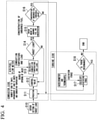
- FIG. 4 is a process flowchart showing ignition control of the combustor in the first embodiment of the present invention.
- the prediction unit 11 obtains setting of a target load (Step S10).
- the prediction unit 11 (the calculation unit 112) predicts the number of ignition cans, the arrangement of ignition cans, and a combustion temperature according to the target load (Step S11) and outputs the number of ignition cans, the arrangement of ignition cans, and the combustion temperature to the control unit 12.
- the control unit 12 calculates a degree of opening of a valve corresponding to the combustion temperature for each of the combustors 3 and controls a degree of opening of the fuel control valve 6 (Step S12). Furthermore, the control unit 12 calculates a degree of opening of the IGV 1 and controls the degree of opening of the IGV 1. Subsequently, the determination unit 13 obtains the degree of opening of a valve calculated by the control unit 12 and a fuel flow rate and an air flow rate measured by various flow meters provided on an upstream side of the combustors 3 and calculates a prediction value of a combustion temperature and a prediction value of a load for each of the combustors 3 (Step S13).
- the determination unit 13 compares the prediction value of the load with a target load and determines whether the target load has been achieved (Step S14). When it is determined that the target load has not been achieved (Step S14; No), the control unit 12 calculates the degree of opening of the valve again. The control unit 12 repeatedly performs the adjustment of the degree of opening of the valve until the target load has been achieved. For example, when the target load has not been achieved, the degree of opening of the fuel control valve 6 increases so that the load increases and the fuel flow rate increases.
- the determination unit 13 notifies the prediction unit 11 of the calculated prediction value of the combustion temperature and the calculated prediction value of the load. These prediction values are accumulated in the storage unit 113 and used at the time of updating various models or performing prediction again.
- the determination unit 13 obtains a measured value of an amount of unburned fuel to be discharged (a concentration) measured by a concentration meter provided downstream of the combustors 3 (Step S15). The determination unit 13 determines whether the concentration of the unburned fuel is less than a predetermined threshold value (for example, less than 10 ppm) (Step S16). If it is determined that the concentration of the unburned fuel is equal to or higher than a threshold value (Step S16; No), the prediction unit 11 predicts the number of ignition cans, the arrangement of ignition cans, and the combustion temperature according to the target load again (Step S11). The prediction unit 11 repeatedly performs the prediction of the number of ignition cans, the arrangement of ignition cans, and the combustion temperature until the target load and a threshold value of an unburned fuel concentration have been achieved.
- a predetermined threshold value for example, less than 10 ppm
- the prediction unit 11 may perform adjustment such as increasing of a target combustion temperature or decreasing of a target load.
- the prediction unit 11 predicts the number of ignition cans, the arrangement of ignition cans, and the combustion temperature in which an output as close to the target load as possible can be ensured within a range in which the conditions of the amount of unburned fuel to be discharged can be achieved.
- the determination unit 13 calculates an excitation force from measurement results of an accelerometer, a thermocouple, and the like provided in the turbine 4 (Step S17).
- the determination unit 13 analyzes a vibration mode of the turbine 4 from the excitation force and determines whether resonance occurs (Step S18). For example, the determination unit 13 determines that the resonance occurs if the vibration of the turbine 4 based on the excitation force matches the natural frequency of the blades of the turbine 4 and an amplitude thereof is equal to or greater than a threshold value.
- Step S18 the prediction unit 11 determines the number of ignition cans, the arrangement of ignition cans, and the combustion temperature again. The prediction unit 11 repeatedly performs determination concerning the number of ignition cans, the arrangement of ignition cans, and the combustion temperature until the target load, the conditions of the amount of unburned fuel to be discharged, and the state in which resonance does not occur have been achieved.
- the prediction unit 11 may perform adjustment such as increasing of a target combustion temperature or decreasing of a target load.
- the prediction unit 11 predicts the number of ignition cans, the arrangement of ignition cans, and the combustion temperature in which an output as close to the target load as possible can be ensured within a range in which the conditions of the amount of unburned fuel to be discharged can be achieved and the resonance does not occur.
- the prediction unit 11 ends the prediction if a target load, a low amount of unburned fuel to be discharged, and a state in which resonance does not occur can be realized with the predicted number of ignition cans, arrangement of ignition cans, and combustion temperature. Thus, an appropriate combination of the combinations 3 to ignite and a combustion temperature are decided.
- the control device 10 ignites only a combustor 3 based on the prediction, performs control so that a combustion temperature of the combustor 3 which has ignited is a combustion temperature predicted by the prediction unit 11, and causes the gas turbine to operate in a state in which the remaining combustors 3 are extinguished.
- control device 10 determines a combination of ignition and an extinguishing of the combustors 3 according to a new target load by performing the above-described processing.
- a required number of combustors 3 ignite in accordance with the magnitude of a target load instead of coping with the fluctuations of the target load by increasing or decreasing a combustion temperature of each can using all of the cans of the combustors 3-1 to 3-16 as targets and are combusted at a combustion temperature at which an amount of unburned fuel to be discharged is equal to or lower than a threshold value.
- the other combustors 3 fully extinguish and do not have supply of a fuel. That is to say, a combination of combustors 3 in which combustion is performed at a temperature close to a rated combustion temperature and an extinguished combustor 3 copes with the fluctuations of a load.
- an unburned fuel can be kept low in the ignited combustor 3 and discharging of an unburned fuel can be prevented in the extinguished combustor 3.
- the prediction of the arrangement of ignition cans using the prediction unit 11 allows the combustors 3 to ignite or extinguish to be arranged asymmetrically, the effects of minimizing combustion vibration coupled with multiple cans can be expected.
- the combustor ignition control in this embodiment can be realized through software having the above-described function installed therein, there is no need to develop a new combustor and it is possible to also apply the combustor ignition control to existing gas turbines at low cost.
- the determination unit 13 transmits information concerning the degree of opening of the valve, the combustion temperature, the prediction value of the load, the measured value of the unburned fuel concentration, the presence or absence of resonance, and the like used at the time of determination to the prediction unit 11.
- the prediction unit 11 receives such information and uses the information for tuning of various models.
- Combustor ignition control in a second embodiment will be described below with reference to FIGS. 5 and 6 .
- FIG. 5 is a block diagram showing an example of a control device according to the second embodiment of the present invention.
- a control device 10a includes a prediction unit 11a, a control unit 12, and a determination unit 13.
- the prediction unit 11a includes a communication unit 111, a calculation unit 112, a storage unit 113, and a frequency detection unit 114.
- the communication unit 111 transmits and receives monitoring data and control information.
- the calculation unit 112 calculates the number of ignition cans, the arrangement of ignition cans, and a combustion temperature according to a target load.
- the frequency detection unit 114 counts an ignition frequency for each of the combustors 3 and determines whether there is no bias in ignition of some of the combustors 3.
- the storage unit 113 stores an ignition frequency for each of the combustors 3 in addition to prediction results of the number of ignition cans, the arrangement of ignition cans, and a combustion temperature predicted for each monitoring data and target load.
- the control unit 12 and the determination unit 13 are the same as in the first embodiment. A process of selecting a combustor 3 to ignite so that an ignition frequency is not biased will be described below with reference to FIG. 6 .
- FIG. 6 is a process flowchart showing ignition control of the combustor in the second embodiment of the present invention.
- the communication unit 111 obtains setting of a target load (Step S10).
- the calculation unit 112 predicts the number of ignition cans, the arrangement of ignition cans, and a combustion temperature according to a target load (Step S11) and outputs the number of ignition cans, the arrangement of ignition cans, and the combustion temperature to the frequency detection unit 114.
- the frequency detection unit 114 reads out and obtains an ignition frequency for each of the combustors 3 included in the arrangement from the storage unit 113 on the basis of prediction information concerning the arrangement of ignition cans (Step S115).
- the frequency detection unit 114 determines whether there is no bias in ignition frequencies of the selected combustors 3 (Step S116). When it is determined that there is a bias in the ignition frequencies between the selected combustors 3 (Step S116; No), the frequency detection unit 114 designates information concerning a combustor 3 having a high ignition frequency and instructs the prediction unit 11 to perform re-prediction.
- the ignition frequency is, for example, a cumulative value of the number of times of ignition so far.
- the ignition frequency may be the number of times of ignition in a predetermined period.
- the prediction unit 11 which has received a re-prediction instruction may, for example, replace a combustor 3 having the highest ignition frequency with a combustor 3 having the lowest ignition frequency and output a combination of the combustors 3 after the replacement and a combustion temperature as prediction information.
- the determination concerning whether the ignition frequency is high may be determined that an ignition frequency of these combustors 3 is high.
- a combustor 3 having a high ignition frequency may be determined as having a high ignition frequency.
- the frequency detection unit 114 When it is determined that there is no bias in the ignition frequencies (Step S116; Yes), the frequency detection unit 114 adds "1" to an ignition frequency of a combustor 3 which is an ignition target predicted by the calculation unit 112 and writes the ignition frequency after the addition to the storage unit 113. Moreover, the frequency detection unit 114 outputs the number of ignition cans, the arrangement of ignition cans, and a combustion temperature predicted by the calculation unit 112 to the control unit 12.
- the control unit 12 controls a degree of opening of a fuel control valve 6 corresponding to each of the combustors 3 on the basis of the combustion temperature (Step S12). Subsequently, the determination unit 13 calculates a combustion temperature for each of the combustors 3 and a prediction value of a load (Step S13). The determination unit 13 determines whether the prediction value of the load has reached a target load (Step S14). When it is determined that the target load has not been achieved (Step S14; No), the control unit 12 repeatedly performs adjustment for a degree of opening of a valve until the target load has been achieved.
- the determination unit 13 obtains an amount of unburned fuel to be discharged (a concentration) from a concentration meter (Step S15) and determines whether the amount of unburned fuel to be discharged is less than a threshold value (Step S16). When it is determined that the an amount of unburned fuel to be discharged is equal to or greater than a threshold value (Step S16; No), the prediction unit 11 repeatedly performs the determination of the number of ignition cans, the arrangement of ignition cans, and the combustion temperature until the target load and the conditions of the amount of unburned fuel to be discharged have been achieved.
- Step S16 If it is determined that the target load and the conditions of the amount of unburned fuel to be discharged have been achieved (Step S16; Yes), the determination unit 13 calculates an excitation force (Step S17) and determines whether resonance occurs in the turbine 4 (Step S18). When it is determined that resonance occurs (Step S18; Yes), the prediction unit 11 repeatedly performs the determination of the number of ignition cans, the arrangement of ignition cans, and the combustion temperature until the target load, the conditions of the amount of unburned fuel to be discharged, and a state in which resonance does not occur have been achieved.
- the calculation unit 112 may include a function of the frequency detection unit 114 and the number of ignition cans, the arrangement of ignition cans, and the combustion temperature may be predicted using a learned model or an algorithm in which the calculation unit 112 performs prediction in which a bias does not occur in the number of ignitions. For example, when 8 cans (3-5 to 3-12) ignite in the example of FIG.
- an algorithm in which a combination of the combustors 3-6 to 3-13 or the combustors 3-4 to 3-11 obtained by shifting one by one is selected may be used and an algorithm in which the combustors 3-1 to 3-4 and the combustor 3-13 to 3-16 which have extinguished this time are selected may be used.
- a combustor 3 having the highest ignition frequency regardless of a target load may be excluded from selection targets and the prediction unit 11 may predict the number of ignition cans, the arrangement of ignition cans, and the combustion temperature.
- FIG. 7 is a diagram showing an example of a hardware constitution of a control device according to each embodiment of the present invention.
- a computer 900 is, for example, a personal computer (PC) or a server terminal device which includes a CPU 901, a main storage device 902, a main storage device 902, an auxiliary storage device 903, an input/output interface 904, and a communication interface 905.
- the above-described control devices 10 and 10a are installed in the computer 900. Furthermore, an operation of each processing unit described above is stored in the auxiliary storage device 903 in the form of a program.
- the CPU 901 reads out a program from the auxiliary storage device 903, develops the program in the main storage device 902, and executes the above processing in accordance with the program. Furthermore, the CPU 901 secures a storage region corresponding to the storage unit 113 in the main storage device 902 in accordance with the program. In addition, the CPU 901 secures a storage region having data being processed stored therein in the auxiliary storage device 903 in accordance with the program.
- the auxiliary storage device 903 is an example of a non-transitory tangible medium.
- the non-transitory tangible medium include a magnetic disk, a magneto-optical disk, a compact disk (CD)-read only storage (ROM), a digital versatile disc (DVD)-ROM, a semiconductor storage, and the like connected via the input/output interface 904.
- the computer 900 which received the distributed program may develop the program in the main storage device 902 and execute the above processing.
- the program may be for realizing some of the above functions.
- the program may be a so-called difference file (difference program) in which the above functions are realized through a combination of the file (the program) with another program stored in the auxiliary storage device 903 in advance.
- the prediction unit 11 is an example of a predictor.
Landscapes
- Engineering & Computer Science (AREA)
- Chemical & Material Sciences (AREA)
- Combustion & Propulsion (AREA)
- Mechanical Engineering (AREA)
- General Engineering & Computer Science (AREA)
- Control Of Turbines (AREA)
Claims (12)
- Steuervorrichtung (10, 10a) für eine Gasturbine (4) mit einer Mehrzahl von Brennkammern (3), umfassend:eine Vorhersageeinheit (11, 11a), die konfiguriert ist, um die Anzahl und Anordnung der Brennkammern (3), die zum Erreichen einer Ziellast erforderlich sind, auf der Grundlage eines erlernten Modells zu bestimmen, in dem eine Beziehung zwischen einer Last und der Anzahl und Anordnung der zu zündenden Brennkammern (3) definiert ist; undeine Steuereinheit (12), die konfiguriert ist, um die von der Vorhersageeinheit (11, 11a) bestimmten Brennkammern (3) auszuwählen und zu zünden.
- Die Steuervorrichtung (10, 10a) nach Anspruch 1, wobeidas erlernte Modell konfiguriert ist, um eine Beziehung zwischen der Last und der Anzahl der zu zündenden Brennkammern (3), der Anordnung der Brennkammern (3) und einer Verbrennungstemperatur der Brennkammern (3) zu bestimmen, bei der eine Menge an unverbranntem Brennstoff, die ausgestoßen werden soll, gleich oder kleiner als ein vorbestimmter Schwellenwert ist,die Vorhersageeinheit (11, 11a) konfiguriert ist, um die Anzahl der Brennkammern (3), die Anordnung der Brennkammern (3) und die Verbrennungstemperatur der Brennkammern (3) entsprechend der Ziellast auf der Grundlage des erlernten Modells zu bestimmen, unddie Steuereinheit (12) konfiguriert ist, um eine Verbrennungstemperatur der ausgewählten Brennkammern (3) auf der Grundlage der von der Vorhersageeinheit (11, 11a) bestimmten Verbrennungstemperatur zu steuern.
- Die Steuervorrichtung (10, 10a) nach Anspruch 1 oder 2, wobei
die Steuereinheit (12) konfiguriert ist, um die Steuerung so durchzuführen, dass andere Brennkammern (3) als die ausgewählten Brennkammern (3) vollständig ausgelöscht werden. - Die Steuervorrichtung (10, 10a) nach einem der Ansprüche 1 bis 3, ferner umfassend:
eine Bestimmungseinheit (13), die konfiguriert ist, um zu bestimmen, ob eine Menge an unverbranntem Brennstoff, die ausgestoßen werden soll, gleich oder kleiner als ein vorbestimmter Wert für jeden der ausgewählten Brennkammern (3) ist. - Die Steuervorrichtung (10, 10a) nach Anspruch 4, wobei
die Bestimmungseinheit (13) konfiguriert ist, um das Vorhandensein oder Nichtvorhandensein einer Resonanz der Turbine (4) für jede der ausgewählten Brennkammern (3) zu bestimmen. - Die Steuervorrichtung (10, 10a) nach einem der Ansprüche 1 bis3 , wobei
die Vorhersageeinheit (11, 11a) konfiguriert ist, um die Menge an unverbranntem Brennstoff, die ausgestoßen werden soll, so zu minimieren, dass sie gleich oder kleiner als ein vorbestimmter Schwellenwert ist, während die Ziellast erreicht wird, und eine Kombination der Brennkammern (3) zu bestimmen, in der keine Resonanz der Turbine (4) auftritt. - Die Steuervorrichtung (10, 10a) nach einem der Ansprüche 1 bis 6, ferner umfassend:eine Frequenzerfassungseinheit (114), die konfiguriert ist, um eine Zündfrequenz für jede der Brennkammern (3) zu erfassen,wobei die Steuereinheit (12) konfiguriert ist, um die Brennkammern (3) so auszuwählen, dass die Vorspannung der von der Frequenzerfassungseinheit (114) erfassten Zündfrequenz in einen vorgegebenen Bereich fällt.
- Die Steuervorrichtung (10, 10a) nach einem der Ansprüche 1 bis 7, wobei
wenn eine erste Ziellast aufgebracht wird, ist die Steuereinheit (12) konfiguriert, um eine Kombination von Brennkammern (3) auszuwählen und zu zünden, die sich von derjenigen unterscheidet, die beim letzten Mal, als die erste Ziellast aufgebracht wurde, verwendet wurde. - Die Steuervorrichtung (10, 10a) nach einem der Ansprüche 1 bis 8, wobei
das erlernte Modell aus einer Mehrzahl von Vorhersagemodellen zusammengesetzt ist und die Mehrzahl von Vorhersagemodellen ein erstes Vorhersagemodell, in dem eine Leistung für jede der Brennkammern (3) vorhergesagt wird, und ein zweites Vorhersagemodell, in dem eine Kombination der Brennkammern (3), in der die Ziellast auf der Grundlage der Leistung für jede der Brennkammern (3) und einer Verbrennungstemperatur jeder der Brennkammern (3) erreicht wird, vorhergesagt wird, umfasst. - Eine Gasturbine (4), bestehend aus:einen Kompressor (2);eine Mehrzahl von Brennkammern (3);eine Turbine (4); unddie Steuervorrichtung (10, 10a) nach einem der Ansprüche 1 bis 9.
- Verfahren zur Steuerung einer Gasturbine (4) mit einer Mehrzahl von Brennkammern (3), umfassend:Bestimmung der Anzahl und Anordnung der Brennkammern (3), die zum Erreichen einer Ziellast erforderlich sind, auf der Grundlage eines erlernten Modells, in dem eine Beziehung zwischen einer Last und der Anzahl und Anordnung der zu zündenden Brennkammern (3) definiert ist; undAuswahl und Zündung der bei der Bestimmung der Anzahl und Anordnung der Brennkammern (3) ermittelten Brennkammern (3) auf der Grundlage der Ziellast.
- Ein Programm, das einen Computer, der zur Steuerung einer Gasturbine (4) mit einer Mehrzahl von Brennkammern (3) konfiguriert ist, zur Ausführung veranlasst:Bestimmung der Anzahl und Anordnung der Brennkammern (3), die zum Erreichen einer Ziellast erforderlich sind, auf der Grundlage eines erlernten Modells, in dem eine Beziehung zwischen einer Last und der Anzahl und Anordnung der zu zündenden Brennkammern (3) definiert ist; undAuswahl und Zündung der bei der Bestimmung der Anzahl und Anordnung der Brennkammern (3) ermittelten Brennkammern auf der Grundlage der Ziellast.
Applications Claiming Priority (1)
| Application Number | Priority Date | Filing Date | Title |
|---|---|---|---|
| JP2019109353A JP7231493B2 (ja) | 2019-06-12 | 2019-06-12 | 制御装置、ガスタービン、制御方法及びプログラム |
Publications (2)
| Publication Number | Publication Date |
|---|---|
| EP3751199A1 EP3751199A1 (de) | 2020-12-16 |
| EP3751199B1 true EP3751199B1 (de) | 2022-03-16 |
Family
ID=69571803
Family Applications (1)
| Application Number | Title | Priority Date | Filing Date |
|---|---|---|---|
| EP20156590.0A Active EP3751199B1 (de) | 2019-06-12 | 2020-02-11 | Steuerungsvorrichtung, gasturbine, steuerungsverfahren und programm |
Country Status (3)
| Country | Link |
|---|---|
| US (1) | US11359552B2 (de) |
| EP (1) | EP3751199B1 (de) |
| JP (1) | JP7231493B2 (de) |
Families Citing this family (5)
| Publication number | Priority date | Publication date | Assignee | Title |
|---|---|---|---|---|
| JP7348126B2 (ja) * | 2020-03-30 | 2023-09-20 | 三菱重工業株式会社 | 制御装置、制御入力決定方法、及び制御入力決定プログラム |
| US11333082B2 (en) * | 2020-06-12 | 2022-05-17 | General Electric Company | Systems and methods for determination of gas turbine fuel split for head end temperature control |
| CN118742722A (zh) * | 2022-02-25 | 2024-10-01 | 株式会社Ihi | 燃烧装置以及燃气轮机 |
| CN115573817B (zh) * | 2022-09-08 | 2025-08-29 | 中国联合重型燃气轮机技术有限公司 | 一种纯氢燃气轮机系统的控制方法和装置 |
| JP2025124976A (ja) * | 2024-02-15 | 2025-08-27 | 三菱重工業株式会社 | ガスタービンの運転方法及びガスタービンの制御装置 |
Family Cites Families (10)
| Publication number | Priority date | Publication date | Assignee | Title |
|---|---|---|---|---|
| JPH08246903A (ja) * | 1995-03-07 | 1996-09-24 | Hitachi Ltd | ガスタービン発電装置およびその制御方法 |
| US8122725B2 (en) | 2007-11-01 | 2012-02-28 | General Electric Company | Methods and systems for operating gas turbine engines |
| CH700796A1 (de) * | 2009-04-01 | 2010-10-15 | Alstom Technology Ltd | Verfahren zum CO-emissionsarmen Betrieb einer Gasturbine mit sequentieller Verbrennung und Gasturbine mit verbessertem Teillast- Emissionsverhalten. |
| EP2600063A3 (de) | 2013-02-19 | 2014-05-07 | Alstom Technology Ltd | Verfahren zum Betrieb einer Gasturbine mit gestufter und/oder sequentieller Verbrennung |
| DE102013205356B4 (de) | 2013-03-26 | 2016-07-07 | Siemens Aktiengesellschaft | Verfahren zur rechnergestützten Steuerung und/oder Regelung eines technischen Systems |
| EP2835516A1 (de) * | 2013-08-08 | 2015-02-11 | Alstom Technology Ltd | Gasturbine mit verbessertem Teillast-Emissionsverhalten |
| EP2857658A1 (de) | 2013-10-01 | 2015-04-08 | Alstom Technology Ltd | Gasturbine mit einer sequentiellen Brennanordnung |
| EP2902606B1 (de) | 2014-01-31 | 2019-01-02 | Ansaldo Energia IP UK Limited | Verfahren zum Betreiben einer Gasturbine in Teillast |
| JP6181589B2 (ja) | 2014-03-31 | 2017-08-16 | 株式会社Ihi | 計測値解析装置及び計測値解析方法 |
| US20170328567A1 (en) * | 2016-05-11 | 2017-11-16 | United Technologies Corporation | Multivariable fuel control and estimator (mfce) for preventing combustor blowout |
-
2019
- 2019-06-12 JP JP2019109353A patent/JP7231493B2/ja active Active
-
2020
- 2020-02-11 US US16/787,699 patent/US11359552B2/en active Active
- 2020-02-11 EP EP20156590.0A patent/EP3751199B1/de active Active
Also Published As
| Publication number | Publication date |
|---|---|
| US11359552B2 (en) | 2022-06-14 |
| US20200392908A1 (en) | 2020-12-17 |
| JP7231493B2 (ja) | 2023-03-01 |
| JP2020200807A (ja) | 2020-12-17 |
| EP3751199A1 (de) | 2020-12-16 |
Similar Documents
| Publication | Publication Date | Title |
|---|---|---|
| EP3751199B1 (de) | Steuerungsvorrichtung, gasturbine, steuerungsverfahren und programm | |
| US8396643B2 (en) | Gas turbine control device and gas turbine system | |
| JP5346190B2 (ja) | 燃料正規化出力応答を利用したガスタービン燃焼消焔検出のための方法及びシステム | |
| RU2540210C2 (ru) | Способ управления режимом работы газовой турбины на основе температуры выхлопного газа и газовая турбина | |
| CN101368514B (zh) | 用基于事件的作用减弱不希望的燃气轮机瞬态响应的方法 | |
| US9803560B2 (en) | Dynamic tuning of a gas turbine engine to detect and prevent lean blowout | |
| KR101520240B1 (ko) | 밸브 제어 장치, 가스 터빈, 및 밸브 제어 방법 | |
| US12012905B2 (en) | Control device, gas turbine, control method, and program | |
| CN102454486A (zh) | 防止在瞬态操作期间的燃烧不稳定性的方法和系统 | |
| JP2012207564A (ja) | ガスタービンの制御装置 | |
| US20140182297A1 (en) | Gas turbine and method of controlling a gas turbine at part-load condition | |
| EP1746347A2 (de) | Verfahren und System zum Betrieb einer mehrstufigen Brennkammer | |
| EP3061945B1 (de) | Verfahren zur steuerung des betriebs einer gasturbine mit sequenzieller verbrennung | |
| CN107850306A (zh) | 具有时间序列与旁通滤波器的燃烧智能控制及相应系统 | |
| JP7055894B2 (ja) | ガスタービン用のバーナー及びバーナーの運転方法 | |
| WO2013126279A1 (en) | Optimization of gas turbine combustion systems low load performance on simple cycle and heat recovery steam generator applications | |
| EP3330615B1 (de) | Modelllose automatische regelung der verbrennungsdynamik | |
| US20250027650A1 (en) | Gas turbine control device, gas turbine control method, and storage medium | |
| EP2959139B1 (de) | Optimierung von gasturbinenverbrennungssystemen mit schwacher ladeleistung in einem einfachen kreislauf und wärmerückgewinnungs-dampferzeugeranwendungen | |
| Singla et al. | Advanced Automated GT26 Combustion Tuning for Increased Operational Flexibility and Performance | |
| JP2014169701A (ja) | ガスタービンの制御方法及びガスタービンの燃空比設定方法 |
Legal Events
| Date | Code | Title | Description |
|---|---|---|---|
| PUAI | Public reference made under article 153(3) epc to a published international application that has entered the european phase |
Free format text: ORIGINAL CODE: 0009012 |
|
| STAA | Information on the status of an ep patent application or granted ep patent |
Free format text: STATUS: THE APPLICATION HAS BEEN PUBLISHED |
|
| AK | Designated contracting states |
Kind code of ref document: A1 Designated state(s): AL AT BE BG CH CY CZ DE DK EE ES FI FR GB GR HR HU IE IS IT LI LT LU LV MC MK MT NL NO PL PT RO RS SE SI SK SM TR |
|
| AX | Request for extension of the european patent |
Extension state: BA ME |
|
| STAA | Information on the status of an ep patent application or granted ep patent |
Free format text: STATUS: REQUEST FOR EXAMINATION WAS MADE |
|
| 17P | Request for examination filed |
Effective date: 20210406 |
|
| RBV | Designated contracting states (corrected) |
Designated state(s): AL AT BE BG CH CY CZ DE DK EE ES FI FR GB GR HR HU IE IS IT LI LT LU LV MC MK MT NL NO PL PT RO RS SE SI SK SM TR |
|
| GRAP | Despatch of communication of intention to grant a patent |
Free format text: ORIGINAL CODE: EPIDOSNIGR1 |
|
| RIC1 | Information provided on ipc code assigned before grant |
Ipc: F23N 1/00 20060101AFI20210802BHEP |
|
| STAA | Information on the status of an ep patent application or granted ep patent |
Free format text: STATUS: GRANT OF PATENT IS INTENDED |
|
| INTG | Intention to grant announced |
Effective date: 20210909 |
|
| GRAS | Grant fee paid |
Free format text: ORIGINAL CODE: EPIDOSNIGR3 |
|
| GRAA | (expected) grant |
Free format text: ORIGINAL CODE: 0009210 |
|
| STAA | Information on the status of an ep patent application or granted ep patent |
Free format text: STATUS: THE PATENT HAS BEEN GRANTED |
|
| AK | Designated contracting states |
Kind code of ref document: B1 Designated state(s): AL AT BE BG CH CY CZ DE DK EE ES FI FR GB GR HR HU IE IS IT LI LT LU LV MC MK MT NL NO PL PT RO RS SE SI SK SM TR |
|
| REG | Reference to a national code |
Ref country code: GB Ref legal event code: FG4D |
|
| REG | Reference to a national code |
Ref country code: CH Ref legal event code: EP Ref country code: DE Ref legal event code: R096 Ref document number: 602020002187 Country of ref document: DE |
|
| REG | Reference to a national code |
Ref country code: IE Ref legal event code: FG4D |
|
| REG | Reference to a national code |
Ref country code: AT Ref legal event code: REF Ref document number: 1476139 Country of ref document: AT Kind code of ref document: T Effective date: 20220415 |
|
| REG | Reference to a national code |
Ref country code: LT Ref legal event code: MG9D |
|
| REG | Reference to a national code |
Ref country code: NL Ref legal event code: MP Effective date: 20220316 |
|
| PG25 | Lapsed in a contracting state [announced via postgrant information from national office to epo] |
Ref country code: SE Free format text: LAPSE BECAUSE OF FAILURE TO SUBMIT A TRANSLATION OF THE DESCRIPTION OR TO PAY THE FEE WITHIN THE PRESCRIBED TIME-LIMIT Effective date: 20220316 Ref country code: RS Free format text: LAPSE BECAUSE OF FAILURE TO SUBMIT A TRANSLATION OF THE DESCRIPTION OR TO PAY THE FEE WITHIN THE PRESCRIBED TIME-LIMIT Effective date: 20220316 Ref country code: NO Free format text: LAPSE BECAUSE OF FAILURE TO SUBMIT A TRANSLATION OF THE DESCRIPTION OR TO PAY THE FEE WITHIN THE PRESCRIBED TIME-LIMIT Effective date: 20220616 Ref country code: LT Free format text: LAPSE BECAUSE OF FAILURE TO SUBMIT A TRANSLATION OF THE DESCRIPTION OR TO PAY THE FEE WITHIN THE PRESCRIBED TIME-LIMIT Effective date: 20220316 Ref country code: HR Free format text: LAPSE BECAUSE OF FAILURE TO SUBMIT A TRANSLATION OF THE DESCRIPTION OR TO PAY THE FEE WITHIN THE PRESCRIBED TIME-LIMIT Effective date: 20220316 Ref country code: BG Free format text: LAPSE BECAUSE OF FAILURE TO SUBMIT A TRANSLATION OF THE DESCRIPTION OR TO PAY THE FEE WITHIN THE PRESCRIBED TIME-LIMIT Effective date: 20220616 |
|
| REG | Reference to a national code |
Ref country code: AT Ref legal event code: MK05 Ref document number: 1476139 Country of ref document: AT Kind code of ref document: T Effective date: 20220316 |
|
| PG25 | Lapsed in a contracting state [announced via postgrant information from national office to epo] |
Ref country code: LV Free format text: LAPSE BECAUSE OF FAILURE TO SUBMIT A TRANSLATION OF THE DESCRIPTION OR TO PAY THE FEE WITHIN THE PRESCRIBED TIME-LIMIT Effective date: 20220316 Ref country code: GR Free format text: LAPSE BECAUSE OF FAILURE TO SUBMIT A TRANSLATION OF THE DESCRIPTION OR TO PAY THE FEE WITHIN THE PRESCRIBED TIME-LIMIT Effective date: 20220617 Ref country code: FI Free format text: LAPSE BECAUSE OF FAILURE TO SUBMIT A TRANSLATION OF THE DESCRIPTION OR TO PAY THE FEE WITHIN THE PRESCRIBED TIME-LIMIT Effective date: 20220316 |
|
| PG25 | Lapsed in a contracting state [announced via postgrant information from national office to epo] |
Ref country code: NL Free format text: LAPSE BECAUSE OF FAILURE TO SUBMIT A TRANSLATION OF THE DESCRIPTION OR TO PAY THE FEE WITHIN THE PRESCRIBED TIME-LIMIT Effective date: 20220316 |
|
| PG25 | Lapsed in a contracting state [announced via postgrant information from national office to epo] |
Ref country code: SM Free format text: LAPSE BECAUSE OF FAILURE TO SUBMIT A TRANSLATION OF THE DESCRIPTION OR TO PAY THE FEE WITHIN THE PRESCRIBED TIME-LIMIT Effective date: 20220316 Ref country code: SK Free format text: LAPSE BECAUSE OF FAILURE TO SUBMIT A TRANSLATION OF THE DESCRIPTION OR TO PAY THE FEE WITHIN THE PRESCRIBED TIME-LIMIT Effective date: 20220316 Ref country code: RO Free format text: LAPSE BECAUSE OF FAILURE TO SUBMIT A TRANSLATION OF THE DESCRIPTION OR TO PAY THE FEE WITHIN THE PRESCRIBED TIME-LIMIT Effective date: 20220316 Ref country code: PT Free format text: LAPSE BECAUSE OF FAILURE TO SUBMIT A TRANSLATION OF THE DESCRIPTION OR TO PAY THE FEE WITHIN THE PRESCRIBED TIME-LIMIT Effective date: 20220718 Ref country code: ES Free format text: LAPSE BECAUSE OF FAILURE TO SUBMIT A TRANSLATION OF THE DESCRIPTION OR TO PAY THE FEE WITHIN THE PRESCRIBED TIME-LIMIT Effective date: 20220316 Ref country code: EE Free format text: LAPSE BECAUSE OF FAILURE TO SUBMIT A TRANSLATION OF THE DESCRIPTION OR TO PAY THE FEE WITHIN THE PRESCRIBED TIME-LIMIT Effective date: 20220316 Ref country code: CZ Free format text: LAPSE BECAUSE OF FAILURE TO SUBMIT A TRANSLATION OF THE DESCRIPTION OR TO PAY THE FEE WITHIN THE PRESCRIBED TIME-LIMIT Effective date: 20220316 Ref country code: AT Free format text: LAPSE BECAUSE OF FAILURE TO SUBMIT A TRANSLATION OF THE DESCRIPTION OR TO PAY THE FEE WITHIN THE PRESCRIBED TIME-LIMIT Effective date: 20220316 |
|
| PG25 | Lapsed in a contracting state [announced via postgrant information from national office to epo] |
Ref country code: PL Free format text: LAPSE BECAUSE OF FAILURE TO SUBMIT A TRANSLATION OF THE DESCRIPTION OR TO PAY THE FEE WITHIN THE PRESCRIBED TIME-LIMIT Effective date: 20220316 Ref country code: IS Free format text: LAPSE BECAUSE OF FAILURE TO SUBMIT A TRANSLATION OF THE DESCRIPTION OR TO PAY THE FEE WITHIN THE PRESCRIBED TIME-LIMIT Effective date: 20220716 Ref country code: AL Free format text: LAPSE BECAUSE OF FAILURE TO SUBMIT A TRANSLATION OF THE DESCRIPTION OR TO PAY THE FEE WITHIN THE PRESCRIBED TIME-LIMIT Effective date: 20220316 |
|
| REG | Reference to a national code |
Ref country code: DE Ref legal event code: R097 Ref document number: 602020002187 Country of ref document: DE |
|
| PLBE | No opposition filed within time limit |
Free format text: ORIGINAL CODE: 0009261 |
|
| STAA | Information on the status of an ep patent application or granted ep patent |
Free format text: STATUS: NO OPPOSITION FILED WITHIN TIME LIMIT |
|
| PG25 | Lapsed in a contracting state [announced via postgrant information from national office to epo] |
Ref country code: DK Free format text: LAPSE BECAUSE OF FAILURE TO SUBMIT A TRANSLATION OF THE DESCRIPTION OR TO PAY THE FEE WITHIN THE PRESCRIBED TIME-LIMIT Effective date: 20220316 |
|
| 26N | No opposition filed |
Effective date: 20221219 |
|
| PG25 | Lapsed in a contracting state [announced via postgrant information from national office to epo] |
Ref country code: SI Free format text: LAPSE BECAUSE OF FAILURE TO SUBMIT A TRANSLATION OF THE DESCRIPTION OR TO PAY THE FEE WITHIN THE PRESCRIBED TIME-LIMIT Effective date: 20220316 |
|
| PG25 | Lapsed in a contracting state [announced via postgrant information from national office to epo] |
Ref country code: IT Free format text: LAPSE BECAUSE OF FAILURE TO SUBMIT A TRANSLATION OF THE DESCRIPTION OR TO PAY THE FEE WITHIN THE PRESCRIBED TIME-LIMIT Effective date: 20220316 |
|
| PG25 | Lapsed in a contracting state [announced via postgrant information from national office to epo] |
Ref country code: MC Free format text: LAPSE BECAUSE OF FAILURE TO SUBMIT A TRANSLATION OF THE DESCRIPTION OR TO PAY THE FEE WITHIN THE PRESCRIBED TIME-LIMIT Effective date: 20220316 |
|
| REG | Reference to a national code |
Ref country code: CH Ref legal event code: PL |
|
| REG | Reference to a national code |
Ref country code: BE Ref legal event code: MM Effective date: 20230228 |
|
| PG25 | Lapsed in a contracting state [announced via postgrant information from national office to epo] |
Ref country code: LU Free format text: LAPSE BECAUSE OF NON-PAYMENT OF DUE FEES Effective date: 20230211 Ref country code: LI Free format text: LAPSE BECAUSE OF NON-PAYMENT OF DUE FEES Effective date: 20230228 Ref country code: CH Free format text: LAPSE BECAUSE OF NON-PAYMENT OF DUE FEES Effective date: 20230228 |
|
| REG | Reference to a national code |
Ref country code: IE Ref legal event code: MM4A |
|
| PG25 | Lapsed in a contracting state [announced via postgrant information from national office to epo] |
Ref country code: IE Free format text: LAPSE BECAUSE OF NON-PAYMENT OF DUE FEES Effective date: 20230211 Ref country code: FR Free format text: LAPSE BECAUSE OF NON-PAYMENT OF DUE FEES Effective date: 20230228 |
|
| PG25 | Lapsed in a contracting state [announced via postgrant information from national office to epo] |
Ref country code: BE Free format text: LAPSE BECAUSE OF NON-PAYMENT OF DUE FEES Effective date: 20230228 |
|
| GBPC | Gb: european patent ceased through non-payment of renewal fee |
Effective date: 20240211 |
|
| PG25 | Lapsed in a contracting state [announced via postgrant information from national office to epo] |
Ref country code: GB Free format text: LAPSE BECAUSE OF NON-PAYMENT OF DUE FEES Effective date: 20240211 |
|
| PG25 | Lapsed in a contracting state [announced via postgrant information from national office to epo] |
Ref country code: GB Free format text: LAPSE BECAUSE OF NON-PAYMENT OF DUE FEES Effective date: 20240211 |
|
| PG25 | Lapsed in a contracting state [announced via postgrant information from national office to epo] |
Ref country code: CY Free format text: LAPSE BECAUSE OF FAILURE TO SUBMIT A TRANSLATION OF THE DESCRIPTION OR TO PAY THE FEE WITHIN THE PRESCRIBED TIME-LIMIT; INVALID AB INITIO Effective date: 20200211 |
|
| PG25 | Lapsed in a contracting state [announced via postgrant information from national office to epo] |
Ref country code: HU Free format text: LAPSE BECAUSE OF FAILURE TO SUBMIT A TRANSLATION OF THE DESCRIPTION OR TO PAY THE FEE WITHIN THE PRESCRIBED TIME-LIMIT; INVALID AB INITIO Effective date: 20200211 |
|
| PG25 | Lapsed in a contracting state [announced via postgrant information from national office to epo] |
Ref country code: TR Free format text: LAPSE BECAUSE OF FAILURE TO SUBMIT A TRANSLATION OF THE DESCRIPTION OR TO PAY THE FEE WITHIN THE PRESCRIBED TIME-LIMIT Effective date: 20220316 |
|
| PGFP | Annual fee paid to national office [announced via postgrant information from national office to epo] |
Ref country code: DE Payment date: 20251230 Year of fee payment: 7 |