EP3751123A1 - Couvercle de cylindre pour un cylindre d'un gros moteur diesel et procédé de réparation d'un couvercle de cylindre - Google Patents
Couvercle de cylindre pour un cylindre d'un gros moteur diesel et procédé de réparation d'un couvercle de cylindre Download PDFInfo
- Publication number
- EP3751123A1 EP3751123A1 EP19180334.5A EP19180334A EP3751123A1 EP 3751123 A1 EP3751123 A1 EP 3751123A1 EP 19180334 A EP19180334 A EP 19180334A EP 3751123 A1 EP3751123 A1 EP 3751123A1
- Authority
- EP
- European Patent Office
- Prior art keywords
- combustion chamber
- nozzle channel
- fuel
- cylinder cover
- axis
- Prior art date
- Legal status (The legal status is an assumption and is not a legal conclusion. Google has not performed a legal analysis and makes no representation as to the accuracy of the status listed.)
- Withdrawn
Links
Images


Classifications
-
- F—MECHANICAL ENGINEERING; LIGHTING; HEATING; WEAPONS; BLASTING
- F02—COMBUSTION ENGINES; HOT-GAS OR COMBUSTION-PRODUCT ENGINE PLANTS
- F02F—CYLINDERS, PISTONS OR CASINGS, FOR COMBUSTION ENGINES; ARRANGEMENTS OF SEALINGS IN COMBUSTION ENGINES
- F02F1/00—Cylinders; Cylinder heads
- F02F1/24—Cylinder heads
- F02F1/242—Arrangement of spark plugs or injectors
-
- B—PERFORMING OPERATIONS; TRANSPORTING
- B23—MACHINE TOOLS; METAL-WORKING NOT OTHERWISE PROVIDED FOR
- B23P—METAL-WORKING NOT OTHERWISE PROVIDED FOR; COMBINED OPERATIONS; UNIVERSAL MACHINE TOOLS
- B23P6/00—Restoring or reconditioning objects
- B23P6/02—Pistons or cylinders
-
- F—MECHANICAL ENGINEERING; LIGHTING; HEATING; WEAPONS; BLASTING
- F02—COMBUSTION ENGINES; HOT-GAS OR COMBUSTION-PRODUCT ENGINE PLANTS
- F02B—INTERNAL-COMBUSTION PISTON ENGINES; COMBUSTION ENGINES IN GENERAL
- F02B25/00—Engines characterised by using fresh charge for scavenging cylinders
- F02B25/02—Engines characterised by using fresh charge for scavenging cylinders using unidirectional scavenging
- F02B25/04—Engines having ports both in cylinder head and in cylinder wall near bottom of piston stroke
-
- F—MECHANICAL ENGINEERING; LIGHTING; HEATING; WEAPONS; BLASTING
- F02—COMBUSTION ENGINES; HOT-GAS OR COMBUSTION-PRODUCT ENGINE PLANTS
- F02F—CYLINDERS, PISTONS OR CASINGS, FOR COMBUSTION ENGINES; ARRANGEMENTS OF SEALINGS IN COMBUSTION ENGINES
- F02F7/00—Casings, e.g. crankcases or frames
- F02F7/0021—Construction
- F02F7/0024—Casings for larger engines
-
- F—MECHANICAL ENGINEERING; LIGHTING; HEATING; WEAPONS; BLASTING
- F02—COMBUSTION ENGINES; HOT-GAS OR COMBUSTION-PRODUCT ENGINE PLANTS
- F02B—INTERNAL-COMBUSTION PISTON ENGINES; COMBUSTION ENGINES IN GENERAL
- F02B75/00—Other engines
- F02B75/02—Engines characterised by their cycles, e.g. six-stroke
- F02B2075/022—Engines characterised by their cycles, e.g. six-stroke having less than six strokes per cycle
- F02B2075/025—Engines characterised by their cycles, e.g. six-stroke having less than six strokes per cycle two
-
- F—MECHANICAL ENGINEERING; LIGHTING; HEATING; WEAPONS; BLASTING
- F02—COMBUSTION ENGINES; HOT-GAS OR COMBUSTION-PRODUCT ENGINE PLANTS
- F02F—CYLINDERS, PISTONS OR CASINGS, FOR COMBUSTION ENGINES; ARRANGEMENTS OF SEALINGS IN COMBUSTION ENGINES
- F02F1/00—Cylinders; Cylinder heads
- F02F1/24—Cylinder heads
- F02F2001/241—Cylinder heads specially adapted to pent roof shape of the combustion chamber
-
- F—MECHANICAL ENGINEERING; LIGHTING; HEATING; WEAPONS; BLASTING
- F02—COMBUSTION ENGINES; HOT-GAS OR COMBUSTION-PRODUCT ENGINE PLANTS
- F02F—CYLINDERS, PISTONS OR CASINGS, FOR COMBUSTION ENGINES; ARRANGEMENTS OF SEALINGS IN COMBUSTION ENGINES
- F02F7/00—Casings, e.g. crankcases or frames
- F02F2007/0097—Casings, e.g. crankcases or frames for large diesel engines
-
- F—MECHANICAL ENGINEERING; LIGHTING; HEATING; WEAPONS; BLASTING
- F02—COMBUSTION ENGINES; HOT-GAS OR COMBUSTION-PRODUCT ENGINE PLANTS
- F02F—CYLINDERS, PISTONS OR CASINGS, FOR COMBUSTION ENGINES; ARRANGEMENTS OF SEALINGS IN COMBUSTION ENGINES
- F02F2200/00—Manufacturing
Definitions
- the invention relates to a cylinder cover for a cylinder of a large diesel engine and a method for repairing a cylinder cover according to the preamble of the independent claim of the respective category.
- Large diesel engines which can be designed as two-stroke or four-stroke machines, for example as longitudinally flushed two-stroke large diesel engines, are often used as drive units for ships or also in stationary operation, e.g. used to drive large generators to generate electrical energy.
- the motors usually run continuously for considerable periods of time, which places high demands on operational reliability and availability. Therefore, long maintenance intervals, low wear and tear and economical use of the operating materials are central criteria for the operator.
- Large diesel engines typically have cylinders with an internal diameter (bore) of at least 200 mm.
- large engines with a bore of up to 960 mm or even more are used.
- liquid fuels as known alternatives to heavy oil are other heavy hydrocarbons, which remain in particular as residues in the refinery of petroleum, alcohols, in particular methanol or ethanol, gasoline, diesel, or emulsions or suspensions. So it is e.g. B. known as MSAR (Multiphase Superfine Atomized Residue) to use emulsions as fuel.
- MSAR Multiphase Superfine Atomized Residue
- a well-known suspension is that made from coal dust and water, which is also used as fuel for large engines.
- Natural gases such as LNG (liquefied natural gas) are known as gaseous fuels.
- a known embodiment of a large diesel engine that can be operated with two different fuels is the type of engine for which the term “dual-fuel engine” is used nowadays.
- These engines can be operated on the one hand in a gas mode in which a gaseous fuel, e.g. natural gas or methane, is introduced into the combustion chamber for combustion, and on the other hand in a liquid mode in which a liquid fuel such as heavy oil or another liquid fuel burns in the same engine can be.
- These big diesel engines can be both two-stroke and four-stroke engines, especially longitudinally flushed two-stroke large diesel engines.
- large diesel engine means engines which can be operated at least in diesel mode.
- large diesel engine also includes those dual-fuel or multi-fuel large engines which, in addition to diesel operation, can also be operated in another operation, for example Otto operation.
- a large diesel engine comprises at least one cylinder, but usually several cylinders, with a piston being provided in each cylinder, which piston is arranged to be movable back and forth between a top dead center and a bottom dead center. Furthermore, each cylinder comprises a cylinder cover which, together with the piston, delimits a combustion chamber. During the During operation, a fuel is introduced into the combustion chamber which, depending on the operating mode, is externally ignited or ignites itself when the piston is near top dead center.
- a bore is usually provided in the cylinder cover, which extends into the combustion chamber.
- a seat is provided on which the fuel injector is seated, d. H. downstream of the seat surface, the bore is designed as a nozzle channel with a significantly smaller diameter.
- the fuel injection nozzle has a nozzle head at its end through which the fuel is injected. When the fuel injection nozzle is arranged in the bore, the nozzle head extends through the nozzle channel into the combustion chamber. This means that the nozzle head protrudes beyond the wall that delimits the combustion chamber.
- the nozzle head has a plurality of nozzle holes through which the fuel is injected into the combustion chamber in a manner known per se.
- the fuel injection nozzle is usually arranged in such a way that it extends obliquely to the cylinder axis of the cylinder or to the combustion chamber axis, the combustion chamber axis usually coinciding with the cylinder axis.
- the longitudinal axis of the fuel injection nozzle then forms an acute angle with the cylinder axis. Due to the severely limited space, it is generally not possible to arrange the fuel injection nozzle (s) at any desired angle to the cylinder axis, but the angular range that can be realized is severely restricted.
- a cylinder cover for a cylinder of a large diesel engine having at least one fuel bore for receiving a fuel injection nozzle and a combustion chamber surface for delimiting a combustion chamber which has a combustion chamber axis, the fuel bore extending in the direction of a fuel axis and into the The combustion chamber surface opens out, with a seat surface for the fuel injector being provided in the fuel bore, the seat surface having an axis of symmetry which coincides with the fuel axis, the seat surface being connected to the combustion chamber surface by a nozzle channel, the nozzle channel having a length ratio which corresponds to the ratio from a maximum length of the nozzle channel and a minimum length of the nozzle channel, and wherein the length ratio is at most equal to two.
- the varying length of the nozzle channel which connects the seating surface of the fuel bore with the combustion chamber, over the circumference of the nozzle channel, represents a major cause of crack formation in the wall of the combustion chamber.
- the seat surface in the fuel bore, on which the fuel injection nozzle rests has a relatively large changing distance from the combustion chamber over its circumference. Seen along the circumference of the seat surface, the seat surface is spaced differently from the combustion chamber. As a result, the nozzle channel has a significantly shorter length at some points on its circumference than at others.
- the invention now proposes reducing these changes in the length of the nozzle channel, such that the length ratio, which is the ratio of the maximum and the minimum length of the nozzle channel, is at most two. As a result of this reduction in the change in the length of the nozzle channel seen over its circumference, the formation of cracks in the combustion chamber can at least be significantly reduced.
- the ratio of the maximum length and the minimum length is equal to one, that is to say the maximum and the minimum length are identical, so that the nozzle channel has a constant length over its entire circumference. In many applications, however, this ideal case cannot be implemented for practical reasons. It has been shown, however, that at least a very good reduction, if not even a complete suppression of crack formation, can be achieved, in particular, when the length ratio is at most 1.5 and preferably less than 1.4.
- a particularly preferred embodiment for reducing the length ratio is to provide a bulge-shaped elevation on the combustion chamber surface which delimits part of the nozzle channel. This measure allows the nozzle channel to be along those areas Extend its circumference, in which the nozzle channel would be shorter without the elevation than in other areas. In this embodiment, the nozzle channel is extended in those areas in which it has the smallest length without the elevation.
- the elevation preferably delimits the nozzle channel on its side facing the combustion chamber axis, because this area is usually the area where the distance between the seat surface and the combustion chamber is smallest.
- the elevation is preferably designed in such a way that it reduces the length ratio to a predefinable value.
- the minimum value for the aspect ratio is equal to one.
- the length ratio is set to a value greater than one, for example to 1.4.
- the respective desired value for the length ratio can then be realized through the geometric dimensions of the elevation.
- the elevation is primarily intended to reduce or compensate for the difference between the maximum length of the nozzle channel without an elevation and the minimum length of the nozzle channel without an elevation, it is advantageous if the elevation, viewed in the circumferential direction of the nozzle channel, extends at most over half the circumference of the nozzle channel .
- the height of the elevation changes as seen in the circumferential direction of the nozzle channel.
- the height of the elevation here means the extension of the elevation perpendicular to the combustion chamber surface.
- the elevation has a maximum width that is at least as large as half the radius of the nozzle channel and preferably at least as large as the radius of the nozzle channel.
- the width of the elevation is understood to mean the dimension of how far the elevation in the combustion chamber surface extends away from the nozzle channel.
- Another preferred embodiment for reducing the length ratio is to provide a recess in the combustion chamber surface into which the nozzle channel opens.
- the nozzle channel is shortened in those areas in which it has the greatest length without the recess.
- the recess is preferably designed in such a way that it reduces the length ratio to a predefinable value.
- the minimum value for the aspect ratio is equal to one.
- the length ratio is set to a value greater than one, for example 1.5.
- the respective desired value for the length ratio can then be realized through the geometric dimensions of the recess.
- the recess is primarily intended to reduce or compensate for the difference between the maximum length of the nozzle channel without a recess and the minimum length of the nozzle channel without a recess, it is advantageous if the recess is seen in the circumferential direction of the nozzle channel, at least over half the circumference of the nozzle channel extends.
- the recess it is also possible for the recess to extend over the entire circumference of the nozzle channel as seen in the circumferential direction of the nozzle channel.
- the depth of the recess changes, viewed in the circumferential direction of the nozzle channel, in such a way that the maximum length of the nozzle channel is at most twice as great as the minimum length of the nozzle channel.
- the recess has to be provided over the entire circumference of the nozzle channel the advantage that sharp edges or very thin areas at the boundary of the nozzle channel can be avoided.
- the recess extends along at least part of the circumference of the nozzle channel, the recess has a radius. This radius is preferably at least twice as large as the radius of the nozzle channel.
- the invention also proposes a method for repairing a cylinder cover of a cylinder of a large diesel engine, the cylinder cover having at least one fuel bore for receiving a fuel injection nozzle, and a combustion chamber surface for delimiting a combustion chamber which has a combustion chamber axis, the fuel bore extending in the direction of a Fuel axis extends and opens into the combustion chamber surface, wherein a seat surface for the fuel injector is provided in the fuel bore, the seat surface having an axis of symmetry which coincides with the fuel axis, and wherein the seat surface is connected to the combustion chamber surface by a nozzle channel.
- the method is particularly characterized in that the combustion chamber surface of the cylinder cover is machined in such a way that the nozzle channel has an length ratio which is at most equal to two, the length ratio being the ratio of a maximum length of the nozzle channel and a minimum length of the nozzle channel.
- the finding, which is essential for the invention, that the varying length of the nozzle channel, which connects the seat surface of the fuel bore with the combustion chamber, represents an essential cause for the formation of cracks in the wall of the combustion chamber over the circumference of the nozzle channel, can also be advantageous for the repair a cylinder cover of a large diesel engine.
- the combustion chamber surface is then processed in such a way that the repaired cylinder cover embodies a cylinder cover according to the invention.
- the length ratio is preferably changed in that a bead-like elevation is applied to the combustion chamber surface, or in that a recess is provided in the combustion chamber surface.
- the invention also proposes a large diesel engine, in particular a longitudinally flushed two-stroke large diesel engine, with at least one cylinder, the cylinder having a cylinder cover which is designed according to the invention or which is repaired using a method according to the invention.
- large diesel engine refers to engines that are usually used as main drive units for ships or also in stationary operation, e.g. be used to drive large generators to generate electrical energy.
- the cylinders of a large diesel engine each have an inside diameter (bore) that is at least about 200 mm.
- flushed means that the flushing or charge air is introduced into the cylinder in the area of the lower end.
- this exemplary embodiment of the large diesel engine can be operated in a liquid mode in which only a liquid fuel is injected into a combustion chamber of a cylinder.
- the liquid fuel for example heavy oil or a diesel oil, is usually injected directly into the combustion chamber at a suitable point in time and ignites there according to the diesel principle of self-ignition.
- the large diesel engine can also be operated in a gas mode in which a gas serving as fuel, for example natural gas, is ignited in the combustion chamber in the form of a premixed air-fuel mixture.
- a gas serving as fuel for example natural gas
- the large diesel engine operates in gas mode according to a low-pressure process, ie the gas is introduced into the cylinder in the gaseous state, the injection pressure of the gas being at most 50 bar, preferably at most 20 bar.
- the air-gas mixture is externally ignited in the combustion chamber according to the Otto principle. This external ignition is usually brought about by introducing a small amount of self-igniting liquid fuel (e.g. diesel or heavy oil) into the combustion chamber or into an antechamber at a suitable moment, which then self-ignites and this causes the external ignition of the air-fuel mixture in the combustion chamber.
- self-igniting liquid fuel e.g. diesel or heavy oil
- the large engine is designed as a longitudinally flushed dual-fuel two-stroke large diesel engine.
- the invention is not restricted to this type of large diesel engine and to this use, but rather relates to large diesel engines in general.
- the term “large diesel engine” also includes engines which, in addition to diesel operation, can also be operated in another operation, for example in Otto operation.
- the large diesel engine is designed only for the combustion of a single liquid fuel, for example heavy oil or diesel. It is also possible for the large engine to be designed as a large multi-fuel engine which is designed for the combustion of more than two fuels.
- the large diesel engine has at least one, but usually a plurality of cylinders, a piston being arranged in the interior of each cylinder in a manner known per se so that it can be moved back and forth along a cylinder axis between a top dead center and a bottom dead center.
- the combustion chamber has a combustion chamber axis A ( Fig. 1 ), which usually coincides with the cylinder axis when the cylinder cover 1 is mounted on the cylinder.
- the piston is connected in a known manner via a piston rod to a cross head, which is connected to a crankshaft via a push rod, so that the movement of the piston is transmitted to the crankshaft via the piston rod, the cross head and the push rod in order to rotate it .
- Fig. 1 shows a schematic plan view from the combustion chamber 2, 2 'onto the cylinder cover 1, 1' of one of the cylinders of a large diesel engine.
- Fig. 1 divided into two parts, with a first exemplary embodiment of a cylinder cover 1 according to the invention being shown on the left side according to the illustration and a cylinder cover 1 'known from the prior art on the right side according to the illustration.
- reference symbols are used which are provided with a dash or an apostrophe.
- reference symbols are used without apostrophes.
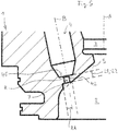
- FIG. 11 shows a sectional illustration of the embodiments from FIG Fig. 1 in a section along the combustion chamber axis A, where as in Fig. 1 on the left side according to the illustration the first exemplary embodiment of a cylinder cover 1 according to the invention is shown, and on the right side according to the illustration the embodiment which is known from the prior art.
- Fig. 3 shows an excerpt from Fig. 2 in an enlarged view to illustrate the definition of various dimensions. In Fig. 3 only the first embodiment of the cylinder cover 1 according to the invention is shown.
- the cylinder cover 1,1 ' comprises a central bore 3, 3' for receiving an outlet valve (not shown) and at least one fuel bore 4, 4 'for receiving a fuel injection nozzle (not shown), with which the fuel, for example heavy oil, in the combustion chamber 2, 2 'can be introduced.
- a plurality of fuel injection nozzles is provided in each cylinder cover 1, 1 ', for example two or three fuel injection nozzles. It goes without saying that a separate fuel bore 4, 4 ′ is then provided for each fuel injection nozzle. Since it is sufficient for understanding, only one fuel bore 4 is referred to in the following, although this naturally also applies to the configuration according to the invention a plurality of fuel bores 4 may be provided, each of which receives a fuel injector.
- Configurations are also possible in which a plurality of bores for receiving a plurality of outlet valves are provided in the cylinder cover for each cylinder.
- each cylinder it is possible for each cylinder to have three or four exhaust valves.
- a bore is then provided in the cylinder cover 1 for each of these exhaust valves, or a larger bore is provided in the cylinder cover, which accommodates a structural unit in which several exhaust valves are contained.
- the cylinder cover 1, 1 ′ furthermore comprises a combustion chamber surface 5, 5 ′ which delimits the combustion chamber 2, 2 ′.
- the combustion chamber surface 5 is designed in the shape of a truncated cone.
- the combustion chamber surface 5 or 5 ' can also have the shape of a spherical surface or a mixed shape of a spherical and a frustoconical surface.
- the central bore 3, 3 'for receiving the exhaust valve extends in the direction of the combustion chamber axis A. Since the combustion chamber surface 5, 5' is a frustoconical surface here, it has a cone axis. In general, the combustion chamber surface has an axis of symmetry.
- This cone axis or axis of symmetry coincides with the combustion chamber axis A and thus with the cylinder axis when the cylinder cover 1 is mounted on a cylinder.
- the fuel bore 4, 4 'for receiving the fuel injection nozzle extends in the direction of a fuel axis B, B' and opens into the combustion chamber surface 5, 5 '.
- a seat surface 41, 41 'for the fuel injection nozzle is provided in the fuel bore 4, 4', on which the fuel injection nozzle rests when it is inserted into the fuel bore 4, 4 '.
- the seat surface 41, 41 ' is arranged perpendicular to the fuel axis B, B'.
- the seat surface 41, 41 ' is connected to the combustion chamber surface 5, 5' via a nozzle channel 42, 42 '.
- the seat surface 41, 41 ' is usually designed in the shape of a truncated cone, which is only indicated in the drawing.
- the seat surface 41, 41 'thus has an axis of symmetry. This coincides with the fuel axis B, B '.
- the fuel axis B, B ' usually forms an angle with the combustion chamber axis A, A' which is different from zero and which, depending on the configuration of the cylinder cover 1 or the space available on the cylinder cover 1, can be up to 45 °.
- the structure and the individual components of the large diesel engine such as the injection system for the liquid mode, the gas supply system for the gas mode, the gas exchange system, the exhaust system or the turbocharger system for the provision of the scavenging or charge air, as well as the monitoring and control system for a large diesel engine are well known to those skilled in the art both for the design as a two-stroke engine and for the design as a four-stroke engine and therefore do not require any further explanation here.
- the monitoring and control system is an electronic system with which all engine or cylinder functions, in particular injection (start and end of injection) and actuation of the exhaust valve, can usually be set or controlled or regulated.
- the nozzle channel 42 has a length ratio which is at most equal to two, the length ratio being defined as the quotient of a maximum length L1 of the nozzle channel 42 and a minimum length L2 of the nozzle channel. These lengths are shown below using Fig. 3 explained in more detail.
- the seat surface 41 Due to the relative arrangement of the fuel bore 4 and the combustion chamber surface 5, it is generally the case that the seat surface 41, whose axis of symmetry is identical to the fuel axis B, is not parallel to the combustion chamber surface 5 lies.
- the nozzle channel 42 which is part of the fuel bore 4, therefore does not open into the combustion chamber surface 5 at a right angle.
- the length of the nozzle channel 42 that is to say its extension in the direction of the fuel axis B, changes when one moves along the circumference of the nozzle channel 42. This is obviously due to the fact that the nozzle channel 42 does not open perpendicularly into the combustion chamber surface 5 or that the seat surface 41 is not parallel to the combustion chamber surface 5.
- the varying length of the nozzle channel 42 represents an essential cause for the formation of cracks in the wall of the combustion chamber 2 and in particular in the combustion chamber surface 5. It is therefore proposed by the invention to reduce these changes in the length of the nozzle channel 42, such that the length ratio, which is the ratio of the maximum length L1 and the minimum length L2 of the nozzle channel 42, is at most two. As a result of this reduction in the change in the length of the nozzle channel 42 seen over its circumference, the formation of cracks in the combustion chamber 2 and in particular in the combustion chamber surface 5 can at least be significantly reduced.
- the ratio of the maximum length L1 and the minimum length L2 should be equal to one, that is, the maximum and the minimum length L1, L2 are identical, so that the nozzle channel 42 has a constant length over its entire circumference . In many applications, however, this ideal case cannot be implemented for practical reasons. In practice, however, it has been shown that there is at least a very good reduction, if not even a complete suppression of crack formation can be realized in particular when the length ratio is at most 1.5 and is preferably less than 1.4.
- a bulge-shaped elevation 6 is provided on the combustion chamber surface 5, which delimits part of the nozzle channel 42, which therefore forms part of the wall of the nozzle channel 42.
- the elevation 6 does not extend around the entire mouth of the nozzle channel 42, but only on the side of the nozzle channel 42 facing the combustion chamber axis A.
- the elevation 6 preferably extends at most around half the circumference of the nozzle channel 42.
- the main function of the elevation 6 is to reduce the variations in the length of the nozzle channel 42. It is therefore preferred that the height H of the elevation 6 changes as seen in the circumferential direction of the nozzle channel 42.
- the height H here means the extension of the elevation 6 perpendicular to the combustion chamber surface 5. In Fig. 3 the height H is drawn where it has its maximum. The height H preferably has its maximum where the nozzle channel 42 would have the minimum of its length without the elevation 6.
- the elevation 6 also has a maximum width B that is at least as large as half the radius R of the cylindrical nozzle channel 42.
- the width B here means the dimension of how far the elevation 6 extends in the combustion chamber surface 5 from the mouth of the nozzle channel 42 extends away.
- the maximum width B is preferably at least as large as the radius R of the nozzle channel 42.
- the elevation can already be used during the manufacture of the cylinder cover 1 be manufactured in one piece with the cylinder cover 1 in a forging or casting process.
- the elevation 6 in a separate work process, for example by means of a welding process such as build-up welding. This last-mentioned measure is particularly advantageous when a cylinder cover 1 that has already been used is to be repaired or serviced.
- a second embodiment of a cylinder cover 1 according to the invention is shown. It shows Fig. 4 a sectional view of the second embodiment in a section along the combustion chamber axis A.
- Fig. 5 shows in the same way as Fig. 3 an enlarged view of a section Fig. 4
- a recess 7 is provided in the combustion chamber surface 5, into which the nozzle channel 42 opens.
- This recess 7 is preferably configured in the shape of a ring segment or ring and is coaxial with the cylindrical nozzle channel 42, the axis of which is the fuel axis B.
- the radius of the recess 7 is denoted by the reference symbol RA.
- the nozzle channel 42 is shortened in those areas along its circumference in which the nozzle channel 42 would be longer without the recess 7 than in other areas.
- the nozzle channel 42 is shortened at least in those areas in which it has the greatest length without the recess 7.
- the aspect ratio is therefore equal to 1.
- the recess 7 is preferably designed in such a way that it reduces the length ratio L1 to L2 to a predeterminable value.
- the minimum value for the aspect ratio is equal to one.
- the length ratio is set to a value greater than one, for example 1.5.
- the respective desired value for the length ratio can then be implemented by the geometric dimensions of the recess 7.
- the recess 7 is primarily intended to reduce or compensate for the difference between the maximum length of the nozzle channel 42 without a recess 7 and the minimum length of the nozzle channel without a recess 7, it is advantageous if the recess 7 is seen in the circumferential direction of the nozzle channel 42, at least extends over half the circumference of the nozzle channel 42. It is also possible that the recess 7, viewed in the circumferential direction of the nozzle channel 42, extends over the entire circumference of the nozzle channel 42. The depth of the recess 7 perpendicular to the combustion chamber surface 5 changes in the circumferential direction of the nozzle channel 7 in order to reduce the difference between the minimum length L2 and the maximum length L1 to the desired value.
- the radius RA of the recess 7 is preferably at least twice as large as the radius R of the nozzle channel 42.
- the recess 7 can already be manufactured in one piece with the cylinder cover 1 in a forging or casting process during the manufacture of the cylinder cover 1.
- the recess 7 can also be produced, after the cylinder cover 1 has been produced, to produce the recess 7 in a separate work process, for example by a cutting process such as milling. This last-mentioned measure is particularly advantageous when a cylinder cover 1 that has already been used is to be repaired or serviced.
- the method according to the invention for repairing a cylinder cover 1 of a cylinder of a large diesel engine is particularly characterized in that the combustion chamber surface 5 of the cylinder cover 1 is machined in such a way that the nozzle channel 42 has an aspect ratio which is at most equal to two, the aspect ratio being the ratio of the maximum Length L1 of the nozzle channel 42 and the minimum length L2 of the nozzle channel.
- the length ratio is preferably changed in that the bead-shaped elevation 6 is applied to the combustion chamber surface 5, for example by means of a welding process, or that the recess is provided in the combustion chamber surface 5, for example by milling.
Landscapes
- Engineering & Computer Science (AREA)
- Mechanical Engineering (AREA)
- Chemical & Material Sciences (AREA)
- Combustion & Propulsion (AREA)
- General Engineering & Computer Science (AREA)
- Cylinder Crankcases Of Internal Combustion Engines (AREA)
- Combustion Methods Of Internal-Combustion Engines (AREA)
- Fuel-Injection Apparatus (AREA)
Priority Applications (4)
| Application Number | Priority Date | Filing Date | Title |
|---|---|---|---|
| EP19180334.5A EP3751123A1 (fr) | 2019-06-14 | 2019-06-14 | Couvercle de cylindre pour un cylindre d'un gros moteur diesel et procédé de réparation d'un couvercle de cylindre |
| CN202010453282.6A CN112081681A (zh) | 2019-06-14 | 2020-05-26 | 用于大型柴油发动机的气缸的气缸盖和维修气缸盖的方法 |
| JP2020093807A JP2020204325A (ja) | 2019-06-14 | 2020-05-29 | 大型ディーゼルエンジンのシリンダ用シリンダカバー及びシリンダカバーの修理方法 |
| KR1020200065061A KR20200143643A (ko) | 2019-06-14 | 2020-05-29 | 대형 디젤 엔진의 실린더를 위한 실린더 커버 및 실린더 커버 수리 방법 |
Applications Claiming Priority (1)
| Application Number | Priority Date | Filing Date | Title |
|---|---|---|---|
| EP19180334.5A EP3751123A1 (fr) | 2019-06-14 | 2019-06-14 | Couvercle de cylindre pour un cylindre d'un gros moteur diesel et procédé de réparation d'un couvercle de cylindre |
Publications (1)
| Publication Number | Publication Date |
|---|---|
| EP3751123A1 true EP3751123A1 (fr) | 2020-12-16 |
Family
ID=66951788
Family Applications (1)
| Application Number | Title | Priority Date | Filing Date |
|---|---|---|---|
| EP19180334.5A Withdrawn EP3751123A1 (fr) | 2019-06-14 | 2019-06-14 | Couvercle de cylindre pour un cylindre d'un gros moteur diesel et procédé de réparation d'un couvercle de cylindre |
Country Status (4)
| Country | Link |
|---|---|
| EP (1) | EP3751123A1 (fr) |
| JP (1) | JP2020204325A (fr) |
| KR (1) | KR20200143643A (fr) |
| CN (1) | CN112081681A (fr) |
Citations (7)
| Publication number | Priority date | Publication date | Assignee | Title |
|---|---|---|---|---|
| JPS5985348U (ja) * | 1982-11-30 | 1984-06-09 | 日産ディーゼル工業株式会社 | 内燃機関のシリンダヘツド |
| EP0226143A2 (fr) * | 1985-12-12 | 1987-06-24 | Cummins Engine Company, Inc. | Culasse résistant à la chaleur |
| EP0297253A1 (fr) * | 1987-07-01 | 1989-01-04 | GebràDer Sulzer Aktiengesellschaft | Agencement de la soupape d'injection de carburant dans un moteur à combustion interne à piston alternatif |
| JPH108970A (ja) * | 1996-06-26 | 1998-01-13 | Nissan Motor Co Ltd | 直接筒内噴射式火花点火機関 |
| JP2005180202A (ja) * | 2003-12-16 | 2005-07-07 | Toyota Motor Corp | 内燃機関 |
| EP2703631A1 (fr) * | 2012-08-31 | 2014-03-05 | Caterpillar Motoren GmbH & Co. KG | Configuration d'injecteur d'une culasse d'un moteur à combustion interne à double carburant |
| DE102015113805A1 (de) * | 2015-08-20 | 2017-02-23 | Dr. Ing. H.C. F. Porsche Aktiengesellschaft | Zylinderkopf für eine Brennkraftmaschine mit Brennstoffeinspritzung |
Family Cites Families (9)
| Publication number | Priority date | Publication date | Assignee | Title |
|---|---|---|---|---|
| GB717215A (en) * | 1951-07-11 | 1954-10-20 | Daimler Benz Ag | Improvements relating to internal combustion engines of the fuel-injection type |
| AT2538U1 (de) * | 1998-01-13 | 1998-12-28 | Avl List Gmbh | Brennkraftmaschine mit zumindest einer einspritzvorrichtung pro zylinder |
| AT3602U1 (de) * | 1999-04-19 | 2000-05-25 | Avl List Gmbh | Zylinderkopf für eine brennkraftmaschine |
| AT3751U1 (de) * | 1999-08-26 | 2000-07-25 | Avl List Gmbh | Brennkraftmaschine mit fremdzündung |
| DE10007659C2 (de) * | 2000-02-19 | 2002-02-07 | Daimler Chrysler Ag | Otto-Brennkraftmaschine |
| CN101761410A (zh) * | 2008-11-10 | 2010-06-30 | 扬动股份有限公司 | 柴油机气缸盖 |
| CN204140219U (zh) * | 2014-09-19 | 2015-02-04 | 顾文元 | 一种气缸盖喷油器安装结构 |
| CN105697180A (zh) * | 2016-04-11 | 2016-06-22 | 广西玉柴机器股份有限公司 | 分层冷却的气缸盖 |
| EP3404235A1 (fr) * | 2017-05-19 | 2018-11-21 | Winterthur Gas & Diesel AG | Gros moteur diesel et procédé de fonctionnement d'un gros moteur diesel |
-
2019
- 2019-06-14 EP EP19180334.5A patent/EP3751123A1/fr not_active Withdrawn
-
2020
- 2020-05-26 CN CN202010453282.6A patent/CN112081681A/zh active Pending
- 2020-05-29 KR KR1020200065061A patent/KR20200143643A/ko active Search and Examination
- 2020-05-29 JP JP2020093807A patent/JP2020204325A/ja active Pending
Patent Citations (7)
| Publication number | Priority date | Publication date | Assignee | Title |
|---|---|---|---|---|
| JPS5985348U (ja) * | 1982-11-30 | 1984-06-09 | 日産ディーゼル工業株式会社 | 内燃機関のシリンダヘツド |
| EP0226143A2 (fr) * | 1985-12-12 | 1987-06-24 | Cummins Engine Company, Inc. | Culasse résistant à la chaleur |
| EP0297253A1 (fr) * | 1987-07-01 | 1989-01-04 | GebràDer Sulzer Aktiengesellschaft | Agencement de la soupape d'injection de carburant dans un moteur à combustion interne à piston alternatif |
| JPH108970A (ja) * | 1996-06-26 | 1998-01-13 | Nissan Motor Co Ltd | 直接筒内噴射式火花点火機関 |
| JP2005180202A (ja) * | 2003-12-16 | 2005-07-07 | Toyota Motor Corp | 内燃機関 |
| EP2703631A1 (fr) * | 2012-08-31 | 2014-03-05 | Caterpillar Motoren GmbH & Co. KG | Configuration d'injecteur d'une culasse d'un moteur à combustion interne à double carburant |
| DE102015113805A1 (de) * | 2015-08-20 | 2017-02-23 | Dr. Ing. H.C. F. Porsche Aktiengesellschaft | Zylinderkopf für eine Brennkraftmaschine mit Brennstoffeinspritzung |
Also Published As
| Publication number | Publication date |
|---|---|
| KR20200143643A (ko) | 2020-12-24 |
| JP2020204325A (ja) | 2020-12-24 |
| CN112081681A (zh) | 2020-12-15 |
Similar Documents
| Publication | Publication Date | Title |
|---|---|---|
| DE4042324C3 (de) | Zylinderkopf für eine Brennkraftmaschine | |
| DE2901211C2 (de) | Verfahren zum Betrieb einer luftverdichtenden, selbstzündenden Brennkraftmaschine und Vorrichtung zur Durchführung des Verfahrens | |
| WO2019068484A1 (fr) | Moteur à combustion interne pour véhicule automobile | |
| EP3872330A1 (fr) | Procédé de fonctionnement d'un grand moteur diesel, ainsi que grand moteur diesel | |
| DE102018000706A1 (de) | Verfahren zum Betreiben einer Verbrennungskraftmaschine für ein Kraftfahrzeug | |
| EP3786498A1 (fr) | Vanne d'arrêt pour une conduite à double paroi, système d'alimentation en gaz et gros moteur | |
| DE10012970B4 (de) | Verfahren zur Bildung eines zündfähigen Kraftstoff-Luftgemischs | |
| EP3951160B1 (fr) | Soupape d'injection de carburant et procédé d'injection de carburant pour un gros moteur diesel, ainsi que gros moteur diesel | |
| EP0900324A1 (fr) | Dispositif d'injection et procede de combustion pour moteurs a combustion interne | |
| EP3896267A1 (fr) | Gros moteur à balayage en équicourant | |
| EP3404235A1 (fr) | Gros moteur diesel et procédé de fonctionnement d'un gros moteur diesel | |
| EP2677141A1 (fr) | Procédé de fonctionnement dýun grand moteur diesel deux temps, ainsi que grand moteur diesel deux temps | |
| DE4033843C2 (de) | Zweistoff-Brennkraftmaschine | |
| EP3751123A1 (fr) | Couvercle de cylindre pour un cylindre d'un gros moteur diesel et procédé de réparation d'un couvercle de cylindre | |
| WO2015086128A1 (fr) | Moteur à étincelles pour un véhicule à moteur et procédé pour faire fonctionner un moteur à étincelles de ce type | |
| DE102006029210A1 (de) | Einspritzdüse zur Einspritzung von Kraftstoff in einen Zylinder einer direkteinspritzenden fremdgezündeten Brennkraftmaschine | |
| EP3564642A1 (fr) | Dispositif de determination de la pression dans un moteur a combustion d'un grand moteur et de grand moteur | |
| CH712921A2 (de) | Längsgespülter Grossmotor. | |
| EP3434874A1 (fr) | Procédé de fonctionnement d'un grand moteur diesel ainsi que grand moteur diesel | |
| DE102014207473B4 (de) | Verfahren zum Betreiben einer Brennkraftmaschine, Injektionseinrichtung für eine Brennkraftmaschine und Brennkraftmaschine | |
| EP3267027A1 (fr) | Tète de buse d'injecteur de gros moteur diesel et son procédé de production | |
| EP4166766A1 (fr) | Grand moteur diesel à balayage axial | |
| DE102018209101A1 (de) | Injektor und Brennkraftmaschine mit adaptivem Einspritzverhalten | |
| EP4019751A1 (fr) | Procédé de fonctionnement d'un grand moteur diesel, ainsi que grand moteur diesel | |
| DE19983702B3 (de) | Verfahren und Vorrichtung zum Einspritzen von Kraftstoff in eine Verbrennungskraftmaschine und Verbrennungskraftmaschine |
Legal Events
| Date | Code | Title | Description |
|---|---|---|---|
| PUAI | Public reference made under article 153(3) epc to a published international application that has entered the european phase |
Free format text: ORIGINAL CODE: 0009012 |
|
| STAA | Information on the status of an ep patent application or granted ep patent |
Free format text: STATUS: THE APPLICATION HAS BEEN PUBLISHED |
|
| AK | Designated contracting states |
Kind code of ref document: A1 Designated state(s): AL AT BE BG CH CY CZ DE DK EE ES FI FR GB GR HR HU IE IS IT LI LT LU LV MC MK MT NL NO PL PT RO RS SE SI SK SM TR |
|
| AX | Request for extension of the european patent |
Extension state: BA ME |
|
| STAA | Information on the status of an ep patent application or granted ep patent |
Free format text: STATUS: THE APPLICATION IS DEEMED TO BE WITHDRAWN |
|
| 18D | Application deemed to be withdrawn |
Effective date: 20210617 |