EP3751105A1 - Co2 recovery system - Google Patents
Co2 recovery system Download PDFInfo
- Publication number
- EP3751105A1 EP3751105A1 EP20179283.5A EP20179283A EP3751105A1 EP 3751105 A1 EP3751105 A1 EP 3751105A1 EP 20179283 A EP20179283 A EP 20179283A EP 3751105 A1 EP3751105 A1 EP 3751105A1
- Authority
- EP
- European Patent Office
- Prior art keywords
- vehicle
- recovery
- air
- recovery device
- switching device
- Prior art date
- Legal status (The legal status is an assumption and is not a legal conclusion. Google has not performed a legal analysis and makes no representation as to the accuracy of the status listed.)
- Granted
Links
- 238000011084 recovery Methods 0.000 title claims abstract description 175
- 239000007789 gas Substances 0.000 claims abstract description 118
- 238000002485 combustion reaction Methods 0.000 claims abstract description 39
- 238000001816 cooling Methods 0.000 claims description 31
- 238000004891 communication Methods 0.000 claims description 19
- 238000011144 upstream manufacturing Methods 0.000 claims description 5
- 230000007423 decrease Effects 0.000 claims description 3
- 239000000112 cooling gas Substances 0.000 claims description 2
- 238000001514 detection method Methods 0.000 claims description 2
- 238000000034 method Methods 0.000 description 16
- 238000010521 absorption reaction Methods 0.000 description 14
- OKKJLVBELUTLKV-UHFFFAOYSA-N Methanol Chemical compound OC OKKJLVBELUTLKV-UHFFFAOYSA-N 0.000 description 12
- 239000000446 fuel Substances 0.000 description 8
- 238000000746 purification Methods 0.000 description 8
- 239000000243 solution Substances 0.000 description 7
- 229910021536 Zeolite Inorganic materials 0.000 description 6
- HNPSIPDUKPIQMN-UHFFFAOYSA-N dioxosilane;oxo(oxoalumanyloxy)alumane Chemical compound O=[Si]=O.O=[Al]O[Al]=O HNPSIPDUKPIQMN-UHFFFAOYSA-N 0.000 description 6
- 239000010457 zeolite Substances 0.000 description 6
- 239000000126 substance Substances 0.000 description 5
- 150000001412 amines Chemical class 0.000 description 4
- 238000010438 heat treatment Methods 0.000 description 4
- 238000005057 refrigeration Methods 0.000 description 4
- 239000007787 solid Substances 0.000 description 4
- 238000001179 sorption measurement Methods 0.000 description 4
- 239000003463 adsorbent Substances 0.000 description 3
- OKTJSMMVPCPJKN-UHFFFAOYSA-N Carbon Chemical compound [C] OKTJSMMVPCPJKN-UHFFFAOYSA-N 0.000 description 2
- 206010041349 Somnolence Diseases 0.000 description 2
- 239000003054 catalyst Substances 0.000 description 2
- 238000004519 manufacturing process Methods 0.000 description 2
- 239000008188 pellet Substances 0.000 description 2
- BWHMMNNQKKPAPP-UHFFFAOYSA-L potassium carbonate Chemical compound [K+].[K+].[O-]C([O-])=O BWHMMNNQKKPAPP-UHFFFAOYSA-L 0.000 description 2
- 239000003507 refrigerant Substances 0.000 description 2
- SECXISVLQFMRJM-UHFFFAOYSA-N N-Methylpyrrolidone Chemical compound CN1CCCC1=O SECXISVLQFMRJM-UHFFFAOYSA-N 0.000 description 1
- 208000032140 Sleepiness Diseases 0.000 description 1
- 239000002250 absorbent Substances 0.000 description 1
- 230000002745 absorbent Effects 0.000 description 1
- 239000007864 aqueous solution Substances 0.000 description 1
- 238000013528 artificial neural network Methods 0.000 description 1
- 238000006243 chemical reaction Methods 0.000 description 1
- 239000002826 coolant Substances 0.000 description 1
- 230000003247 decreasing effect Effects 0.000 description 1
- 230000000694 effects Effects 0.000 description 1
- 230000006870 function Effects 0.000 description 1
- 229930195733 hydrocarbon Natural products 0.000 description 1
- 150000002430 hydrocarbons Chemical class 0.000 description 1
- 229910000027 potassium carbonate Inorganic materials 0.000 description 1
- 238000000926 separation method Methods 0.000 description 1
- 230000037321 sleepiness Effects 0.000 description 1
Images


Classifications
-
- F—MECHANICAL ENGINEERING; LIGHTING; HEATING; WEAPONS; BLASTING
- F01—MACHINES OR ENGINES IN GENERAL; ENGINE PLANTS IN GENERAL; STEAM ENGINES
- F01N—GAS-FLOW SILENCERS OR EXHAUST APPARATUS FOR MACHINES OR ENGINES IN GENERAL; GAS-FLOW SILENCERS OR EXHAUST APPARATUS FOR INTERNAL COMBUSTION ENGINES
- F01N3/00—Exhaust or silencing apparatus having means for purifying, rendering innocuous, or otherwise treating exhaust
- F01N3/08—Exhaust or silencing apparatus having means for purifying, rendering innocuous, or otherwise treating exhaust for rendering innocuous
- F01N3/0807—Exhaust or silencing apparatus having means for purifying, rendering innocuous, or otherwise treating exhaust for rendering innocuous by using absorbents or adsorbents
- F01N3/0828—Exhaust or silencing apparatus having means for purifying, rendering innocuous, or otherwise treating exhaust for rendering innocuous by using absorbents or adsorbents characterised by the absorbed or adsorbed substances
- F01N3/0857—Carbon oxides
-
- F—MECHANICAL ENGINEERING; LIGHTING; HEATING; WEAPONS; BLASTING
- F01—MACHINES OR ENGINES IN GENERAL; ENGINE PLANTS IN GENERAL; STEAM ENGINES
- F01N—GAS-FLOW SILENCERS OR EXHAUST APPARATUS FOR MACHINES OR ENGINES IN GENERAL; GAS-FLOW SILENCERS OR EXHAUST APPARATUS FOR INTERNAL COMBUSTION ENGINES
- F01N3/00—Exhaust or silencing apparatus having means for purifying, rendering innocuous, or otherwise treating exhaust
- F01N3/08—Exhaust or silencing apparatus having means for purifying, rendering innocuous, or otherwise treating exhaust for rendering innocuous
-
- B—PERFORMING OPERATIONS; TRANSPORTING
- B01—PHYSICAL OR CHEMICAL PROCESSES OR APPARATUS IN GENERAL
- B01D—SEPARATION
- B01D53/00—Separation of gases or vapours; Recovering vapours of volatile solvents from gases; Chemical or biological purification of waste gases, e.g. engine exhaust gases, smoke, fumes, flue gases, aerosols
- B01D53/02—Separation of gases or vapours; Recovering vapours of volatile solvents from gases; Chemical or biological purification of waste gases, e.g. engine exhaust gases, smoke, fumes, flue gases, aerosols by adsorption, e.g. preparative gas chromatography
- B01D53/04—Separation of gases or vapours; Recovering vapours of volatile solvents from gases; Chemical or biological purification of waste gases, e.g. engine exhaust gases, smoke, fumes, flue gases, aerosols by adsorption, e.g. preparative gas chromatography with stationary adsorbents
- B01D53/0407—Constructional details of adsorbing systems
-
- B—PERFORMING OPERATIONS; TRANSPORTING
- B01—PHYSICAL OR CHEMICAL PROCESSES OR APPARATUS IN GENERAL
- B01D—SEPARATION
- B01D53/00—Separation of gases or vapours; Recovering vapours of volatile solvents from gases; Chemical or biological purification of waste gases, e.g. engine exhaust gases, smoke, fumes, flue gases, aerosols
- B01D53/02—Separation of gases or vapours; Recovering vapours of volatile solvents from gases; Chemical or biological purification of waste gases, e.g. engine exhaust gases, smoke, fumes, flue gases, aerosols by adsorption, e.g. preparative gas chromatography
- B01D53/04—Separation of gases or vapours; Recovering vapours of volatile solvents from gases; Chemical or biological purification of waste gases, e.g. engine exhaust gases, smoke, fumes, flue gases, aerosols by adsorption, e.g. preparative gas chromatography with stationary adsorbents
- B01D53/0462—Temperature swing adsorption
-
- B—PERFORMING OPERATIONS; TRANSPORTING
- B01—PHYSICAL OR CHEMICAL PROCESSES OR APPARATUS IN GENERAL
- B01D—SEPARATION
- B01D53/00—Separation of gases or vapours; Recovering vapours of volatile solvents from gases; Chemical or biological purification of waste gases, e.g. engine exhaust gases, smoke, fumes, flue gases, aerosols
- B01D53/14—Separation of gases or vapours; Recovering vapours of volatile solvents from gases; Chemical or biological purification of waste gases, e.g. engine exhaust gases, smoke, fumes, flue gases, aerosols by absorption
- B01D53/1456—Removing acid components
- B01D53/1475—Removing carbon dioxide
-
- B—PERFORMING OPERATIONS; TRANSPORTING
- B01—PHYSICAL OR CHEMICAL PROCESSES OR APPARATUS IN GENERAL
- B01D—SEPARATION
- B01D53/00—Separation of gases or vapours; Recovering vapours of volatile solvents from gases; Chemical or biological purification of waste gases, e.g. engine exhaust gases, smoke, fumes, flue gases, aerosols
- B01D53/34—Chemical or biological purification of waste gases
- B01D53/46—Removing components of defined structure
- B01D53/62—Carbon oxides
-
- B—PERFORMING OPERATIONS; TRANSPORTING
- B60—VEHICLES IN GENERAL
- B60H—ARRANGEMENTS OF HEATING, COOLING, VENTILATING OR OTHER AIR-TREATING DEVICES SPECIALLY ADAPTED FOR PASSENGER OR GOODS SPACES OF VEHICLES
- B60H3/00—Other air-treating devices
-
- C—CHEMISTRY; METALLURGY
- C01—INORGANIC CHEMISTRY
- C01B—NON-METALLIC ELEMENTS; COMPOUNDS THEREOF; METALLOIDS OR COMPOUNDS THEREOF NOT COVERED BY SUBCLASS C01C
- C01B32/00—Carbon; Compounds thereof
- C01B32/50—Carbon dioxide
-
- F—MECHANICAL ENGINEERING; LIGHTING; HEATING; WEAPONS; BLASTING
- F01—MACHINES OR ENGINES IN GENERAL; ENGINE PLANTS IN GENERAL; STEAM ENGINES
- F01N—GAS-FLOW SILENCERS OR EXHAUST APPARATUS FOR MACHINES OR ENGINES IN GENERAL; GAS-FLOW SILENCERS OR EXHAUST APPARATUS FOR INTERNAL COMBUSTION ENGINES
- F01N9/00—Electrical control of exhaust gas treating apparatus
-
- G—PHYSICS
- G06—COMPUTING; CALCULATING OR COUNTING
- G06V—IMAGE OR VIDEO RECOGNITION OR UNDERSTANDING
- G06V20/00—Scenes; Scene-specific elements
- G06V20/50—Context or environment of the image
- G06V20/59—Context or environment of the image inside of a vehicle, e.g. relating to seat occupancy, driver state or inner lighting conditions
- G06V20/597—Recognising the driver's state or behaviour, e.g. attention or drowsiness
-
- B—PERFORMING OPERATIONS; TRANSPORTING
- B01—PHYSICAL OR CHEMICAL PROCESSES OR APPARATUS IN GENERAL
- B01D—SEPARATION
- B01D2252/00—Absorbents, i.e. solvents and liquid materials for gas absorption
- B01D2252/20—Organic absorbents
- B01D2252/202—Alcohols or their derivatives
- B01D2252/2021—Methanol
-
- B—PERFORMING OPERATIONS; TRANSPORTING
- B01—PHYSICAL OR CHEMICAL PROCESSES OR APPARATUS IN GENERAL
- B01D—SEPARATION
- B01D2253/00—Adsorbents used in seperation treatment of gases and vapours
- B01D2253/10—Inorganic adsorbents
- B01D2253/106—Silica or silicates
- B01D2253/108—Zeolites
-
- B—PERFORMING OPERATIONS; TRANSPORTING
- B01—PHYSICAL OR CHEMICAL PROCESSES OR APPARATUS IN GENERAL
- B01D—SEPARATION
- B01D2257/00—Components to be removed
- B01D2257/50—Carbon oxides
- B01D2257/504—Carbon dioxide
-
- B—PERFORMING OPERATIONS; TRANSPORTING
- B01—PHYSICAL OR CHEMICAL PROCESSES OR APPARATUS IN GENERAL
- B01D—SEPARATION
- B01D2258/00—Sources of waste gases
- B01D2258/01—Engine exhaust gases
-
- B—PERFORMING OPERATIONS; TRANSPORTING
- B60—VEHICLES IN GENERAL
- B60H—ARRANGEMENTS OF HEATING, COOLING, VENTILATING OR OTHER AIR-TREATING DEVICES SPECIALLY ADAPTED FOR PASSENGER OR GOODS SPACES OF VEHICLES
- B60H3/00—Other air-treating devices
- B60H3/06—Filtering
- B60H2003/0691—Adsorption filters, e.g. activated carbon
-
- F—MECHANICAL ENGINEERING; LIGHTING; HEATING; WEAPONS; BLASTING
- F01—MACHINES OR ENGINES IN GENERAL; ENGINE PLANTS IN GENERAL; STEAM ENGINES
- F01N—GAS-FLOW SILENCERS OR EXHAUST APPARATUS FOR MACHINES OR ENGINES IN GENERAL; GAS-FLOW SILENCERS OR EXHAUST APPARATUS FOR INTERNAL COMBUSTION ENGINES
- F01N2240/00—Combination or association of two or more different exhaust treating devices, or of at least one such device with an auxiliary device, not covered by indexing codes F01N2230/00 or F01N2250/00, one of the devices being
- F01N2240/36—Combination or association of two or more different exhaust treating devices, or of at least one such device with an auxiliary device, not covered by indexing codes F01N2230/00 or F01N2250/00, one of the devices being an exhaust flap
-
- F—MECHANICAL ENGINEERING; LIGHTING; HEATING; WEAPONS; BLASTING
- F01—MACHINES OR ENGINES IN GENERAL; ENGINE PLANTS IN GENERAL; STEAM ENGINES
- F01N—GAS-FLOW SILENCERS OR EXHAUST APPARATUS FOR MACHINES OR ENGINES IN GENERAL; GAS-FLOW SILENCERS OR EXHAUST APPARATUS FOR INTERNAL COMBUSTION ENGINES
- F01N2370/00—Selection of materials for exhaust purification
- F01N2370/22—Selection of materials for exhaust purification used in non-catalytic purification apparatus
- F01N2370/24—Zeolitic material
-
- F—MECHANICAL ENGINEERING; LIGHTING; HEATING; WEAPONS; BLASTING
- F01—MACHINES OR ENGINES IN GENERAL; ENGINE PLANTS IN GENERAL; STEAM ENGINES
- F01N—GAS-FLOW SILENCERS OR EXHAUST APPARATUS FOR MACHINES OR ENGINES IN GENERAL; GAS-FLOW SILENCERS OR EXHAUST APPARATUS FOR INTERNAL COMBUSTION ENGINES
- F01N2370/00—Selection of materials for exhaust purification
- F01N2370/40—Activated carbon or charcoal
-
- F—MECHANICAL ENGINEERING; LIGHTING; HEATING; WEAPONS; BLASTING
- F01—MACHINES OR ENGINES IN GENERAL; ENGINE PLANTS IN GENERAL; STEAM ENGINES
- F01N—GAS-FLOW SILENCERS OR EXHAUST APPARATUS FOR MACHINES OR ENGINES IN GENERAL; GAS-FLOW SILENCERS OR EXHAUST APPARATUS FOR INTERNAL COMBUSTION ENGINES
- F01N2560/00—Exhaust systems with means for detecting or measuring exhaust gas components or characteristics
- F01N2560/02—Exhaust systems with means for detecting or measuring exhaust gas components or characteristics the means being an exhaust gas sensor
- F01N2560/022—Exhaust systems with means for detecting or measuring exhaust gas components or characteristics the means being an exhaust gas sensor for measuring or detecting CO or CO2
-
- F—MECHANICAL ENGINEERING; LIGHTING; HEATING; WEAPONS; BLASTING
- F01—MACHINES OR ENGINES IN GENERAL; ENGINE PLANTS IN GENERAL; STEAM ENGINES
- F01N—GAS-FLOW SILENCERS OR EXHAUST APPARATUS FOR MACHINES OR ENGINES IN GENERAL; GAS-FLOW SILENCERS OR EXHAUST APPARATUS FOR INTERNAL COMBUSTION ENGINES
- F01N2570/00—Exhaust treating apparatus eliminating, absorbing or adsorbing specific elements or compounds
- F01N2570/10—Carbon or carbon oxides
-
- F—MECHANICAL ENGINEERING; LIGHTING; HEATING; WEAPONS; BLASTING
- F01—MACHINES OR ENGINES IN GENERAL; ENGINE PLANTS IN GENERAL; STEAM ENGINES
- F01N—GAS-FLOW SILENCERS OR EXHAUST APPARATUS FOR MACHINES OR ENGINES IN GENERAL; GAS-FLOW SILENCERS OR EXHAUST APPARATUS FOR INTERNAL COMBUSTION ENGINES
- F01N2900/00—Details of electrical control or of the monitoring of the exhaust gas treating apparatus
- F01N2900/06—Parameters used for exhaust control or diagnosing
- F01N2900/12—Parameters used for exhaust control or diagnosing said parameters being related to the vehicle exterior
-
- F—MECHANICAL ENGINEERING; LIGHTING; HEATING; WEAPONS; BLASTING
- F01—MACHINES OR ENGINES IN GENERAL; ENGINE PLANTS IN GENERAL; STEAM ENGINES
- F01N—GAS-FLOW SILENCERS OR EXHAUST APPARATUS FOR MACHINES OR ENGINES IN GENERAL; GAS-FLOW SILENCERS OR EXHAUST APPARATUS FOR INTERNAL COMBUSTION ENGINES
- F01N2900/00—Details of electrical control or of the monitoring of the exhaust gas treating apparatus
- F01N2900/06—Parameters used for exhaust control or diagnosing
- F01N2900/14—Parameters used for exhaust control or diagnosing said parameters being related to the exhaust gas
- F01N2900/1402—Exhaust gas composition
Definitions
- the present disclosure relates to a CO 2 recovery system.
- FIG. 1 is a plan view schematically showing a vehicle 1 having a CO 2 recovery system according to the embodiment.
- FIG. 2 is a side view schematically showing a vehicle 1 having this CO 2 recovery system.
- the physical absorption method is a method of making an absorption solution, which is able to dissolve the CO 2 (for example methanol or N-methyl pyrrolidone), contact the gas containing CO 2 to physically make the CO 2 be absorbed at a high pressure and low temperature, and heating (or reducing the pressure) the absorption solution to recover the CO 2 from it.
- CO 2 for example methanol or N-methyl pyrrolidone
- the CO 2 recovery device 21 the physical adsorption method is employed as the method of recovery of the CO 2 in the exhaust. Therefore, the CO 2 recovery device 21 is configured as a container holding pellet shaped zeolite.
- the flow path switching device 22 is a device switching the type of the gas flowing into the CO 2 recovery device 21.
- the flow path switching device 22 is arranged in or below luggage space positioned at the back of the vehicle 1.
- the flow path switching device 22 communicates through an inside connection passage 34 with the inside of the vehicle 1.
- the inside connection passage 34 extends from the flow path switching device 22 toward the front of the vehicle 1 in the front-back direction of the vehicle 1.
- the inlet of the inside connection passage 34 is arranged near a back seat of the vehicle 1 at the inside of the vehicle 1. Therefore, the inside connection passage 34 is configured so that it is possible to make the air at the inside of the vehicle 1 flow from inside of the vehicle 1 to the flow path switching device 22.
- the inside connection passage 34 may be configured in any way. Therefore, for example, the inlet of the inside connection passage 34 may be arranged at the front of the inside of the vehicle 1.
- the cooling device 24 does not necessarily have to be configured as a refrigeration circuit.
- the cooling device 24 may be configured in any way so long as cooling the exhaust gas flowing through the exhaust pipe connection passage 32. Therefore, for example, the cooling device 24 has a radiator of the vehicle 1 and is configured to cool the exhaust gas flowing through the exhaust pipe connection passage 32 by the coolant cooled at the radiator.
- the flow path switching device 22 when the flow path switching device 22 is set so that the communication path 31 communicates with the inside connection passage 34 and the suction pump 23 is operating, the air at the inside of the vehicle 1 is supplied to the CO 2 recovery device 21.
- step S31 the degree of awakeness of the driver is calculated at the ECU 40 based on the output of the driver monitor camera 46, etc.
- step S32 it is judged if the degree of awakeness detected at step S31 is lower than a predetermined reference value, that is, if the concentration of the driver is falling. If, at step S32, it is judged that the degree of awakeness of the driver is lower than the reference value, the control routine proceeds to step S33.
Abstract
Description
- The present disclosure relates to a CO2 recovery system.
- Known in the past has been a CO2 recovery system used for a vehicle having a CO2 recovery device recovering CO2 contained in inflowing exhaust gas (for example, PTL 1). In particular, in the CO2 recovery system described in
PTL 1, the exhaust gas discharged from an internal combustion engine mounted in a vehicle is supplied to the CO2 recovery device, and as a result the CO2 in the exhaust gas is recovered by the CO2 recovery device. - [PTL 1]
JP 2014-504695 A - CO2 is contained not only in the exhaust gas, but also in the air at the outside of a vehicle or the air at the inside of a vehicle. Therefore, it may also be considered to recover the CO2 in the air at the inside of and outside of a vehicle. However, in the CO2 recovery system described in
PTL 1, nothing other than the exhaust gas of the internal combustion engine was supplied to the CO2 recovery device. Accordingly, it was not possible to recover CO2 from the air at the inside of and outside of the vehicle. - In view of the above technical problem, an object of the present disclosure is to provide a CO2 recovery system able to recover CO2 in gases present in a plurality of different regions of the vehicle.
- The present invention has as its gist the following.
- (1) A CO2 recovery system used in a vehicle, comprising:
- a CO2 recovery device recovering CO2 contained in inflowing gas; and
- a flow rate control device controlling flow rates of gases present in a plurality of different regions of the vehicle flowing into the CO2 recovery device,
- wherein the gases present at the plurality of different regions include at least any two among air at an outside of the vehicle, air at an inside of the vehicle, and exhaust gas discharged from a body of an internal combustion engine of the vehicle.
- (2) The CO2 recovery system according to above (1), wherein the flow rate control device controls the flow rate of air at the outside of the vehicle flowing into the CO2 recovery device, based on a CO2 concentration in the air at the outside of the vehicle.
- (3) The CO2 recovery system according to above (1) or (2), wherein the flow rate control device controls the flow rate of air at the inside of the vehicle flowing into the CO2 recovery device, based on a CO2 concentration in the air at the inside of the vehicle.
- (4) The CO2 recovery system according to any one of above (1) to (3), wherein
- the flow rate control device has a switching device arranged at an upstream side of the CO2 recovery device in a direction of flow of the gas and a pump forcibly sending gases from a plurality of different regions through the switching device to the CO2 recovery device, and
- the switching device switches the gas to be flowed to the CO2 recovery device among the gases present in the plurality of different regions.
- (5) The CO2 recovery system according to above (4), wherein
- the vehicle has an internal combustion engine having the body of the internal combustion engine and an exhaust passage through which exhaust gas discharged from the body of the internal combustion engine flows,
- the gases present at the plurality of different regions include exhaust gas discharged from the body of the internal combustion engine, and
- the switching device communicates with the exhaust passage so that exhaust gas can flow to the switching device from the exhaust passage.
- (6) The CO2 recovery system according to above (5), wherein
- a first connection passage communicating the exhaust passage with the switching device is provided with a cooling device cooling the gas, and
- a second connection passage communicating an outside of the vehicle with the switching device and a third connection passage communicating an inside of the vehicle with the switching device are not provided with cooling devices.
- (7) The CO2 recovery system according to above (5), wherein a communication path communicating the switching device with the CO2 recovery device is provided with a cooling device cooling gas flowing through the communication path.
- (8) The CO2 recovery system according to any one of above (5) to (7), wherein the flow rate control device controls the flow rate of the exhaust gas, which is discharged from the body of the internal combustion engine, flowing into the CO2 recovery device, based on the CO2 concentration in the exhaust gas flowing through the exhaust passage.
- (9) The CO2 recovery system according to any one of above (5) to (8), wherein the flow rate control device is controlled so that when the internal combustion engine is stopped, at least one of air at the outside of the vehicle and air at the inside of the vehicle, flows into the CO2 recovery device.
- (10) The CO2 recovery system according to any one of above (4) to (9), wherein when the flow rate control device is controlled so that air at the outside of the vehicle flows into the CO2 recovery device, the pump is controlled so that an output of the pump decreases, as the a running speed of the vehicle becomes faster.
- (11) The CO2 recovery system according to any one of above (1) to (10), wherein
- the system further comprises an awakeness degree detection device for detecting a degree of awakeness of a driver,
- the CO2 recovery device is configured to be able to return gas discharged from the CO2 recovery device to the inside of the vehicle, and
- when a degree of awakeness of the driver is lower than a predetermined threshold value, the flow rate control device is controlled so that the air at the inside of the vehicle flows into the CO2 recovery device and the gas discharged from the CO2 recovery device is returned to the inside of the vehicle.
- According to the present disclosure, there is provided a CO2 recovery system able to recover CO2 in gases present in a plurality of different regions of the vehicle.
-
-
FIG. 1 is a plan view schematically showing a vehicle having a CO2 recovery system according to one embodiment. -
FIG. 2 is a side view schematically showing a vehicle having a CO2 recovery system according to one embodiment. -
FIG. 3 is a view schematically explaining the configuration of a CO2 recovery system. -
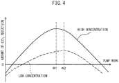
FIG. 4 is a view showing a relationship between pump work performed by a suction pump and an amount of CO2 reduction. -
FIG. 5 is a flow chart showing a control routine in control in the CO2 recovery system. -
FIG. 6 is a view schematically explaining the configuration of a CO2 recovery system according to a second embodiment. -
FIG. 7 is a flow chart showing a control routine in control in the CO2 recovery system. - Below, referring to the drawings, an embodiment will be explained in detail. Note that, in the following explanation, similar component elements are assigned the same reference signs.
- Referring to
FIGS. 1 and2 , a vehicle mounting a CO2 recovery system according to one embodiment will be explained.FIG. 1 is a plan view schematically showing avehicle 1 having a CO2 recovery system according to the embodiment.FIG. 2 is a side view schematically showing avehicle 1 having this CO2 recovery system. - As shown in
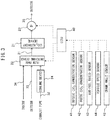
FIGS. 1 and2 , thevehicle 1 has aninternal combustion engine 10 for driving thevehicle 1 and a CO2 recovery system 20 for recovering CO2. Note that, in the present embodiment, theinternal combustion engine 10 is used as the power source for driving thevehicle 1, but an electric motor may be used as the power source for driving thevehicle 1 in addition to theinternal combustion engine 10 or instead of theinternal combustion engine 10. - The
internal combustion engine 10 has anengine body 11,exhaust pipe 12,exhaust purification device 13, andmuffler 14. Theengine body 11 is arranged in an engine compartment formed at the front of the vehicle 1 (left side ofFIGS. 1 and2 ). Theexhaust pipe 12 mainly extends under anunderbody 2 of thevehicle 1 from theengine body 11 toward the back of thevehicle 1 in the front-back direction of thevehicle 1. Theexhaust purification device 13 andmuffler 14 are provided at theexhaust pipe 12. - The
engine body 11 generates power for driving thevehicle 1 by burning fuel at the inside. The exhaust gas generated due to combustion of fuel in theengine body 11 flows into theexhaust pipe 12. - The
exhaust pipe 12 is connected through anexhaust manifold 15 to theengine body 11. The exhaust gas discharged from theengine body 11 flows through the inside of theexhaust pipe 12. From the outlet of theexhaust pipe 12, exhaust gas is released to the atmosphere. Theexhaust pipe 12 forms an exhaust passage through which exhaust gas discharged from theengine body 11 flows. - The
exhaust purification device 13 purifies the NOX, HC (hydrocarbons), CO, particulate, and other substances in the exhaust gas flowing into theexhaust purification device 13. Theexhaust purification device 13 is, for example, a three-way catalyst, a NOX storage reduction catalyst, or a particulate filter. Note that, a plurality ofexhaust purification devices 13 may also be provided at theexhaust pipe 12. - The
muffler 14 causes the temperature and pressure of the exhaust gas flowing through theexhaust pipe 12 to decrease, to reduce the exhaust noise. Themuffler 14 is arranged at the downstream side of theexhaust purification device 13 in the downstream direction of the exhaust gas. Note that, a plurality of themufflers 14 may also be provided at theexhaust pipe 12. - The CO2 recovery system 20 has a CO2 recovery device 21, flow
path switching device 22,suction pump 23, and coolingdevice 24. - The CO2 recovery device 21 is a device for recovering the CO2 in the gas supplied to the CO2 recovery device 21. In the present embodiment, the CO2 recovery device is arranged in or below luggage space positioned at the back of the
vehicle 1. Note that, the CO2 recovery device 21 is a heavy object, therefore it is preferable to arrange it as low as possible in the vertical direction in the luggage space. - The method of recovery of CO2 in the gas by the CO2 recovery device 21 may be, for example, the physical adsorption method, physical absorption method, chemical absorption method, cryogenic separation method, etc.
- The physical adsorption method, for example, is a method of bringing activated carbon, zeolite, or other solid adsorbent into contact with a gas containing CO2 to thereby make the CO2 be adsorbed at the solid adsorbent, and heating (or reducing the pressure) to thereby make the CO2 be desorbed from the solid adsorbent.
- When employing the physical adsorption method, the CO2 recovery device 21 is, for example, configured as a container holding pellet shaped zeolite. By making the gas containing CO2 flow through the container, the CO2 is adsorbed by the zeolite.
- The physical absorption method is a method of making an absorption solution, which is able to dissolve the CO2 (for example methanol or N-methyl pyrrolidone), contact the gas containing CO2 to physically make the CO2 be absorbed at a high pressure and low temperature, and heating (or reducing the pressure) the absorption solution to recover the CO2 from it.
- When employing the physical absorption method, the CO2 recovery device 21 is, for example, configured as a container containing methanol. By making the gas containing CO2 flow through the methanol held in the container, the CO2 is absorbed by the methanol.
- The chemical absorption method is a method of making an absorption solution, which is able to selectively dissolve the CO2 (for example, amine or a potassium carbonate aqueous solution), contact the gas containing CO2 to make the CO2 be absorbed in the absorption solution by a chemical reaction, and heating it thereby making the CO2 be desorbed from the absorption solution.
- When employing the chemical absorption method, the CO2 recovery device 21 is, for example, configured as a container holding amine. By making the gas containing CO2 flow through the inside of the amine held in the container, the CO2 is absorbed by the amine.
- In the present embodiment, in the CO2 recovery device 21, the physical adsorption method is employed as the method of recovery of the CO2 in the exhaust. Therefore, the CO2 recovery device 21 is configured as a container holding pellet shaped zeolite.
- The flow
path switching device 22 is a device switching the type of the gas flowing into the CO2 recovery device 21. In the present embodiment, the flowpath switching device 22 is arranged in or below luggage space positioned at the back of thevehicle 1. - The flow
path switching device 22 communicates through acommunication path 31 with the CO2 recovery device 21. Therefore, the gas flowing out from the flowpath switching device 22 flows through thecommunication path 31 into the CO2 recovery device 21. In other words, the flowpath switching device 22 is arranged at the upstream side of the CO2 recovery device 21 in the direction of flow of gas. - Further, the flow
path switching device 22 communicates through an exhaustpipe connection passage 32 with theexhaust pipe 12. In particular, the exhaustpipe connection passage 32 communicates with theexhaust pipe 12 at the downstream side from themuffler 14 in the direction of flow of exhaust gas. Therefore, the exhaustpipe connection passage 32 is configured so that exhaust gas can flow from theexhaust pipe 12 to the flowpath switching device 22. In particular, since the exhaustpipe connection passage 32 communicates with theexhaust pipe 12 at the downstream side from themuffler 14, relatively low temperature exhaust gas flows into the exhaustpipe connection passage 32. Note that, in the present embodiment, the exhaustpipe connection passage 32 communicates with theexhaust pipe 12 at the downstream side from themuffler 14, but it may communicate with it upstream from themuffler 14 and may also communicate with it upstream from theexhaust purification device 13. - In addition, the flow
path switching device 22 communicates through anoutside connection passage 33 with the outside of thevehicle 1. In the present embodiment, theoutside connection passage 33 extends below theunderbody 2 of thevehicle 1 from the flowpath switching device 22 to the front of thevehicle 1 in the front-back direction of thevehicle 1. In particular, in the present embodiment, the inlet of theoutside connection passage 33 is arranged in the engine compartment. Therefore, theoutside connection passage 33 is configured to enable the outside air around thevehicle 1 to flow from outside of thevehicle 1 to the flowpath switching device 22. Note that, if able to make the air at the outside of thevehicle 1 flow through theoutside connection passage 33 to the flowpath switching device 22, theoutside connection passage 33 may be configured in any way. Therefore, for example, the inlet of theoutside connection passage 33 may be arranged at a lateral surface of the vehicle 1 (surface extending in front-back direction of vehicle 1). - Furthermore, the flow
path switching device 22 communicates through aninside connection passage 34 with the inside of thevehicle 1. In the present embodiment, theinside connection passage 34 extends from the flowpath switching device 22 toward the front of thevehicle 1 in the front-back direction of thevehicle 1. In particular, in the present embodiment, the inlet of theinside connection passage 34 is arranged near a back seat of thevehicle 1 at the inside of thevehicle 1. Therefore, theinside connection passage 34 is configured so that it is possible to make the air at the inside of thevehicle 1 flow from inside of thevehicle 1 to the flowpath switching device 22. Note that, if able to make the air at the inside of thevehicle 1 flow through theinside connection passage 34 to the flowpath switching device 22, theinside connection passage 34 may be configured in any way. Therefore, for example, the inlet of theinside connection passage 34 may be arranged at the front of the inside of thevehicle 1. - The flow
path switching device 22 is configured to switch the passage communicating with thecommunication path 31 among the exhaustpipe connection passage 32, outsideconnection passage 33, and insideconnection passage 34. Therefore, the flowpath switching device 22 is configured to switch the gas to be flowed into the CO2 recovery device 21 among the exhaust gas discharged from theengine body 11, the air at the outside of thevehicle 1, and the air at the inside of thevehicle 1. Specifically, the flowpath switching device 22 is, for example, a four-way valve. In the present embodiment, the flowpath switching device 22 makes one passage among the exhaustpipe connection passage 32, outsideconnection passage 33, and insideconnection passage 34 selectively communicate with thecommunication path 31. Therefore, in the present embodiment, the flowpath switching device 22 makes one of the exhaust gas discharged from theengine body 11, the air at the outside of thevehicle 1, and the air at the inside of thevehicle 1, selectively flow into the CO2 recovery device 21. - Note that, in the present embodiment, the flow
path switching device 22 is communicated with the exhaustpipe connection passage 32, outsideconnection passage 33, and insideconnection passage 34. However, the flowpath switching device 22 may also be configured to communicate with any two of these passages. Therefore, the flow path switching device is configured so as to switch the gas to be flowed into the CO2 recovery device 21 between two gases among the exhaust gas discharged from theengine body 11, the air at the outside of thevehicle 1, and the air at the inside of thevehicle 1. - Further, in the present embodiment, the flow
path switching device 22 is configured so that one passage among the exhaustpipe connection passage 32, outsideconnection passage 33, and insideconnection passage 34 is made to selectively communicate with thecommunication path 31. However, the flowpath switching device 22 may also be configured to change the ratio of the flow rate of gases flowing from a plurality ofpassages communication path 31. In this case, the flowpath switching device 22 is configured as solenoid adjustment valves changing in opening area, which are provided at thepassages - The
suction pump 23 is provided at theexhaust passage 35 communicated with the CO2 recovery device 21. Theexhaust passage 35 is configured so as to discharge gas after recovery of CO2 at the CO2 recovery device 21 into the atmosphere. - The
suction pump 23 is configured so as to suck in gas from the CO2 recovery device 21. In other words, thesuction pump 23 is configured so as to forcibly send gas from theexhaust pipe 12, inside of thevehicle 1, and outside of thevehicle 1, through the flowpath switching device 22 to the CO2 recovery device 21. Further, thesuction pump 23 is configured so as to be able to change the output. If the output of thesuction pump 23 becomes larger, the flow rate of the gas flowing through the CO2 recovery device 21 becomes greater. - In the present embodiment, the flow
path switching device 22 andsuction pump 23 function as a flow rate control device controlling the flow rates of gases present in a plurality of different regions of the vehicle 1 (for example, at least any two of air at the outside of thevehicle 1, air at the inside of thevehicle 1, and exhaust gas discharged from the engine body 11) into the CO2 recovery device 21. - The
cooling device 24 is provided in the exhaustpipe connection passage 32 and cools the exhaust gas flowing through the exhaustpipe connection passage 32. Further, thecooling device 24 is not provided at theoutside connection passage 33 and insideconnection passage 34. - The
cooling device 24 is, for example, configured as a refrigeration circuit having a compressor, condenser, expansion valve, and evaporator. In thecooling device 24, a refrigeration cycle is realized by a refrigerant circulating through these component parts. In particular, the evaporator performs heat exchange with the exhaust gas flowing through the exhaustpipe connection passage 32 either directly or indirectly through a medium so as to cool this exhaust gas. The temperature of the refrigerant at the refrigeration circuit falls to a temperature lower than the temperature of the atmosphere, therefore in the present embodiment, thecooling device 24 can make the temperature of the exhaust gas flowing into the CO2 recovery device 21 fall to a temperature lower than the temperature of the atmosphere (ordinary temperature). - Note that, the
cooling device 24 does not necessarily have to be configured as a refrigeration circuit. Thecooling device 24 may be configured in any way so long as cooling the exhaust gas flowing through the exhaustpipe connection passage 32. Therefore, for example, thecooling device 24 has a radiator of thevehicle 1 and is configured to cool the exhaust gas flowing through the exhaustpipe connection passage 32 by the coolant cooled at the radiator. - Further, in the present embodiment, the
cooling device 24 is provided at the exhaustpipe connection passage 32. However, thecooling device 24 may be provided at thecommunication path 31. In this case, thecooling device 24 can cool not only just the exhaust gas flowing through the exhaustpipe connection passage 32, but also all of the gases flowing into the CO2 recovery device 21. Further, thecooling device 24 may be arranged around the CO2 recovery device 21 and configured to cool the CO2 recovery device 21. -
FIG. 3 is a view schematically explaining the configuration of the CO2 recovery system 20. As shown inFIG. 3 , the CO2 recovery system 20 has anECU 40. TheECU 40 has a processor for performing various processing, a memory storing a program and various information, and an interface connected to various actuators and various sensors. - Further, the CO2 recovery system 20 has various sensors. Specifically, the CO2 recovery system 20 has an outside CO2 concentration sensor 41, inside CO2 concentration sensor 42, air-
fuel ratio sensor 43,vehicle speed sensor 44, and crankangle sensor 45. - The outside CO2 concentration sensor 41 is provided at the outside of the
vehicle 1 and detects the concentration of CO2 in the air (atmosphere) at the outside of the surroundings of thevehicle 1. The inside CO2 concentration sensor 42 is provided at the inside of thevehicle 1 and detects the concentration of CO2 in the air at the inside. The air-fuel ratio sensor 43 is provided at theexhaust pipe 12 and detects the air-fuel ratio of the exhaust gas flowing through theexhaust pipe 12. Thevehicle speed sensor 44 is provided around an axle of thevehicle 1 and detects the speed of thevehicle 1 based on the rotational speed of the axle. Thecrank angle sensor 45 detects the rotational angle of the crankshaft of theinternal combustion engine 10. - Further, the
ECU 40 is connected to various actuators of the CO2 recovery system 20 and controls these actuators. Specifically, theECU 40 is connected to the flowpath switching device 22,suction pump 23, and coolingdevice 24 and controls them. - In the CO2 recovery system 20 configured as above, when the flow
path switching device 22 is set so that thecommunication path 31 communicates with theinside connection passage 34 and thesuction pump 23 is operating, the air at the inside of thevehicle 1 is supplied to the CO2 recovery device 21. - On the other hand, when the flow
path switching device 22 is set so that thecommunication path 31 communicates with theoutside connection passage 33 and thesuction pump 23 is operating, the air at the outside of thevehicle 1 is supplied to the CO2 recovery device. Note that, when the flowpath switching device 22 is set in this way, even if thesuction pump 23 is not being operated, if thevehicle 1 is running, air at the outside of thevehicle 1 is supplied to the CO2 recovery device 21. - Furthermore, when the flow
path switching device 22 is set so that thecommunication path 31 communicates with the exhaustpipe connection passage 32 and thesuction pump 23 is operating, the exhaust gas flowing through theexhaust pipe 12 is supplied to the CO2 recovery device 21. Note that, when the flowpath switching device 22 is set in this way, even if thesuction pump 23 is not operating, only a small amount of exhaust gas is supplied to the CO2 recovery device 21. - Further, if the exhaust gas flowing through the
exhaust pipe 12 is high in temperature, the exhaust gas is cooled by the coolingdevice 24 before flowing into the CO2 recovery device 21, by the coolingdevice 24 being operated. For this reason, low temperature exhaust gas is made to flow to the CO2 recovery device 21. - Next, referring to
FIGS. 4 and5 , control at the CO2 recovery system 20 will be explained. - The concentration of CO2 contained in the exhaust gas discharged from the
engine body 11 is usually far higher than the concentration of CO2 in the air at the inside of thevehicle 1 and outside of the vehicle 1 (atmosphere). Further, the amount of recovery of CO2 at the CO2 recovery device 21 per unit gas flow rate becomes greater, as the concentration of CO2 in the gas becomes higher. - Therefore, in the present embodiment, while the
internal combustion engine 10 is operating, the flowpath switching device 22 is set to the exhaust pipe connection position making thecommunication path 31 communicate with the exhaustpipe connection passage 32. As a result, while theinternal combustion engine 10 is operating, the exhaust gas flows through the exhaustpipe connection passage 32 to the CO2 recovery device 21. - Further, the exhaust gas flowing through the
exhaust pipe 12 is high in temperature. As explained above, if zeolite becomes high in temperature, it makes the adsorbed CO2 be desorbed. Therefore, if high temperature exhaust gas flows as is to the CO2 recovery device 21, the CO2 recovery device 21 becomes high in temperature and the recovered CO2 is desorbed from the CO2 recovery device 21. - Such a situation can occur even when a solid absorbent other than zeolite or another method is used for recovering the CO2. For example, even when using the physical absorption method or the chemical absorption method, the CO2 is separated from the absorption solution by heating as explained above. Therefore, in such a case as well, if high temperature exhaust gas flows into the CO2 recovery device 21, the recovered CO2 is desorbed from the CO2 recovery device 21.
- Therefore, in the present embodiment, when making exhaust gas flow through the exhaust
pipe connection passage 32 into the CO2 recovery device 21, thecooling device 24 is made to operate. Due to this, exhaust gas is cooled before flowing into the CO2 recovery device 21. Accordingly, the CO2 recovery device 21 is kept from becoming high in temperature and accordingly the recovered CO2 is kept from being desorbed from the CO2 recovery device 21. - On the other hand, while the
internal combustion engine 10 is stopped, no exhaust gas is discharged from theengine body 11. Therefore, there is no need to supply gas in theexhaust pipe 12 to the CO2 recovery device 21. Therefore, in the present embodiment, while theinternal combustion engine 10 is stopped, the flowpath switching device 22 is set to either of the outside connection position making thecommunication path 31 communicate with theoutside connection passage 33 or of the inside connection position making thecommunication path 31 communicate with theinside connection passage 34. - Note that, if the flow
path switching device 22 is configured so as to be able to connect thecommunication path 31 to a plurality of passages, while theinternal combustion engine 10 is stopped, thecommunication path 31 may be communicated with both of theoutside connection passage 33 and insideconnection passage 34. Therefore, the flowpath switching device 22 is controlled so that while theinternal combustion engine 10 is stopped, at least one of the air at the outside of thevehicle 1 and the air at the inside of thevehicle 1 flows into the CO2 recovery device 21. - In particular, in the present embodiment, while the
internal combustion engine 10 is stopped, the flowpath switching device 22 is controlled so that the air with the higher CO2 concentration among the air at the outside and the air at the inside, is supplied to the CO2 recovery device 21. Therefore, when the CO2 concentration in the air at the outside is high, the flowpath switching device 22 is set to the outside connection position, while when the CO2 concentration in the air at the inside is high, the flowpath switching device 22 is set to the inside connection position. As a result, the CO2 recovery device 21 is supplied with air with a high CO2 concentration, and accordingly the recovery efficiency of the CO2 can be raised. On the other hand, when theinternal combustion engine 10 is stopped and the CO2 concentration in the air at the outside and the CO2 concentration in the air at the inside are substantially equal, the flowpath switching device 22 is set to the outside connection position. - Next, referring to
FIG. 4 , control of the output of thesuction pump 23 will be explained.FIG. 4 is a view showing a relationship between pump work performed by asuction pump 23 and an amount of CO2 reduction. The amount of CO2 reduction shows the amount of CO2 recovered by the CO2 recovery device 21 per unit time minus the amount of CO2 corresponding to the energy required for driving the pump. Therefore, it can be said that the larger the amount of CO2 reduction, the more efficiently CO2 is recovered at the CO2 recovery device 21. The solid line in the figure shows the relationship when the CO2 concentration in the gas supplied to the CO2 recovery device 21 is high, while the broken line in the figure shows the relationship when this CO2 concentration is low. - As shown in
FIG. 4 , when the pump work of thesuction pump 23 is small, the flow rate of gas flowing into the CO2 recovery device 21 is small, therefore the amount of CO2 recovery at the CO2 recovery device 21 is small. As a result, in a region with a small pump work, the amount of CO2 reduction is small. On the other hand, when the pump work of thesuction pump 23 is large, the flow resistance at the CO2 recovery device 21 is large and the flow rate of gas flowing through the CO2 recovery device 21 is small with respect to the magnitude of the pump work. As a result, even in a region with large pump work, the amount of CO2 reduction is small. On the other hand, in a region with an intermediate extent of the magnitude of the pump work, the flow rate of the gas flowing into the CO2 recovery device 21 is large and the flow resistance is small, therefore the amount of CO2 reduction is great. - In this regard, the magnitude of the pump work where the amount of CO2 reduction is maximum, changes according to the CO2 concentration in the gas. In the illustrated example, when the CO2 concentration is high, the amount of CO2 reduction is maximum when the pump work is W1. On the other hand, when the CO2 concentration is low, the amount of CO2 reduction is maximum when the pump work is W2.
- Therefore, in the present embodiment, the output of the
suction pump 23 is set based on the CO2 concentration in the gas supplied to the CO2 recovery device 21. Specifically, if there is the relationship such as shown inFIG. 4 , when the CO2 concentration is relatively high, the output of thesuction pump 23 is controlled so that the pump work is relatively low. By controlling thesuction pump 23 in this way, it is possible to efficiently recover the CO2 at the CO2 recovery device 21. - Further, in the present embodiment, when the flow
path switching device 22 is set to the outside connection position, thesuction pump 23 is controlled so that its output becomes lower as the running speed of thevehicle 1 becomes faster. - In this regard, as explained above, when the flow
path switching device 22 is set to the outside connection position, if thevehicle 1 is running, outside air is forcibly made to flow to theoutside connection passage 33. Therefore, even if the output of thesuction pump 23 is made smaller, a large amount of air can be supplied to the CO2 recovery device 21. Therefore, it is possible to reduce the pump work at thesuction pump 23 while maintaining the amount of recovery of CO2 at the CO2 recovery device 21. -
FIG. 5 is a flow chart showing a control routine in control in the CO2 recovery system 20. The illustrated control routine is performed every certain time interval. - First, at step S11, the operating state of the internal combustion engine and the CO2 concentrations in the gases at a plurality of different regions of the
vehicle 1 are detected, based on the outputs of various sensors. Next, at step S12, it is judged if theinternal combustion engine 10 is being operated. For example, if the current engine rotational speed calculated based on the output of thecrank angle sensor 45 is zero, it is judged that theinternal combustion engine 10 has stopped. When it is not zero, it is judged that theinternal combustion engine 10 is being operated. At step S12, if it is judged that theinternal combustion engine 10 is being operated, the control routine proceeds to step S13. - At step S13, the flow
path switching device 22 is set to the exhaust pipe connection position. Next, at step S14, the output of thesuction pump 23 is set based on the CO2 concentration in the gas flowing through the exhaustpipe connection passage 32 to the CO2 recovery device 21. The CO2 concentration is calculated based on the output of the air-fuel ratio sensor 43. As the air-fuel ratio of the air-fuel ratio sensor 43 is larger (leaner), the calculated CO2 concentration is smaller. Next, at step S15, thecooling device 24 is operated and the temperature of the exhaust gas flowing into the flowpath switching device 22 is lowered. - On the other hand, if, at step S12, it is judged that the
internal combustion engine 10 is not operating, the control routine proceeds to step S16. At step S16, it is judged if the CO2 concentration at the inside of thevehicle 1 is higher than the CO2 concentration at the outside of thevehicle 1. The CO2 concentration at the inside of thevehicle 1 is detected by the inside CO2 concentration sensor 42, while the CO2 concentration at the outside of thevehicle 1 is detected by the outside CO2 concentration sensor 41. - If, at step S16, it is judged that the CO2 concentration at the inside of the
vehicle 1 is higher than the CO2 concentration at the outside of thevehicle 1, the control routine proceeds to step S17. At step S17, the flowpath switching device 22 is set to the inside connection position. Next, at step S18, the output of thesuction pump 23 is set based on the CO2 concentration at the inside of thevehicle 1. Accordingly, the flow rate of air at the inside of thevehicle 1 flowing into the CO2 recovery device 21 is controlled based on the CO2 concentration at the inside of thevehicle 1. Next, at step S19, thecooling device 24 is stopped. - On the other hand, if, at step S16, it is judged that the CO2 concentration at the inside of the
vehicle 1 is equal to or greater than the CO2 concentration of the outside of thevehicle 1, the control routine proceeds to step S20. At step S20, the flowpath switching device 22 is set to the outside connection position. Next, at step S21, the output of thesuction pump 23 is set based on the CO2 concentration at the outside of thevehicle 1 and the speed of thevehicle 1. Accordingly, the flow rate of the air at the outside of thevehicle 1 flowing into the CO2 recovery device 21 is controlled, based on the CO2 concentration at the outside of thevehicle 1 and the speed of thevehicle 1. The speed of thevehicle 1 is detected by thevehicle speed sensor 44. Next, at step S22, thecooling device 24 is stopped. - Next, referring to
FIG. 6 , the CO2 recovery system according to a second embodiment will be explained. The configuration and control of the CO2 recovery system according to the second embodiment are basically similar to the configuration and control of the CO2 recovery system according to the first embodiment. Below, the parts different from the first embodiment will be focused on in the explanation. -
FIG. 6 is a view schematically explaining the configuration of a CO2 recovery system 20 according to the second embodiment. As shown inFIG. 6 , the CO2 recovery system 20 has a dischargepath switching device 25 anddriver monitor camera 46, in addition to the components in the first embodiment. - The discharge
path switching device 25 communicates through theexhaust passage 35 with the CO2 recovery device 21. Therefore, the gas discharged from the CO2 recovery device 21 flows into the dischargepath switching device 25. Further, the dischargepath switching device 25 communicates through therelease passage 36 to the outside of thevehicle 1 and communicates through thereturn passage 37 to the inside of thevehicle 1. - The discharge
path switching device 25 makes one passage among therelease passage 36 and thereturn passage 37 be selectively communicated with theexhaust passage 35. Therefore, the dischargepath switching device 25 selectively discharges the gas discharged from the CO2 recovery device 21 to one of the outside and inside of thevehicle 1. - The
driver monitor camera 46, for example, is arranged on the top surface of a steering column cover and captures an image of the face of the driver. The output signals of thedriver monitor camera 46 is input to theECU 40. - The
ECU 40 calculates the degree of awakeness of the driver based on the image of the face of the driver sent from thedriver monitor camera 46. The degree of awakeness of the driver is, for example, calculated considering the degrees of opening of the eyes of the driver, the orientation of the face of the driver, movement of the eyes and face of the driver, etc. Alternatively, the degree of awakeness of the driver is calculated using a neural network learned based on the image of the face of the driver. A low degree of awakeness of the driver expresses major sleepiness of the driver, a drop in concentration, etc. Note that, the degree of awakeness of the driver may also be calculated based on equipment other than the driver monitor camera. - Inn general, it is known that if in an environment of a high CO2 concentration, drowsiness is induced and concentration is decreased. That is, when the degree of awakeness of the driver is low, the cause is believed to be a high CO2 concentration at the inside of the
vehicle 1. - Therefore, in the present embodiment, when the degree of awakeness of the driver calculated based on the output of the
driver monitor camera 46 is lower than a predetermined reference value, the flowpath switching device 22 is set to the inside connection position. Due to this, the air at the inside of thevehicle 1 is supplied to the CO2 recovery device 21. In addition, the dischargepath switching device 25 is set to a return position making theexhaust passage 35 communicate with thereturn passage 37. Due to this, the gas discharged from the CO2 recovery device 21 is returned to the inside of thevehicle 1. As a result, gas from which CO2 has been recovered at the CO2 recovery device 21 and at which the CO2 concentration has been lowered, is returned to the inside of thevehicle 1. Therefore, it is possible to keep the CO2 concentration at the inside of thevehicle 1 low. -
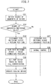
FIG. 7 is a flow chart showing a control routine in control in the CO2 recovery system 20. The illustrated control routine is performed every certain time interval. - First, at step S31, the degree of awakeness of the driver is calculated at the
ECU 40 based on the output of thedriver monitor camera 46, etc. Next, at step S32, it is judged if the degree of awakeness detected at step S31 is lower than a predetermined reference value, that is, if the concentration of the driver is falling. If, at step S32, it is judged that the degree of awakeness of the driver is lower than the reference value, the control routine proceeds to step S33. - At step S33, the discharge
path switching device 25 is set to the return position. Next, at step S34, the flowpath switching device 22 is set to the inside connection position. Next, at step S35, the output of thesuction pump 23 is set based on the CO2 concentration at the inside of thevehicle 1. Accordingly, the flow rate of air at the inside of thevehicle 1 flowing to the CO2 recovery device 21 is controlled based on the CO2 concentration at the inside of thevehicle 1. Next, at step S36, thecooling device 24 is stopped. - On the other hand, if, at step S32, it is judged that the degree of awakeness of the driver is equal to or greater than the reference value, the control routine proceeds to step S37. At step S37, the discharge
path switching device 25 is set to a release position making theexhaust passage 35 communicate with therelease passage 36. Next, at step S38, the normal control shown inFIG. 5 is performed. - Above, preferred embodiments according to the present invention were explained, but the present invention is not limited to these embodiments and may be modified and changed in various ways within the language of the claims.
-
- 1
- vehicle
- 10
- internal combustion engine
- 11
- engine body
- 12
- exhaust pipe
- 20
- CO2 recovery system
- 21
- CO2 recovery device
- 22
- flow path switching device
- 23
- suction pump
- 24
- cooling device
Claims (11)
- A CO2 recovery system (20) used in a vehicle (1), comprising:a CO2 recovery device (21) recovering CO2 contained in inflowing gas; anda flow rate control device controlling flow rates of gases present in a plurality of different regions of the vehicle (1) flowing into the CO2 recovery device (21),wherein the gases present at the plurality of different regions include at least any two among air at an outside of the vehicle (1), air at an inside of the vehicle (1), and exhaust gas discharged from a body (11) of an internal combustion engine of the vehicle (1).
- The CO2 recovery system (20) according to claim 1, wherein the flow rate control device controls the flow rate of air at the outside of the vehicle (1) flowing into the CO2 recovery device (21), based on a CO2 concentration in the air at the outside of the vehicle (1).
- The CO2 recovery system (20) according to claim 1 or 2, wherein the flow rate control device controls the flow rate of air at the inside of the vehicle (1) flowing into the CO2 recovery device (21), based on a CO2 concentration in the air at the inside of the vehicle (1).
- The CO2 recovery system (20) according to any one of claims 1 to 3, whereinthe flow rate control device has a switching device (22) arranged at an upstream side of the CO2 recovery device (21) in a direction of flow of the gas and a pump (23) forcibly sending gases from a plurality of different regions through the switching device (22) to the CO2 recovery device (21), andthe switching device (22) switches the gas to be flowed to the CO2 recovery device (21) among the gases present in the plurality of different regions.
- The CO2 recovery system (20) according to claim 4, whereinthe vehicle (1) has an internal combustion engine (10) having the body (11) of the internal combustion engine and an exhaust passage (12) through which exhaust gas discharged from the body (11) of the internal combustion engine flows,the gases present at the plurality of different regions include exhaust gas discharged from the body (11) of the internal combustion engine, andthe switching device (22) communicates with the exhaust passage (12) so that exhaust gas can flow to the switching device (22) from the exhaust passage (12).
- The CO2 recovery system (20) according to claim 5, whereina first connection passage (32) communicating the exhaust passage (12) with the switching device (22) is provided with a cooling device cooling the gas, anda second connection passage (33) communicating an outside of the vehicle (1) with the switching device (22) and a third connection passage (34) communicating an inside of the vehicle (1) with the switching device (22) are not provided with cooling devices.
- The CO2 recovery system (20) according to claim 5, wherein a communication path communicating the switching device (22) with the CO2 recovery device (21) is provided with a cooling device cooling gas flowing through the communication path.
- The CO2 recovery system (20) according to any one of claims 5 to 7, wherein the flow rate control device controls the flow rate of the exhaust gas, which is discharged from the body (11) of the internal combustion engine, flowing into the CO2 recovery device (21), based on the CO2 concentration in the exhaust gas flowing through the exhaust passage (12).
- The CO2 recovery system (20) according to any one of claims 5 to 8, wherein the flow rate control device is controlled so that when the internal combustion engine (10) is stopped, at least one of air at the outside of the vehicle (1) and air at the inside of the vehicle (1), flows into the CO2 recovery device (21).
- The CO2 recovery system (20) according to any one of claims 4 to 9, wherein when the flow rate control device is controlled so that air at the outside of the vehicle (1) flows into the CO2 recovery device (21), the pump (23) is controlled so that an output of the pump (23) decreases, as the a running speed of the vehicle (1) becomes faster.
- The CO2 recovery system (20) according to any one of claims 1 to 10, whereinthe system (20) further comprises an awakeness degree detection device (46) for detecting a degree of awakeness of a driver,the CO2 recovery device (21) is configured to be able to return gas discharged from the CO2 recovery device (21) to the inside of the vehicle (1), andwhen a degree of awakeness of the driver is lower than a predetermined threshold value, the flow rate control device is controlled so that the air at the inside of the vehicle (1) flows into the CO2 recovery device (21) and the gas discharged from the CO2 recovery device (21) is returned to the inside of the vehicle (1).
Applications Claiming Priority (1)
| Application Number | Priority Date | Filing Date | Title |
|---|---|---|---|
| JP2019109015A JP7111064B2 (en) | 2019-06-11 | 2019-06-11 | CO2 recovery system |
Publications (2)
| Publication Number | Publication Date |
|---|---|
| EP3751105A1 true EP3751105A1 (en) | 2020-12-16 |
| EP3751105B1 EP3751105B1 (en) | 2022-04-06 |
Family
ID=71092265
Family Applications (1)
| Application Number | Title | Priority Date | Filing Date |
|---|---|---|---|
| EP20179283.5A Active EP3751105B1 (en) | 2019-06-11 | 2020-06-10 | Co2 recovery system |
Country Status (4)
| Country | Link |
|---|---|
| US (1) | US11480084B2 (en) |
| EP (1) | EP3751105B1 (en) |
| JP (1) | JP7111064B2 (en) |
| CN (1) | CN112065539B (en) |
Cited By (2)
| Publication number | Priority date | Publication date | Assignee | Title |
|---|---|---|---|---|
| FR3120654A1 (en) * | 2021-03-11 | 2022-09-16 | Renault S.A.S | Replaceable on-board carbon dioxide capture system for internal combustion engine |
| WO2023081125A1 (en) * | 2021-11-02 | 2023-05-11 | Chart Energy & Chemicals, Inc. | Carbon capture system and method with exhaust gas recirculation |
Citations (4)
| Publication number | Priority date | Publication date | Assignee | Title |
|---|---|---|---|---|
| JP2014504695A (en) | 2011-01-20 | 2014-02-24 | サウジ アラビアン オイル カンパニー | In-vehicle recovery and storage of CO2 derived from automobile exhaust gas |
| EP2789377A2 (en) * | 2013-04-12 | 2014-10-15 | Delphi Technologies, Inc. | Carbon dioxide absorbent fluid for a carbon dioxide sequestering system on a vehicle. |
| US20170087963A1 (en) * | 2014-05-30 | 2017-03-30 | Sharp Kabushiki Kaisha | Carbon dioxide concentration control device and apparatus |
| US20190120106A1 (en) * | 2017-10-19 | 2019-04-25 | Saudi Arabian Oil Company | Rotary contactor for vehicle carbon dioxide capture |
Family Cites Families (27)
| Publication number | Priority date | Publication date | Assignee | Title |
|---|---|---|---|---|
| WO2000059748A1 (en) * | 1999-04-02 | 2000-10-12 | Bosch Automotive Systems Corporation | Safety device for vehicle air conditioning system |
| JP4196895B2 (en) * | 2004-07-12 | 2008-12-17 | 株式会社デンソー | Fuel injection device |
| ATE386877T1 (en) * | 2005-03-25 | 2008-03-15 | Delphi Tech Inc | METHOD FOR DETERMINING PARAMETERS OF AN INJECTION SYSTEM |
| KR101472538B1 (en) * | 2007-01-10 | 2014-12-16 | 코닌클리케 필립스 엔.브이. | Controlling system for controlling an air handling system |
| JP4946658B2 (en) * | 2007-06-26 | 2012-06-06 | マツダ株式会社 | Exhaust gas purification catalyst device |
| JP2010101303A (en) * | 2008-09-25 | 2010-05-06 | Toyota Motor Corp | Exhaust emission control device of internal combustion engine |
| WO2010100739A1 (en) * | 2009-03-05 | 2010-09-10 | 株式会社西部技研 | Air conditioner |
| ES2763206T3 (en) * | 2010-04-30 | 2020-05-27 | Peter Eisenberger | Carbon dioxide capture method |
| JP2012006415A (en) * | 2010-06-22 | 2012-01-12 | Higashi Nippon Transportec Kk | Air conditioner for railroad vehicle |
| CN103402795B (en) | 2011-02-24 | 2016-01-20 | 松下知识产权经营株式会社 | Air conditioner for vehicles |
| CN105114213B (en) | 2011-03-08 | 2017-08-29 | 丰田自动车株式会社 | The vehicle of system is generated with mixed gas |
| EP2685076B1 (en) | 2011-03-08 | 2016-05-11 | Toyota Jidosha Kabushiki Kaisha | Vehicle with mixed gas generating system, and vehicle with fuel producing system |
| WO2012160735A1 (en) * | 2011-05-26 | 2012-11-29 | パナソニック株式会社 | Air conditioning device for vehicle |
| KR20140038717A (en) * | 2012-09-21 | 2014-03-31 | 김수종 | Apparatus for preventing drowsiness driving by using co2 sensing and body sensing |
| JP6008764B2 (en) * | 2013-03-15 | 2016-10-19 | 三菱重工業株式会社 | Working gas circulation engine system |
| KR20140114237A (en) * | 2013-03-18 | 2014-09-26 | 한라비스테온공조 주식회사 | Blower unit for air conditioner of vehicle |
| JP6052222B2 (en) * | 2013-06-18 | 2016-12-27 | 株式会社デンソー | Thermal management system for vehicles |
| CN103967675A (en) * | 2014-04-21 | 2014-08-06 | 北京理工大学 | Comprehensive collection system for diesel engine high pressure common rail oil atomizer |
| JP6269307B2 (en) * | 2014-05-13 | 2018-01-31 | 株式会社デンソー | Air conditioner for vehicles |
| EP3191217A1 (en) * | 2014-09-12 | 2017-07-19 | Johnson Matthey Public Limited Company | System and process for carbon dioxide removal of air of passenger cabins of vehicles |
| JP2017206145A (en) | 2016-05-19 | 2017-11-24 | サンデンホールディングス株式会社 | Vehicle air conditioner |
| JP6680626B2 (en) * | 2016-06-14 | 2020-04-15 | 本田技研工業株式会社 | Vehicle air conditioner |
| NL2018407B1 (en) * | 2017-02-22 | 2018-09-17 | Skytree B V | Improved process and apparatus for the removal of metabolic carbon dioxide from a confined space |
| JP2019098872A (en) * | 2017-11-30 | 2019-06-24 | 本田技研工業株式会社 | Vehicular air cleaner |
| JP6655057B2 (en) * | 2017-11-30 | 2020-02-26 | 本田技研工業株式会社 | Vehicle air purification device |
| JP6709773B2 (en) * | 2017-11-30 | 2020-06-17 | 本田技研工業株式会社 | Vehicle air purification device |
| CN108412624B (en) * | 2018-01-29 | 2020-08-25 | 中国第一汽车股份有限公司 | Method for controlling a fuel injector |
-
2019
- 2019-06-11 JP JP2019109015A patent/JP7111064B2/en active Active
-
2020
- 2020-05-28 US US16/885,274 patent/US11480084B2/en active Active
- 2020-06-10 EP EP20179283.5A patent/EP3751105B1/en active Active
- 2020-06-10 CN CN202010522598.6A patent/CN112065539B/en active Active
Patent Citations (4)
| Publication number | Priority date | Publication date | Assignee | Title |
|---|---|---|---|---|
| JP2014504695A (en) | 2011-01-20 | 2014-02-24 | サウジ アラビアン オイル カンパニー | In-vehicle recovery and storage of CO2 derived from automobile exhaust gas |
| EP2789377A2 (en) * | 2013-04-12 | 2014-10-15 | Delphi Technologies, Inc. | Carbon dioxide absorbent fluid for a carbon dioxide sequestering system on a vehicle. |
| US20170087963A1 (en) * | 2014-05-30 | 2017-03-30 | Sharp Kabushiki Kaisha | Carbon dioxide concentration control device and apparatus |
| US20190120106A1 (en) * | 2017-10-19 | 2019-04-25 | Saudi Arabian Oil Company | Rotary contactor for vehicle carbon dioxide capture |
Cited By (2)
| Publication number | Priority date | Publication date | Assignee | Title |
|---|---|---|---|---|
| FR3120654A1 (en) * | 2021-03-11 | 2022-09-16 | Renault S.A.S | Replaceable on-board carbon dioxide capture system for internal combustion engine |
| WO2023081125A1 (en) * | 2021-11-02 | 2023-05-11 | Chart Energy & Chemicals, Inc. | Carbon capture system and method with exhaust gas recirculation |
Also Published As
| Publication number | Publication date |
|---|---|
| EP3751105B1 (en) | 2022-04-06 |
| JP7111064B2 (en) | 2022-08-02 |
| CN112065539A (en) | 2020-12-11 |
| CN112065539B (en) | 2022-04-26 |
| US20200391575A1 (en) | 2020-12-17 |
| JP2020200802A (en) | 2020-12-17 |
| US11480084B2 (en) | 2022-10-25 |
Similar Documents
| Publication | Publication Date | Title |
|---|---|---|
| JP7088144B2 (en) | Vehicle control device equipped with CO2 capture device | |
| EP3751105B1 (en) | Co2 recovery system | |
| US6964157B2 (en) | Exhaust emission control system and method for removal and storage of vehicle exhaust gas nitrogen oxides during cold operation | |
| JP2006509137A5 (en) | ||
| US11035280B2 (en) | CO2 trapping device | |
| US11654392B2 (en) | Vehicle and CO2 recovery method | |
| EP3708238B1 (en) | Adsorption refrigeration system for the production of demineralized water aboard a motor vehicle, motor vehicle and method for producing demineralized water aboard a motor vehicle | |
| US11319856B2 (en) | Control device controlling CO2 recovery device | |
| US20180274464A1 (en) | Motor vehicle including a lean nox trap regeneration system and method for regeneration | |
| JP2010101303A (en) | Exhaust emission control device of internal combustion engine | |
| JP2008151103A (en) | Exhaust emission control system of internal combustion engine | |
| JP2011001876A (en) | Exhaust control device of internal combustion engine | |
| JP2009293471A (en) | Exhaust emission control device | |
| JP2003314381A (en) | Evaporation fuel recovery device | |
| JP2008232055A (en) | Exhaust emission control system for internal combustion engine | |
| Aiba et al. | Vehicle and CO 2 recovery method | |
| WO2024004285A1 (en) | Evaporated fuel treatment device | |
| JP6119449B2 (en) | Exhaust gas purification device | |
| JP4992586B2 (en) | Exhaust purification equipment | |
| JP2008215135A (en) | Exhaust emission control device for internal combustion engine | |
| JP2022153036A (en) | Co2 separation device of internal combustion engine | |
| JP2022152472A (en) | Co2 separation device of internal combustion engine | |
| JP2024022736A (en) | Flow path control device and flow path control method for CO2 storage in a vehicle | |
| JP2019190418A (en) | Exhaust emission control device and vehicle | |
| JP2019190419A (en) | Exhaust emission control device and vehicle |
Legal Events
| Date | Code | Title | Description |
|---|---|---|---|
| PUAI | Public reference made under article 153(3) epc to a published international application that has entered the european phase |
Free format text: ORIGINAL CODE: 0009012 |
|
| STAA | Information on the status of an ep patent application or granted ep patent |
Free format text: STATUS: REQUEST FOR EXAMINATION WAS MADE |
|
| 17P | Request for examination filed |
Effective date: 20200624 |
|
| AK | Designated contracting states |
Kind code of ref document: A1 Designated state(s): AL AT BE BG CH CY CZ DE DK EE ES FI FR GB GR HR HU IE IS IT LI LT LU LV MC MK MT NL NO PL PT RO RS SE SI SK SM TR |
|
| AX | Request for extension of the european patent |
Extension state: BA ME |
|
| GRAP | Despatch of communication of intention to grant a patent |
Free format text: ORIGINAL CODE: EPIDOSNIGR1 |
|
| STAA | Information on the status of an ep patent application or granted ep patent |
Free format text: STATUS: GRANT OF PATENT IS INTENDED |
|
| GRAJ | Information related to disapproval of communication of intention to grant by the applicant or resumption of examination proceedings by the epo deleted |
Free format text: ORIGINAL CODE: EPIDOSDIGR1 |
|
| GRAP | Despatch of communication of intention to grant a patent |
Free format text: ORIGINAL CODE: EPIDOSNIGR1 |
|
| INTG | Intention to grant announced |
Effective date: 20211011 |
|
| RIN1 | Information on inventor provided before grant (corrected) |
Inventor name: YOKOYAMA, DAIKI Inventor name: MIYAGAWA, JUN |
|
| INTG | Intention to grant announced |
Effective date: 20211027 |
|
| GRAS | Grant fee paid |
Free format text: ORIGINAL CODE: EPIDOSNIGR3 |
|
| GRAA | (expected) grant |
Free format text: ORIGINAL CODE: 0009210 |
|
| STAA | Information on the status of an ep patent application or granted ep patent |
Free format text: STATUS: THE PATENT HAS BEEN GRANTED |
|
| AK | Designated contracting states |
Kind code of ref document: B1 Designated state(s): AL AT BE BG CH CY CZ DE DK EE ES FI FR GB GR HR HU IE IS IT LI LT LU LV MC MK MT NL NO PL PT RO RS SE SI SK SM TR |
|
| REG | Reference to a national code |
Ref country code: GB Ref legal event code: FG4D |
|
| REG | Reference to a national code |
Ref country code: CH Ref legal event code: EP |
|
| REG | Reference to a national code |
Ref country code: AT Ref legal event code: REF Ref document number: 1481533 Country of ref document: AT Kind code of ref document: T Effective date: 20220415 |
|
| REG | Reference to a national code |
Ref country code: IE Ref legal event code: FG4D |
|
| REG | Reference to a national code |
Ref country code: DE Ref legal event code: R096 Ref document number: 602020002528 Country of ref document: DE |
|
| REG | Reference to a national code |
Ref country code: LT Ref legal event code: MG9D |
|
| REG | Reference to a national code |
Ref country code: NL Ref legal event code: MP Effective date: 20220406 |
|
| REG | Reference to a national code |
Ref country code: AT Ref legal event code: MK05 Ref document number: 1481533 Country of ref document: AT Kind code of ref document: T Effective date: 20220406 |
|
| PG25 | Lapsed in a contracting state [announced via postgrant information from national office to epo] |
Ref country code: NL Free format text: LAPSE BECAUSE OF FAILURE TO SUBMIT A TRANSLATION OF THE DESCRIPTION OR TO PAY THE FEE WITHIN THE PRESCRIBED TIME-LIMIT Effective date: 20220406 |
|
| PG25 | Lapsed in a contracting state [announced via postgrant information from national office to epo] |
Ref country code: SE Free format text: LAPSE BECAUSE OF FAILURE TO SUBMIT A TRANSLATION OF THE DESCRIPTION OR TO PAY THE FEE WITHIN THE PRESCRIBED TIME-LIMIT Effective date: 20220406 Ref country code: PT Free format text: LAPSE BECAUSE OF FAILURE TO SUBMIT A TRANSLATION OF THE DESCRIPTION OR TO PAY THE FEE WITHIN THE PRESCRIBED TIME-LIMIT Effective date: 20220808 Ref country code: NO Free format text: LAPSE BECAUSE OF FAILURE TO SUBMIT A TRANSLATION OF THE DESCRIPTION OR TO PAY THE FEE WITHIN THE PRESCRIBED TIME-LIMIT Effective date: 20220706 Ref country code: LT Free format text: LAPSE BECAUSE OF FAILURE TO SUBMIT A TRANSLATION OF THE DESCRIPTION OR TO PAY THE FEE WITHIN THE PRESCRIBED TIME-LIMIT Effective date: 20220406 Ref country code: HR Free format text: LAPSE BECAUSE OF FAILURE TO SUBMIT A TRANSLATION OF THE DESCRIPTION OR TO PAY THE FEE WITHIN THE PRESCRIBED TIME-LIMIT Effective date: 20220406 Ref country code: GR Free format text: LAPSE BECAUSE OF FAILURE TO SUBMIT A TRANSLATION OF THE DESCRIPTION OR TO PAY THE FEE WITHIN THE PRESCRIBED TIME-LIMIT Effective date: 20220707 Ref country code: FI Free format text: LAPSE BECAUSE OF FAILURE TO SUBMIT A TRANSLATION OF THE DESCRIPTION OR TO PAY THE FEE WITHIN THE PRESCRIBED TIME-LIMIT Effective date: 20220406 Ref country code: ES Free format text: LAPSE BECAUSE OF FAILURE TO SUBMIT A TRANSLATION OF THE DESCRIPTION OR TO PAY THE FEE WITHIN THE PRESCRIBED TIME-LIMIT Effective date: 20220406 Ref country code: BG Free format text: LAPSE BECAUSE OF FAILURE TO SUBMIT A TRANSLATION OF THE DESCRIPTION OR TO PAY THE FEE WITHIN THE PRESCRIBED TIME-LIMIT Effective date: 20220706 Ref country code: AT Free format text: LAPSE BECAUSE OF FAILURE TO SUBMIT A TRANSLATION OF THE DESCRIPTION OR TO PAY THE FEE WITHIN THE PRESCRIBED TIME-LIMIT Effective date: 20220406 |
|
| PG25 | Lapsed in a contracting state [announced via postgrant information from national office to epo] |
Ref country code: RS Free format text: LAPSE BECAUSE OF FAILURE TO SUBMIT A TRANSLATION OF THE DESCRIPTION OR TO PAY THE FEE WITHIN THE PRESCRIBED TIME-LIMIT Effective date: 20220406 Ref country code: PL Free format text: LAPSE BECAUSE OF FAILURE TO SUBMIT A TRANSLATION OF THE DESCRIPTION OR TO PAY THE FEE WITHIN THE PRESCRIBED TIME-LIMIT Effective date: 20220406 Ref country code: LV Free format text: LAPSE BECAUSE OF FAILURE TO SUBMIT A TRANSLATION OF THE DESCRIPTION OR TO PAY THE FEE WITHIN THE PRESCRIBED TIME-LIMIT Effective date: 20220406 Ref country code: IS Free format text: LAPSE BECAUSE OF FAILURE TO SUBMIT A TRANSLATION OF THE DESCRIPTION OR TO PAY THE FEE WITHIN THE PRESCRIBED TIME-LIMIT Effective date: 20220806 |
|
| REG | Reference to a national code |
Ref country code: DE Ref legal event code: R097 Ref document number: 602020002528 Country of ref document: DE |
|
| PG25 | Lapsed in a contracting state [announced via postgrant information from national office to epo] |
Ref country code: SM Free format text: LAPSE BECAUSE OF FAILURE TO SUBMIT A TRANSLATION OF THE DESCRIPTION OR TO PAY THE FEE WITHIN THE PRESCRIBED TIME-LIMIT Effective date: 20220406 Ref country code: SK Free format text: LAPSE BECAUSE OF FAILURE TO SUBMIT A TRANSLATION OF THE DESCRIPTION OR TO PAY THE FEE WITHIN THE PRESCRIBED TIME-LIMIT Effective date: 20220406 Ref country code: RO Free format text: LAPSE BECAUSE OF FAILURE TO SUBMIT A TRANSLATION OF THE DESCRIPTION OR TO PAY THE FEE WITHIN THE PRESCRIBED TIME-LIMIT Effective date: 20220406 Ref country code: MC Free format text: LAPSE BECAUSE OF FAILURE TO SUBMIT A TRANSLATION OF THE DESCRIPTION OR TO PAY THE FEE WITHIN THE PRESCRIBED TIME-LIMIT Effective date: 20220406 Ref country code: EE Free format text: LAPSE BECAUSE OF FAILURE TO SUBMIT A TRANSLATION OF THE DESCRIPTION OR TO PAY THE FEE WITHIN THE PRESCRIBED TIME-LIMIT Effective date: 20220406 Ref country code: DK Free format text: LAPSE BECAUSE OF FAILURE TO SUBMIT A TRANSLATION OF THE DESCRIPTION OR TO PAY THE FEE WITHIN THE PRESCRIBED TIME-LIMIT Effective date: 20220406 Ref country code: CZ Free format text: LAPSE BECAUSE OF FAILURE TO SUBMIT A TRANSLATION OF THE DESCRIPTION OR TO PAY THE FEE WITHIN THE PRESCRIBED TIME-LIMIT Effective date: 20220406 |
|
| PLBE | No opposition filed within time limit |
Free format text: ORIGINAL CODE: 0009261 |
|
| STAA | Information on the status of an ep patent application or granted ep patent |
Free format text: STATUS: NO OPPOSITION FILED WITHIN TIME LIMIT |
|
| REG | Reference to a national code |
Ref country code: BE Ref legal event code: MM Effective date: 20220630 |
|
| 26N | No opposition filed |
Effective date: 20230110 |
|
| PG25 | Lapsed in a contracting state [announced via postgrant information from national office to epo] |
Ref country code: AL Free format text: LAPSE BECAUSE OF FAILURE TO SUBMIT A TRANSLATION OF THE DESCRIPTION OR TO PAY THE FEE WITHIN THE PRESCRIBED TIME-LIMIT Effective date: 20220406 |
|
| PG25 | Lapsed in a contracting state [announced via postgrant information from national office to epo] |
Ref country code: LU Free format text: LAPSE BECAUSE OF NON-PAYMENT OF DUE FEES Effective date: 20220610 Ref country code: IE Free format text: LAPSE BECAUSE OF NON-PAYMENT OF DUE FEES Effective date: 20220610 |
|
| PG25 | Lapsed in a contracting state [announced via postgrant information from national office to epo] |
Ref country code: SI Free format text: LAPSE BECAUSE OF FAILURE TO SUBMIT A TRANSLATION OF THE DESCRIPTION OR TO PAY THE FEE WITHIN THE PRESCRIBED TIME-LIMIT Effective date: 20220406 Ref country code: BE Free format text: LAPSE BECAUSE OF NON-PAYMENT OF DUE FEES Effective date: 20220630 |
|
| P01 | Opt-out of the competence of the unified patent court (upc) registered |
Effective date: 20230427 |
|
| REG | Reference to a national code |
Ref country code: DE Ref legal event code: R084 Ref document number: 602020002528 Country of ref document: DE |
|
| PGFP | Annual fee paid to national office [announced via postgrant information from national office to epo] |
Ref country code: FR Payment date: 20230510 Year of fee payment: 4 Ref country code: DE Payment date: 20230502 Year of fee payment: 4 |
|
| PG25 | Lapsed in a contracting state [announced via postgrant information from national office to epo] |
Ref country code: IT Free format text: LAPSE BECAUSE OF FAILURE TO SUBMIT A TRANSLATION OF THE DESCRIPTION OR TO PAY THE FEE WITHIN THE PRESCRIBED TIME-LIMIT Effective date: 20220406 |
|
| REG | Reference to a national code |
Ref country code: CH Ref legal event code: PL |
|
| PG25 | Lapsed in a contracting state [announced via postgrant information from national office to epo] |
Ref country code: MK Free format text: LAPSE BECAUSE OF FAILURE TO SUBMIT A TRANSLATION OF THE DESCRIPTION OR TO PAY THE FEE WITHIN THE PRESCRIBED TIME-LIMIT Effective date: 20220406 Ref country code: CY Free format text: LAPSE BECAUSE OF FAILURE TO SUBMIT A TRANSLATION OF THE DESCRIPTION OR TO PAY THE FEE WITHIN THE PRESCRIBED TIME-LIMIT Effective date: 20220406 Ref country code: CH Free format text: LAPSE BECAUSE OF NON-PAYMENT OF DUE FEES Effective date: 20230630 |