EP3750785A1 - Vehicle side body structure, vehicle body structure, and vehicle - Google Patents
Vehicle side body structure, vehicle body structure, and vehicle Download PDFInfo
- Publication number
- EP3750785A1 EP3750785A1 EP20162988.8A EP20162988A EP3750785A1 EP 3750785 A1 EP3750785 A1 EP 3750785A1 EP 20162988 A EP20162988 A EP 20162988A EP 3750785 A1 EP3750785 A1 EP 3750785A1
- Authority
- EP
- European Patent Office
- Prior art keywords
- vehicle
- body structure
- upper member
- side body
- vehicle side
- Prior art date
- Legal status (The legal status is an assumption and is not a legal conclusion. Google has not performed a legal analysis and makes no representation as to the accuracy of the status listed.)
- Withdrawn
Links
- 230000003014 reinforcing effect Effects 0.000 claims abstract description 65
- 238000005452 bending Methods 0.000 claims abstract description 49
- 229910000831 Steel Inorganic materials 0.000 claims abstract description 14
- 239000010959 steel Substances 0.000 claims abstract description 14
- 238000005192 partition Methods 0.000 claims abstract 2
- 230000008878 coupling Effects 0.000 claims description 14
- 238000010168 coupling process Methods 0.000 claims description 14
- 238000005859 coupling reaction Methods 0.000 claims description 14
- 239000000463 material Substances 0.000 description 8
- 230000000694 effects Effects 0.000 description 6
- 238000005516 engineering process Methods 0.000 description 4
- 239000013585 weight reducing agent Substances 0.000 description 3
- 230000000052 comparative effect Effects 0.000 description 2
- 238000010586 diagram Methods 0.000 description 2
- 238000000465 moulding Methods 0.000 description 2
- 230000002787 reinforcement Effects 0.000 description 2
- 230000001419 dependent effect Effects 0.000 description 1
- 238000006073 displacement reaction Methods 0.000 description 1
- 230000002093 peripheral effect Effects 0.000 description 1
- 238000000638 solvent extraction Methods 0.000 description 1
- 230000000087 stabilizing effect Effects 0.000 description 1
Images




Classifications
-
- B—PERFORMING OPERATIONS; TRANSPORTING
- B62—LAND VEHICLES FOR TRAVELLING OTHERWISE THAN ON RAILS
- B62D—MOTOR VEHICLES; TRAILERS
- B62D25/00—Superstructure or monocoque structure sub-units; Parts or details thereof not otherwise provided for
- B62D25/04—Door pillars ; windshield pillars
-
- B—PERFORMING OPERATIONS; TRANSPORTING
- B62—LAND VEHICLES FOR TRAVELLING OTHERWISE THAN ON RAILS
- B62D—MOTOR VEHICLES; TRAILERS
- B62D25/00—Superstructure or monocoque structure sub-units; Parts or details thereof not otherwise provided for
- B62D25/02—Side panels
- B62D25/025—Side sills thereof
Definitions
- the present invention relates to a vehicle side body structure, a vehicle body structure, and a vehicle.
- the present invention relates to a vehicle side body structure having a pillar member including an upper member, a lower member, and a reinforcing member.
- each of the upper member and the lower member has a side wall part extending along the side surface of the body and a pair of front and rear vertical wall parts extending toward the inside in a vehicle width direction from the front and rear ends of the side wall part.
- the pair of vertical wall parts of the lower member is inclined so that the interval of the pair of vertical wall parts is larger toward the inside in the vehicle width direction and the inclination angle of the vertical wall parts of the lower member is larger than in the vertical wall parts of the upper member.
- the pair of vertical wall parts of the lower member is inclined so that the interval of the pair of vertical wall parts is larger toward the inside in the vehicle width direction in the vehicle side body structure in PTL 1, the width in the vehicle front-rear direction of the lower member becomes large, thereby increasing the size of the center pillar.
- plate members having different thicknesses may be joined to each other, plate members may be partially superposed on each other, or a plate member such as a high-tensile material that has different strength may be joined. Even in such a case, conditions having effects on the bending rigidity of the center pillar need to be set appropriately in advance.
- An object of the present invention is to reduce the amount of intrusion into the vehicle interior at the time of a side collision, and achieve weight reduction of a pillar member.
- a vehicle side body structure including a pillar member including an upper member, a lower member that is joined to the upper member and has a rigidity lower than a rigidity of the upper member, and a reinforcing member provided in the upper member, the pillar member partitioning a side part opening of a vehicle body into a front part and a rear part, in which a lower half of the reinforcing member is shaped to have a smaller bending rigidity against bending to an inside in a vehicle width direction toward a lower end of the reinforcing member.
- the rigidity of the upper member is set higher than the rigidity of the lower member and the reinforcing member is provided in this upper member, so the upper member has a rigidity higher than a rigidity of the lower member. Since the lower half of the reinforcing member is shaped to have a smaller bending rigidity against bending to the inside in the vehicle width direction toward the lower end of the reinforcing member, the bending rigidity of the lower member is set smaller than the bending rigidity of the upper member and the reinforcing member while ensuring the continuity of the bending rigidity across the whole length of the upper member. Since the bending rigidity of the upper member can be adjusted via the reinforcing member, weight reduction in the pillar member can be achieved.
- the angle of bending deformation of the lower member toward the vehicle interior is larger than the angle of bending deformation of the upper member and a portion near the border between the upper member and the lower member makes intrusion into the vehicle interior at a maximum. Since the portion near the border between the upper member and the lower member comes close to the lower part by setting the length of the upper member longer than the length of the lower member, the amount of intrusion of the pillar member into the vehicle interior at the time of a side collision can be reduced.
- the present invention may have various preferred embodiments described below.
- the reinforcing member is set to have the bending rigidity against the bending to the inside in the vehicle width direction via a front-rear width in a vehicle front-rear direction.
- the bending rigidity can be set freely by setting the front-rear width of the reinforcing member.
- the upper member has a pair of front and rear ridge parts extending in a vehicle up-down direction
- the reinforcing member has a wide part provided across the pair of front and rear ridge parts and a narrow part that extends downward from the wide part and covers one of the pair of front and rear ridge parts.
- the upper member can be reinforced by using the reinforcing member at minimum while ensuring the integrity of the reinforcing member.
- the pillar member has one or a plurality of hinge coupling parts to which a hinge that supports a door is coupled, a portion of the reinforcing member that corresponds to an uppermost one of the hinge coupling parts is formed by a lower end portion of the wide part, and the narrow part extends downward from the lower end portion of the wide part.
- a vertical length of the upper member is longer than a vertical length of the lower member.
- the upper member and the lower member are formed by plate members made of high-tensile steel.
- the upper member is thicker than the lower member.
- the reinforcing member is formed by a plate member made of high-tensile steel having a tensile strength.
- the tensile strength of the reinforcing member is higher than tensile strengths of the plate members of the upper member and the lower member.
- a front-rear width in the front-rear direction of the wide part is set to be larger than a front-rear width in the front-rear direction of the narrow part.
- the lower member is formed by a plate member made of normal steel.
- a vehicle body structure includes the above vehicle side body structure.
- a vehicle includes a side part opening and the above vehicle side body structure.
- Figs. 1 to 3 illustrate a vehicle side body structure 1 of a 4-door sedan car
- this vehicle side body structure 1 has a side part opening 2
- this side part opening 2 is partitioned into a front side opening 2a and a rear side opening 2b by a pillar member 3 of a center pillar (not illustrated), and the front side opening 2a and the rear side opening 2b are closed by side doors 4 in an openable and closable manner.
- the side door for closing the front side opening 2a is not illustrated in Fig. 1 .
- arrows F, L, and U indicate the front side, the left side, and the upper side.
- vehicle side body structure 1 on the right side of an automobile is assumed as an example.
- the vehicle side body structure 1 has a roof side rail 5 and a side sill 6 that extend in the front-rear direction and these members form the upper side part and the lower side part of the side part opening 2.
- the middle parts in the front-rear direction of the roof side rail 5 and the side sill 6 are coupled to each other by the pillar member 3 extending in the up-down direction.
- the center pillar includes the pillar member 3 illustrated in Figs. 1 and 2 , an inner panel (not illustrated) jointed to the inner surface inside in the vehicle width direction of this pillar member 3, and an outer panel (not illustrated) that covers the outer surface side of the pillar member 3.
- the center pillar is particularly formed to have a larger front-rear width in the front-rear direction toward the lower portion.
- the upper end portion of the pillar member 3 is joined to the roof side rail 5 and the lower end portion of the pillar member 3 is joined to the side sill 6.
- the pillar member 3 includes an upper member 7, a lower member 8 joined to the upper member 7 and having a rigidity lower than a rigidity of the upper member 7, and the lower end of the upper member 7 and the upper end of the lower member 8 are welded to each other in a joint line 9.
- the vertical length of the upper member 7 is particularly longer than the vertical length of the lower member 8 and is, for example, approximately 3/4 of the whole length of the pillar member 3 and the vertical length of the lower member 8 is approximately 1/4 of the while length of the pillar member 3.
- the ratios described are not limited to 3/4 and 1/4.
- the upper member 7 and the lower member 8 are particularly formed by thin plate members made of high-tensile steel, the upper member 7 is particularly formed by a plate member thicker than in the lower member 8, and the upper member 7 has a rigidity higher than a rigidity of the lower member 8.
- the upper member 7 has a side wall part 7a oriented in the vehicle front-rear direction, a pair of front and rear vertical wall parts 7b and 7c extending to the inside in the vehicle width direction from the front and rear ends of the side wall part 7a, and the joint parts between the side wall part 7a and the pair of vertical wall parts 7b and 7c are a pair of front and rear ridge parts 7d and 7e extending in the vehicle up-down direction.
- Figs. 6 to 8 and 10 the upper member 7 has a side wall part 7a oriented in the vehicle front-rear direction, a pair of front and rear vertical wall parts 7b and 7c extending to the inside in the vehicle width direction from the front and rear ends of the side wall part 7a, and the joint parts between the side wall part 7a and the pair of vertical wall parts 7b and 7c are a pair of front and rear ridge parts 7d and 7e extending in the vehicle up-down direction.
- the lower member 8 has a side wall part 8a oriented in the vehicle front-rear direction and a pair of front and rear vertical wall parts 8b and 8c extending to the inside in the vehicle width direction from the front and rear ends of the side wall part 8a and the joint parts between the side wall part 8a and the pair of vertical wall parts 8b and 8c are a pair of front and rear ridge parts 8d and 8e extending in the vehicle up-down direction.
- a reinforcing member 10 is welded to the outer surface in the vehicle width direction of the upper member 7.
- This reinforcing member 10 is particularly formed by a thin plate member made of high-tensile steel with a higher tensile strength than tensile strengths of the plate members the upper member 7 and the lower member 8.
- the material of the reinforcing member 10 is welded to the surface of the material of the upper member 7, the upper end of the material of the lower member 8 is welded to the lower end of the material of the upper member 7, and these materials are press-molded by tailored blank technology.
- the reinforcing member 10 particularly has a wide part 11 that straddles the pair of front and rear ridge parts 7d and 7e of the upper member 7 and a narrow part 12 that extends downward from the wide part 11 and covers only one of the front and rear ridge parts (rear ridge part 7e in the embodiment) 7d and 7e.
- the front-rear width in the front-rear direction of the wide part 11 is particularly set larger than the front-rear width in the front-rear direction of the narrow part 12.
- the vertical length of the wide part 11 is, for example, approximately 3/4 of the whole length of the reinforcing member 10 and the vertical length of the narrow part 12 is, for example, approximately 1/4 of the whole length of the reinforcing member 10.
- a triangular opening 10a is formed in the portion of the wide part 11 close to the upper end and three long openings 10b are formed in series with bridge parts 10c provided therebetween in the portion extending downward from this opening 10a.
- the bending rigidity of the reinforcing member 10 against bending to the inside in the vehicle width direction is particularly adjusted via the openings 10a and 10b described above.
- the lower half of the reinforcing member 10 is shaped to have a gradually smaller bending rigidity against bending to the inside in the vehicle width direction toward the lower end of the reinforcing member 10.
- the front-rear width of the side wall part 7a of the upper member 7 has effects on the bending rigidity of the upper member 7, the front-rear width of the side wall part 7a is particularly maximized in the vicinity of a hinge coupling part 13 and reduces toward the lower part from the vicinity of the hinge coupling part 13.
- the pillar member 3 has two hinge coupling parts 13 and 14 to which a hinge that supports the side door 4 is coupled, and the portion of the reinforcing member 10 that corresponds to the upper hinge coupling part 13 is formed by the lower end portion of the wide part 11 and the narrow part 12 extends downward from the lower end portion of this wide part 11.
- the lower end portion of the wide part 11 has two bolt holes 10d for the upper hinge coupling part 13.
- the lower hinge coupling part 14 is formed in the vicinity of the upper end of the lower member 8.
- an impact bar 15 that ensures the rigidity of the portion of the side door 4 near the beltline and transmits a side collision load to the pillar member 3 is provided.
- a front end portion 15a of the impact bar 15 overlaps with the upper member 7 and the lower member 8 in vehicle side view.
- the front end portion 15a of the impact bar 15 overlaps with the vertical wall parts 7c and 8c on the vehicle rear side of the upper member 7 and the lower member 8 in vehicle side view.
- the front end portion 15a of the impact bar 15 has a region 16a of the upper member 7 in which the reinforcing member 10 is present, a region 16b of the upper member 7 in which the reinforcing member 10 is not present, and a region 16c that covers the lower member 8 in vehicle side view.
- the pillar member 3 has a harness pass-through opening 17 through which harnesses for a power window and a speaker pass and the front end portion 15a of the impact bar 15 covers at least a part of the harness pass-through opening 17 in vehicle side view to protect the harnesses.
- the opening 17 is formed in the vicinity of the lower end of the upper member 7, that is, the vicinity of the joint line 9 and this opening 17 appropriately reduces the bending rigidity of the upper member 7.
- the rigidity of the upper member 7 is particularly set higher than the rigidity of the lower member 8 and this upper member 7 has particularly the reinforcing member 10 made of high-tensile steel, the rigidity of the upper member 7 and the reinforcing member 10 is higher than that of the lower member 8. Since the lower half of the reinforcing member 10 is shaped to have a smaller bending rigidity against bending to the inside in the vehicle width direction toward the lower end of the reinforcing member 10, the bending rigidity of the lower member 8 is set smaller than the bending rigidity of the upper member 7 and the reinforcing member 10 while ensuring the continuity of the bending rigidity across the whole length of the upper member 7. Since the bending rigidity of the upper member 7 can be adjusted via the reinforcing member 10, weight reduction in the pillar member 3 can be achieved.
- the angle of bending deformation of the lower member 8 toward the vehicle interior is larger than the angle of bending deformation of the upper member 7 and a portion near the border between the upper member 7 and the lower member 8 makes intrusion into the vehicle interior at a maximum.
- the border portion between the upper member 7 and the lower member 8 comes close to the lower part by setting the length of the upper member 7 longer than the length of the lower member 8, the maximum amount of intrusion of the pillar member 3 into the vehicle interior at the time of a side collision can be reduced.
- the roles of the upper member 7 and the lower member 8 at the time of a side collision are divided and the difference between the strengths thereof do not become so large, the behavior of the pillar member 3 at the time of a side collision becomes stable.
- the deformation mode of the pillar member 3 at this time enters the state in which calmly bending occurs in a border part A between the upper member 7 and the lower member 8, the upper member 7 undergoes bending deformation toward the vehicle interior and the lower member 8 is deformed toward the vehicle interior mainly in a crashed manner, and the angle of the bending deformation of the lower member 8 is larger than the angle of the bending deformation of the upper member 7. Accordingly, an amount D of intrusion of the pillar member 3 into the vehicle interior in the border part A is maximized.
- Fig. 13 illustrates the deformation mode according to a comparative example in which a middle part of a pillar member 3' of a center pillar 3P' is sharply bent.
- An amount D' of intrusion of the pillar member 3' into the vehicle interior in this case is significantly larger than the amount D of intrusion in Fig. 12 .
- the bending rigidity of the reinforcing member 10 against bending to the inside in the vehicle width direction is particularly set via the front-rear width in the vehicle front-rear direction, the bending rigidity can be set freely by adjusting the front-rear width of the reinforcing member 10.
- the upper member 7 can be reinforced by using the reinforcing member 10 at minimum while ensuring the integrity of the reinforcing member 10.
- the portion of the reinforcing member 10 corresponding to the upper hinge coupling part 13 is formed by the lower end portion of the wide part 11 and the narrow part 12 extends downward from the lower end portion of this wide part 11, the above effects can be obtained while suppressing intrusion of the pillar member 3 near the beltline corresponding to the upper hinge coupling part 13 into the vehicle interior at the time of a side collision.
- the collision load applied to the impact bar 15 at the time of a side collision acts on both the upper member 7 and the lower member 8 without concentrating on one of the upper member 7 and the lower member 8, thereby stabilizing the behavior of the pillar member 3 at the time of a side collision and deforming the pillar member 3 in a desired deformation mode.
- the pillar member 3 can be deformed in a desired deformation mode by distributing the load from the impact bar 15 to the upper member 7 and the lower member 8 at the time of a side collision.
- the pillar member 3 has the harness pass-through opening 17 and the front end portion 15a of the impact bar 15 covers at least a part of the harness pass-through opening 17 in vehicle side view, the harnesses that pass through the opening 17 can be protected by the front end portion 15a of the impact bar 15.
- the load at the time of a side collision can be surely transmitted to the upper member 7 and the lower member 8 by transmitting the load from the front end portion 15a of the impact bar 15 to the vertical wall parts 7c and 8c on the vehicle rear side of the upper member 7 and the lower member 8 at the time of a side collision.
Landscapes
- Engineering & Computer Science (AREA)
- Chemical & Material Sciences (AREA)
- Combustion & Propulsion (AREA)
- Transportation (AREA)
- Mechanical Engineering (AREA)
- Body Structure For Vehicles (AREA)
Abstract
Description
- The present invention relates to a vehicle side body structure, a vehicle body structure, and a vehicle. In particular, the present invention relates to a vehicle side body structure having a pillar member including an upper member, a lower member, and a reinforcing member.
- Various structures for suppressing deformation of pillar members into the vehicle interior have been conventionally developed to ensure the safety of occupants at the time of a side collision of a vehicle. For example, in a side body structure of a vehicle described in
PTL 1, approximately upper two-thirds of a pillar reinforcement of a center pillar is formed by an upper member and a lower one-third of the pillar reinforcement is formed by a lower member, the upper member and the lower member are joined to each other, the cross-sectional shapes of the upper member and the lower member are made different so that the bending rigidity against bending to the vehicle interior is different between the upper member and the lower member, the angle of bending deformation of the lower member is larger than the angle of bending deformation of the upper member as a deformation mode at the time of a side collision, thereby reducing the maximum amount of displacement of the center pillar to the vehicle interior. - Specifically, each of the upper member and the lower member has a side wall part extending along the side surface of the body and a pair of front and rear vertical wall parts extending toward the inside in a vehicle width direction from the front and rear ends of the side wall part. The pair of vertical wall parts of the lower member is inclined so that the interval of the pair of vertical wall parts is larger toward the inside in the vehicle width direction and the inclination angle of the vertical wall parts of the lower member is larger than in the vertical wall parts of the upper member.
- By the way, structures for improving rigidity and absorbing an impact need to be provided in other portions of the body to address the case in which the center pillar does not behave as assumed.
- In recent years, due to improvement of press molding technology, such as, for example, improvement of tailored blank technology, it is possible to integrate plate members having different thicknesses and different strengths or perform press molding with plate members superposed on each other to improve the rigidity of a part thereof. Application of such technology to the center pillar can improve the accuracy of deformation of the lower part and the upper part of the center pillar at the time of a side collision.
- [Patent document 1]
JP-A-2010-173562 - Since the pair of vertical wall parts of the lower member is inclined so that the interval of the pair of vertical wall parts is larger toward the inside in the vehicle width direction in the vehicle side body structure in
PTL 1, the width in the vehicle front-rear direction of the lower member becomes large, thereby increasing the size of the center pillar. - However, to improve the accuracy of deformation of the center pillar at the time of a side collision while preventing an increase in the size of the center pillar, plate members having different thicknesses may be joined to each other, plate members may be partially superposed on each other, or a plate member such as a high-tensile material that has different strength may be joined. Even in such a case, conditions having effects on the bending rigidity of the center pillar need to be set appropriately in advance.
- An object of the present invention is to reduce the amount of intrusion into the vehicle interior at the time of a side collision, and achieve weight reduction of a pillar member.
- The invention is defined by the independent claims. Particular embodiments are defined in the dependent claims. In particular, there is provided a vehicle side body structure including a pillar member including an upper member, a lower member that is joined to the upper member and has a rigidity lower than a rigidity of the upper member, and a reinforcing member provided in the upper member, the pillar member partitioning a side part opening of a vehicle body into a front part and a rear part, in which a lower half of the reinforcing member is shaped to have a smaller bending rigidity against bending to an inside in a vehicle width direction toward a lower end of the reinforcing member.
- In the structure described above, the rigidity of the upper member is set higher than the rigidity of the lower member and the reinforcing member is provided in this upper member, so the upper member has a rigidity higher than a rigidity of the lower member. Since the lower half of the reinforcing member is shaped to have a smaller bending rigidity against bending to the inside in the vehicle width direction toward the lower end of the reinforcing member, the bending rigidity of the lower member is set smaller than the bending rigidity of the upper member and the reinforcing member while ensuring the continuity of the bending rigidity across the whole length of the upper member. Since the bending rigidity of the upper member can be adjusted via the reinforcing member, weight reduction in the pillar member can be achieved.
- Accordingly, since the upper member undergoes bending deformation and the lower member is mainly crashed at the time of a side collision, the angle of bending deformation of the lower member toward the vehicle interior is larger than the angle of bending deformation of the upper member and a portion near the border between the upper member and the lower member makes intrusion into the vehicle interior at a maximum. Since the portion near the border between the upper member and the lower member comes close to the lower part by setting the length of the upper member longer than the length of the lower member, the amount of intrusion of the pillar member into the vehicle interior at the time of a side collision can be reduced.
- As described above, since the roles of the upper member and the lower member at the time of a side collision are divided and the difference between the strengths thereof do not become so large, the behavior of the pillar member at the time of a side collision becomes stable.
- The present invention may have various preferred embodiments described below.
- Particularly, the reinforcing member is set to have the bending rigidity against the bending to the inside in the vehicle width direction via a front-rear width in a vehicle front-rear direction.
- In this structure, the bending rigidity can be set freely by setting the front-rear width of the reinforcing member.
- Particularly, the upper member has a pair of front and rear ridge parts extending in a vehicle up-down direction, and the reinforcing member has a wide part provided across the pair of front and rear ridge parts and a narrow part that extends downward from the wide part and covers one of the pair of front and rear ridge parts.
- In this structure, the upper member can be reinforced by using the reinforcing member at minimum while ensuring the integrity of the reinforcing member.
- Particularly, the pillar member has one or a plurality of hinge coupling parts to which a hinge that supports a door is coupled, a portion of the reinforcing member that corresponds to an uppermost one of the hinge coupling parts is formed by a lower end portion of the wide part, and the narrow part extends downward from the lower end portion of the wide part.
- In this structure, the effects of the invention described above can be obtained while suppressing intrusion of the pillar member near the beltline corresponding to the uppermost one of the hinge coupling parts into the vehicle interior at the time of a side collision.
- Further particularly, a vertical length of the upper member is longer than a vertical length of the lower member.
- Further particularly, the upper member and the lower member are formed by plate members made of high-tensile steel.
- Further particularly, the upper member is thicker than the lower member.
- Further particularly, the reinforcing member is formed by a plate member made of high-tensile steel having a tensile strength.
- Further particularly, the tensile strength of the reinforcing member is higher than tensile strengths of the plate members of the upper member and the lower member.
- Further particularly, a front-rear width in the front-rear direction of the wide part is set to be larger than a front-rear width in the front-rear direction of the narrow part.
- Further particularly, the lower member is formed by a plate member made of normal steel.
- Further particularly, a vehicle body structure includes the above vehicle side body structure.
- Further particularly, a vehicle includes a side part opening and the above vehicle side body structure.
- As described above, various effects can be obtained by the present invention.
-
- [
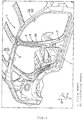
Fig. 1] Fig. 1 is a perspective view illustrating a vehicle side body structure according to an embodiment of the present invention to which a door has been mounted. - [
Fig. 2] Fig. 2 is a perspective view illustrating the vehicle side body structure. - [
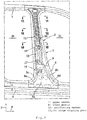
Fig. 3] Fig. 3 is a side view illustrating a center pillar and a peripheral structure thereof. - [
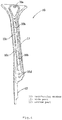
Fig. 4] Fig. 4 is a side view illustrating a reinforcing member to be mounted to the center pillar. - [
Fig. 5] Fig. 5 is a side view illustrating the main parts of an impact bar mounted to the door and the center pillar. - [
Fig. 6] Fig. 6 is a cross-sectional view taken along line VI-VI inFig. 3 . - [
Fig. 7] Fig. 7 is a cross-sectional view taken along line VII-VII inFig. 3 . - [
Fig. 8] Fig. 8 is a cross-sectional view taken along line VIII-VIII inFig. 3 . - [
Fig. 9] Fig. 9 is a cross-sectional view illustrating the main part including a cross-sectional view taken along line IX-IX inFig. 5 . - [
Fig. 10] Fig. 10 is a cross-sectional view illustrating the center pillar in the position of an upper door hinge. - [
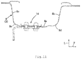
Fig. 11] Fig. 11 is a cross-sectional view illustrating the center pillar in the position of a lower door hinge. - [
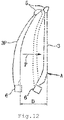
Fig. 12] Fig. 12 is an explanatory diagram used to describe a deformation mode of the door. - [
Fig. 13] Fig. 13 is an explanatory diagram used to describe a deformation mode of the door according to a comparative example. - An embodiment of a vehicle side body structure according to the present invention will be described below with reference to the drawings.
-
Figs. 1 to 3 illustrate a vehicleside body structure 1 of a 4-door sedan car, this vehicleside body structure 1 has aside part opening 2, thisside part opening 2 is partitioned into afront side opening 2a and a rear side opening 2b by apillar member 3 of a center pillar (not illustrated), and the front side opening 2a and the rear side opening 2b are closed byside doors 4 in an openable and closable manner. However, the side door for closing thefront side opening 2a is not illustrated inFig. 1 . It should be noted here that arrows F, L, and U indicate the front side, the left side, and the upper side. - In the following description, the vehicle
side body structure 1 on the right side of an automobile is assumed as an example. - The vehicle
side body structure 1 has aroof side rail 5 and aside sill 6 that extend in the front-rear direction and these members form the upper side part and the lower side part of theside part opening 2. The middle parts in the front-rear direction of theroof side rail 5 and theside sill 6 are coupled to each other by thepillar member 3 extending in the up-down direction. - It should be noted here that the center pillar includes the
pillar member 3 illustrated inFigs. 1 and2 , an inner panel (not illustrated) jointed to the inner surface inside in the vehicle width direction of thispillar member 3, and an outer panel (not illustrated) that covers the outer surface side of thepillar member 3. The center pillar is particularly formed to have a larger front-rear width in the front-rear direction toward the lower portion. The upper end portion of thepillar member 3 is joined to theroof side rail 5 and the lower end portion of thepillar member 3 is joined to theside sill 6. - The
pillar member 3 includes anupper member 7, alower member 8 joined to theupper member 7 and having a rigidity lower than a rigidity of theupper member 7, and the lower end of theupper member 7 and the upper end of thelower member 8 are welded to each other in ajoint line 9. The vertical length of theupper member 7 is particularly longer than the vertical length of thelower member 8 and is, for example, approximately 3/4 of the whole length of thepillar member 3 and the vertical length of thelower member 8 is approximately 1/4 of the while length of thepillar member 3. However, the ratios described are not limited to 3/4 and 1/4. - The
upper member 7 and thelower member 8 are particularly formed by thin plate members made of high-tensile steel, theupper member 7 is particularly formed by a plate member thicker than in thelower member 8, and theupper member 7 has a rigidity higher than a rigidity of thelower member 8. - Particularly, as illustrated in
Figs. 6 to 8 and10 , theupper member 7 has aside wall part 7a oriented in the vehicle front-rear direction, a pair of front and rearvertical wall parts side wall part 7a, and the joint parts between theside wall part 7a and the pair ofvertical wall parts rear ridge parts Figs. 3 ,5 , and11 , thelower member 8 has aside wall part 8a oriented in the vehicle front-rear direction and a pair of front and rearvertical wall parts side wall part 8a and the joint parts between theside wall part 8a and the pair ofvertical wall parts rear ridge parts - Particularly, as illustrated in
Figs. 3 to 5 , a reinforcingmember 10 is welded to the outer surface in the vehicle width direction of theupper member 7. This reinforcingmember 10 is particularly formed by a thin plate member made of high-tensile steel with a higher tensile strength than tensile strengths of the plate members theupper member 7 and thelower member 8. When thepillar member 3 is manufactured, the material of the reinforcingmember 10 is welded to the surface of the material of theupper member 7, the upper end of the material of thelower member 8 is welded to the lower end of the material of theupper member 7, and these materials are press-molded by tailored blank technology. - The upper end portion of the reinforcing
member 10 and the upper end portion of theupper member 7 are joined to theroof side rail 5. The reinforcingmember 10 particularly has awide part 11 that straddles the pair of front andrear ridge parts upper member 7 and anarrow part 12 that extends downward from thewide part 11 and covers only one of the front and rear ridge parts (rear ridge part 7e in the embodiment) 7d and 7e. The front-rear width in the front-rear direction of thewide part 11 is particularly set larger than the front-rear width in the front-rear direction of thenarrow part 12. The vertical length of thewide part 11 is, for example, approximately 3/4 of the whole length of the reinforcingmember 10 and the vertical length of thenarrow part 12 is, for example, approximately 1/4 of the whole length of the reinforcingmember 10. - It should be noted here that a
triangular opening 10a is formed in the portion of thewide part 11 close to the upper end and threelong openings 10b are formed in series withbridge parts 10c provided therebetween in the portion extending downward from thisopening 10a. - The bending rigidity of the reinforcing
member 10 against bending to the inside in the vehicle width direction is particularly adjusted via theopenings - As illustrated in
Fig. 4 , since the bending rigidity of the reinforcingmember 10 against bending to the inside in the vehicle width direction is particularly set via the front-rear width in the vehicle front-rear direction, the lower half of the reinforcingmember 10 is shaped to have a gradually smaller bending rigidity against bending to the inside in the vehicle width direction toward the lower end of the reinforcingmember 10. - Although the front-rear width of the
side wall part 7a of theupper member 7 has effects on the bending rigidity of theupper member 7, the front-rear width of theside wall part 7a is particularly maximized in the vicinity of ahinge coupling part 13 and reduces toward the lower part from the vicinity of thehinge coupling part 13. - Particularly, as illustrated in
Figs. 3 ,10 and11 , thepillar member 3 has twohinge coupling parts side door 4 is coupled, and the portion of the reinforcingmember 10 that corresponds to the upperhinge coupling part 13 is formed by the lower end portion of thewide part 11 and thenarrow part 12 extends downward from the lower end portion of thiswide part 11. The lower end portion of thewide part 11 has twobolt holes 10d for the upperhinge coupling part 13. The lowerhinge coupling part 14 is formed in the vicinity of the upper end of thelower member 8. - As illustrated in
Figs. 5 and9 , in theside door 4 disposed adjacently to thepillar member 3, animpact bar 15 that ensures the rigidity of the portion of theside door 4 near the beltline and transmits a side collision load to thepillar member 3 is provided. In the state in which theside door 4 is closed, afront end portion 15a of theimpact bar 15 overlaps with theupper member 7 and thelower member 8 in vehicle side view. - To surely transmit the side collision load from the
impact bar 15 to theupper member 7 and thelower member 8, thefront end portion 15a of theimpact bar 15 overlaps with thevertical wall parts upper member 7 and thelower member 8 in vehicle side view. - As illustrated in
Fig. 5 , so as to distribute the side collision load applied to thepillar member 3 from theimpact bar 15 to theupper member 7 and thelower member 8, thefront end portion 15a of theimpact bar 15 has aregion 16a of theupper member 7 in which the reinforcingmember 10 is present, aregion 16b of theupper member 7 in which the reinforcingmember 10 is not present, and aregion 16c that covers thelower member 8 in vehicle side view. - As illustrated in
Figs. 3 and5 , thepillar member 3 has a harness pass-throughopening 17 through which harnesses for a power window and a speaker pass and thefront end portion 15a of theimpact bar 15 covers at least a part of the harness pass-throughopening 17 in vehicle side view to protect the harnesses. Particularly, theopening 17 is formed in the vicinity of the lower end of theupper member 7, that is, the vicinity of thejoint line 9 and thisopening 17 appropriately reduces the bending rigidity of theupper member 7. - Next, the operation and the effect of the vehicle
side body structure 1 described above will be described. - Since the rigidity of the
upper member 7 is particularly set higher than the rigidity of thelower member 8 and thisupper member 7 has particularly the reinforcingmember 10 made of high-tensile steel, the rigidity of theupper member 7 and the reinforcingmember 10 is higher than that of thelower member 8. Since the lower half of the reinforcingmember 10 is shaped to have a smaller bending rigidity against bending to the inside in the vehicle width direction toward the lower end of the reinforcingmember 10, the bending rigidity of thelower member 8 is set smaller than the bending rigidity of theupper member 7 and the reinforcingmember 10 while ensuring the continuity of the bending rigidity across the whole length of theupper member 7. Since the bending rigidity of theupper member 7 can be adjusted via the reinforcingmember 10, weight reduction in thepillar member 3 can be achieved. - Accordingly, since the
upper member 7 undergoes bending deformation and thelower member 8 is mainly crashed when a side collision load is applied, the angle of bending deformation of thelower member 8 toward the vehicle interior is larger than the angle of bending deformation of theupper member 7 and a portion near the border between theupper member 7 and thelower member 8 makes intrusion into the vehicle interior at a maximum. - Since the border portion between the
upper member 7 and thelower member 8 comes close to the lower part by setting the length of theupper member 7 longer than the length of thelower member 8, the maximum amount of intrusion of thepillar member 3 into the vehicle interior at the time of a side collision can be reduced. As described above, since the roles of theupper member 7 and thelower member 8 at the time of a side collision are divided and the difference between the strengths thereof do not become so large, the behavior of thepillar member 3 at the time of a side collision becomes stable. - Specifically, as illustrated in
Fig. 12 , when a side collision load is applied to acenter pillar 3P from the outside in the vehicle width direction as indicated by an arrow P, theroof side rail 5 and theside sill 6 move to the inside in the vehicle width direction and thepillar member 3 is deformed to the state indicated by the dot-dash line through the state indicated by the dotted line. - The deformation mode of the
pillar member 3 at this time enters the state in which calmly bending occurs in a border part A between theupper member 7 and thelower member 8, theupper member 7 undergoes bending deformation toward the vehicle interior and thelower member 8 is deformed toward the vehicle interior mainly in a crashed manner, and the angle of the bending deformation of thelower member 8 is larger than the angle of the bending deformation of theupper member 7. Accordingly, an amount D of intrusion of thepillar member 3 into the vehicle interior in the border part A is maximized. -
Fig. 13 illustrates the deformation mode according to a comparative example in which a middle part of a pillar member 3' of acenter pillar 3P' is sharply bent. An amount D' of intrusion of the pillar member 3' into the vehicle interior in this case is significantly larger than the amount D of intrusion inFig. 12 . - Since the bending rigidity of the reinforcing
member 10 against bending to the inside in the vehicle width direction is particularly set via the front-rear width in the vehicle front-rear direction, the bending rigidity can be set freely by adjusting the front-rear width of the reinforcingmember 10. - Since the reinforcing
member 10 has thewide part 11 that straddles the pair of front andrear ridge parts narrow part 12 that extends downward from thiswide part 11 and covers only one (rear ridge part 7e in the embodiment) of the front andrear ridge parts upper member 7 can be reinforced by using the reinforcingmember 10 at minimum while ensuring the integrity of the reinforcingmember 10. - Since the portion of the reinforcing
member 10 corresponding to the upperhinge coupling part 13 is formed by the lower end portion of thewide part 11 and thenarrow part 12 extends downward from the lower end portion of thiswide part 11, the above effects can be obtained while suppressing intrusion of thepillar member 3 near the beltline corresponding to the upperhinge coupling part 13 into the vehicle interior at the time of a side collision. - Since the
front end portion 15a of theimpact bar 15 provided in theside door 4 overlaps with both theupper member 7 and thelower member 8 in vehicle side view when theside door 4 is closed, the collision load applied to theimpact bar 15 at the time of a side collision acts on both theupper member 7 and thelower member 8 without concentrating on one of theupper member 7 and thelower member 8, thereby stabilizing the behavior of thepillar member 3 at the time of a side collision and deforming thepillar member 3 in a desired deformation mode. - Since the
front end portion 15a of theimpact bar 15 covers theregion 16a of theupper member 7 in which the reinforcingmember 10 is present, theregion 16b of theupper member 7 in which the reinforcingmember 10 is not present, and thelower member 8 in vehicle side view, and thefront end portion 15a of theimpact bar 15 overlaps with a structural discontinuous part including the border part through which a shift from theregion 16a in which the reinforcingmember 10 is present to theregion 16b in which the reinforcingmember 10 is not present is made and the border part in which theupper member 7 is joined to thelower member 8, thepillar member 3 can be deformed in a desired deformation mode by distributing the load from theimpact bar 15 to theupper member 7 and thelower member 8 at the time of a side collision. - Since the
pillar member 3 has the harness pass-throughopening 17 and thefront end portion 15a of theimpact bar 15 covers at least a part of the harness pass-throughopening 17 in vehicle side view, the harnesses that pass through theopening 17 can be protected by thefront end portion 15a of theimpact bar 15. - Since the
front end portion 15a of theimpact bar 15 overlaps with thevertical wall parts upper member 7 and thelower member 8 in vehicle side view, the load at the time of a side collision can be surely transmitted to theupper member 7 and thelower member 8 by transmitting the load from thefront end portion 15a of theimpact bar 15 to thevertical wall parts upper member 7 and thelower member 8 at the time of a side collision. - Next, examples in which the embodiment is partially modified will be described.
- 1) Although the upper member, the lower member, and the reinforcing member of the pillar member have been particularly formed by members made of high-tensile steel, the lower member may be formed by a member made of normal steel. The material of the pillar member is not limited to the material in the embodiment described above.
- 2) Although the reinforcing member has been formed by a single member, the reinforcing member may be formed by a plurality of members.
- 3) Other than the above, those skilled in the art may make an addition to the embodiment described above as appropriate.
-
- 1: vehicle side body structure
- 2: side part opening
- 3: pillar member
- 4: side door
- 7: upper member
- 7a: side wall part
- 7b, 7c: vertical wall part
- 7d, 7e: ridge part
- 8: lower member
- 8a: side wall part
- 8b, 8c: vertical wall part
- 8d, 8e: ridge part
- 10: reinforcing member
- 11: wide part
- 12: narrow part
- 13, 14: hinge coupling part
- 15: impact bar
- 15a: front end portion
- 16a: region in which reinforcing member is present
- 16b: region in which reinforcing member is not present
Claims (13)
- A vehicle side body structure (1) comprising:a pillar member (3) including an upper member (7); a lower member that is joined to the upper member (7) and has a rigidity lower than the upper member (7); and a reinforcing member (10) provided in the upper member (7),wherein the pillar member (3) is configured to partition a side part opening (2) of a vehicle body into a front part and a rear part, andwherein a lower half of the reinforcing member (10) is shaped to have a smaller bending rigidity against bending to an inside in a vehicle width direction toward a lower end of the reinforcing member (10).
- The vehicle side body structure (1) according to claim 1,
wherein the reinforcing member (10) is set to have the bending rigidity against the bending to the inside in the vehicle width direction via a front-rear width in a vehicle front-rear direction. - The vehicle side body structure (1) according to claim 1 or 2,
wherein the upper member (7) has a pair of front and rear ridge parts (7d, 7e) configured to extend in a vehicle up-down direction. - The vehicle side body structure (1) according to claim 3,
wherein the reinforcing member (10) has a wide part (11) provided across the pair of front and rear ridge parts (7d, 7e) and a narrow part (12) that configured to extend downward from the wide part (11) and cover one of the pair of front and rear ridge parts (7d, 7e). - The vehicle side body structure (1) according to claim 3 or 4,
wherein the pillar member (3) has one or a plurality of hinge coupling parts (13, 14) configured to couple a hinge which is configured to support a door,
wherein a portion of the reinforcing member (10) corresponding to an uppermost one of the hinge coupling parts (13) is formed by a lower end portion of the wide part (11), and
wherein the narrow part (12) is configured to extend downward from the lower end portion of the wide part (11). - The vehicle side body structure (1) according to any one of the preceding claims,
wherein a vertical length of the upper member (7) is longer than a vertical length of the lower member (8). - The vehicle side body structure (1) according to any one of the preceding claims,
wherein the upper member (7) and the lower member (8) are formed by plate members made of high-tensile steel. - The vehicle side body structure (1) according to claim 7,
wherein the upper member (7) is thicker than the lower member (8). - The vehicle side body structure (1) according to any one of the preceding claims,
wherein the reinforcing member (10) is formed by a plate member made of high-tensile steel having a tensile strength, and
wherein the tensile strength of the reinforcing member (19) is higher than tensile strengths of the plate members of the upper member (7) and the lower member (8). - The vehicle side body structure (1) according to claim 4 or 5,
wherein a front-rear width in the front-rear direction of the wide part (11) is set to be larger than a front-rear width in the front-rear direction of the narrow part (12). - The vehicle side body structure (1) according to any one of the preceding claims,
wherein the lower member (8) is formed by a plate member made of normal steel. - A vehicle body structure comprising the vehicle side body structure (1) according to any one of the preceding claims.
- A vehicle comprising:a side part opening (2); andthe vehicle side body structure (1) according to any one of claims 1 to 11 or claim 12.
Applications Claiming Priority (1)
| Application Number | Priority Date | Filing Date | Title |
|---|---|---|---|
| JP2019110882A JP2020203508A (en) | 2019-06-14 | 2019-06-14 | Vehicle body side part structure |
Publications (1)
| Publication Number | Publication Date |
|---|---|
| EP3750785A1 true EP3750785A1 (en) | 2020-12-16 |
Family
ID=69844477
Family Applications (1)
| Application Number | Title | Priority Date | Filing Date |
|---|---|---|---|
| EP20162988.8A Withdrawn EP3750785A1 (en) | 2019-06-14 | 2020-03-13 | Vehicle side body structure, vehicle body structure, and vehicle |
Country Status (4)
| Country | Link |
|---|---|
| US (1) | US11148727B2 (en) |
| EP (1) | EP3750785A1 (en) |
| JP (1) | JP2020203508A (en) |
| CN (1) | CN112078664A (en) |
Families Citing this family (3)
| Publication number | Priority date | Publication date | Assignee | Title |
|---|---|---|---|---|
| JP7346377B2 (en) * | 2020-12-25 | 2023-09-19 | 豊田鉄工株式会社 | Center pillar components for vehicles and their manufacturing method |
| CN116605299A (en) * | 2023-05-31 | 2023-08-18 | 深蓝汽车科技有限公司 | Integrated side wall inner plate double-door ring structure, forming process and vehicle |
| CN122029096A (en) * | 2023-10-18 | 2026-05-12 | 日本制铁株式会社 | Impact absorbing member and vehicle body |
Citations (5)
| Publication number | Priority date | Publication date | Assignee | Title |
|---|---|---|---|---|
| GB2303589A (en) * | 1994-08-31 | 1997-02-26 | Fuji Heavy Ind Ltd | Joint between centre pillar and roof brace in a motor vehicle body structure |
| JP2010173562A (en) | 2009-01-30 | 2010-08-12 | Mazda Motor Corp | Side body structure for vehicle |
| WO2011151962A1 (en) * | 2010-06-03 | 2011-12-08 | ユニプレス株式会社 | Automobile body pillar structure |
| JP2017177915A (en) * | 2016-03-29 | 2017-10-05 | 本田技研工業株式会社 | Body structure |
| US20190168812A1 (en) * | 2017-12-04 | 2019-06-06 | Mazda Motor Corporation | Side vehicle body structure for vehicle and method for manufacturing vehicle pillar member |
Family Cites Families (7)
| Publication number | Priority date | Publication date | Assignee | Title |
|---|---|---|---|---|
| JP2001163257A (en) * | 1999-03-29 | 2001-06-19 | Nissan Motor Co Ltd | Body structure |
| DE102006027546A1 (en) * | 2006-06-14 | 2007-12-20 | Volkswagen Ag | Impact protection reinforcing part |
| DE102009043265A1 (en) * | 2009-09-29 | 2011-03-31 | Daimler Ag | Reinforcement arrangement for a door pillar of a passenger car and method for producing such a reinforcing arrangement |
| JP2015054660A (en) * | 2013-09-13 | 2015-03-23 | スズキ株式会社 | Vehicle door structure |
| JP2015147456A (en) * | 2014-02-05 | 2015-08-20 | スズキ株式会社 | Car body rear opening structure |
| JP6172079B2 (en) * | 2014-07-24 | 2017-08-02 | マツダ株式会社 | Car side body structure |
| US9969434B2 (en) * | 2016-09-01 | 2018-05-15 | Ford Global Technologies, Llc | Vehicle body B-pillar assembly with cell member |
-
2019
- 2019-06-14 JP JP2019110882A patent/JP2020203508A/en not_active Abandoned
-
2020
- 2020-03-05 CN CN202010147878.3A patent/CN112078664A/en active Pending
- 2020-03-13 US US16/817,913 patent/US11148727B2/en active Active
- 2020-03-13 EP EP20162988.8A patent/EP3750785A1/en not_active Withdrawn
Patent Citations (5)
| Publication number | Priority date | Publication date | Assignee | Title |
|---|---|---|---|---|
| GB2303589A (en) * | 1994-08-31 | 1997-02-26 | Fuji Heavy Ind Ltd | Joint between centre pillar and roof brace in a motor vehicle body structure |
| JP2010173562A (en) | 2009-01-30 | 2010-08-12 | Mazda Motor Corp | Side body structure for vehicle |
| WO2011151962A1 (en) * | 2010-06-03 | 2011-12-08 | ユニプレス株式会社 | Automobile body pillar structure |
| JP2017177915A (en) * | 2016-03-29 | 2017-10-05 | 本田技研工業株式会社 | Body structure |
| US20190168812A1 (en) * | 2017-12-04 | 2019-06-06 | Mazda Motor Corporation | Side vehicle body structure for vehicle and method for manufacturing vehicle pillar member |
Also Published As
| Publication number | Publication date |
|---|---|
| CN112078664A (en) | 2020-12-15 |
| US11148727B2 (en) | 2021-10-19 |
| US20200391800A1 (en) | 2020-12-17 |
| JP2020203508A (en) | 2020-12-24 |
Similar Documents
| Publication | Publication Date | Title |
|---|---|---|
| EP2030872B1 (en) | Lower structure of vehicle body | |
| JP5407372B2 (en) | Vehicle side body structure | |
| US6575525B2 (en) | Reinforced door frame for a motor vehicle | |
| JP5407367B2 (en) | Vehicle side body structure | |
| EP3712044B1 (en) | Vehicle body structure of vehicle | |
| JP2011088596A (en) | Vehicle body constitution member for vehicle | |
| EP3498575B1 (en) | Side vehicle body structure for vehicle and method for manufacturing vehicle pillar member | |
| EP3770044B1 (en) | Vehicle-body structure of vehicle, and vehicle | |
| EP3770048A1 (en) | Vehicle-body structure of vehicle, and vehicle | |
| US11148727B2 (en) | Vehicle side body structure | |
| JP2002347655A (en) | Pillar reinforcing structure for automobile | |
| EP2371678A1 (en) | Automotive vehicle body side structure | |
| EP3750726B1 (en) | Vehicle side body structure, vehicle body structure, and vehicle | |
| JP2012056407A (en) | Reinforcing structure in vehicle body framework for vehicle | |
| EP3950467B1 (en) | Composite elongated member | |
| JP7800268B2 (en) | Vehicle side body structure | |
| CN112046614B (en) | Upper vehicle body structure | |
| JPS61282172A (en) | Rear body structure in automobile | |
| JP2000177631A (en) | Car side body structure | |
| JP2023141370A (en) | Door beam catcher structure | |
| JP3997187B2 (en) | Automobile beltline structure | |
| JPH10316020A (en) | Car side body structure | |
| CN221162141U (en) | Vehicle door assembly and vehicle with same | |
| JPS6397473A (en) | Side sill reinforcement construction for automobile | |
| JP7363652B2 (en) | Vehicle front structure |
Legal Events
| Date | Code | Title | Description |
|---|---|---|---|
| PUAI | Public reference made under article 153(3) epc to a published international application that has entered the european phase |
Free format text: ORIGINAL CODE: 0009012 |
|
| STAA | Information on the status of an ep patent application or granted ep patent |
Free format text: STATUS: THE APPLICATION HAS BEEN PUBLISHED |
|
| AK | Designated contracting states |
Kind code of ref document: A1 Designated state(s): AL AT BE BG CH CY CZ DE DK EE ES FI FR GB GR HR HU IE IS IT LI LT LU LV MC MK MT NL NO PL PT RO RS SE SI SK SM TR |
|
| AX | Request for extension of the european patent |
Extension state: BA ME |
|
| STAA | Information on the status of an ep patent application or granted ep patent |
Free format text: STATUS: REQUEST FOR EXAMINATION WAS MADE |
|
| 17P | Request for examination filed |
Effective date: 20210615 |
|
| RBV | Designated contracting states (corrected) |
Designated state(s): AL AT BE BG CH CY CZ DE DK EE ES FI FR GB GR HR HU IE IS IT LI LT LU LV MC MK MT NL NO PL PT RO RS SE SI SK SM TR |
|
| GRAP | Despatch of communication of intention to grant a patent |
Free format text: ORIGINAL CODE: EPIDOSNIGR1 |
|
| STAA | Information on the status of an ep patent application or granted ep patent |
Free format text: STATUS: GRANT OF PATENT IS INTENDED |
|
| INTG | Intention to grant announced |
Effective date: 20220727 |
|
| STAA | Information on the status of an ep patent application or granted ep patent |
Free format text: STATUS: THE APPLICATION IS DEEMED TO BE WITHDRAWN |
|
| 18D | Application deemed to be withdrawn |
Effective date: 20221207 |